HEADLIGHTS
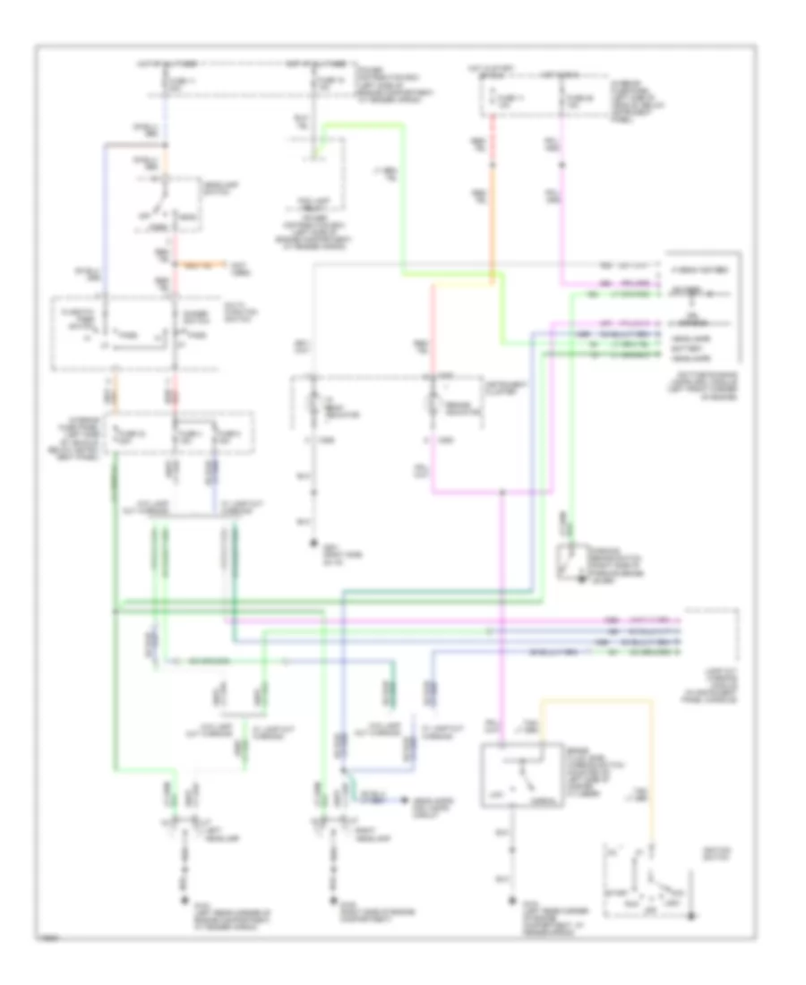
Headlamps Wiring Diagram, with Autolamps for Ford Explorer 1995
 https://portal-diagnostov.com/license.html
Automotive Electricians Portal FZCO
Automotive Electricians Portal FZCO
https://portal-diagnostov.com/license.html
https://portal-diagnostov.com/license.html
Automotive Electricians Portal FZCO
Automotive Electricians Portal FZCO
List of elements for Headlamps Wiring Diagram, with Autolamps for Ford Explorer 1995:
- "hi beam" indicator
- (not used)
- C280
- C286
- C287
- C338
- C350
- Day/night mirror/ autolamp sensor (mounted in rear view mirror)
- Day/nt mir out
- Dimmer relay
- Dimmer switch
- Exterior lights system
- Flash-to- pass switch
- Fuse 11 10a
- Fuse 11 20a
- Fuse 3 15a
- Fuse 33 20a
- Fuse 4 15a
- Fuse 7 30a
- Fuse 8 15a
- Fuse 9 10a
- G104 (left rear corner of engine compartment, at fender apron)
- G105 (right side of engine compartment)
- G200 (left kick panel)
- G201 (right side of i/p)
- Generic electronic module (gem) (behind center of i/p)
- Ground
- Head
- Headlamp relay
- Headlamp switch
- Headlamps circuit (w/ drl) (daytime running lamps module pin 6)
- Headlamps circuit (w/ drl) (daytime running lamps module pin 8)
- Headlamps/ fog lamps circuit
- Hot at all times
- Hot in start or run
- Ignition
- Instrument cluster
- Interior fuse panel (left side of vehicle, below instrument panel)
- Lamp out warning module (in instrument panel console)
- Left headlamp
- Memory seat module (below left front seat)
- Mirrors system (automatic day/night miror)
- Multi- function switch
- Off
- Park
- Park lamp relay
- Pass
- Power
- Power distribution box (left side of engine compartment, at fender apron)
- Relay module (behind center of i/p)
- Relay output
- Remote anti-theft personality (rap) module (at left rear quarter panel)
- Right headlamp
- W/ lamp out warning
- W/ memory seat
- W/o lamp out warning
- W/o memory seat
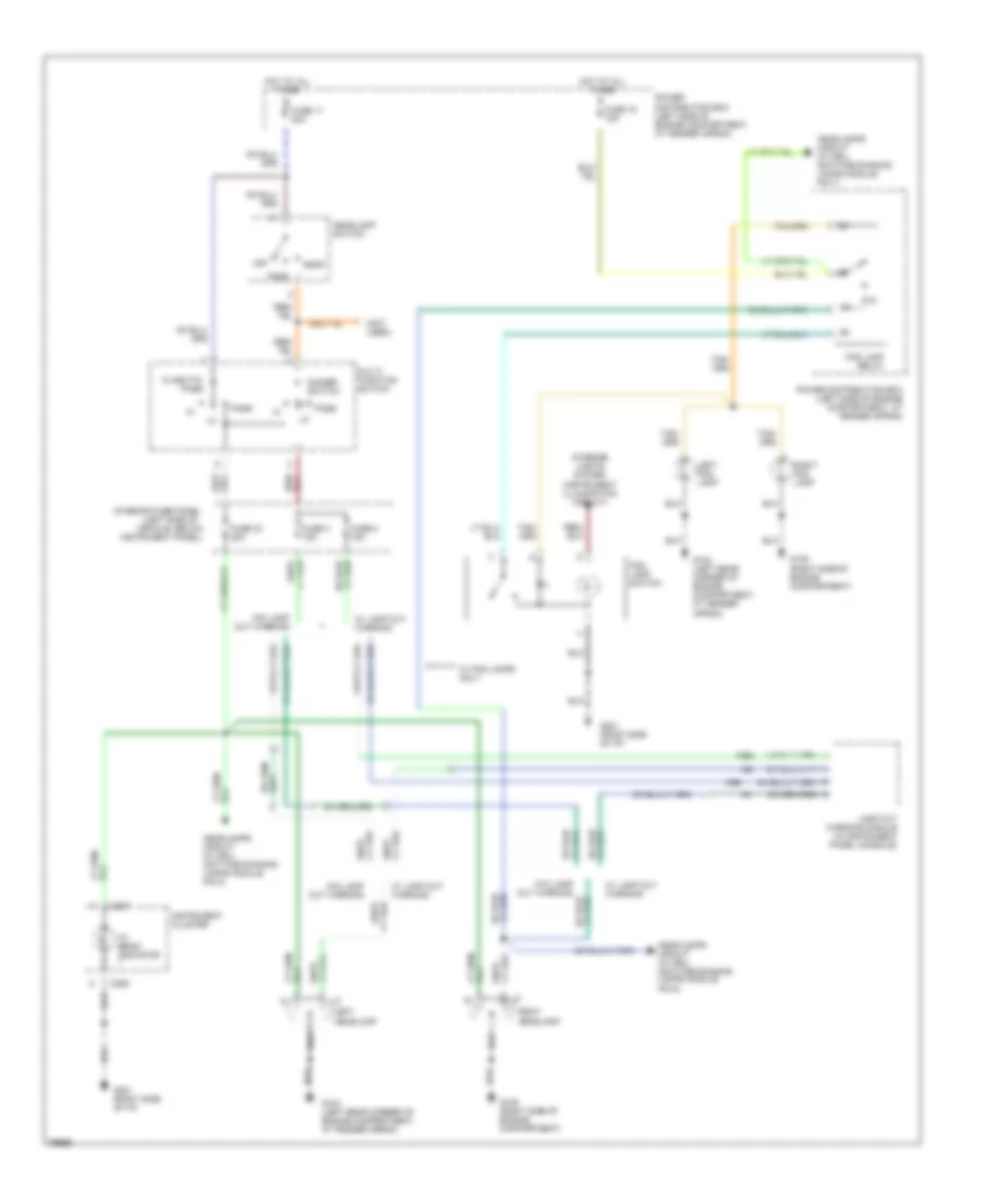
Headlamps Wiring Diagram, with DRL for Ford Explorer 1995
 https://portal-diagnostov.com/license.html
Automotive Electricians Portal FZCO
Automotive Electricians Portal FZCO
https://portal-diagnostov.com/license.html
https://portal-diagnostov.com/license.html
Automotive Electricians Portal FZCO
Automotive Electricians Portal FZCOList of elements for Headlamps Wiring Diagram, with DRL for Ford Explorer 1995:
- "brake" indicator
- "hi beam" indicator
- (not used)
- Acc
- Battery
- Brake fluid level warning switch (mounted on left side of master cylinder)
- C286
- C287
- C288
- Daytime running lamps (drl) module (left front corner of engine)
- Dimmer switch
- Drl disable
- Flash-to- pass switch
- Fog lamp relay
- Fuse 11 10a
- Fuse 11 20a
- Fuse 15 15a
- Fuse 26 15a
- Fuse 33 20a
- Fuse 4 15a
- Fuse 8 15a
- G104 (left rear corner of engine compartment, at fender apron)
- G105 (right side of engine compartment)
- G201 (right side of i/p)
- Head
- Headlamp switch
- Headlamps
- Headlamps/ fog lamps circuit
- Hi beam ind feed
- Hot at all times
- Hot in run
- Hot in start or run
- Ign feed
- Ignition switch
- Instrument cluster
- Interior fuse panel (left side of vehicle, below instru- ment panel)
- Interior fuse panel (left side of vehicle, below instrument panel)
- Lamp out warning module (in instrument panel console)
- Left headlamp
- Lock
- Low
- Multi- function switch
- Normal
- Off
- Park
- Parking brake switch (right side of parking brake lever)
- Pass
- Power distribution box (left side of engine compartment, at fender apron)
- Right headlamp
- Run
- Start
- W/ lamp out warning
- W/o lamp out warning
Headlamps/Fog Lamps Wiring Diagram for Ford Explorer 1995
 https://portal-diagnostov.com/license.html
Automotive Electricians Portal FZCO
Automotive Electricians Portal FZCO
https://portal-diagnostov.com/license.html
https://portal-diagnostov.com/license.html
Automotive Electricians Portal FZCO
Automotive Electricians Portal FZCOList of elements for Headlamps/Fog Lamps Wiring Diagram for Ford Explorer 1995:
- "hi beam" indicator
- (left side of
- (not used)
- 87a
- C286
- C287
- Dimmer switch
- Flash-to- pass
- Fog lamp relay
- Fog lamp switch
- Fuse 11 20a
- Fuse 15 15a
- Fuse 33 20a
- Fuse 4 15a
- Fuse 8 15a
- G104 (left rear corner of engine compartment, at fender apron)
- G105 (right side of engine compartment)
- G105 (right side of engine compartment)
- G201 (right side of i/p)
- Head
- Headlamp switch
- Headlamps circuit (w/ drl) (daytime running lamps module pin 6)
- Headlamps circuit (w/ drl) (daytime running lamps module pin 7)
- Headlamps circuit (w/ drl) (daytime running lamps module pin 8)
- Hot at all times
- Instrument cluster
- Instrument panel)
- Interior fuse panel
- Interior lights system (instrument illumination circuit)
- Lamp out warning module (in instrument panel console)
- Left fog lamp
- Left headlamp
- Multi- function switch
- Off
- Park
- Pass
- Power distribution box (left side of engine compartment, at fender apron)
- Power distribution box (left side of engine compartment. at fender apron)
- Right fog lamp
- Right headlamp
- Vehicle, below
- W/ fog lamps only
- W/ lamp out warning
- W/o lamp out warning

 Čeština
 Dansk
Dansk Deutsch
 Ελληνικά
 English
 English
 Español
 Suomi
Suomi Français
 Français
 עברית
עברית Hrvatski
 Magyar
 Italiano
 日本語
日本語 한국어
한국어 Nederlands
 Polski
 Português
 Português
 Română
 Русский
 Slovenčina
 Slovenščina
 Svenska
 中文 (中国)
