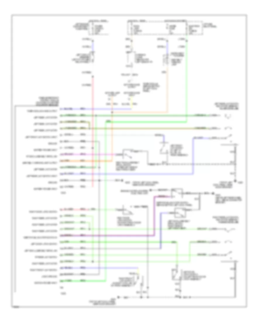
PASSIVE RESTRAINTS
Passive Restraint Wiring Diagram for Mercury Villager GS 1995
 https://portal-diagnostov.com/license.html
Automotive Electricians Portal FZCO
Automotive Electricians Portal FZCO
https://portal-diagnostov.com/license.html
https://portal-diagnostov.com/license.html
Automotive Electricians Portal FZCO
Automotive Electricians Portal FZCO
List of elements for Passive Restraint Wiring Diagram for Mercury Villager GS 1995:
- (top of left cowl panel, near door grommet)
- Activate chime input
- Activate chime output
- Activate lamp output
- Battery power input
- C223
- C225
- Electron ign fuse 26 10a
- Engine controls system (fuel tank unit)
- G200
- G200 (top of left cowl panel, near door grommet)
- G402 (above left rear wheel well, above connector bracket)
- Ground
- Hot at all times
- Hot in run or start
- I/p fuse/ relay panel
- Ignition power input
- Inertia fuel shut-off switch (behind bottom left cowl panel)
- Inertia fuel shutoff switch in
- Instrument cluster
- Left circuit breaker (left of i/p fuse/ relay panel)
- Left door latch switch
- Left door latch switch (on left front door latch assembly)
- Left engine compartment fuse panel
- Left front limit switch (in left "a" pillar, on track assembly)
- Left front limit switch input
- Left rear limit motor
- Left rear limit switch and motor assembly (in left "b" pillar)
- Left rear limit switch input
- Left shoulder belt spool sw
- Left shoulder belt spool switch (right side of left front seat)
- Logic ground
- Meter fuse 10a
- Nca
- Ni03
- Passive restraint control module (mounted on center i/p support bracket)
- Power window fuse 30a
- Pp01
- Pp02
- Pp03
- Pp04
- Pp05
- Pp07
- Pp08
- Pp09
- Pp10
- Pp11
- Pp12
- Pp13
- Pp14
- Pp15
- Pp17
- Pp18
- Pp20
- Pp21
- Pp22
- Pp23
- Pp25
- Ppe1
- Ppe2
- Ppe3
- Right door latch switch
- Right door latch switch (on right front door latch assembly)
- Right front limit switch
- Right front limit switch (in right "a" pillar, on track assembly)
- Right rear limit motor
- Right rear limit switch and motor assembly (in right "b" pillar)
- Right shoulder belt spool switch (lower left side of right front seat)
- Room lamp fuse 25 15a
- Rt rear limit switch
- Rt shoulder belt spool sw
- Seat belt warning lamp
- Seat belt warning lamp output
- Timer module (behind bottom of left cowl panel)
- Timer module chime output
- Warning chime (behind top left side of i/p)
 Čeština
 Dansk
Dansk Deutsch
 Ελληνικά
 English
 English
 Español
 Suomi
Suomi Français
 Français
 עברית
עברית Hrvatski
 Magyar
 Italiano
 日本語
日本語 한국어
한국어 Nederlands
 Polski
 Português
 Português
 Română
 Русский
 Slovenčina
 Slovenščina
 Svenska
 中文 (中国)
 Türkçe
