POWER DISTRIBUTION
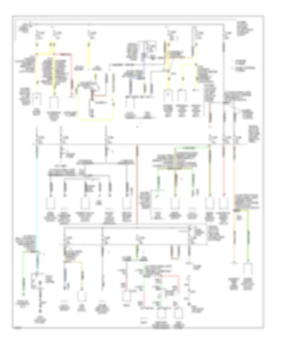
Power Distribution Wiring Diagram (1 of 5) for Ford Econoline E250 2003
 https://portal-diagnostov.com/license.html
Automotive Electricians Portal FZCO
Automotive Electricians Portal FZCO
https://portal-diagnostov.com/license.html
https://portal-diagnostov.com/license.html
Automotive Electricians Portal FZCO
Automotive Electricians Portal FZCO
List of elements for Power Distribution Wiring Diagram (1 of 5) for Ford Econoline E250 2003:
- module (gpcm)
- (e550 : in engine control sensor harness, near breakout to battery junction box) (5.4l ngv: in engine control sensor harness, near breakout to c219) s183
- (ends in harness)
- (except stripped
- (except stripped chassis) s225 s280
- (in breakout to battery junction box) s101
- (in engine control sensor harness, in breakout to abs control module)
- (in engine control sensor harness, in breakout to battery junction box) s116
- (in engine control sensor harness, near breakout to c219) s115
- (in fuel charge wiring harness, near breakout to glow plug control module) s192
- (in fuel charge wiring harness, near breakout to manifold intake air heater relay)
- (in starter relay to fuse junction panel harness, in breakout to starter relay)
- (in window regulator relay switch harness, near breakout to c248) s254
- (in window regulator relay switch harness, w/o rse: near breakout to central jb) w/ rse: near breakout to c237)
- 5.4l ngv
- A/c clutch relay
- Abs control module
- Battery
- Battery 2 (diesel)
- Battery junction box (bjb) (in left front of engine compt)
- Blower motor relay
- Breakout to c237) (stripped chassis: in breakout to ignition switch)
- C1273a
- C1273b
- C3140b
- California
- Central junction box (cjb) (left side of dash, near kick panel)
- Chassis: near
- Clearance lamp relay (e550)
- Console 1 power point (w/ rear seat entertainment system)
- Console 2 power point (w/ rear seat entertainment system)
- Cutaway
- Daytime running lamps (drl) module
- E550
- Except california
- Except cutaway
- Except stripped chassis
- From a fuse 15 (diagram 1 of 5)
- Fuel pump relay
- Fuse
- Fuse 10a
- Fuse 15a
- Fuse 20a
- Fuse 20a (e550)
- Fuse 30a
- Fuse 30a (diesel)
- Fuse 40a
- Fuse 50a
- Fuse 60a
- Fused battery feed
- Generator
- Glow plug control
- Glow plug relay
- Horn relay
- Injector driver module (idm) power relay
- Main light switch
- Manifold intake air heater relay
- Modified vehicle power
- Natural gas vehicle (ngv) module
- Nca
- Power point (except cutaway)
- Rear a/c blower speed relay 1
- Red
- Remote keyless entry
- Remote keyless entry module
- S1008
- S1010 (in alternator rectifier system wiring harness, in breakout to battery junction box)
- S1011 (in alternator rectifier system wiring harness, in breakout to battery junction box)
- S1012 (7.3l di turbo disel) (in alternator to starter motor solenoid harness, near breakout to starter relay)
- S1020
- S178 (7.3l di turbo disel) (in alternator rectifier system wiring harness, in breakout to c1282)
- S187 (in fuel charge wiring harness, near breaqkout to starter relay)
- S191
- S233
- S235
- S257 (in window regulator relay switch harness, near breakout to c311)
- S266
- Secondary generator (diesel)
- Starter motor
- Starter relay
- Stripped chassis
- To fuse 17 (diagram 1 of 5)
- To fuse 9 (diagram 2 of 5)
- To ignition switch (diagram 3 of 5)
- Trailer electronic brake control connector
- W/ rse
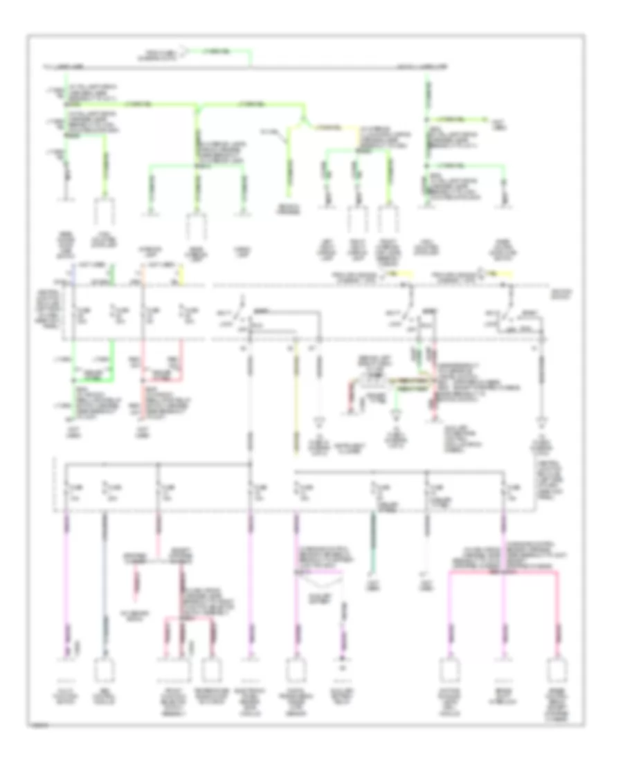
Power Distribution Wiring Diagram (2 of 5) for Ford Econoline E250 2003
 https://portal-diagnostov.com/license.html
Automotive Electricians Portal FZCO
Automotive Electricians Portal FZCO
https://portal-diagnostov.com/license.html
https://portal-diagnostov.com/license.html
Automotive Electricians Portal FZCO
Automotive Electricians Portal FZCOList of elements for Power Distribution Wiring Diagram (2 of 5) for Ford Econoline E250 2003:
- (in breakout to battery junction box)
- (in engine control sensor harness, near breakout to c237) (except stripped chassis, cutaway) s129
- (in left front door window regulator harness, near breakout to master window/door lock/unlock switch) s506
- (in main wiring harness, in breakout to c219) s218
- (in main wiring harness, near breakout to c219) (stripped chassis, cutaway) s2020
- (in main wiring harness, under left side of dash) s276
- (in window regulator relay switch harness, near breakout to c248)
- (in window regulator relay switch harness, near breakout to ignition switch) s227
- (in window regulator relay switch harness, near breakout to ignition switch) s230
- (not used)
- (stripped chassis: in engine
- 1.2 mh
- Aux battery
- Auxiliary battery relay
- Batt
- Battery 2
- Battery charge trailer tow relay
- Battery junction box (bjb) (in left front of engine compt)
- Brake pedal position switch
- Brake pressure switch
- Breakout to battery junction box)
- C202a
- C202b
- C2188a
- C220a
- C3077a
- C3140a
- Central junction box (cjb) (left side of dash, near kick panel)
- Control
- Data link connector (dlc)
- Dealer- fitted
- Driver side front seat adjust switch
- Electronic crash sensor (ecs) module
- Except stripped chassis
- Except stripped chassis, cutaway
- Exterior rear view mirror switch
- From b fuse 12 (diagram 1 of 5)
- Front cigar lighter
- Front passenger window/ door lock switch
- Fuse 10a
- Fuse 15a
- Fuse 20a
- Fuse 25a
- Fuse 30a
- Fuse 40a 60a
- Fuse 5a
- Fuse 60a
- G203 (left side of dash)
- Hinged side door
- Instrument cluster
- Main light switch
- Master window/ door lock/ unlock switch
- Memory lock module (sliding side door)
- Multi- function switch
- Nca
- Near kick panel)
- Off
- Parking lamp trailer tow relay
- Pcm power relay
- Power choke 1
- Power point
- Powertrain control module (pcm)
- Radio
- Rear doors door lock switch
- Rear seat entertainment (rse) module
- Red
- Remote keyless entry module
- Reversing lamp trailer tow relay
- Rke only
- Rse system
- S108
- S109 (in engine control sensor harness, in breakout to battery junction box)
- S110 (in engine control sensor harness, in breakout to battery junction box)
- S148
- S175 (except stripped chassis : in engine control sensor harness, in sensor harness, near breakout to c219)
- S207
- S237
- Stop lamp relay
- Stripped chassis
- To fuse 4 (diagram 5 of 5)
- Video cassette player
- W/ remote keyless entry
- W/o aux battery
- W/o remote keyless entry
- W/o rse system
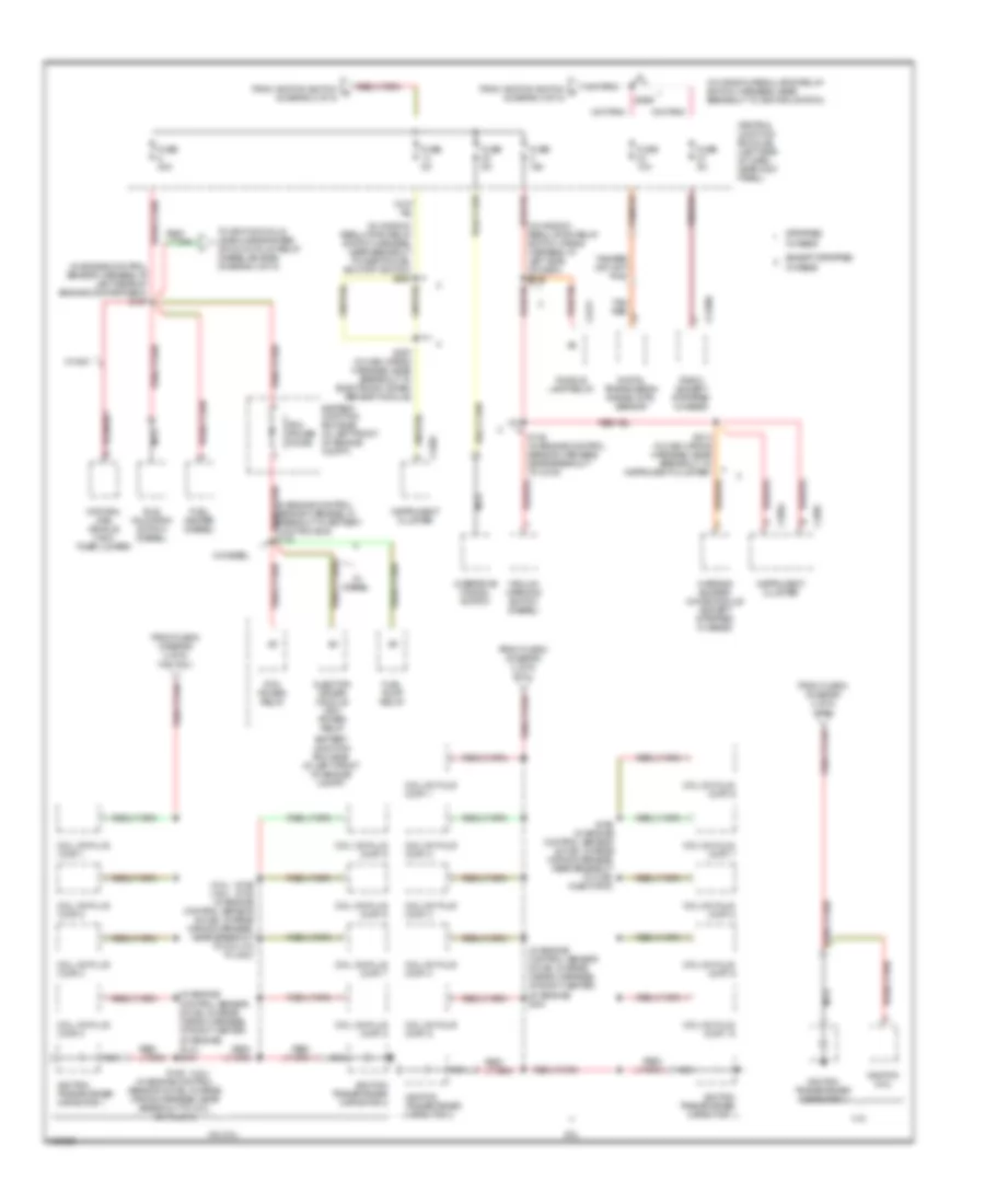
Power Distribution Wiring Diagram (3 of 5) for Ford Econoline E250 2003
 https://portal-diagnostov.com/license.html
Automotive Electricians Portal FZCO
Automotive Electricians Portal FZCO
https://portal-diagnostov.com/license.html
https://portal-diagnostov.com/license.html
Automotive Electricians Portal FZCO
Automotive Electricians Portal FZCOList of elements for Power Distribution Wiring Diagram (3 of 5) for Ford Econoline E250 2003:
- (behind left side of dash) in-line fuse
- (dealer- fitted)
- (ends in harness)
- (in engine control sensor harness, in breakout to battery junction box) s113
- (in engine control sensor harness, near breakout to c237) (except stripped chassis) s131
- (in interior illumination wiring harness, near breakout to c934) s900
- (in interior lamps wiring harness, near breakout to interior lamp) s912
- (in main wiring harness, near breakout to c219) (stripped chassis) s282
- (near breakout to overdrive cancel switch) s281 s229 (near breakout to ignition switch)
- (not used)
- (stripped chassis) (except stripped chassis)
- A/c demand signal
- Abs control module
- Acc
- Auxiliary battery
- Auxiliary battery relay
- Auxiliary powertrain control module (apcm) (diesel)
- Brake shift interlock
- Breakout to front function selector switch assembly) s203
- C202a
- C220a
- C294a
- Cargo lamp
- Central junction box (cjb) (left side of dash, near kick panel)
- Daytime running lamps (drl) module
- Dealer fitted
- Dealer- fitted
- Digital transmission range (dtr) sensor
- Electronic crash sensor (ecs) module
- Except stripped chassis
- From fuse 4 j (diagram 5 of 5)
- From splice s225 c (diagram 1 of 5)
- From splice s225 d (diagram 1 of 5)
- Front function selector switch assembly
- Front interior/ map lamps assembly (wagon)
- Full headliner
- Fuse
- Fuse 10a
- Fuse 15a
- Fuse 20a
- Fuse 30a
- Fuse 5a
- High mounted stoplamp
- Ign
- Ignition switch
- Instrument cluster
- Interior lamp
- Left vanity mirror lamp
- Lock
- Multi- function switch
- Nca
- Near breakout to c237)
- Off
- Rear doors door ajar switch
- Rear interior lamp
- Red/
- Right vanity mirror lamp
- Run
- Rv van
- S249 (in window regulator relay switch harness, red/
- S302 (in taillamp wiring harness, near breakout to c311)
- Speed control servo (except stripped chassis)
- Start
- Stripped chassis
- Temperature blend door actuator
- To c237)
- To fuse 2 (diagram 4 of 5)
- To fuse 34 (diagram 4 of 5)
- To fuse 9 (diagram 5 of 5)
- W/o full headliner
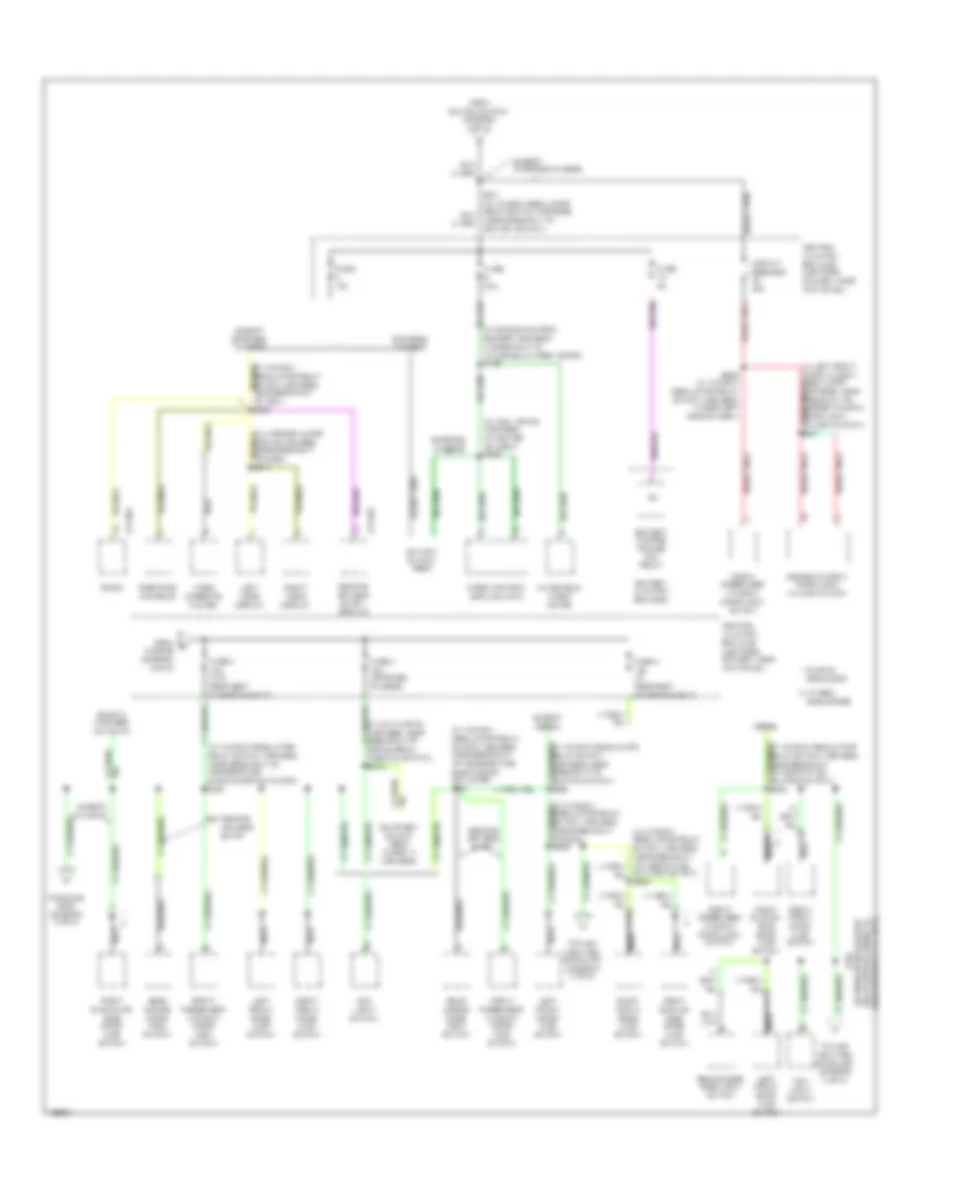
Power Distribution Wiring Diagram (4 of 5) for Ford Econoline E250 2003
 https://portal-diagnostov.com/license.html
Automotive Electricians Portal FZCO
Automotive Electricians Portal FZCO
https://portal-diagnostov.com/license.html
https://portal-diagnostov.com/license.html
Automotive Electricians Portal FZCO
Automotive Electricians Portal FZCOList of elements for Power Distribution Wiring Diagram (4 of 5) for Ford Econoline E250 2003:
- (4.6l)
- (5.4l) (4.6l)
- (in engine control sensor & fuel charge wiring harness, at right center of engine) (5.4l) s161
- (in engine control sensor & fuel charge wiring harness, at right center of engine) s161
- (in engine control sensor harness, at left rear of engine compartment) s127
- (in window regulator relay switch harness, near breakout to ignition switch)
- (in window regulator relay switch harness, near breakout to inertia fuel shutoff switch) s265
- (in window regulator relay switch wiring harness, at left side of dash) s216
- 4.2l
- 4.6l/5.4l
- 6.8l
- Battery junction box (bjb) (in left front of engine compt)
- C2188a
- C220a
- C220c
- C3217
- Central junction box (cjb) (left side of dash, near kick panel)
- Coil on plug (cop) 1
- Coil on plug (cop) 10
- Coil on plug (cop) 2
- Coil on plug (cop) 3
- Coil on plug (cop) 4
- Coil on plug (cop) 5
- Coil on plug (cop) 6
- Coil on plug (cop) 7
- Coil on plug (cop) 8
- Coil on plug (cop) 9
- Digital transmission range (dtr) sensor
- Except stripped chassis
- From fuse 8 (diagram 4 of 5) (4.2l)
- From fuse 8 (diagram 4 of 5) (4.6l/5.4l)
- From fuse 8 (diagram 4 of 5) (6.8l)
- From ignition switch f (diagram 3 of 5)
- From ignition switch g (diagram 3 of 5)
- Fuel heater (diesel)
- Fuel pump relay
- Fuse 10a
- Fuse 15a
- Fuse 30a
- Fuse 5a
- Idle validation switch (diesel)
- Ignition coil
- Ignition transformer capacitor 1
- Ignition transformer capacitor 2
- Injector driver module (idm) power relay
- Instrument cluster
- Natural gas vehicle (ngv) timer jumper
- Nca
- Overdrive cancel switch
- Pcm power diode
- Pcm power relay
- Puddle lamp relay
- Radio (except stripped chassis)
- S146 (in engine control sensor harness, near breakout to c219)
- S150 (in engine control sensor & fuel charge wiring harness, near breakout to coil on plug 3)
- S156 s193 (in engine control sensor & fuel charge wiring harness, near breakout to coil on plug 8)
- S162 (in engine control sensor & fuel charge wiring harness, near breakout to fuel injector 8)
- S213 (in main wiring harness, near breakout to instrument cluster)
- S267 (in main wiring harness, near breakout to electronic crash sensor module)
- S269
- Stripped chassis
- Tan/ red
- Tan/red
- To ignition coils (gasoline engines) or glow plug relay (diesel engine) (diagram 4 of 5)
- Vacuum warning switch (diesel)
- W/ diesel
- W/ ngv
- Warning buzzer/ chime module (except stripped chassis)
Power Distribution Wiring Diagram (5 of 5) for Ford Econoline E250 2003
 https://portal-diagnostov.com/license.html
Automotive Electricians Portal FZCO
Automotive Electricians Portal FZCO
https://portal-diagnostov.com/license.html
https://portal-diagnostov.com/license.html
Automotive Electricians Portal FZCO
Automotive Electricians Portal FZCOList of elements for Power Distribution Wiring Diagram (5 of 5) for Ford Econoline E250 2003:
- (in engine control sensor harness, in breakout to windshield wiper motor) s128
- (in main wiring harness, at center of dash) s208
- (in main wiring harness, near breakout to brake pedal position switch) s219
- (in window regulator relay switch harness, near breakout to temperature blend door actuator) s221
- (in window regulator relay switch harness, near breakout to g204)
- (in window regulator relay switch harness, near breakout to ignition switch) s294
- (in window regulator relay switch harness, near breakout to inertia fuel shutoff switch) s290
- (in window regulator relay switch harness, near breakout to temperature blend door actuator) s221
- Battery charge trailer tow relay
- Battery junction box (bjb)
- C2188a
- C3140a
- Central junction box (cjb) (left side of dash, near kick panel)
- Circuit breaker 20a
- Courtesy switch feed (taped in harness)
- Diesel
- Ends in harness (cutaway)
- Except cutaway
- Except diesel
- Except stripped chassis
- From e fuse 28 (diagram 2 of 5)
- From ignition switch (diagram 3 of 5)
- Front passenger window/ door lock switch
- Fuse 15a
- Fuse 30a
- Fuse 4 15a (stripped chassis)
- Fuse 4 15a (w/ rear seat entertainment)
- Fuse 4 15a (w/o rear seat entertainment)
- Fuse 5a
- Hinged side doors
- Ignition switch feed
- Left front door ajar switch
- Left video display
- Main light switch
- Master window/ door lock unlock switch
- Nca
- Overhead console
- Radio
- Rear doors door lock switch
- Remote keyless entry
- Remote keyless entry module
- Right front door ajar switch
- Right sliding or side door ajar switch
- Right sliding/ side door ajar switch
- Right video display
- S236 (in window regulator relay switch harness, under left side of dash)
- S296
- Shutoff switch) s290
- Sliding side door
- Stripped chassis
- To high mounted stoplamp (diagram 3 of 5)
- To splice s302 (diagram 3 of 5)
- Video cassette player
- Windshield wiper motor
- Wiper control module (wcm)

 Čeština
 Dansk
Dansk Deutsch
 Ελληνικά
 English
 English
 Español
 Suomi
Suomi Français
 Français
 עברית
עברית Hrvatski
 Magyar
 Italiano
 日本語
日本語 한국어
한국어 Nederlands
 Polski
 Português
 Português
 Română
 Русский
 Slovenčina
 Slovenščina
 Svenska
 中文 (中国)
