AIR CONDITIONING
Automatic A/C Wiring Diagram, Dual A/C Wiring Diagram (1 of 4) for Porsche Cayenne Turbo 2003
 https://portal-diagnostov.com/license.html
Automotive Electricians Portal FZCO
Automotive Electricians Portal FZCO
https://portal-diagnostov.com/license.html
https://portal-diagnostov.com/license.html
Automotive Electricians Portal FZCO
Automotive Electricians Portal FZCO
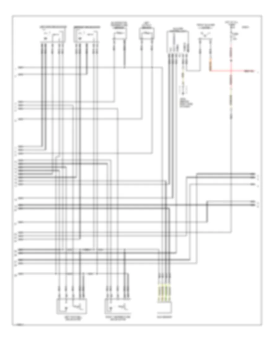
List of elements for Automatic A/C Wiring Diagram, Dual A/C Wiring Diagram (1 of 4) for Porsche Cayenne Turbo 2003:
- (pins b1 to b24 not used)
- (pins d1 to d12 not used)
- 5v ref
- A10
- A11
- A12
- A13
- A14
- A15
- A16
- A17
- A18
- A19
- A20
- A21
- A22
- A23
- A24
- Actuation blwr cntrl unit
- Air quality sensor
- Blowing out temp sensor
- C10
- C11
- C12
- C13
- C14
- C15
- C16
- C17
- C18
- C19
- C20
- C21
- C22
- C23
- C24
- Can high
- Can low
- Center outlet drive motor
- Computer data lines system
- Defrost flap
- E10
- E11
- E12
- Externally cntrld comp
- Feedback voltage
- Footwell flap
- Fresh air recirc air flap
- Fresh air/ circulating air drive motor
- Gp22 (behind right side of dash)
- Heated windscreen
- Intake temp sensor
- Left sidewall sun sensor
- Left temp flap
- Left temperature drive motor
- Left/right climatronic control unit
- Nca
- Passenger air flow
- Pressure sensor
- Rear evaporative air intake temperature sensor
- Right footwell output sensor
- Right output sensor
- Right sidewall sun sensor
- Right temp flap
- Right temp flap right temp flap
- Sensor ground
- Signal ground
- Stationary heater
- Temp sensor signal
- Term 30a
- Term 31
- Water cooling temp sen
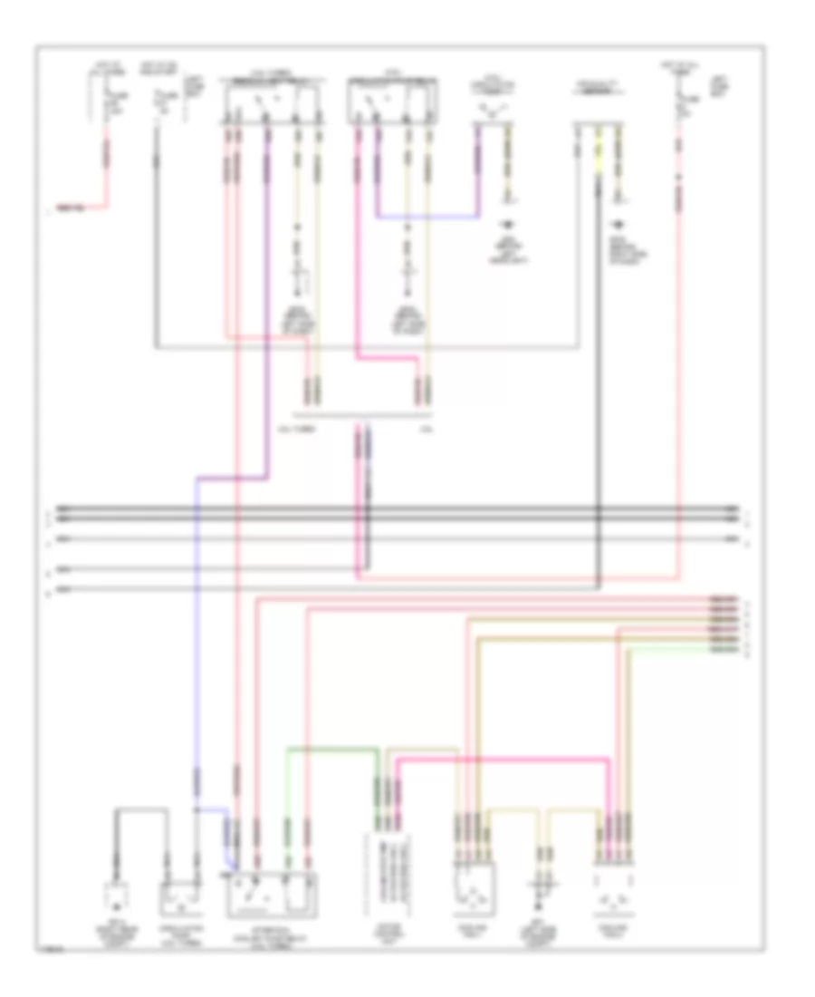
Automatic A/C Wiring Diagram, Dual A/C Wiring Diagram (2 of 4) for Porsche Cayenne Turbo 2003
 https://portal-diagnostov.com/license.html
Automotive Electricians Portal FZCO
Automotive Electricians Portal FZCO
https://portal-diagnostov.com/license.html
https://portal-diagnostov.com/license.html
Automotive Electricians Portal FZCO
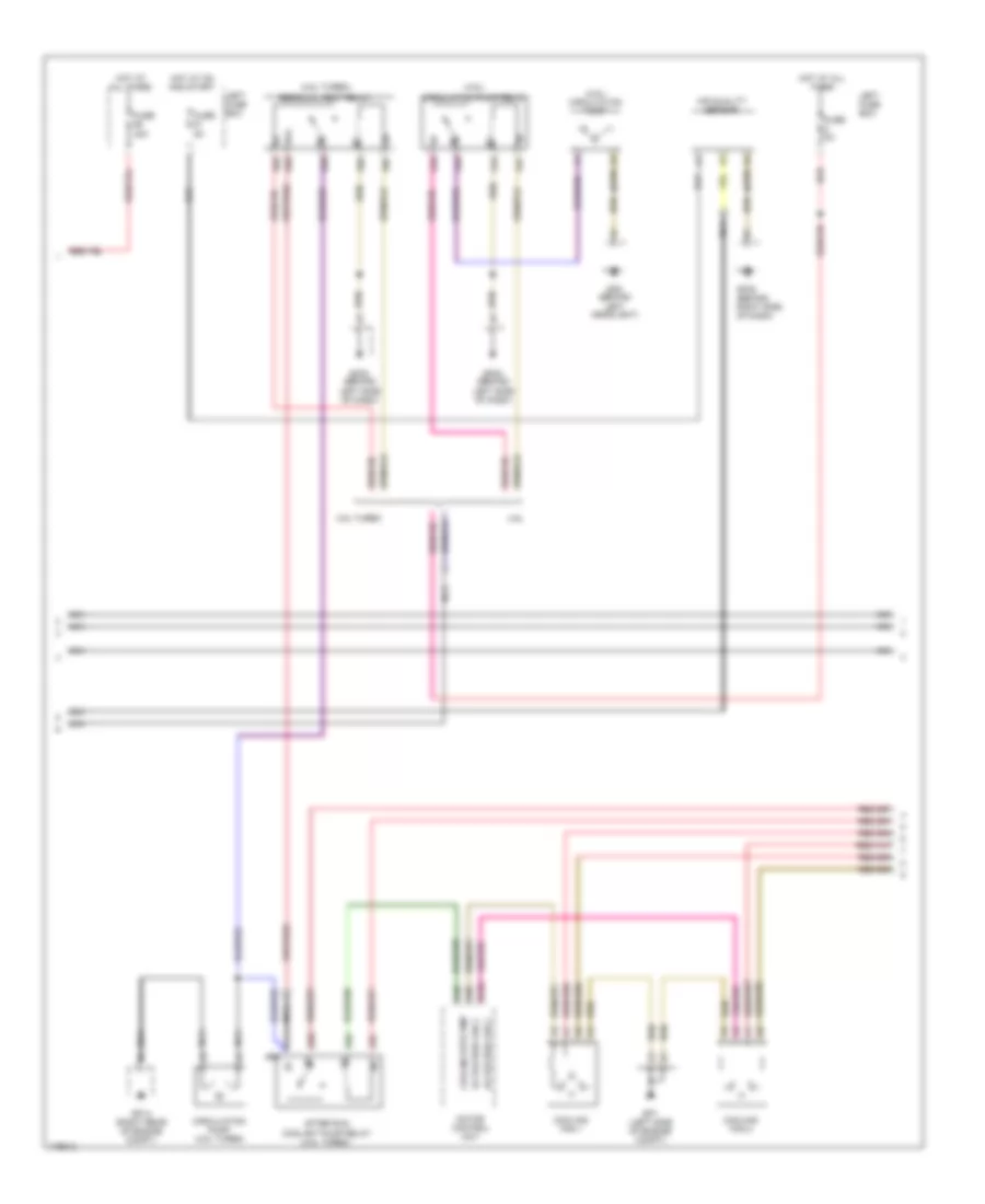
Automotive Electricians Portal FZCOList of elements for Automatic A/C Wiring Diagram, Dual A/C Wiring Diagram (2 of 4) for Porsche Cayenne Turbo 2003:
- (behind right side of dash)
- Blower control unit
- Defrost drive motor
- E-box
- Evaporator temperature sensor
- Front blower motor
- Fuse 15a
- Gp22
- Hot at all times
- Left footwell drive motor
- Left output sensor
- Left side drive motor
- Motor
- Nca
- Pwm-a
- Right temperature drive motor
- Sun sensor
- Term 31
- Vcc
- Volt feedback
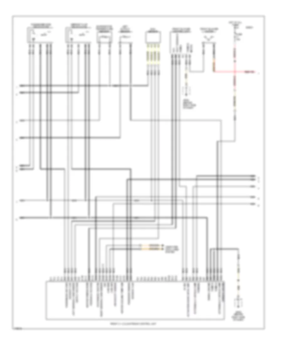
Automatic A/C Wiring Diagram, Dual A/C Wiring Diagram (3 of 4) for Porsche Cayenne Turbo 2003
 https://portal-diagnostov.com/license.html
Automotive Electricians Portal FZCO
Automotive Electricians Portal FZCO
https://portal-diagnostov.com/license.html
https://portal-diagnostov.com/license.html
Automotive Electricians Portal FZCO
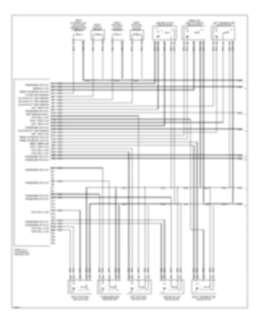
Automotive Electricians Portal FZCOList of elements for Automatic A/C Wiring Diagram, Dual A/C Wiring Diagram (3 of 4) for Porsche Cayenne Turbo 2003:
- (4.5l turbo)
- (4.5l)
- (4.5l) circulation pump
- (behind right side of dash)
- 4.5l
- 4.5l turbo
- 87a
- A48
- A4a
- A4c
- A4d
- A4e
- A5a
- A5c
- A5d
- A5e
- A66
- A8a
- A8b
- A8c
- A8d
- A8e
- Actuation fan 2
- After run coolant pump relay (4.5l turbo)
- Air quality sensor
- B104
- Circulation pump (4.5l turbo)
- Circulation pump relay
- Cooling fan 1
- Cooling fan 2
- Cooling wtr pmp
- Fuse 40a
- Fuse 5a
- Gp1 (left side of engine compt)
- Gp14 (right rear of engine compt)
- Gp22
- Gp23 (behind left side of dash)
- Gp5 (behind left headlight)
- Hot at all times
- Hot at on and start
- Left fuse box
- Motor control unit
- Nca
- Red
- Residual heat relay
Automatic A/C Wiring Diagram, Dual A/C Wiring Diagram (4 of 4) for Porsche Cayenne Turbo 2003
 https://portal-diagnostov.com/license.html
Automotive Electricians Portal FZCO
Automotive Electricians Portal FZCO
https://portal-diagnostov.com/license.html
https://portal-diagnostov.com/license.html
Automotive Electricians Portal FZCO
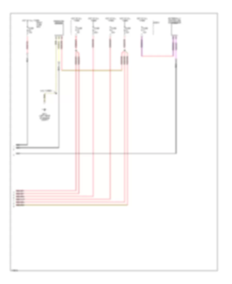
Automotive Electricians Portal FZCOList of elements for Automatic A/C Wiring Diagram, Dual A/C Wiring Diagram (4 of 4) for Porsche Cayenne Turbo 2003:
- (4.5l turbo)
- E-box
- Externally controlled compressor
- Fuse 10a
- Fuse 30a
- Fuse 5a
- Fuse 60a
- Gp11 (left rear of engine compt)
- Hot at all times
- Nca
- Pressure sensor
- Right fuse box
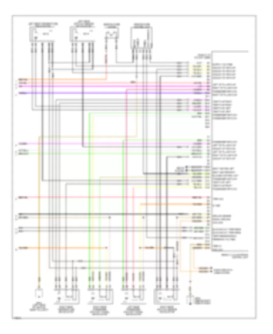
Automatic A/C Wiring Diagram, Front & Rear A/C (1 of 5) for Porsche Cayenne Turbo 2003
 https://portal-diagnostov.com/license.html
Automotive Electricians Portal FZCO
Automotive Electricians Portal FZCO
https://portal-diagnostov.com/license.html
https://portal-diagnostov.com/license.html
Automotive Electricians Portal FZCO
Automotive Electricians Portal FZCOList of elements for Automatic A/C Wiring Diagram, Front & Rear A/C (1 of 5) for Porsche Cayenne Turbo 2003:
- A10
- A11
- A12
- A13
- A14
- A15
- A16
- A17
- A18
- A19
- A20
- A21
- A22
- A23
- A24
- B10
- B11
- B12
- B13
- B14
- B15
- B16
- B17
- B18
- B19
- B20
- B21
- B22
- B23
- B24
- Blowing out temp sensor
- Center outlet drive motor
- Defrost flap
- Footwell flap
- Fresh air recirc air flap
- Fresh air/ circulating air drive motor
- Front 2 + 2 climatronic control unit
- Intake temp sensor
- Left footwell drive motor
- Left temp flap
- Left temperature drive motor
- Nca
- Passenger air flow
- Passenger side drive motor
- Rear evaporative air intake temperature sensor
- Right footwell drive motor
- Right footwell output sensor
- Right output sensor
- Right temp flap
- Right temp flap right temp flap
- Right temperature drive motor
- Temp sensor signal
Automatic A/C Wiring Diagram, Front & Rear A/C (2 of 5) for Porsche Cayenne Turbo 2003
 https://portal-diagnostov.com/license.html
Automotive Electricians Portal FZCO
Automotive Electricians Portal FZCO
https://portal-diagnostov.com/license.html
https://portal-diagnostov.com/license.html
Automotive Electricians Portal FZCO
Automotive Electricians Portal FZCOList of elements for Automatic A/C Wiring Diagram, Front & Rear A/C (2 of 5) for Porsche Cayenne Turbo 2003:
- (behind right side of dash)
- 5v ref
- Actuation blwr cntrl unit
- Air quality sensor
- Aux
- C10
- C11
- C12
- C13
- C14
- C15
- C16
- C17
- C18
- C19
- C20
- C21
- C22
- C23
- C24
- Can high
- Can low
- Computer data lines system
- D10
- D11
- D12
- Defrost flap
- Defrost flap drive motor
- E-box
- E10
- E11
- E12
- Evaporator temperature sensor
- Externally cntrld comp
- Feedback voltage
- Front 2 + 2 climatronic control unit
- Front blower control unit
- Front blower motor
- Fuse 15a
- Gp22
- Gp22 (behind right side of dash)
- Heated windscreen
- Hot at all times
- Left output sensor
- Left sidewall sun sensor
- Motor
- Nca
- Passenger air flow
- Passenger side drive motor
- Pressure sensor
- Pwm-a
- Right sidewall sun sensor
- Sensor ground
- Signal ground
- Stationary heater
- Sun sensor
- Term 30a
- Term 31
- Vcc
- Volt feedback
- Water cooling temp sen
Automatic A/C Wiring Diagram, Front & Rear A/C (3 of 5) for Porsche Cayenne Turbo 2003
 https://portal-diagnostov.com/license.html
Automotive Electricians Portal FZCO
Automotive Electricians Portal FZCO
https://portal-diagnostov.com/license.html
https://portal-diagnostov.com/license.html
Automotive Electricians Portal FZCO
Automotive Electricians Portal FZCOList of elements for Automatic A/C Wiring Diagram, Front & Rear A/C (3 of 5) for Porsche Cayenne Turbo 2003:
- (4.5l turbo)
- (4.5l)
- (4.5l) circulation pump
- (behind right side of dash)
- 4.5l
- 4.5l turbo
- 87a
- A48
- A4a
- A4c
- A4d
- A4e
- A5a
- A5c
- A5d
- A5e
- A66
- A8a
- A8b
- A8c
- A8d
- A8e
- Actuation fan 2
- After run coolant pump relay (4.5l turbo)
- Air quality sensor
- B104
- Circulation pump (4.5l turbo)
- Circulation pump relay
- Cooling fan 1
- Cooling fan 2
- Cooling wtr pmp
- Fuse 40a
- Fuse 5a
- Gp1 (left side of engine compt)
- Gp14 (right rear of engine compt)
- Gp22
- Gp23 (behind left side of dash)
- Gp5 (behind left headlight)
- Hot at all times
- Hot at on and start
- Left fuse box
- Motor control unit
- Nca
- Red
- Residual heat relay
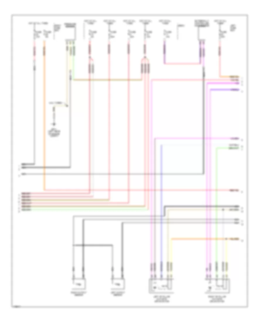
Automatic A/C Wiring Diagram, Front & Rear A/C (4 of 5) for Porsche Cayenne Turbo 2003
 https://portal-diagnostov.com/license.html
Automotive Electricians Portal FZCO
Automotive Electricians Portal FZCO
https://portal-diagnostov.com/license.html
https://portal-diagnostov.com/license.html
Automotive Electricians Portal FZCO
Automotive Electricians Portal FZCOList of elements for Automatic A/C Wiring Diagram, Front & Rear A/C (4 of 5) for Porsche Cayenne Turbo 2003:
- (4.5l turbo)
- E-box
- Externally controlled compressor
- Fuse 10a
- Fuse 30a
- Fuse 40a
- Fuse 5a
- Fuse 60a
- Gp11 (left rear of engine compt)
- Hot at all times
- Left "b" pillar outlets drive motor
- Left fuse box
- Left output sensor
- Nca
- Pressure sensor
- Right "b" pillar outlets drive motor
- Right fuse box
- Right output sensor
Automatic A/C Wiring Diagram, Front & Rear A/C (5 of 5) for Porsche Cayenne Turbo 2003
 https://portal-diagnostov.com/license.html
Automotive Electricians Portal FZCO
Automotive Electricians Portal FZCO
https://portal-diagnostov.com/license.html
https://portal-diagnostov.com/license.html
Automotive Electricians Portal FZCO
Automotive Electricians Portal FZCOList of elements for Automatic A/C Wiring Diagram, Front & Rear A/C (5 of 5) for Porsche Cayenne Turbo 2003:
- (pins a1 to a12 not used)
- 5v ref
- Amount of air flap
- B10
- B11
- B12
- B13
- B14
- B15
- B16
- B17
- B18
- B19
- B20
- Blower control unit
- Blowing out temp sens
- C10
- C11
- C12
- C13
- C14
- C15
- C16
- Can high
- Can low
- Computer data lines system
- D12
- D14
- D15
- D16
- Feedback voltage
- Gp22 (behind right side of dash)
- Gp41 (left rear of vehicle, near taillight)
- Ground sensor
- Left "b" pillar flap
- Left rear air flow sensor drive motor
- Left rear passenger air flow tunnel drive motor
- Left rear temperature drive motor
- Motor
- Nca
- Passenger air flow
- Pwm-a
- Rear 2 + 2 climatronic control unit
- Rear blower control unit
- Rear blower motor
- Right "b" pillar flap
- Right rear air flow sensor drive motor
- Right rear passenger air flow tunnel drive motor
- Right rear temperature drive motor
- Seat heater left
- Seat heater right
- Seats system
- Signal ground
- Temp flap left
- Temp flap right
- Temp sensor signal
- Term 30a
- Term 31
- Vcc
- Volt feedback

 Čeština
 Dansk
Dansk Deutsch
 Ελληνικά
 English
 English
 Español
 Suomi
Suomi Français
 Français
 עברית
עברית Hrvatski
 Magyar
 Italiano
 日本語
日本語 한국어
한국어 Nederlands
 Polski
 Português
 Português
 Română
 Русский
 Slovenčina
 Slovenščina
 Svenska
 中文 (中国)
