ANTI-LOCK BRAKES
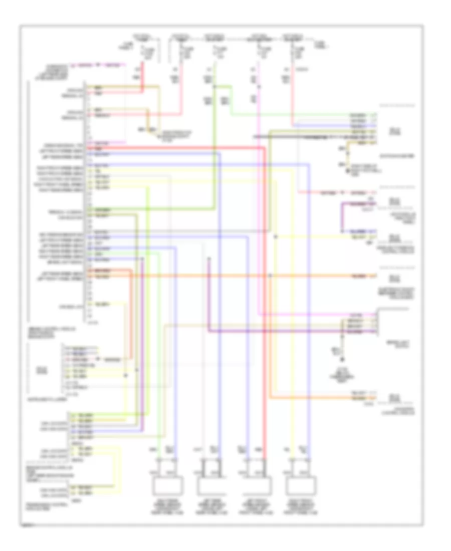
Anti-lock Brakes Wiring Diagram, with Automatic Stability Control, with IKE for BMW 528i 2000
 https://portal-diagnostov.com/license.html
Automotive Electricians Portal FZCO
Automotive Electricians Portal FZCO
https://portal-diagnostov.com/license.html
https://portal-diagnostov.com/license.html
Automotive Electricians Portal FZCO
Automotive Electricians Portal FZCO
List of elements for Anti-lock Brakes Wiring Diagram, with Automatic Stability Control, with IKE for BMW 528i 2000:
- (right front of engine compt) x1106
- (right side of right footwell) x492
- Abs/asc control module (right side of engine compt)
- Asc passive sensor sig
- Brake light signal
- Brake light switch
- Can bus high
- Can bus low
- Can high data
- Can low data
- Diagnosis signal txd
- Diagnostic connector (left rear side of engine compt)
- Electronic shock absorber control module (edc)
- Engine control module (dme) (left rear side of engine compt)
- Fuse f108 50a
- Fuse f17 10a
- Fuse f30 25a
- Fuse f32 25a
- Fuse f41 5a
- Fuse panel 1
- Fuse panel 4
- Ground
- Headlight widening control module
- Hot acc, run or start
- Hot at all times
- Hot in run or start
- Instrument cluster
- Integrated instrument cluster control module
- Left front speed sens
- Left front speed sensor (inside left front wheel hub)
- Left front wheel speed
- Left rear speed sens
- Left rear speed sensor (inside left rear wheel hub)
- Light module (right kick panel)
- Malfunction ind signal
- Navigation control module
- Nca
- Red
- Right front speed sens
- Right front speed sensor (inside right front wheel hub)
- Right front wheel speed
- Right rear speed sens
- Right rear speed sensor (inside right rear wheel hub)
- Solid state
- Switching center
- Terminal 15 signal
- Terminal 30
- Transmission control module (ags)
- X10015
- X10113
- X10114
- X10117
- X1108 (below passenger's seat)
- X1170
- X1312
- X16
- X27
- X38
- X60002
- X60004
- X8600
- X991
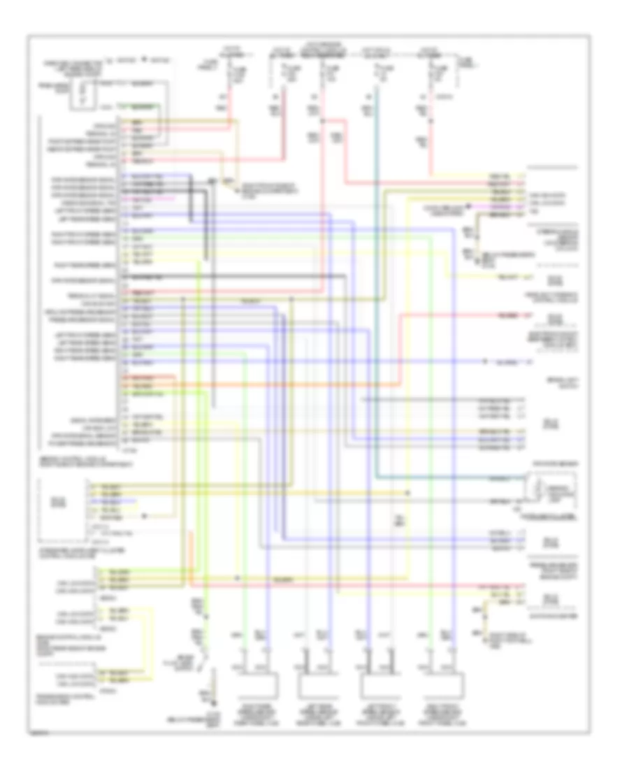
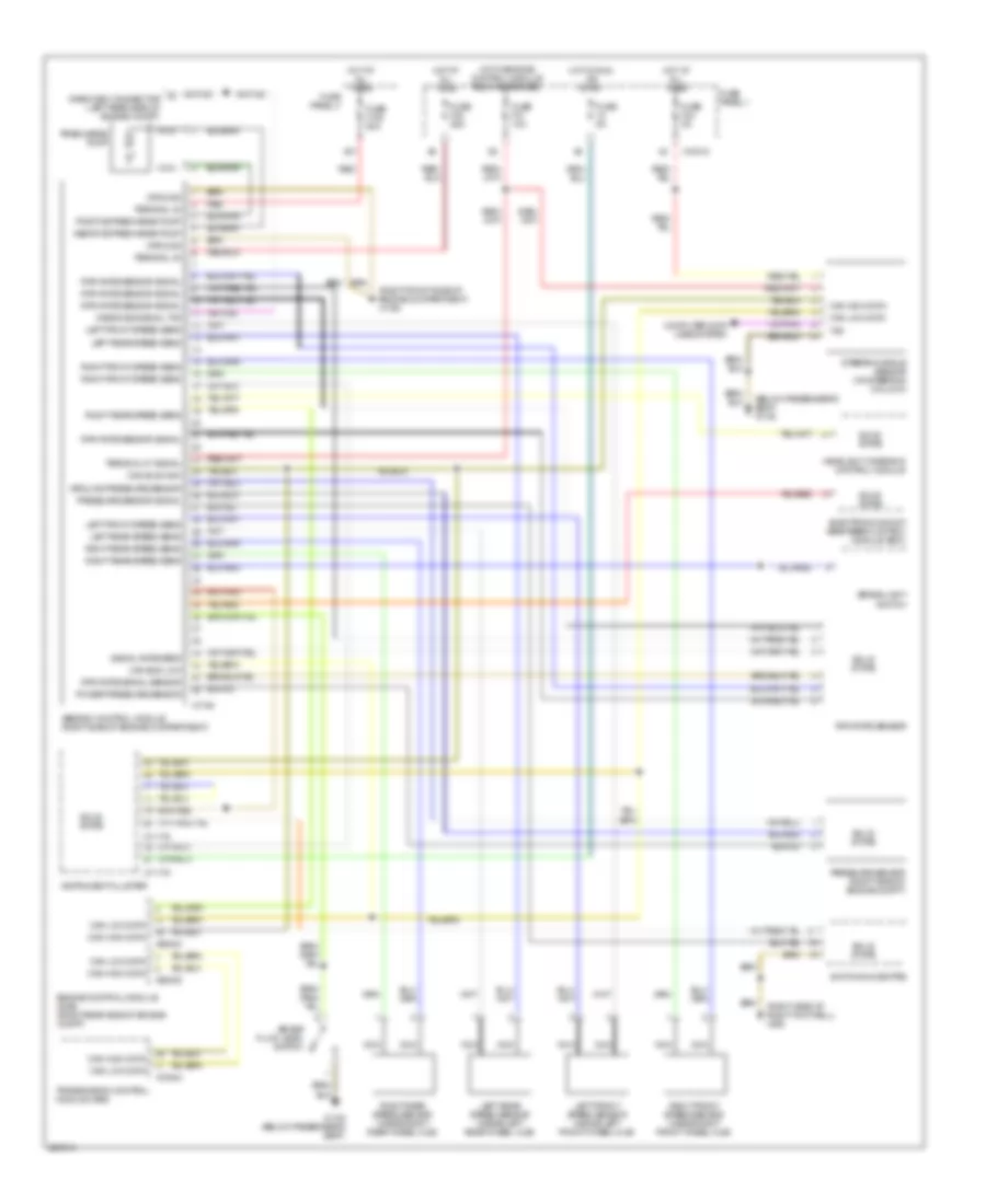
Anti-lock Brakes Wiring Diagram, with Automatic Stability Control, without IKE for BMW 528i 2000
 https://portal-diagnostov.com/license.html
Automotive Electricians Portal FZCO
Automotive Electricians Portal FZCO
https://portal-diagnostov.com/license.html
https://portal-diagnostov.com/license.html
Automotive Electricians Portal FZCO
Automotive Electricians Portal FZCOList of elements for Anti-lock Brakes Wiring Diagram, with Automatic Stability Control, without IKE for BMW 528i 2000:
- (right front of engine compt) x1106
- (right side of right footwell) x492
- Abs/asc control module (right side of engine compt)
- Asc passive sensor sig
- Brake light signal
- Brake light switch
- Can bus high
- Can bus low
- Can high data
- Can low data
- Diagnosis signal txd
- Diagnostic connector (left rear side of engine compt)
- Electronic shock absorber control module (edc)
- Engine control module (dme) (left rear side of engine compt)
- Fuse f108 50a
- Fuse f17 10a
- Fuse f30 25a
- Fuse f32 25a
- Fuse f41 5a
- Fuse panel 1
- Fuse panel 4
- Ground
- Headlight widening control module
- Hot acc, run or start
- Hot at all times
- Hot in run or start
- Instrument cluster
- Left front speed sens
- Left front speed sensor (inside left front wheel hub)
- Left front wheel speed
- Left rear speed sens
- Left rear speed sensor (inside left rear wheel hub)
- Light module (right kick panel)
- Malfunction ind signal
- Navigation control module
- Nca
- Red
- Right front speed sens
- Right front speed sensor (inside right front wheel hub)
- Right front wheel speed
- Right rear speed sens
- Right rear speed sensor (inside right rear wheel hub)
- Solid state
- Switching center
- Terminal 15 signal
- Terminal 30
- Transmission control module (ags)
- X10015
- X10117
- X1108 (below passenger's seat)
- X11175
- X11176
- X1170
- X1312
- X27
- X38
- X60002
- X60004
- X8600
- X991
Anti-lock Brakes Wiring Diagram, with Dynamic Stability Control, with IKE for BMW 528i 2000
 https://portal-diagnostov.com/license.html
Automotive Electricians Portal FZCO
Automotive Electricians Portal FZCO
https://portal-diagnostov.com/license.html
https://portal-diagnostov.com/license.html
Automotive Electricians Portal FZCO
Automotive Electricians Portal FZCOList of elements for Anti-lock Brakes Wiring Diagram, with Dynamic Stability Control, with IKE for BMW 528i 2000:
- (below passenger's seat) x1108
- (right front side of engine compartment) x1106
- (right side of right footwell) x492
- Abs/dsc control module (right side of engine compartment)
- Abs/dsc indicator lamp
- Brake fluid level switch
- Brake light switch
- Can bus high
- Can bus low
- Can high data
- Can low data
- Computer data lines system
- Diagnosic connector (left rear side of engine compt)
- Diagnosis signal txd
- Electronic shock absorber control module (edc)
- Engine control module (dme) (right rear side of engine compt)
- Fuse 5a
- Fuse f108 50a
- Fuse f24 5a
- Fuse f30 25a
- Fuse f31 10a
- Fuse panel 1
- Fuse panel 4
- Ground
- Ground pressure sensor
- Headlight widening control module
- Hot at all times
- Hot in run or start
- Hot w/engine control module relay energized
- Instrument cluster
- Integrated instrument cluster control module (ike)
- Left front speed sens
- Left front speed sensor (inside left front wheel hub)
- Left rear speed sens
- Left rear speed sensor (inside left rear wheel hub)
- Nca
- Positive precharge pump
- Power pressure sensor
- Precharge pump
- Pressure sensor (right side of engine compt)
- Pressure sensor signal
- Red
- Right front speed sens
- Right front speed sensor (inside right front wheel hub)
- Right rear speed sens
- Right rear speed sensor (inside right rear wheel hub)
- Rpm rate sensor
- Rpm rate sensor signal
- Rpm rate signal sensor
- Signal rate sens
- Solid state
- Steering angle sensor (on steering column)
- Switching center
- Terminal 30
- Terminal 87 signal
- Transmission control module (ags)
- Txd
- X10015
- X10113
- X10114
- X1108 (below passenger's seat)
- X16
- X1746
- X27
- X60002
- X60004
- X70004
Anti-lock Brakes Wiring Diagram, with Dynamic Stability Control, without IKE for BMW 528i 2000
 https://portal-diagnostov.com/license.html
Automotive Electricians Portal FZCO
Automotive Electricians Portal FZCO
https://portal-diagnostov.com/license.html
https://portal-diagnostov.com/license.html
Automotive Electricians Portal FZCO
Automotive Electricians Portal FZCOList of elements for Anti-lock Brakes Wiring Diagram, with Dynamic Stability Control, without IKE for BMW 528i 2000:
- (below passenger's seat) x1108
- (right front side of engine compartment) x1106
- (right side of right footwell) x492
- Abs/dsc control module (right side of engine compartment)
- Brake fluid level switch
- Brake light switch
- Can bus high
- Can bus low
- Can high data
- Can low data
- Computer data lines system
- Diagnosic connector (left rear side of engine compt)
- Diagnosis signal txd
- Electronic shock absorber control module (edc)
- Engine control module (dme) (right rear side of engine compt)
- Fuse 5a
- Fuse f108 50a
- Fuse f24 5a
- Fuse f30 25a
- Fuse f31 10a
- Fuse panel 1
- Fuse panel 4
- Ground
- Ground pressure sensor
- Headlight widening control module
- Hot at all times
- Hot in run or start
- Hot w/engine control module relay energized
- Instrument cluster
- Left front speed sens
- Left front speed sensor (inside left front wheel hub)
- Left rear speed sens
- Left rear speed sensor (inside left rear wheel hub)
- Nca
- Positive precharge pump
- Power pressure sensor
- Precharge pump
- Pressure sensor (right side of engine compt)
- Pressure sensor signal
- Red
- Right front speed sens
- Right front speed sensor (inside right front wheel hub)
- Right rear speed sens
- Right rear speed sensor (inside right rear wheel hub)
- Rpm rate sensor
- Rpm rate sensor signal
- Rpm rate signal sensor
- Signal rate sens
- Solid state
- Steering angle sensor (on steering column)
- Switching centre
- Terminal 30
- Terminal 87 signal
- Transmission control module (ags)
- Txd
- X10015
- X1108 (below passenger's seat)
- X11175
- X11176
- X1746
- X27
- X60002
- X60004
- X70004

 Čeština
 Dansk
Dansk Deutsch
 Ελληνικά
 English
 English
 Español
 Suomi
Suomi Français
 Français
 עברית
עברית Hrvatski
 Magyar
 Italiano
 日本語
日本語 한국어
한국어 Nederlands
 Polski
 Português
 Português
 Română
 Русский
 Slovenčina
 Slovenščina
 Svenska
 中文 (中国)
