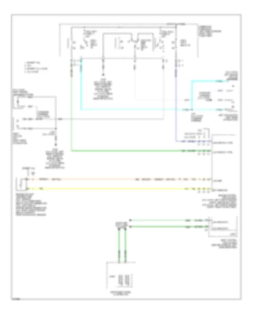
COOLING FAN
Cooling Fan Wiring Diagram, with Hybrid for Saturn Aura XR 2008
 https://portal-diagnostov.com/license.html
Automotive Electricians Portal FZCO
Automotive Electricians Portal FZCO
https://portal-diagnostov.com/license.html
https://portal-diagnostov.com/license.html
Automotive Electricians Portal FZCO
Automotive Electricians Portal FZCO
List of elements for Cooling Fan Wiring Diagram, with Hybrid for Saturn Aura XR 2008:
- (behind top left rear seat back) g302
- (front center of generator battery) generator battery vent fan
- (lower left side of engine, near a/c compressor) starter generator control module (sgcm) cooling pump
- (middle rear of engine) heater coolant pump
- (right front of transmission, below sgcm) transmission pump
- A trans pump driver error
- A12
- B pump control
- B10
- Bare
- Bas pmp fuse 5 20a
- Battery positive vol
- C pump motor vol
- C12
- C2 interlock loop sig
- Computer data lines system
- Coolant pump control
- Driver error
- Emission 2 fuse 5 10a
- F trans pump low ref
- Fan control
- Fan tach feedback
- G trans pump high ref
- G107 (right front of engine)
- G114
- Gen batt temp sens 1a control
- Gen batt temp sens 1b control
- Gen batt temp sens 2a control
- Gen batt temp sens 2b control
- Gen batt temp sens 3a control
- Gen batt temp sens 3b control
- Generator battery 1
- Generator battery 2
- Generator battery 3
- Generator battery assembly
- Generator battery disconnect control module
- Generator battery temperature sensor 1a
- Generator battery temperature sensor 1b
- Generator battery temperature sensor 2a
- Generator battery temperature sensor 2b
- Generator battery temperature sensor 3a
- Generator battery temperature sensor 3b
- Gnd
- Ground
- H trans pump sw control
- High speed gmlan serial data +
- High speed gmlan serial data -
- High vol
- Hot at all times
- Hot in run or start
- Ign 1 ecm ign bas ign fuse 3 10a
- Ignition 1 vol
- Interlock loop sig
- Low ref
- Maf injectors bas pmps fuse 5 20a
- Motor vol
- Nca
- Pnk
- Power
- Power distribution system
- Pump
- Pump control
- Pump driver (left front of engine compt, behind sgcm)
- Rear fuse block (behind left rear wheel well)
- Red
- Starter generator control module (sgcm) (left front engine compt)
- Tan
- Trans pmp mtr relay
- Trans pump
- Trans pump rly coil control
- Underhood fuse block (left side of engine compt, next to battery)
Cooling Fan Wiring Diagram, without Hybrid for Saturn Aura XR 2008
 https://portal-diagnostov.com/license.html
Automotive Electricians Portal FZCO
Automotive Electricians Portal FZCO
https://portal-diagnostov.com/license.html
https://portal-diagnostov.com/license.html
Automotive Electricians Portal FZCO
Automotive Electricians Portal FZCOList of elements for Cooling Fan Wiring Diagram, without Hybrid for Saturn Aura XR 2008:
- (2.4l (vin 5)) left engine cooling fan diode
- (2.4l (vin 5)) right engine cooling fan diode
- (in engine harness) (2.4l (vin 5)) j150
- (in engine harness) (2.4l (vin 5)) j153
- (or 2761)
- (or tan)
- 2.4l (vin b)
- 3.5l
- 3.6l
- 3.6l & 2.4l (vin 5)
- 87a
- A11
- B10
- Body control module (bcm) (center console, left side near dash)
- Computer data lines system
- Cool fan 1 fuse 17 30a
- Cool fan 2 fuse 18 30a
- Cool/ fan 1 relay
- Cool/ fan 2 relay 30
- Cool/fan ser/ par relay
- Ect sens sig
- Engine control module (ecm) (2.4l (vin 5): left side of engine compt, behind battery) (3.5l & 3.6l: left side of engine compt, front of battery)
- Engine coolant temperature (ect) sensor (3.5l: in cylinder head, below coolant reservoir) (3.6l: left side of engine, behind generator) (2.4l: right side of engine, below camshaft position exhaust sensor)
- Except 2.4l (vin b)
- Except 3.5l
- Except 3.6l
- G106 (2.4l (vin b): left rear of engine) (3.5l: rear of engine, above oil filter) (2.4l (vin 5): rear of engine, near pnp switch)
- High spd rly ctrl
- Hot at all times
- Instrument panel cluster (ipc)
- J151 (2.4l (vin 5)) (in engine harness)
- J152 (2.4l (vin 5))
- Left cooling fan (left rear of radiator)
- Logic
- Low ref
- Low spd data
- Low spd rly ctrl
- Low spd ser data
- Right cooling fan (right rear of radiator)
- Ser data low spd
- Tan
- Underhood fuse block (left side of engine compt, next to battery)

 Čeština
 Dansk
Dansk Deutsch
 Ελληνικά
 English
 English
 Español
 Suomi
Suomi Français
 Français
 עברית
עברית Hrvatski
 Magyar
 Italiano
 日本語
日本語 한국어
한국어 Nederlands
 Polski
 Português
 Português
 Română
 Русский
 Slovenčina
 Slovenščina
 Svenska
 中文 (中国)
