ANTI-LOCK BRAKES
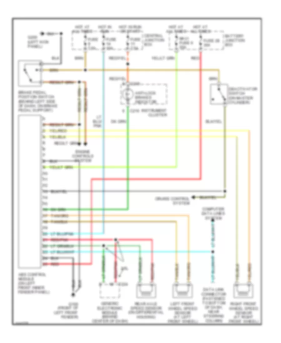
Anti-lock Brake Wiring Diagrams for Mazda B4000 Dual Sport 2001
 https://portal-diagnostov.com/license.html
Automotive Electricians Portal FZCO
Automotive Electricians Portal FZCO
https://portal-diagnostov.com/license.html
https://portal-diagnostov.com/license.html
Automotive Electricians Portal FZCO
Automotive Electricians Portal FZCO
List of elements for Anti-lock Brake Wiring Diagrams for Mazda B4000 Dual Sport 2001:
- 2.5l
- Abs control module (on left front inner fender panel)
- Anti-lock brakes indicator
- Battery junction box
- Brake pedal position switch (behind left side of dash, on brake pedal support)
- C215
- C216
- Central junction box
- Computer data lines system
- Cruise control system
- Data link connector (fastened to bottom of dash, near steering column)
- Deactivator switch (on master cylinder)
- Engine controls system
- Fuse 10a
- Fuse 28 30a
- Fuse 7.5a
- G100 (front of left front fender)
- G200 (left kick panel)
- Generic electronic module (behind center of dash)
- Hot at all times
- Hot in run
- Hot in run or start
- Instrument cluster
- Left front wheel speed sensor (at left front wheel)
- Maxi fuse 6 50a
- Rear axle speed sensor (on differential housing)
- Red
- Red/pnk
- Right front wheel speed sensor (at right front wheel)
- T224
 Čeština
 Dansk
Dansk Deutsch
 Ελληνικά
 English
 English
 Español
 Suomi
Suomi Français
 Français
 עברית
עברית Hrvatski
 Magyar
 Italiano
 日本語
日本語 한국어
한국어 Nederlands
 Polski
 Português
 Português
 Română
 Русский
 Slovenčina
 Slovenščina
 Svenska
 中文 (中国)
 Türkçe
