ANTI-LOCK BRAKES
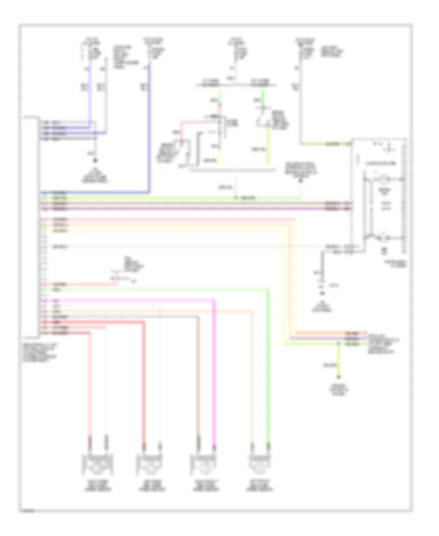
Anti-lock Brakes Wiring Diagram for Mazda Protege Mazdaspeed 2003
 https://portal-diagnostov.com/license.html
Automotive Electricians Portal FZCO
Automotive Electricians Portal FZCO
https://portal-diagnostov.com/license.html
https://portal-diagnostov.com/license.html
Automotive Electricians Portal FZCO
Automotive Electricians Portal FZCO
List of elements for Anti-lock Brakes Wiring Diagram for Mazda Protege Mazdaspeed 2003:
- A/t
- Abs fuse 60a
- Abs hydraulic unit control module (at left rear corner of engine compartment)
- Abs ind
- Brake ind
- Brake switch (behind left side of dash)
- Cruise control, exterior lights,
- Data link connector (dlc) (at left rear corner of engine compt)
- Engine controls system
- Engine controls systems
- Engine fuse 10a
- G6 (at left front inner fender panel)
- G9 (at left kick panel)
- Hot at all times
- Hot in run or start
- Instrument cluster
- J/c 04
- Joint box (behind left kick panel)
- Left front abs wheel speed sensor
- Left rear abs wheel speed sensor
- Main fuse block (on left front inner fender panel)
- Meter fuse 10a
- Microcomputer
- Noise filter
- Pcm (behind right side of dash)
- Red
- Right front abs wheel speed sensor
- Right rear abs wheel speed sensor
- Stop fuse 15a
- W/ turbo changer
- W/o turbo changer
 Čeština
 Dansk
Dansk Deutsch
 Ελληνικά
 English
 English
 Español
 Suomi
Suomi Français
 Français
 עברית
עברית Hrvatski
 Magyar
 Italiano
 日本語
日本語 한국어
한국어 Nederlands
 Polski
 Português
 Português
 Română
 Русский
 Slovenčina
 Slovenščina
 Svenska
 中文 (中国)
 Türkçe
