ANTI-LOCK BRAKES
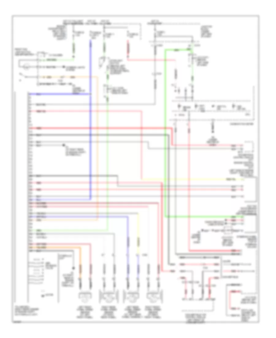
Anti-lock Brakes Wiring Diagram for Mitsubishi Eclipse Spyder GT 2012
 https://portal-diagnostov.com/license.html
Automotive Electricians Portal FZCO
Automotive Electricians Portal FZCO
https://portal-diagnostov.com/license.html
https://portal-diagnostov.com/license.html
Automotive Electricians Portal FZCO
Automotive Electricians Portal FZCO
List of elements for Anti-lock Brakes Wiring Diagram for Mitsubishi Eclipse Spyder GT 2012:
- Abs solenoid valve
- Anti lock ind
- Asc off ind
- Asc/tcl ind
- B-18
- Brake ind
- C-203
- C-215
- C-23
- C-24
- C-26
- Combination meter
- Computer data lines system
- Convertible
- Convertible top control module (left front of luggage compt)
- Coupe
- Cpu
- D-45
- Data link connector (below left
- Engine compartment relay box (left side of engine compt)
- Front fog lamp switch/ asc off switch
- Fuse 11 7.5a
- Fuse 2 7.5a
- Fuse 20 7.5a
- Fuse 22 10a
- Fusible link 3 60a
- G & yaw rate sensor (under rear of center console)
- G1 (at right rear of engine compt, on firewall)
- G3 (under center of dash)
- Hot at all times
- Hot in on or start
- Hot w/ taillight relay energized
- Hydraulic unit
- Interior lights system
- J/c 1 (c-28) (behind left side of dash)
- J/c 2 (c-01) (behind left side of dash)
- J/c 3 (c-03) (behind left side of dash)
- Junction block (under left end of dash)
- Left front wheel speed sensor (at left front wheel)
- Left rear wheel speed sensor (at left rear wheel assembly)
- Motor m
- Nca
- Powertrain control module (a/t) engine control module (m/t) (left side of engine compt, forward of relay box)
- Red
- Right front wheel speed sensor (at right front wheel)
- Right rear wheel speed sensor (at right rear wheel)
- Side of dash)
- Steering wheel sensor (top of steering column)
- Stoplight switch (behind left side of dash, on brake pedal support)
- Tcl/asc-ecu (right rear corner of engine compt, on hydraulic unit)
- W/ halogen
- W/ hid
 Čeština
 Dansk
Dansk Deutsch
 Ελληνικά
 English
 English
 Español
 Suomi
Suomi Français
 Français
 עברית
עברית Hrvatski
 Magyar
 Italiano
 日本語
日本語 한국어
한국어 Nederlands
 Polski
 Português
 Português
 Română
 Русский
 Slovenčina
 Slovenščina
 Svenska
 中文 (中国)
 Türkçe
