ANTI-LOCK BRAKES
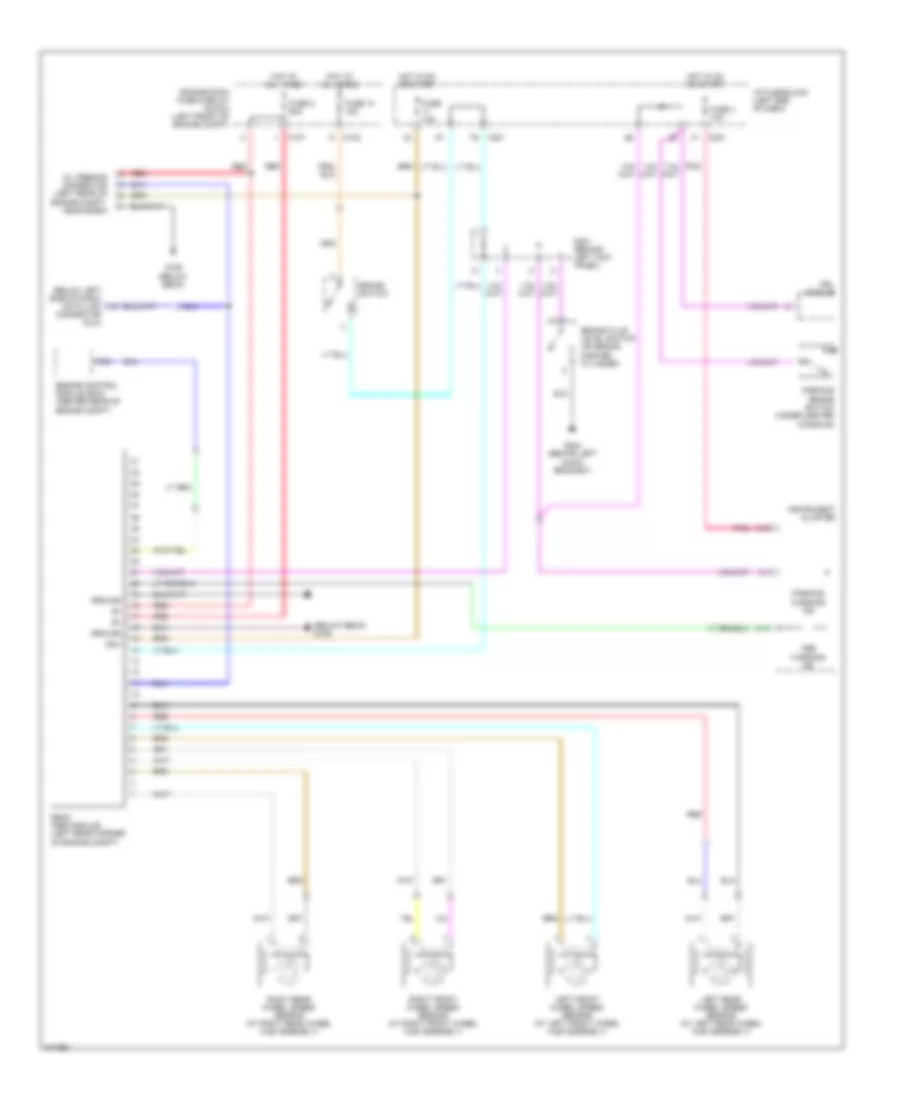
Anti-lock Brakes Wiring Diagram for Suzuki Reno 2006
 https://portal-diagnostov.com/license.html
Automotive Electricians Portal FZCO
Automotive Electricians Portal FZCO
https://portal-diagnostov.com/license.html
https://portal-diagnostov.com/license.html
Automotive Electricians Portal FZCO
Automotive Electricians Portal FZCO
List of elements for Anti-lock Brakes Wiring Diagram for Suzuki Reno 2006:
- (below ebcm) g106
- (below left side of dash) data link
- A13
- A19
- Abs
- Brake fluid level switch (on brake master cylinder)
- Brake switch
- C102
- C107
- C201
- C64
- Connector (dlc)
- Drl module
- Ebcm (abs module) (left rear corner of engine compt)
- Engine control module (ecm) (center rear of engine compt)
- Engine room fuse & relay block (left front of engine compt)
- Fuse 10a
- Fuse 13 15a
- Fuse 2 60a
- Fuse 4 10a
- G106 (below ebcm)
- G204 (behind left audio bracket)
- Ground
- Hot at all times
- Hot in on or start
- I/p fuse block (left end of dash)
- Ign+
- Instrument cluster
- Left front wheel speed sensor (at left front wheel hub assembly)
- Left rear wheel speed sensor (at left rear wheel hub assembly)
- Oil feeding connector (left rear of engine compt, near ecbm)
- Parking
- Parking brake switch (under center console)
- Pnk
- Red
- Right front wheel speed sensor (at right front wheel hub assembly)
- Right rear wheel speed sensor (at right rear wheel hub assembly)
- S301 (behind left kick panel)
- Warning ind
 Čeština
 Dansk
Dansk Deutsch
 Ελληνικά
 English
 English
 Español
 Suomi
Suomi Français
 Français
 עברית
עברית Hrvatski
 Magyar
 Italiano
 日本語
日本語 한국어
한국어 Nederlands
 Polski
 Português
 Português
 Română
 Русский
 Slovenčina
 Slovenščina
 Svenska
 中文 (中国)
 Türkçe
