ENGINE PERFORMANCE
3.5L
3.5L, Engine Performance Wiring Diagram (1 of 4) for Nissan Pathfinder SE 2004
 https://portal-diagnostov.com/license.html
Automotive Electricians Portal FZCO
Automotive Electricians Portal FZCO
https://portal-diagnostov.com/license.html
https://portal-diagnostov.com/license.html
Automotive Electricians Portal FZCO
Automotive Electricians Portal FZCO
List of elements for 3.5L, Engine Performance Wiring Diagram (1 of 4) for Nissan Pathfinder SE 2004:
- (upper left kick panel) m157
- 10u
- 17u
- Avcc
- Avcc2
- Combination meter
- Computer data lines system
- Condenser (on top of engine)
- Crankshaft position sensor (pos) (on rear of engine oil pan)
- Engine control module (behind center of dash)
- Evap
- Evap canister purge volume control solenoid valve (on left rear of engine)
- F20 (on left front of engine)
- F204
- Ftrps
- Fuel injector
- Fuse 10a
- Fuse block (j/b) (behind dash, left of steering column)
- Gnd
- Hot in on or start
- Inj 1
- Inj 2
- Inj 3
- Inj 4
- Inj 5
- Inj 6
- Ivcl
- Ivcr
- Joint connector
- Knk1
- Knock sensor (on top of engine, below intake manifold)
- M157 (upper left kick panel)
- M158 (upper left kick panel)
- Malfunction indicator lamp
- Motor1
- Motor2
- Nca
- O2hfl
- O2hfr
- O2hrl
- O2hrr
- O2sfl
- O2sfr
- O2srl
- Pdpres
- Phase lh
- Phase rh
- Pos
- Ps pres
- Qa+
- Red
- Refrigerant pressure sensor (on a/c liquid tank)
- Scv
- Swirl control valve (left front of engine)
- Tps1
- Unified meter control unit (w/ odo/trip meter)
- V mot
- Vias
- Vias control solenoid valve (top front of engine)
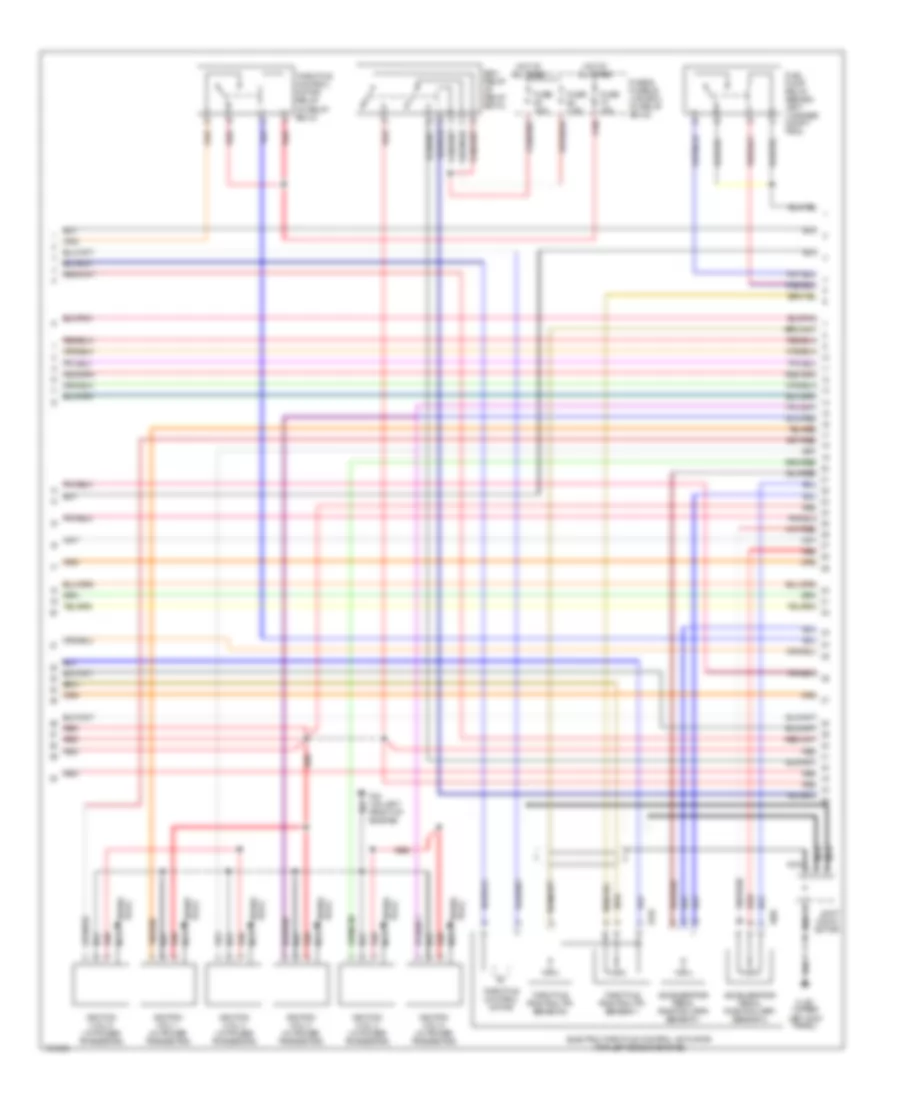
3.5L, Engine Performance Wiring Diagram (2 of 4) for Nissan Pathfinder SE 2004
 https://portal-diagnostov.com/license.html
Automotive Electricians Portal FZCO
Automotive Electricians Portal FZCO
https://portal-diagnostov.com/license.html
https://portal-diagnostov.com/license.html
Automotive Electricians Portal FZCO
Automotive Electricians Portal FZCOList of elements for 3.5L, Engine Performance Wiring Diagram (2 of 4) for Nissan Pathfinder SE 2004:
- (in relay box 2)
- Accelerator pedal position (app) sensor 1
- Accelerator pedal position (app) sensor 2
- Ecm relay (in relay box 2)
- Electric throttle control actuator (top left side of engine)
- F20 (on left front of engine)
- F205
- F210
- Fuel pump relay (behind left luggage compt trim)
- Fuse & fusible link box (in relay box 2)
- Fuse 10a
- Fuse 15a
- Fuse 7.5a
- Hot at all times
- Ignition coil 1 (w/ power transistor)
- Ignition coil 2 (w/ power transistor)
- Ignition coil 3 (w/ power transistor)
- Ignition coil 4 (w/ power transistor)
- Ignition coil 5 (w/ power transistor)
- Ignition coil 6 (w/ power transistor)
- Joint conn- ector
- M157 (upper left kick panel)
- Nca
- Nca nca
- Plug spark
- Red
- Spark plug
- Throttle control motor
- Throttle control motor relay
- Throttle position (tp) sensor 1
- Throttle position (tp) sensor 2
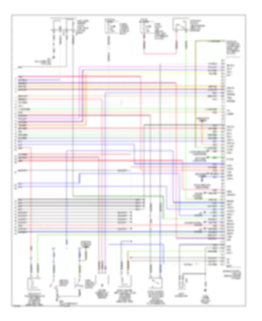
3.5L, Engine Performance Wiring Diagram (3 of 4) for Nissan Pathfinder SE 2004
 https://portal-diagnostov.com/license.html
Automotive Electricians Portal FZCO
Automotive Electricians Portal FZCO
https://portal-diagnostov.com/license.html
https://portal-diagnostov.com/license.html
Automotive Electricians Portal FZCO
Automotive Electricians Portal FZCOList of elements for 3.5L, Engine Performance Wiring Diagram (3 of 4) for Nissan Pathfinder SE 2004:
- 26u
- 37u
- Camshaft position sensor (phase) (bank 1) (right front of engine)
- Camshaft position sensor (phase) (bank 2) (left front of engine)
- Engine coolant temperature sensor (rear of engine on water outlet)
- Evap control system pressure sensor (left rear underside of vehicle, near fuel tank)
- F204
- Fuse 15a
- Fuse block (j/b) (behind dash, left of steering column)
- Heated oxygen sensor 1 (bank 1) (on right exhaust manifold)
- Heated oxygen sensor 1 (bank 2) (on left exhaust manifold)
- Heated oxygen sensor 2 (bank 1) (on right front exhaust tube, downstream of twc)
- Heated oxygen sensor 2 (bank 2) (on left front exhaust tube, downstream of twc)
- Hot in on or start
- Intake valve timing control solenoid valve (bank 1) (on left side of engine)
- Intake valve timing control solenoid valve (bank 2) (on right side of engine)
- Joint conn- ector
- Joint connector
- M158 (upper left kick panel)
- Mass airflow (maf) sensor (on air intake assembly, near air cleaner box)
- Pnk
- Red
- Sens gnd
- Sens pwr
- Tacho
- Th sens
- Transmission control module (behind dash, left of steering column)
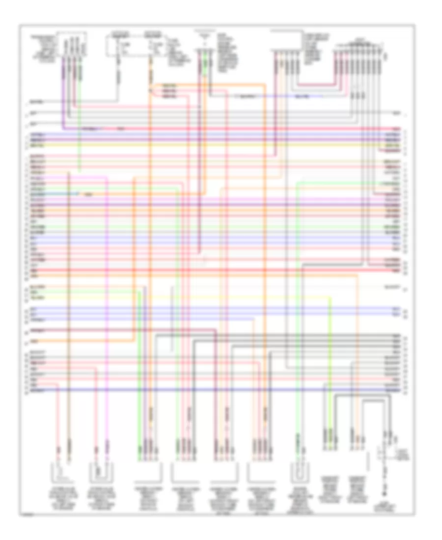
3.5L, Engine Performance Wiring Diagram (4 of 4) for Nissan Pathfinder SE 2004
 https://portal-diagnostov.com/license.html
Automotive Electricians Portal FZCO
Automotive Electricians Portal FZCO
https://portal-diagnostov.com/license.html
https://portal-diagnostov.com/license.html
Automotive Electricians Portal FZCO
Automotive Electricians Portal FZCOList of elements for 3.5L, Engine Performance Wiring Diagram (4 of 4) for Nissan Pathfinder SE 2004:
- 39u
- A/c system
- A/t
- Acrly
- Anti-theft lines system
- Aps1
- Aps2
- Arcon
- Ascdsw
- Avcc
- Avcc2
- B11 (on lower left "a" pillar)
- B13
- B55 (on lower right "a" pillar)
- Batt
- Bncsw
- Brake
- Bst sw
- Can l
- Can-h
- Cdcv
- Computer data lines system
- Cruise control system
- Cvbv
- Data link connector (lower dash panel, left of steering column)
- Defogger system
- Engine control module (behind center of dash)
- Evap canister vent control valve (left rear underside of vehicle, near fuel tank)
- F204
- Fpr
- Fuel level sensor unit & fuel pump (in fuel tank) b12
- Fuse & fusible link box (in relay box 2)
- Fuse 10a
- Fuse 7.5a
- Fuse block (j/b) (behind dash, left of steering column)
- Gnd
- Gnd 02
- Gnd a
- Gnd a2
- Gnd-m
- Headlights system
- Hlamp
- Hot at all times
- Ign 1
- Ign 2
- Ign 3
- Ign 4
- Ign 5
- Ign 6
- Ign sw
- Imline
- Joint connector
- Kline
- M/t
- M158 (upper left kick panel)
- Moyrly
- Neut
- Neutral position switch
- O2srr
- P/n
- Park/ neutral position switch
- Pdpres
- Pnk
- Power steering oil pressure sensor
- Pspres
- R/def
- Red
- Ssoff
- Starting/ charging system
- Stoplight switch (above brake pedal, on bracket)
- Swirl control valve control vacuum check switch (near brake fluid reservoir)
- Tacho
- Tps2
- Tv00
- Vacuum cut valve bypass valve (left rear underside of vehicle, near fuel tank)

 Čeština
 Dansk
Dansk Deutsch
 Ελληνικά
 English
 English
 Español
 Suomi
Suomi Français
 Français
 עברית
עברית Hrvatski
 Magyar
 Italiano
 日本語
日本語 한국어
한국어 Nederlands
 Polski
 Português
 Português
 Română
 Русский
 Slovenčina
 Slovenščina
 Svenska
 中文 (中国)
