SUPPLEMENTAL RESTRAINTS
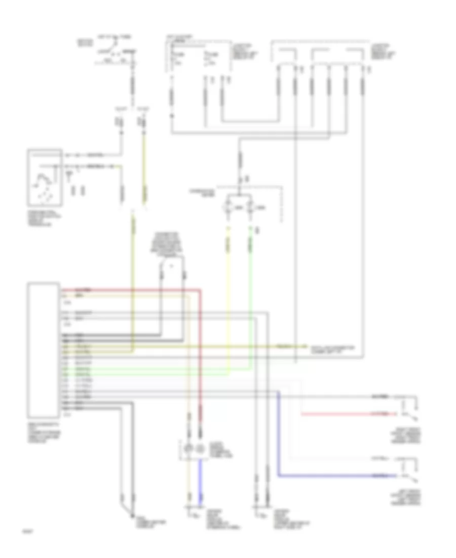
Supplemental Restraint Wiring Diagram for Mitsubishi Galant ES 1994
 https://portal-diagnostov.com/license.html
Automotive Electricians Portal FZCO
Automotive Electricians Portal FZCO
https://portal-diagnostov.com/license.html
https://portal-diagnostov.com/license.html
Automotive Electricians Portal FZCO
Automotive Electricians Portal FZCO
List of elements for Supplemental Restraint Wiring Diagram for Mitsubishi Galant ES 1994:
- 10a
- Acc
- Air bag squib module (center of steering wheel)
- Air bag squib module (upper center of right side i/p)
- B26
- C14
- C15
- C16
- C35
- C37
- C45
- C48
- Clock- spring (steering wheel hub)
- Combination meter
- Connector lock switch (shorting bar integrated in srs connector lock clip)
- D02
- D03
- Data link connector (under left i/p)
- Dohc
- Fuse
- G302 (under center console)
- Hot at all times
- Hot in start or on
- Ignition switch
- Junction block 1 (behind left side of i/p)
- Junction block 2 (behind left side of i/p)
- Left front impact sensor (left front fender apron)
- Lock
- Nca
- Park/neutral position switch (side of transaxle)
- Red
- Right front impact sensor (right front fender apron)
- Sohc
- Srs
- Srs diagnostic unit (under storage area in center console)
- Start
- W/ a/t
- W/ m/t
 Čeština
 Dansk
Dansk Deutsch
 Ελληνικά
 English
 English
 Español
 Suomi
Suomi Français
 Français
 עברית
עברית Hrvatski
 Magyar
 Italiano
 日本語
日本語 한국어
한국어 Nederlands
 Polski
 Português
 Português
 Română
 Русский
 Slovenčina
 Slovenščina
 Svenska
 中文 (中国)
 Türkçe
