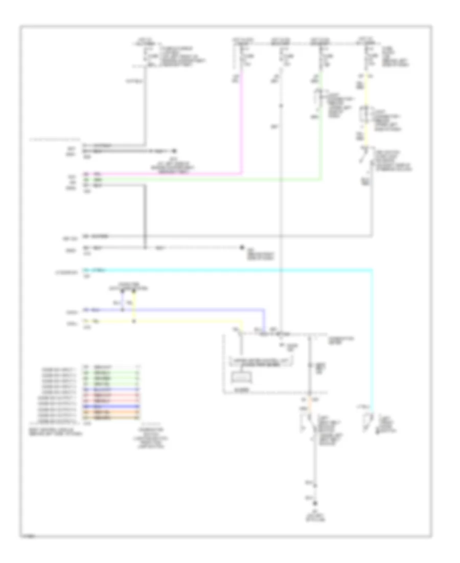
WARNING SYSTEMS
Warning Systems Wiring Diagram for Nissan Altima SL 2003
 https://portal-diagnostov.com/license.html
Automotive Electricians Portal FZCO
Automotive Electricians Portal FZCO
https://portal-diagnostov.com/license.html
https://portal-diagnostov.com/license.html
Automotive Electricians Portal FZCO
Automotive Electricians Portal FZCO
List of elements for Warning Systems Wiring Diagram for Nissan Altima SL 2003:
- 12p
- Acc
- B7 (on left "b" pillar)
- Bat
- Body control module (behind left side of dash)
- Buzzer
- Can-h
- Can-l
- Combi sw input 1
- Combi sw input 2
- Combi sw input 3
- Combi sw input 4
- Combi sw input 5
- Combi sw output 1
- Combi sw output 2
- Combi sw output 3
- Combi sw output 4
- Combi sw output 5
- Combination meter
- Combination switch (lighting switch, front fog lamp switch)
- Computer data lines system
- Door ind
- E15 (at left side of engine compartment, near battery)
- E39
- Fuse & fusible link box (on left front of engine compartment, near battery)
- Fuse 10a
- Fuse block (j/b) (behind left side of dash)
- Fuse f 50a
- Gnd1
- Gnd2
- Gnd3
- Hot at all times
- Hot in acc or on
- Hot in on or start
- Ign
- Joint connector 1 (behind upper left side of dash)
- Key sw
- Key switch & keylock solenoid (on right side of steering column)
- Left front door switch
- Left seat belt buckle switch (inside left seat belt buckle)
- Lf door sw
- M18
- M19
- M20
- M21
- M23
- M24
- M57 (behind right side of dash)
- Seat belt ind
- Unified meter control unit (w/odo/trip meter)
 Čeština
 Dansk
Dansk Deutsch
 Ελληνικά
 English
 English
 Español
 Suomi
Suomi Français
 Français
 עברית
עברית Hrvatski
 Magyar
 Italiano
 日本語
日本語 한국어
한국어 Nederlands
 Polski
 Português
 Português
 Română
 Русский
 Slovenčina
 Slovenščina
 Svenska
 中文 (中国)
 Türkçe
