SUPPLEMENTAL RESTRAINTS
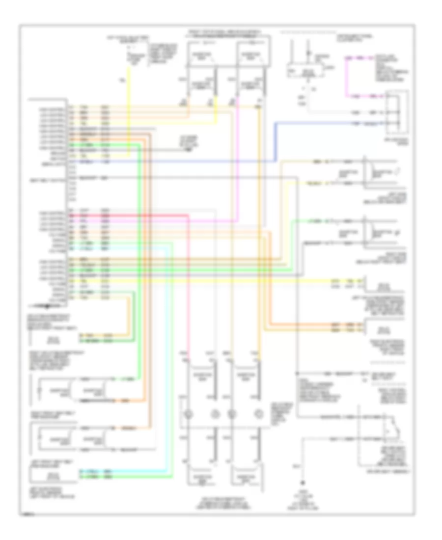
Supplemental Restraints Wiring Diagram for Chevrolet Venture 2005
 https://portal-diagnostov.com/license.html
Automotive Electricians Portal FZCO
Automotive Electricians Portal FZCO
https://portal-diagnostov.com/license.html
https://portal-diagnostov.com/license.html
Automotive Electricians Portal FZCO
Automotive Electricians Portal FZCO
List of elements for Supplemental Restraints Wiring Diagram for Chevrolet Venture 2005:
- (at base of right "b" pillar) g302
- (right top of dash, above glove box) inflatable restraint ip module
- A10
- A11
- A12
- A13
- A14
- A15
- A16
- A17
- A18
- Air bag ind
- Body control module (bcm) (below right side of dash)
- Case ground
- Data link connector (dlc) (partial) (below steering column, on knee bolster)
- Driver seat assembly
- Driver seat belt input
- Driver seat belt switch (open with driver seat belt buckled)
- G302 (w/ value van) (at base of right "b" pillar)
- Ground
- High control
- Hot in run, bulb test & start
- I/p fuse block (right side of dash, in right front door opening)
- Ign
- Ignition
- Inflatable restraint sensing & diagnostic module (sdm) (below right front seat)
- Inflatable restraint steering wheel module (center of steering wheel)
- Inflatable restraint steering wheel module coil
- Instrument panel cluster (ipc)
- Left electronic frontal sensor (left front of vehicle)
- Left front seat belt pretensioner
- Left inflatable restraint side impact sensor (inside base of left "b" pillar, near seat belt retractor)
- Left side impact module (below driver's seat)
- Logic
- Low control
- Nca
- Pnk
- Right electronic frontal sensor (right front of vehicle)
- Right front seat belt pretensioner
- Right inflatable restraint side impact sensor (inside base of right "b" pillar, near seat belt retractor)
- Right side impact module (below right front seat)
- S304 (in body harness, near breakout for inflatable restraint sensing & diagnostic module)
- Sdm/sir fuse 15a
- Seat belt switch
- Serial data
- Shorting bar
- Signal
- Solid state
- Splice pack sp205
- Tan
- Voltage
 Čeština
 Dansk
Dansk Deutsch
 Ελληνικά
 English
 English
 Español
 Suomi
Suomi Français
 Français
 עברית
עברית Hrvatski
 Magyar
 Italiano
 日本語
日本語 한국어
한국어 Nederlands
 Polski
 Português
 Português
 Română
 Русский
 Slovenčina
 Slovenščina
 Svenska
 中文 (中国)
 Türkçe
