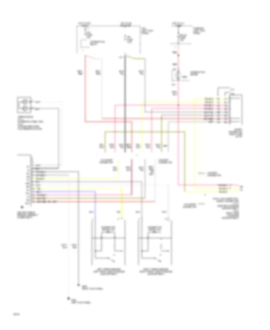
SUPPLEMENTAL RESTRAINTS
Supplemental Restraint Wiring Diagram for Toyota T100 SR5 1994
 https://portal-diagnostov.com/license.html
Automotive Electricians Portal FZCO
Automotive Electricians Portal FZCO
https://portal-diagnostov.com/license.html
https://portal-diagnostov.com/license.html
Automotive Electricians Portal FZCO
Automotive Electricians Portal FZCO
List of elements for Supplemental Restraint Wiring Diagram for Toyota T100 SR5 1994:
- +sl
- +sr
- -sl
- -sr
- 2.7l
- 3.0l
- Acc
- Airbag squib (2.7l) (steering wheel pad) (3.0l) (for driver's side) (in steering column)
- C17
- Center airbag sensor assembly (under seat)
- Cig fuse 15a
- Combination meter
- Connection detection pin
- D11
- Data link conector 1 (check connector) (2.7l) (center of engine compartment) (3.0l) (right side of engine compartment)
- Ecu-b fuse 15a
- Fuse box (left kick panel
- G200 (left kick panel)
- G203 (right kick panel)
- Hot at all times
- Hot in acc or on
- Hot in on or start
- Ig2
- Ign fuse 7.5a
- Integration relay
- J/b 1 (left kick panel)
- Left airbag sensor (left front side of engine compartment)
- Red
- Right airbag sensor (right front side of engine compartment)
- Short connector (right side of i/p)
- Srs
- W/o short connector
- W/short connector
 Čeština
 Dansk
Dansk Deutsch
 Ελληνικά
 English
 English
 Español
 Suomi
Suomi Français
 Français
 עברית
עברית Hrvatski
 Magyar
 Italiano
 日本語
日本語 한국어
한국어 Nederlands
 Polski
 Português
 Português
 Română
 Русский
 Slovenčina
 Slovenščina
 Svenska
 中文 (中国)
 Türkçe
