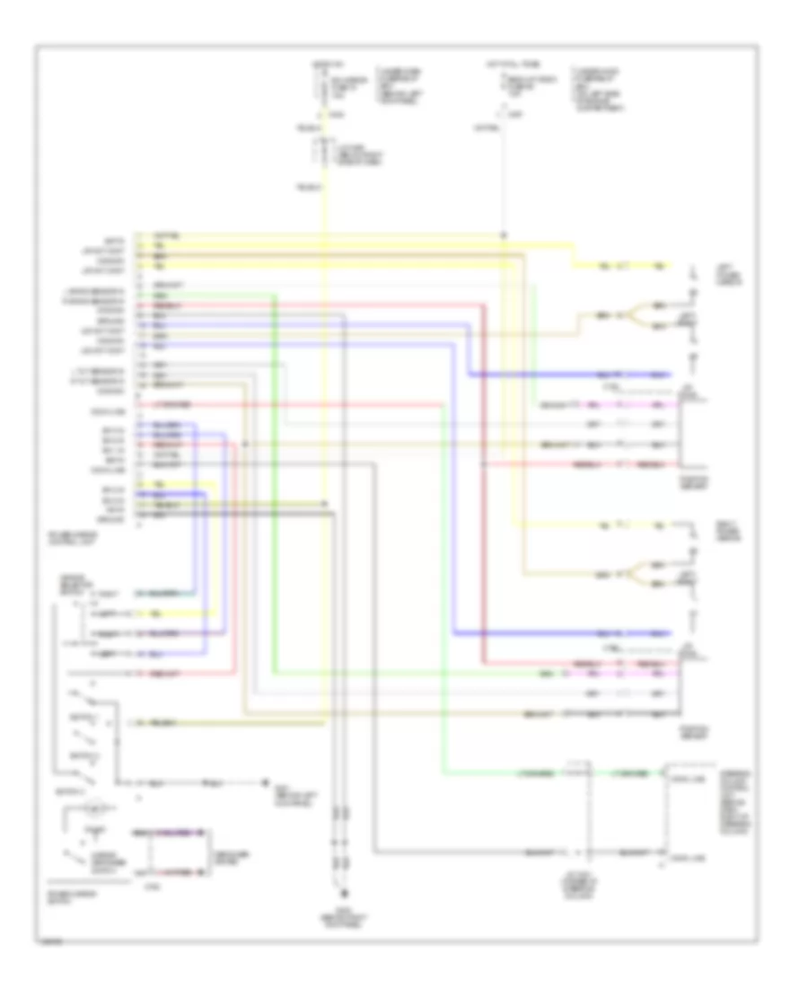
AIR CONDITIONING
Automatic A/C Wiring Diagram for Acura 3.5RL 2004
 https://portal-diagnostov.com/license.html
Automotive Electricians Portal FZCO
Automotive Electricians Portal FZCO
https://portal-diagnostov.com/license.html
https://portal-diagnostov.com/license.html
Automotive Electricians Portal FZCO
Automotive Electricians Portal FZCO
List of elements for Automatic A/C Wiring Diagram for Acura 3.5RL 2004:
- (behind
- (behind right kick panel) g402
- (on bracket)
- (on left front corner of engine compt) g301
- (on left rear of engine compt)
- 5v ref
- A/c compressor clutch
- A/c compressor clutch relay
- A/c on output
- A/c pressure switch (on front of vehicle, behind grille, on a/c line)
- A10
- A11
- A12
- A19
- A20
- Acc
- Acs
- Air mix control motor (behind right side of dash, on plenum)
- Air mix cool
- Air mix hot
- Air mix pos
- B10
- B11
- B12
- B13
- B14
- B15
- B16
- B17
- B18
- B19
- B20
- Battery
- Blower ctrl
- Blower motor (below right side of dash, on plenum)
- Blower motor high relay (behind right side of glove box)
- Blower motor relay
- C306
- C307
- C331
- C403
- C404
- Climate control unit
- Clk2
- Condenser fan motor (behind left side of radiator)
- Condenser fan relay
- D22
- Dash lights cancel mode mot pos
- Defog ctrl
- Defogger system
- Ect sens input
- Engine coolant temperature (ect) sensor (on top left front of engine, on left side of water passage)
- Evap temp input
- Evaporator temperature sensor (behind glove box, in plenum)
- Fan control unit (below front passenger's footrest)
- Fresh
- Fuse 20a
- Fuse 40a
- Fuse 7.5a
- G201 (behind right headlight)
- G302
- G402 (behind right kick panel)
- Gauge assembly
- Ground
- Hi relay ctrl
- Hot at all times
- Hot in on
- Ignition
- Illumination
- In car temp
- In-car temperature sensor
- Interior lights system
- J/c c448 (right kick panel)
- J/c c456 (below right side of dash)
- Mode control motor (behind dash, right of steering column, on plenum)
- Mode mot def
- Mode mot vent
- Navigation display unit
- Outside air temp
- Outside air temp input
- Outside air temperature sensor (behind front grille)
- Pdsw
- Pnk
- Power trans ctrl
- Power transistor (behind glove box)
- Powertrain control module (pcm) (below front passenger's footrest)
- Radiator fan control sensor (on lower right side of radiator)
- Radiator fan main relay
- Radiator fan motor (behind right side of radiator)
- Radiator fan relay
- Recirc
- Recirculation control motor (behind glove box, on plenum)
- Red
- Right kick panel) g404
- Sensor ground
- Sg2
- Sunlight sensor
- Under- hood fuse/ relay box (on left side of engine compt)
- Under-dash fuse/relay box (behind left kick panel)
- Underhood relay box a (on left front of engine compt)
- Underhood relay box c (on left front of engine compt)
ANTI-LOCK BRAKES
Anti-lock Brakes Wiring Diagram (1 of 3) for Acura 3.5RL 2004
 https://portal-diagnostov.com/license.html
Automotive Electricians Portal FZCO
Automotive Electricians Portal FZCO
https://portal-diagnostov.com/license.html
https://portal-diagnostov.com/license.html
Automotive Electricians Portal FZCO
Automotive Electricians Portal FZCOList of elements for Anti-lock Brakes Wiring Diagram (1 of 3) for Acura 3.5RL 2004:
- (in left rear corner of engine compt) pre-charge pump motor
- +b-fsr
- +b-mr
- Abs
- Bfl
- Brake pedal position switch (behind dash, top of brake pedal support)
- C301
- C303
- C305
- Can(+)
- Can(-)
- Computer data lines system
- Cruise control system
- Ebd
- Exterior lights system
- Fls(+)
- Fls(-)
- Frs(+)
- Frs(-)
- Fuse 32 vsa motor 40a
- Fuse 39 stop horn 20a
- Fuse 43 vsa 20a
- G251 (on right rear of engine compt)
- G401 (behind left kick panel)
- G403 (below center console, near data link connector)
- G601 (near base of right "b" pillar)
- G602 (at right front corner of trunk)
- Gnd
- Hot at all times
- Ig2
- Info
- J/c c421 (at base of steering column)
- J/c c464 (below right side of dash)
- J/c c487 (left side of front passenger's side floor pan)
- K-line
- M-gnd
- Nca
- Park
- Pnk
- Psm
- Pss
- Psu
- Red
- Rls(+)
- Rls(-)
- Rrs(+)
- Rrs(-)
- Sc5
- Steering angle sensor (on steering column, under combination switch)
- Stop
- Under-hood fuse/relay box (on left side of engine compt)
- Vlp(+)
- Vlp(-)
- Vsa
- Vsa hydraulic pressure sensor (at right rear of engine compt)
- Vsa modulator/ control unit (in right rear of engine compt)
- Vsa off sw
- Yaw rate/lateral acceleration sensor (behind left side of rear seat)
- Yrs ref
- Yrsa ym
- Yrsa yu
- Yrss
- Yrst
Anti-lock Brakes Wiring Diagram (2 of 3) for Acura 3.5RL 2004
 https://portal-diagnostov.com/license.html
Automotive Electricians Portal FZCO
Automotive Electricians Portal FZCO
https://portal-diagnostov.com/license.html
https://portal-diagnostov.com/license.html
Automotive Electricians Portal FZCO
Automotive Electricians Portal FZCOList of elements for Anti-lock Brakes Wiring Diagram (2 of 3) for Acura 3.5RL 2004:
- Abs ind
- Abs ind circuit
- B c752
- Brake fluid level switch (on left rear of engine compt, in brake fluid reservoir)
- Brake park input
- Brake system ind
- C307
- C321
- C322
- C331
- C405
- C502
- Daytime running lights control unit (canada)
- Drive circuit
- Driver's multiplex control unit
- Fuse 55 meter 15a
- G301 (on left front corner of engine compt)
- G401 (behind left kick panel)
- Gauge assembly
- Gauge relay
- Hot at all times
- Immobilizer control unit
- J/c c421 (at base of steering column)
- Left front wheel sensor
- Left rear wheel sensor
- Main circuit
- Parking brake switch (at left kick panel, at park brake lever)
- Pnk
- Power mirror switch
- Red
- Right front wheel sensor
- Right rear wheel sensor
- Under-dash fuse/relay box (behind left kick panel)
- Under-hood fuse/relay box (on left side of engine compt)
- Underhood relay box "c" (on left front of engine compt)
- Vsa activation ind
- Vsa ind
- Vsa ind circuit
Anti-lock Brakes Wiring Diagram (3 of 3) for Acura 3.5RL 2004
 https://portal-diagnostov.com/license.html
Automotive Electricians Portal FZCO
Automotive Electricians Portal FZCO
https://portal-diagnostov.com/license.html
https://portal-diagnostov.com/license.html
Automotive Electricians Portal FZCO
Automotive Electricians Portal FZCOList of elements for Anti-lock Brakes Wiring Diagram (3 of 3) for Acura 3.5RL 2004:
- +b-stm
- C302
- C306
- C402
- C405
- C502
- Can sld
- Can(+)
- Can(-)
- Engine controls system
- Engine controls system (throttle position sensor)
- Fuse 19 r/c mirror 7.5a
- Fuse 20 ecu 20a
- Fuse 42 tcs 15a
- G101 (top left of engine)
- G404 (behind right kick panel)
- Hot at all times
- Hot in on
- Hot in on or start
- Ig1
- Ig2
- Interior lights system
- J/c c114 (at front of engine)
- J/c c421 (at base of steering column)
- J/c c448 (above right kick panel)
- J/c c456 (below right side of dash)
- J/c c464 (below right side of dash)
- Lg1
- Lg2
- Nep
- Off
- Pnk
- Powertrain control module (pcm) (below front passenger's footrest)
- Red
- Sdla
- Sdlb
- Service check connector (below right side of dash, under glove box)
- Sg2
- Sld
- Stm fsr
- Stm gnd
- Stm(+)
- Stm(-)
- Sub- throttle motor fail-safe relay
- Tc stb
- Tc-fc
- Tcfc
- Tcstb
- Thl1
- Thl2
- Tps
- Under-dash fuse/relay box (behind left kick panel)
- Under-hood fuse/relay box (on left side of engine compt)
- Underhood relay box "c" (on left front of engine compt)
- Vcc2
- Vref
- Vsa control valve actuator (center front of engine)
- Vsa control valve angle sensor (at front of eng)
- Vsa converter unit (at right kick panel)
- Vsa switch
- Vsa switch light
ANTI-THEFT
Anti-theft Wiring Diagram for Acura 3.5RL 2004
 https://portal-diagnostov.com/license.html
Automotive Electricians Portal FZCO
Automotive Electricians Portal FZCO
https://portal-diagnostov.com/license.html
https://portal-diagnostov.com/license.html
Automotive Electricians Portal FZCO
Automotive Electricians Portal FZCOList of elements for Anti-theft Wiring Diagram for Acura 3.5RL 2004:
- (at left rear corner of trunk, near taillight) g701
- (not used)
- A-d line
- A10
- A12
- A13
- A14
- A16
- A21
- A22
- A23
- Audio unit
- Audio unit in
- B10
- B14
- B15
- B16
- B18
- B20
- B22
- B23
- Back up radio fuse 56 7.5a
- Battery
- Battery input
- C15
- C301
- C306
- C307
- C404
- C406
- C651
- D-a line
- Door d-line
- Door lock fuse 44 20a
- Door locks system (keyless entry)
- Door multiplex control unit
- Door sw in
- Door switch
- Driver's door key cylinder switch (in driver's door)
- Driver's door latch
- Driver's multiplex control unit
- Drvr door sw in
- Exterior & interior lights systems
- Front passen- ger's door key cylinder switch
- Front passen- ger's door latch
- G201 (behind right headlight)
- G251 (on right rear of engine compt)
- G402 (behind right kick panel)
- G601 (near base of right "b" pillar)
- G651 (near base of left "b" pillar)
- G701 (at left rear corner of trunk, near taillight)
- Ground
- Headlights systems
- Hlight relay ctrl
- Hood in
- Hood switch (at hood latch assembly)
- Horn relay ctrl
- Horns system
- Hot at all times
- Hot in on or start
- Ign in
- Ign key sw in
- Ignition key switch (part of steering lock)
- Instrument cluster system
- J/c c448 (right kick panel)
- Knob switch
- Left rear door latch
- Lock
- Lock input
- Lock knob switch
- Memory & instrument cluster systems
- Moonroof fuse 13 7.5a
- Navigation display unit
- Onstar control unit (behind right side of rear seat)
- Panic
- Passenger's multiplex control unit (behind right kick panel)
- Pnk
- Right rear door latch
- Security diode (behind left kick panel)
- Security horn (at right front of engine compt)
- Security horn relay
- Security ind ctrl
- Security indicator
- Stop horn fuse 39 20a
- Tlight relay ctrl
- Trnk key cyl sw in
- Trunk
- Trunk key cylinder switch (right underside of trunk lid)
- Trunk latch sw in
- Trunk latch switch (part of trunk latch)
- Under-dash fuse/relay box (behind left kick panel)
- Under-hood fuse/relay box (on left side of engine compt)
- Underhood relay box a (on left front of engine compt)
- Unlock
- Unlock input
- Wake up
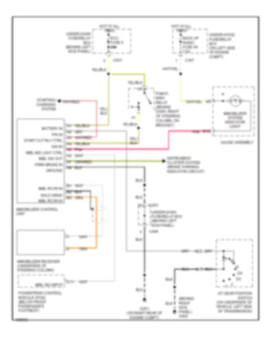
Immobilizer Wiring Diagram for Acura 3.5RL 2004
 https://portal-diagnostov.com/license.html
Automotive Electricians Portal FZCO
Automotive Electricians Portal FZCO
https://portal-diagnostov.com/license.html
https://portal-diagnostov.com/license.html
Automotive Electricians Portal FZCO
Automotive Electricians Portal FZCOList of elements for Immobilizer Wiring Diagram for Acura 3.5RL 2004:
- (behind right kick panel) g402
- A/t gear position switch (on underside of vehicle, left side of transmission)
- B19
- Back up radio fuse 56 7.5a
- Battery in
- C11
- C307
- C403
- C406
- C501
- Ecu fuse 6 20a
- G251 (on right rear of engine compt)
- Gauge assembly
- Ground
- Hot at all times
- Ign in
- Imbl ind lght ctrl
- Imbl rcvr in
- Imbl sig input
- Imbl sig out
- Immobilizer control unit
- Immobilizer receiver (underside of steering column)
- Immobilizer system indicator light
- Instrument cluster system (brake warning indicator circuit)
- P/n in
- Park brake in
- Pgm-fi main relay (behind dash, right of steering column, on bracket)
- Pnk
- Powertrain control module (pcm) (below front passenger's footrest)
- Start cut rly ctrl
- Starting/ charging system
- Under-dash fuse/relay box (behind left kick panel)
- Under-hood fuse/relay box (on left side of engine compt)
BODY CONTROL MODULES
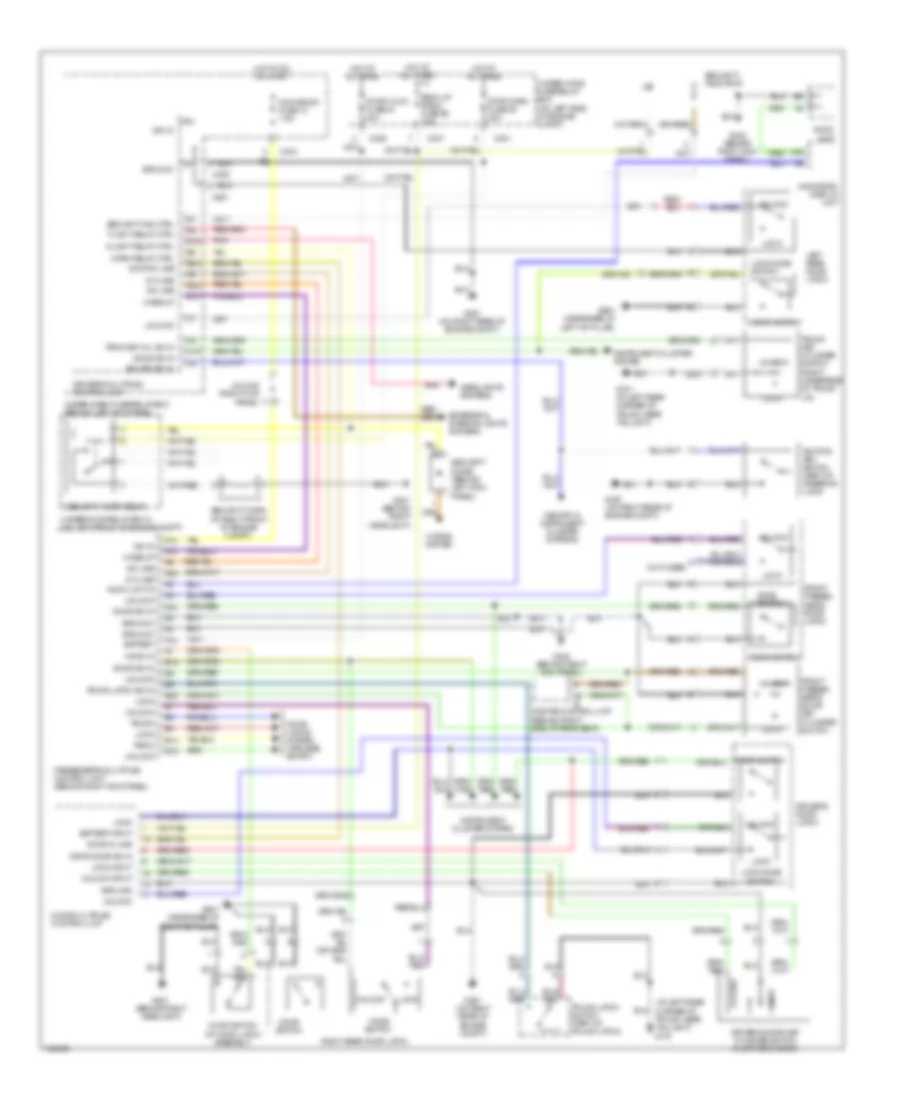
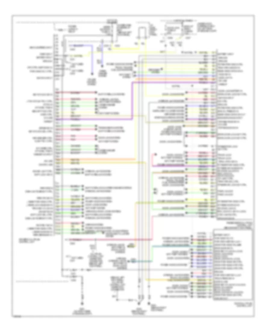
Multiplex Control Wiring Diagram for Acura 3.5RL 2004
 https://portal-diagnostov.com/license.html
Automotive Electricians Portal FZCO
Automotive Electricians Portal FZCO
https://portal-diagnostov.com/license.html
https://portal-diagnostov.com/license.html
Automotive Electricians Portal FZCO
Automotive Electricians Portal FZCOList of elements for Multiplex Control Wiring Diagram for Acura 3.5RL 2004:
- (behind left kick panel) multiplex control unit inspection connector
- (not used)
- A-d line
- A10
- A11
- A12
- A13
- A14
- A15
- A16
- A17
- A18
- A19
- A20
- A21
- A22
- A23
- A24
- A25
- A26
- Anti-theft system
- Audio unit in
- B10
- B11
- B12
- B13
- B14
- B15
- B16
- B17
- B18
- B19
- B20
- B21
- B22
- B23
- B24
- B25
- B26
- Back up radio fuse 56 7.5a
- Battery input
- Brake sw in
- C10
- C11
- C12
- C13
- C14
- C15
- C16
- C306
- C307
- C330
- C331
- C401
- C402
- C403
- C404
- C405
- C406
- C502
- Coil
- Cruise control system
- Ctsy lights ctrl
- D-a line
- Dash lghts bright ctrl
- Defogger system
- Dim ctrl
- Door d-line
- Door lock battery in
- Door lock fuse 44 20a
- Door locks & anti-theft systems
- Door locks system
- Door locks, interior lights, power windows & anti-theft systems
- Door multiplex control unit
- Dr stblt sw in
- Driver's multiplex control unit
- Drvr door sw in
- Drvr key cyl sw in (lock)
- Drvr key cyl sw in (unlock) drvr lock knob sw in (unlock) drvr lock sw in (unlock)
- Drvr lock knob sw in (lock) drvr lock sw in (lock)
- Drvr pwr wndo mtr ctrl
- Drvr pwr wndo pulser
- Drvr pwr wndo sw ctrl
- Drvr/lr dr lock act ctrl
- Eng oil pres sw in
- Engine running input
- Fpas/rr dr lock act ctrl
- Fpass/rr dr lock act ctrl
- Fr pas door sw in
- Fr pas pwr wndo ctrl
- Fr pass knob sw in
- G251 (on right rear of engine compt)
- G402 (behind right kick panel)
- G404 (behind right kick panel)
- Ground
- Hlight rly ctrl
- Hood sw in
- Horn ctrl
- Hot at all times
- Hot in on or start
- Ign key lght ctrl
- Ign key sw in
- Ignition input
- Instrument cluster system
- Int dwel time in
- Int on in
- Int wiper ctrl
- Interior lights & anti-theft systems
- Interior lights & door locks systems
- Interior lights system
- Interior lights system trunk, tailgate, fuel doors system
- Interior lights, anti-theft & door locks systems
- J/c c448 (right kick panel)
- Key intlock sol ctrl
- Key intlock sw in
- Keyless bzr ctrl
- L rear door sw in
- L rear lock knob sw in
- L rear pwr wndo ctrl
- Lt on in/tlght rly ctrl
- Main sw out
- Meter sunroof fuse 13 7.5a
- Mpx chk con in
- Mpx ctrl insp conn in
- Multiplex control unit inspection connector (behind left kick panel)
- Panic unlock
- Park brake sw in
- Park input
- Park pin sw in
- Park pos in
- Passenger's multiplex control unit (behind right kick panel)
- Pnk
- Power window relay
- Power windows system
- Pwr wnd mast sw illum -
- Pwr wnd mast sw ilum +
- Pwr wndo rly ctrl
- Pwr wndo rly in
- Rear wndo dfog on in
- Rear wndo dfog on out
- Red
- Rf door lock in
- Rf door unlock in rfd lock cyl sw in (unlock) int light ctrl
- Rfd lock cyl sw in (lock)
- Rt rear door sw in
- Rt rear dr knob sw in
- Rt rear pwr wndo ctrl
- Security ind ctrl
- Shft lock cir in
- Shft lock sol ctrl
- Shift interlock & wiper/washer systems
- Shift interlock system
- Starting/charging system
- Transmissions system
- Trnk key cyl sw in
- Trnk latch sw in
- Trnk openr sw in
- Trnk opn main sw in
- Trnk opn sol ctrl
- Trunk lock
- Trunk, tailgate & fuel doors system
- Trunk, tailgate, fuel doors system
- Under-dash fuse/relay box (behind left kick panel)
- Under-hood fuse/relay box (on left side of engine compt)
- Vehicle speed input
- Wakeup
- Warning & door locks systems
- Warning system
- Warning, interior lights, anti-theft & door locks systems
- Washer on input
- Wiper/ washer system
- Wiper/washer system
COMPUTER DATA LINES
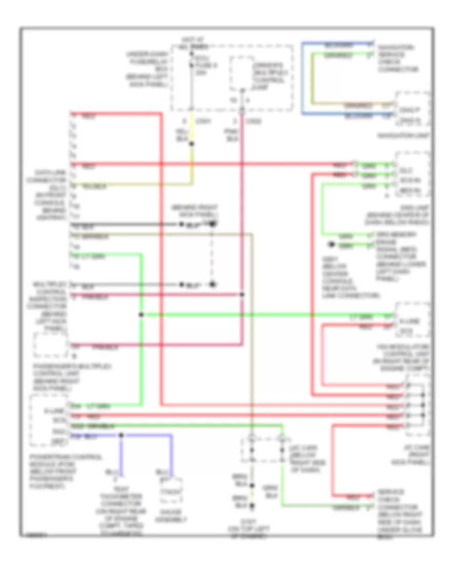
Computer Data Lines Wiring Diagram for Acura 3.5RL 2004
 https://portal-diagnostov.com/license.html
Automotive Electricians Portal FZCO
Automotive Electricians Portal FZCO
https://portal-diagnostov.com/license.html
https://portal-diagnostov.com/license.html
Automotive Electricians Portal FZCO
Automotive Electricians Portal FZCOList of elements for Computer Data Lines Wiring Diagram for Acura 3.5RL 2004:
- (behind right kick panel) g402
- (below right side of dash, under glove box)
- C5 scs
- C501
- C502
- Check connector
- Console, behind ashtray)
- D22
- Data link connector (dlc) (in front
- Diag n
- Diag p
- Dlc
- Driver's multiplex control unit
- Ecu fuse 6 20a
- Erase signal (mes) connector (behind lower left dash panel)
- G101 (on top left of engine)
- G801 (below center console, near data link connector)
- Gauge assembly
- Hot at all times
- J/c c448 (right kick panel)
- J/c c456 (below right side of dash)
- K-line
- Mes in
- Multiplex control inspection connector (behind left kick panel)
- Navigation service
- Navigation unit
- Nep
- Passenger's multiplex control unit (behind right kick panel)
- Powertrain control module (pcm) (below front passenger's footrest)
- Red
- Scs
- Scs in
- Service check connector
- Sg2
- Srs memory
- Srs unit (behind center of dash, below radio)
- Tach
- Test tachometer connector (on right rear of engine compt, taped to harness)
- Under-dash fuse/relay box (behind left kick panel)
- Vsa modulator/ control unit (in right rear of engine compt)
COOLING FAN
Cooling Fan Wiring Diagram for Acura 3.5RL 2004
 https://portal-diagnostov.com/license.html
Automotive Electricians Portal FZCO
Automotive Electricians Portal FZCO
https://portal-diagnostov.com/license.html
https://portal-diagnostov.com/license.html
Automotive Electricians Portal FZCO
Automotive Electricians Portal FZCOList of elements for Cooling Fan Wiring Diagram for Acura 3.5RL 2004:
- (behind right kick panel) g402
- (on left front corner of engine compt) g301
- (on left front of engine compt)
- (on left rear of engine compt) g302
- A/c on out
- Acs
- Air conditioning system
- C306
- C331
- C403
- Cond fan rly cont
- Condenser fan fuse 50 20a
- Condenser fan motor (behind left side of radiator)
- Condenser fan relay
- Condenser fan relay cooling fan relay fuse 3 7.5a
- Cooling fan fuse 47 20a
- Ect
- Engine coolant temperature (ect) sensor (on top left front of engine, on left side of water passage)
- Fan control unit (below front passenger's footrest)
- Ground
- Hi-lo press sw in
- Hot at all times
- Hot in on
- Ignition in
- Mid press sw in
- Pdsw
- Pnk
- Powertrain control module (below front passenger's footrest)
- Rad fan sen in
- Rad main rly cont
- Radiator fan control sensor (on lower right side of radiator)
- Radiator fan main relay
- Radiator fan motor (behind right side of radiator)
- Radiator fan relay
- Red
- Sensor ground
- Sg2
- Under-dash fuse/relay box (behind left kick panel)
- Under-hood fuse/relay box (on left side of engine compt)
- Underhood relay box "a"
- Underhood relay box "c"
CRUISE CONTROL
Cruise Control Wiring Diagram for Acura 3.5RL 2004
 https://portal-diagnostov.com/license.html
Automotive Electricians Portal FZCO
Automotive Electricians Portal FZCO
https://portal-diagnostov.com/license.html
https://portal-diagnostov.com/license.html
Automotive Electricians Portal FZCO
Automotive Electricians Portal FZCOList of elements for Cruise Control Wiring Diagram for Acura 3.5RL 2004:
- (behind left kick panel)
- (not used)
- A/t gear position ind
- A/t gear position switch (on underside of vehicle, left side of transmission)
- A10
- Actuator control
- Anti-theft system
- Brake pedal position switch (behind dash, top of brake pedal support)
- Brake sw input
- C301
- C307
- C331
- C402
- C403
- C404
- C502
- C651
- Cable reel
- Cancel switch
- Cruise control actuator (on left front corner of engine compt)
- Cruise control circuit
- Cruise control indicator light
- Cruise control main switch
- Cruise control main switch light
- Cruise control set/ resume/ cancel switch
- Cruise control unit (behind dash, right of steering column)
- Cruise ctrl input
- Cruise ctrl main sw input
- Cruise ctrl sig output
- Defogger system
- Disengage input
- Drive circuit
- Driver's multiplex control unit
- Ecu fuse 20 20a
- Engine controls system
- G251 (on right rear of engine compt)
- G301 (on left front corner of engine compt)
- G401 (behind left kick panel)
- G402 (behind right kick panel)
- Gauge assembly
- Gauge relay
- Ground
- Horn
- Hot at all times
- Hot in on or start
- Ignition input
- Indicator light control
- Interior lights system
- J/c c114 (at right front of engine)
- J/c c421 (at base of steering column)
- J/c c448 (right kick panel)
- J/c c456 (below right side of dash)
- Main circuit
- Meter fuse 55 15a
- Meter, sun roof fuse 13 7.5a
- Navigation unit
- Nca
- Off
- On indicator light
- Pnk
- Powertrain control module (pcm) (below front passenger's footrest)
- Red
- Relay
- Resume/ accel switch
- Resume/accel sw input
- Safety solenoid
- Sensor ground
- Set/ decel switch
- Set/decel sw input
- Steering column control unit (behind dash, right of steering column)
- Steering wheel
- Stop horn fuse 39 20a
- To horn switches
- Under-dash fuse/relay box
- Under-dash fuse/relay box (behind left kick panel)
- Under-hood fuse/relay box (on left side of engine compt)
- Underhood relay box "c" (on left front of engine compt)
- Vacuum solenoid
- Vehicle speed input
- Vehicle speed output
- Vehicle speed sensor (vss) (on lower right front of engine)
- Vent solenoid
- Vss input
- W/ navigation
- W/o navigation
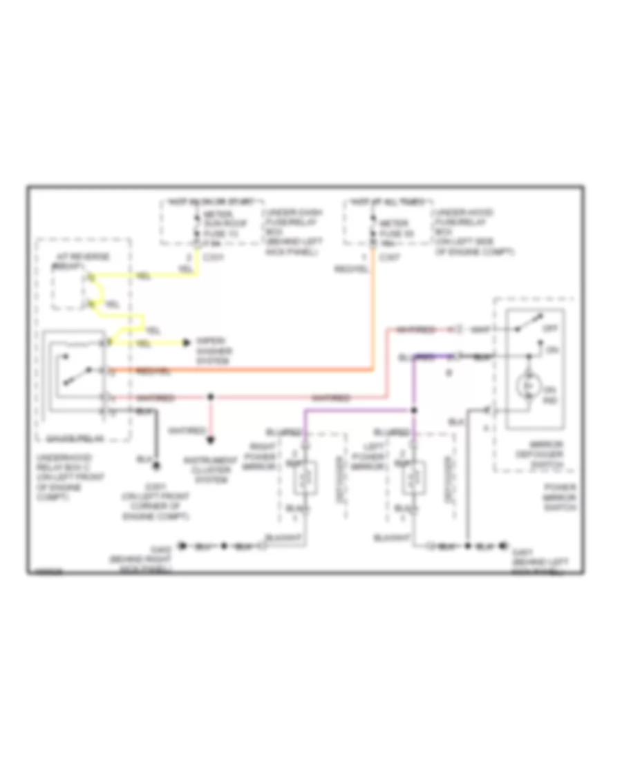
DEFOGGERS
Heated Mirrors Wiring Diagram for Acura 3.5RL 2004
 https://portal-diagnostov.com/license.html
Automotive Electricians Portal FZCO
Automotive Electricians Portal FZCO
https://portal-diagnostov.com/license.html
https://portal-diagnostov.com/license.html
Automotive Electricians Portal FZCO
Automotive Electricians Portal FZCOList of elements for Heated Mirrors Wiring Diagram for Acura 3.5RL 2004:
- A/t reverse
- C307
- C331
- Defogger
- G301 (on left front corner of engine compt)
- G401 (behind left kick panel)
- G402 (behind right kick panel)
- Gauge relay
- Hot at all times
- Hot in on or start
- Instrument cluster system
- Left power mirror
- Meter fuse 55 15a
- Meter, sun roof fuse 13 7.5a
- Mirror defogger switch
- Off
- On ind
- Power mirror switch
- Relay
- Right power mirror
- Under-dash fuse/relay box (behind left kick panel)
- Under-hood fuse/relay box (on left side of engine compt)
- Underhood relay box c (on left front of engine compt)
- Wiper/ washer system
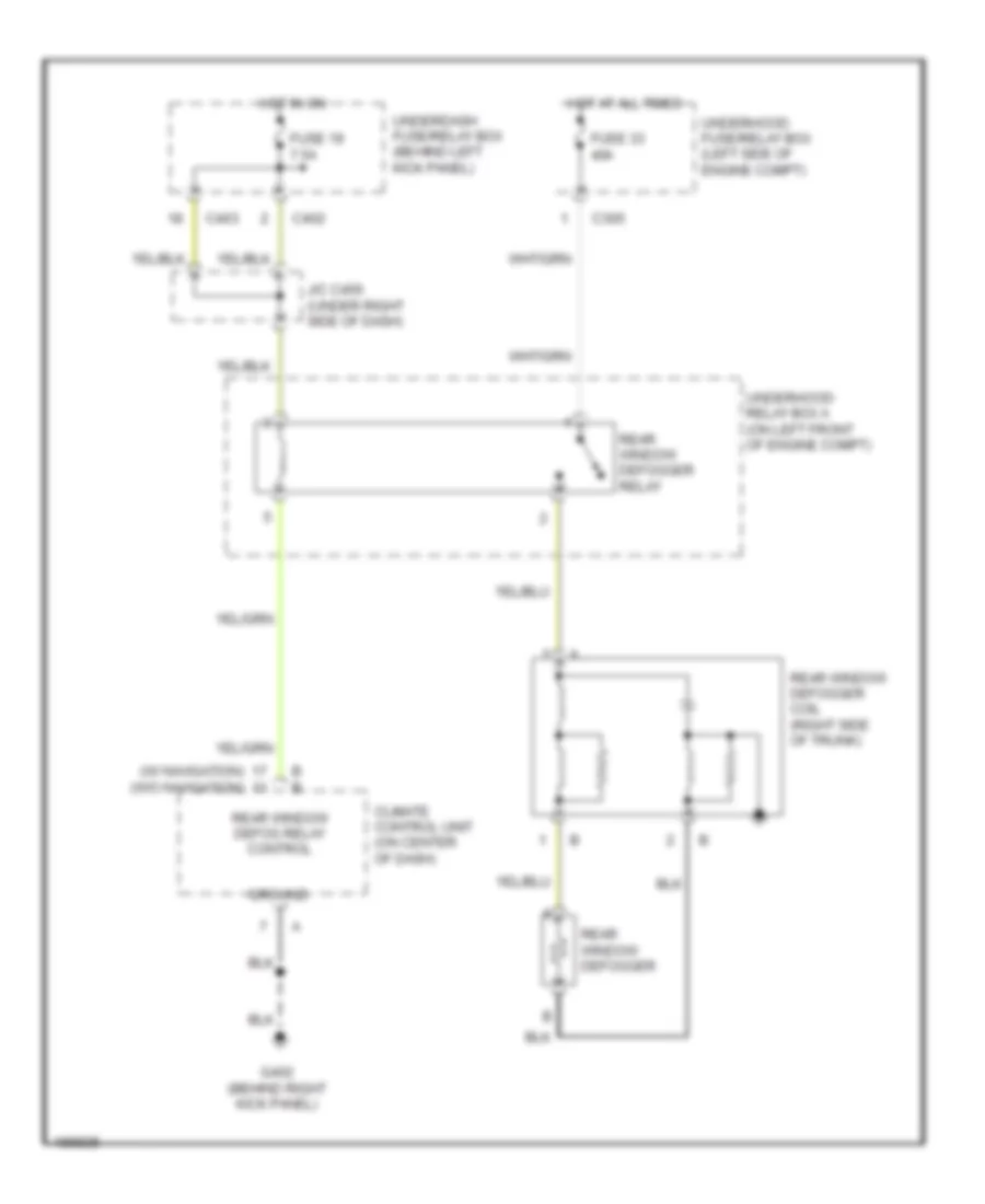
Rear Defogger Wiring Diagram for Acura 3.5RL 2004
 https://portal-diagnostov.com/license.html
Automotive Electricians Portal FZCO
Automotive Electricians Portal FZCO
https://portal-diagnostov.com/license.html
https://portal-diagnostov.com/license.html
Automotive Electricians Portal FZCO
Automotive Electricians Portal FZCOList of elements for Rear Defogger Wiring Diagram for Acura 3.5RL 2004:
- (w/ navigation) (w/o navigation)
- B b
- C305
- C402
- C403
- Climate control unit (on center of dash)
- Fuse 19 7.5a
- Fuse 33 40a
- G402 (behind right kick panel)
- Ground
- Hot at all times
- Hot in on
- J/c c456 (under right side of dash)
- Rear window defog relay control
- Rear window defogger
- Rear window defogger coil (right side of trunk)
- Rear window defogger relay
- Underdash fuse/relay box (behind left kick panel)
- Underhood fuse/relay box (left side of engine compt)
- Underhood relay box a (on left front of engine compt)
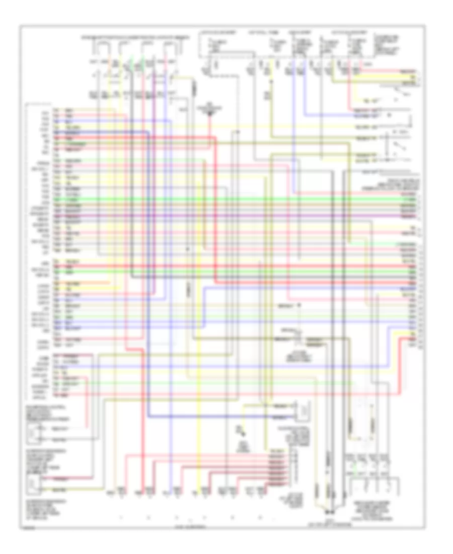
ENGINE PERFORMANCE
3.5L
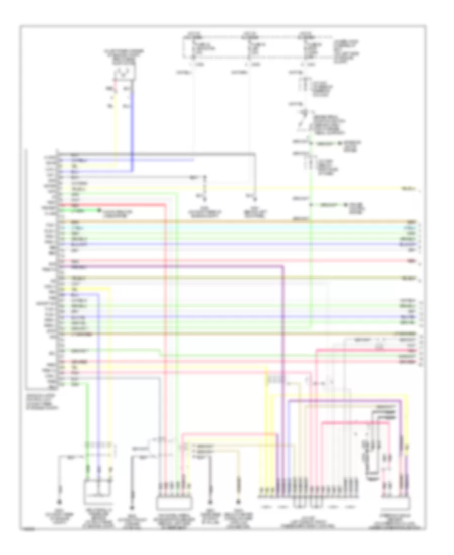
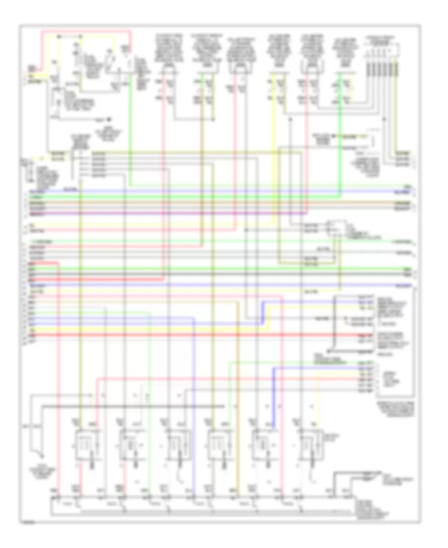
3.5L, Engine Performance Wiring Diagram (1 of 4) for Acura 3.5RL 2004
 https://portal-diagnostov.com/license.html
Automotive Electricians Portal FZCO
Automotive Electricians Portal FZCO
https://portal-diagnostov.com/license.html
https://portal-diagnostov.com/license.html
Automotive Electricians Portal FZCO
Automotive Electricians Portal FZCOList of elements for 3.5L, Engine Performance Wiring Diagram (1 of 4) for Acura 3.5RL 2004:
- 2wbs
- A10
- A11
- A12
- A13
- A14
- A15
- A16
- A17
- A18
- A19
- A20
- A21
- A22
- A23
- A24
- A25
- A26
- Acc
- Air conditioning system
- Anti- theft system
- B10
- B11
- B12
- B13
- B14
- B15
- B16
- C404
- C405
- C406
- C501
- C651
- Ckp 1
- Ckp 2
- Ckp1m
- Ckp1p
- Ckp2m
- Ckp2p
- Crankshaft position/cylinder position (ckp/cyp) sensor
- Cyp 1
- Cyp 2
- Cyp1p
- Cyp2p
- Evaporative emission (evap) by-pass solenoid valve (under left rear of vehicle)
- Evaporative emission (evap) control canister vent shut valve (under left rear of vehicle)
- Flr1
- Fprcs
- Fuel injectors
- Fuse 14 starter signal 7.5a
- Fuse 20 ecu 20a
- Fuse 22 fuel pump 20a
- Fuse 25 ig coil 30a
- Fuse 6 ecu 20a
- G101 (on top left of engine)
- Hot at all times
- Hot in on or start
- Hot in start
- Iabcs1
- Iabcs2
- Iacv
- Idle air control (iac) valve (on left side of throttle body base)
- Ign coil 1
- Ign coil 2
- Ign coil 3
- Ign coil 4
- Ign coil 5
- Ign coil 6
- Igp1
- Igp2
- Inj1
- Inj2
- Inj3
- Inj4
- Inj5
- Inj6
- J/c c146 (at left side of engine compt)
- J/c c456 (below right side of dash)
- Lg1
- Lg2
- Lpo2shtc
- Mcs
- Mfpls l
- Mfpls r
- Mil
- Pcs
- Pg1
- Pg2
- Pgm-fi main relay (behind dash, right of steering column, on bracket)
- Phrst l
- Phrst r
- Pnk
- Powertrain control module (pcm) (below front passenger's footrest)
- Psp sw
- Red
- Rpo2shtc
- Secondary heater oxygen sensor (secondary ho2s) (on side of catalytic converter)
- Sho2s
- So2sgnd
- So2shtc
- Under-dash fuse/ relay box (behind left kick panel)
- Vss
- Vsv
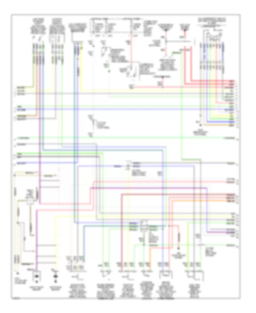
3.5L, Engine Performance Wiring Diagram (2 of 4) for Acura 3.5RL 2004
 https://portal-diagnostov.com/license.html
Automotive Electricians Portal FZCO
Automotive Electricians Portal FZCO
https://portal-diagnostov.com/license.html
https://portal-diagnostov.com/license.html
Automotive Electricians Portal FZCO
Automotive Electricians Portal FZCOList of elements for 3.5L, Engine Performance Wiring Diagram (2 of 4) for Acura 3.5RL 2004:
- (at center rear of engine) j/c c106
- (at right front of engine) j/c c114
- (on center of firewall) engine mount control solenoid valve
- (on center of firewall) intake air bypass (iab) high control solenoid valve
- (on center of firewall) intake air bypass (iab) low control solenoid valve
- (on left front of engine)
- (on right side of firewall, in control box) exhaust gas recirculation (egr) control solenoid valve
- (on right side of firewall, in control box) fuel pressure regulator control solenoid valve
- A6 red
- Anti-lock brakes system
- B4 red
- C302
- Evaporative emission (evap) purge control solenoid valve
- Front misfire pulse output
- Front peak hold reset output
- Fuel pump (on underside of vehicle, top of fuel tank)
- Fuel pump relay (behind left side of rear seat)
- Fuel pump resistor (on left side of trunk)
- G102 (on right side of engine compt)
- G151 (at lower front of engine)
- G202 (on right side of engine compt)
- G652 (at left front corner of trunk)
- Ground
- Ground rear peak hold reset output rear misfire pulse output
- Ignition
- Ignition coils
- Ignition control module (icm) (on right side of engine compt)
- J/c c421 (at base of steering column)
- Noise reduction condenser (right side of engine compt)
- Pnk
- Red
- Spark plug voltage detection module (on right rear of engine compt)
- Spark plug voltage input
- Under-hood fuse/relay box (on left side of engine compt)
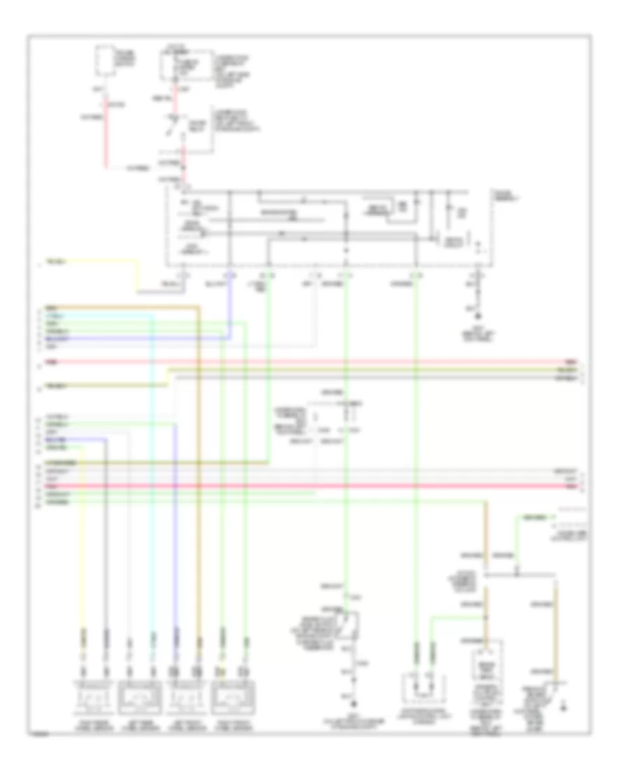
3.5L, Engine Performance Wiring Diagram (3 of 4) for Acura 3.5RL 2004
 https://portal-diagnostov.com/license.html
Automotive Electricians Portal FZCO
Automotive Electricians Portal FZCO
https://portal-diagnostov.com/license.html
https://portal-diagnostov.com/license.html
Automotive Electricians Portal FZCO
Automotive Electricians Portal FZCOList of elements for 3.5L, Engine Performance Wiring Diagram (3 of 4) for Acura 3.5RL 2004:
- (left rear of engine compt) left primary heated oxygen sensor (left primary ho2s)
- (on lower right front of engine) vehicle speed sensor (vss)
- (on right exhaust manifold) right primary heated oxygen sensor (right primary ho2s)
- (on underside of vehicle, left side of transmission) a/t gear position switch
- (right kick panel) j/c c448
- Air conditioning system
- Anti-lock brakes system
- Brake pedal position switch (behind dash, top of brake pedal support)
- C301
- C307
- Engine coolant temperature (ect) sensor (on top left front of engine, on left side of water passage)
- Exhaust gas recirculation (egr) valve position sensor (on top right rear of engine)
- Fuel tank pressure sensor (under left rear of vehicle)
- Fuse 39 stop horn 20a
- Fuse 55 meter 15a
- Fuse 56 back up radio 7.5a
- G101 (at top left of engine)
- G402 (behind right kick panel)
- Gauge relay
- Hot at all times
- Intake air temperature (iat) sensor (on center rear of engine, in intake manifold)
- J/c c114 (at right front of engine)
- J/c c448 (right kick panel)
- J/c c456 (below right side of dash)
- J/c c464 (below right side of dash)
- Left knock sensor
- Mirrors system
- P r
- Power steering pressure (psp) switch (on lower right front of engine compt, on power steering line)
- Red
- Right knock sensor
- Service check connector (below right side of dash, under glove box)
- Throttle position (tp) sensor (on top of engine, on throttle body)
- Under-hood fuse/relay box (on left side of engine compt)
- Underhood relay box "c" (on left front of engine compt)
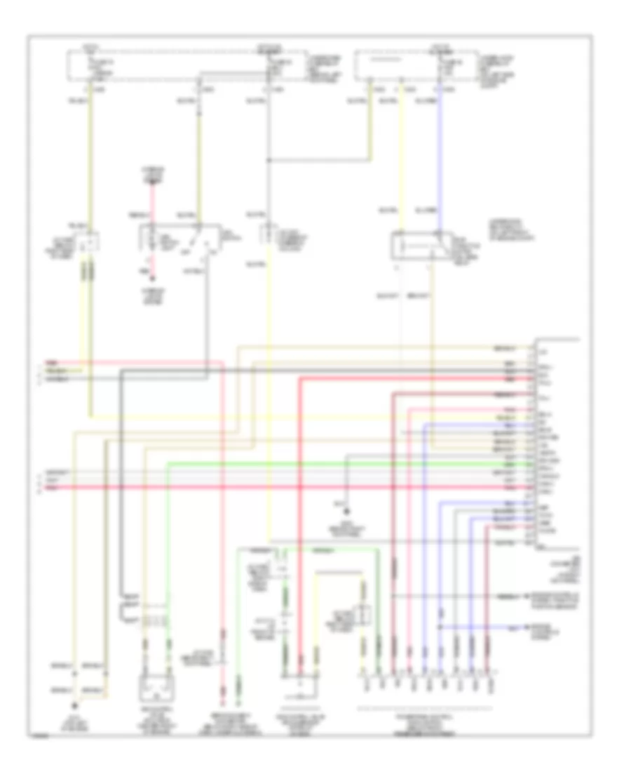
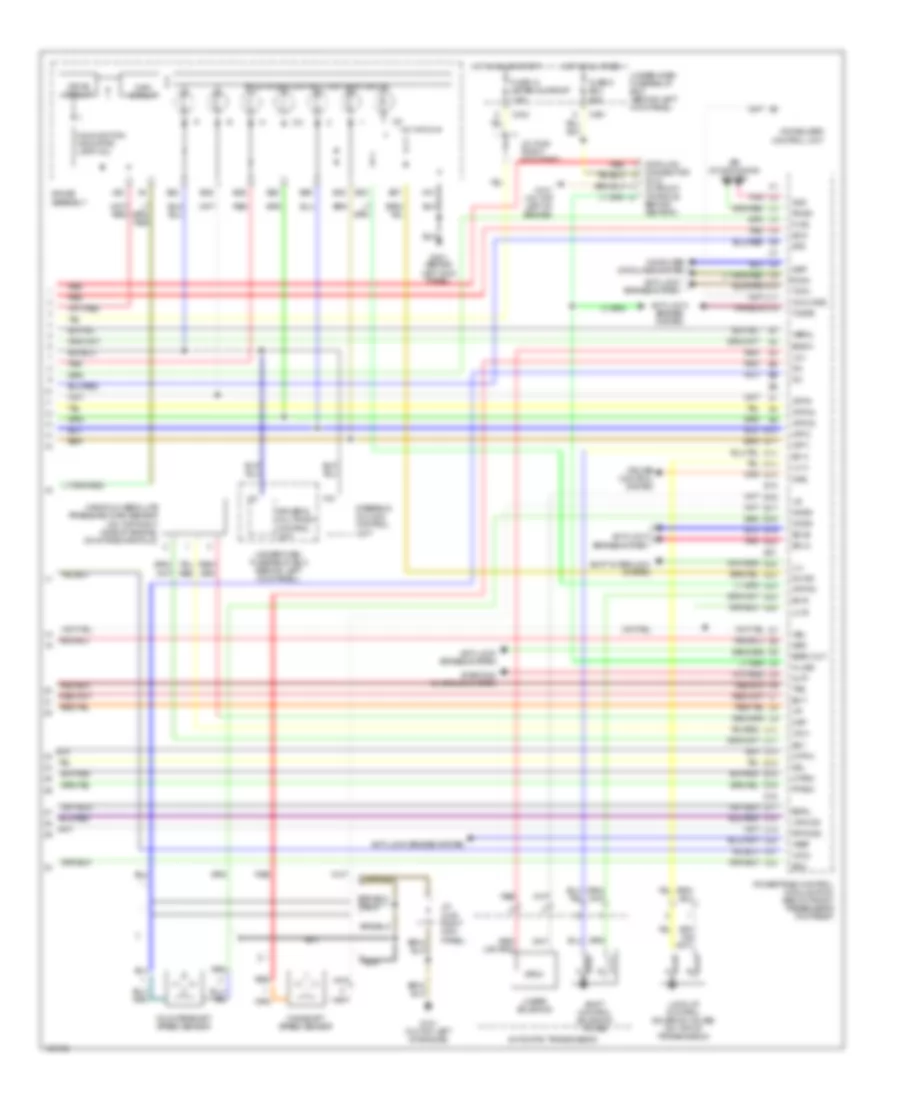
3.5L, Engine Performance Wiring Diagram (4 of 4) for Acura 3.5RL 2004
 https://portal-diagnostov.com/license.html
Automotive Electricians Portal FZCO
Automotive Electricians Portal FZCO
https://portal-diagnostov.com/license.html
https://portal-diagnostov.com/license.html
Automotive Electricians Portal FZCO
Automotive Electricians Portal FZCOList of elements for 3.5L, Engine Performance Wiring Diagram (4 of 4) for Acura 3.5RL 2004:
- A/t & cruise control lights-on circuit
- A10
- A22
- Acs
- Air conditioning system
- Altf
- Anti-lock brakes system
- Atp 1
- Atp 2
- Atp d3
- Atp d4
- Atp pn
- Atp r
- Automatic transmission
- B23
- B24
- B25
- B26
- B27
- B28
- B29
- B30
- Baro out
- Bksw
- C2 pnk
- C404
- C5 red
- C501
- Computer data lines system
- Countershaft speed sensor
- Crs
- Cruise control system
- Cyp1m
- Cyp2m
- D16
- D4 ind
- Data link connector (dlc) (in front console, behind ashtray)
- Drive circuit
- Driver's multiplex control unit
- E15
- E21
- Ect
- Egrl
- Flr2
- Fuse 13 meter sunroof 7.5a
- Fuse 6 ecu 20a
- G101 (on top left of engine)
- G401 (behind left kick panel)
- Gauge assembly
- Hot at all times
- Hot in on or start
- Iat
- Ilu
- Immobilizer control unit
- Imo code
- J/c c448 (right kick panel)
- J/c c448 right kick panel)
- K-line
- Ksl
- Ksr
- Lc a
- Lc b
- Linear solenoid
- Lock-up control solenoid valves (on top of transmission)
- Lpho2s
- Ls +
- Ls-
- Main circuit
- Mainshaft speed sensor
- Malfunction indicator lamp (mil)
- Manifold absolute pressure (map) sensor (on top right side of engine, on intake manifold)
- Map
- Ncsg
- Nep
- Nmsg
- Pdsw
- Pnk e20
- Powertrain control module (pcm) (below front passenger's footrest)
- Ptank
- Red
- Red (or pnk)
- Rpho2s
- Scs
- Sdla
- Sdlb
- Sg1
- Sg2
- Sh a
- Sh b
- Shift control solenoid valves
- Shift interlock system
- Starting/ charging system
- Steering column control unit
- Sts
- Tcfc
- Tcinh
- Tcstb
- Tps
- Under-dash fuse/relay box (behind left kick panel)
- Vbsol
- Vbu
- Vcc1
- Vcc2
- Vref
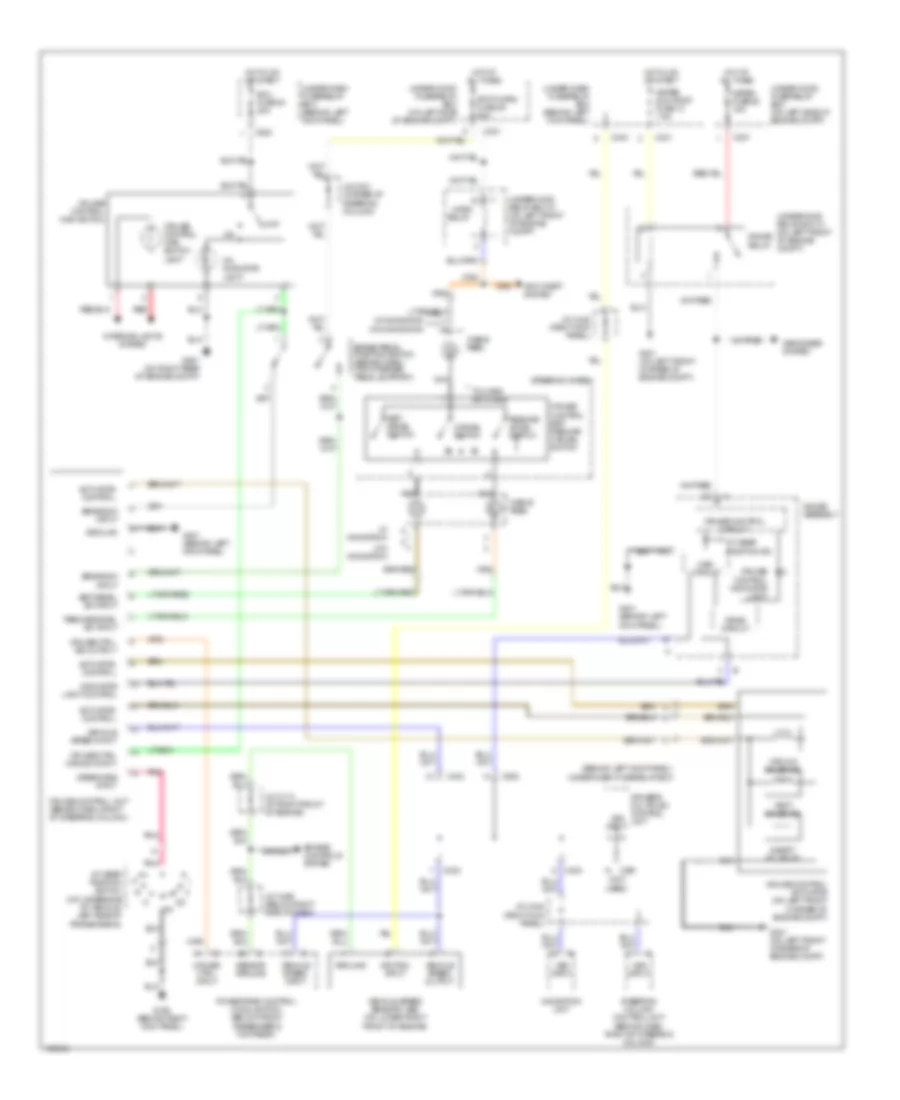
EXTERIOR LIGHTS
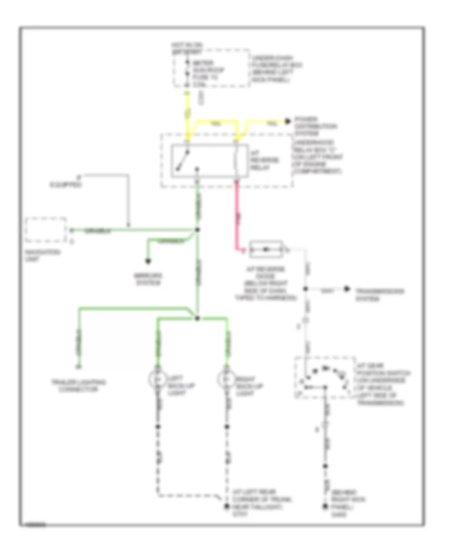
Back-up Lamps Wiring Diagram for Acura 3.5RL 2004
 https://portal-diagnostov.com/license.html
Automotive Electricians Portal FZCO
Automotive Electricians Portal FZCO
https://portal-diagnostov.com/license.html
https://portal-diagnostov.com/license.html
Automotive Electricians Portal FZCO
Automotive Electricians Portal FZCOList of elements for Back-up Lamps Wiring Diagram for Acura 3.5RL 2004:
- (at left rear corner of trunk, near taillight) g701
- (behind right kick panel) g402
- A/t gear position switch (on underside of vehicle, left side of transmission)
- A/t reverse diode (below right side of dash, taped to harness)
- A/t reverse relay
- C331
- Hot in on or start
- If equipped
- Left back-up light
- Meter sun roof fuse 13 7.5a
- Mirrors system
- Navigation unit
- Pnk
- Power distribution system
- Right back-up light
- Trailer lighting connector
- Transmissions system
- Under-dash fuse/relay box (behind left kick panel)
- Underhood relay box "c" (on left front of engine compartment)
Exterior Lamps Wiring Diagram (1 of 2) for Acura 3.5RL 2004
 https://portal-diagnostov.com/license.html
Automotive Electricians Portal FZCO
Automotive Electricians Portal FZCO
https://portal-diagnostov.com/license.html
https://portal-diagnostov.com/license.html
Automotive Electricians Portal FZCO
Automotive Electricians Portal FZCOList of elements for Exterior Lamps Wiring Diagram (1 of 2) for Acura 3.5RL 2004:
- (canada)
- (diagram 2 of 2) to underdash fuse/relay box
- (usa)
- Anti-lock brakes, cruise control, transmissions, wiper washer system
- Anti-theft system
- Auto
- Automatic lighting control unit (usa) (behind left side of rear seat)
- Back-up lamps circuit
- Brake light input
- Brake pedal position switch (behind dash, top of brake pedal support)
- C301
- C353
- C403
- C405
- C651
- Combination light switch
- G201 (behind right headlight)
- G301 (on left front corner of engine compt)
- G401 (behind left kick panel)
- G701 (at left rear corner of trunk, near taillight)
- Gauge assembly
- Head
- Head- light switch
- High mount brake light
- Hot at all times
- Hot in on or start
- Interior lights system
- J/c c421 (at base of steering column)
- J/c c456 (below right side of dash)
- Left brake lights/ taillights
- Left brake- light failure sensor (at left rear corner of trunk)
- Left front side marker light
- Left front turn signal/ parking light
- Left license light
- Meter sun roof fuse 13 7.5a
- Off
- Onstar control unit (usa) (behind right side of rear seat)
- Park
- Right brake lights/ taillights
- Right brake- light failure sensor (at right rear corner of trunk)
- Right front side marker light
- Right front turn signal/ parking light
- Right license light
- Safety indicator
- Small light fuse 1 15a
- Stop horn fuse 39 20a
- Taillight relay
- To underdash fuse/relay box (diagram 2 of 2)
- Trailer lighting connector
- Under-dash fuse/relay box (behind left kick panel)
- Under-hood fuse/relay box (on left side of engine compt)
- Underhood relay box "c" (on left front of engine compartment)
Exterior Lamps Wiring Diagram (2 of 2) for Acura 3.5RL 2004
 https://portal-diagnostov.com/license.html
Automotive Electricians Portal FZCO
Automotive Electricians Portal FZCO
https://portal-diagnostov.com/license.html
https://portal-diagnostov.com/license.html
Automotive Electricians Portal FZCO
Automotive Electricians Portal FZCOList of elements for Exterior Lamps Wiring Diagram (2 of 2) for Acura 3.5RL 2004:
- (not used)
- Battery input
- C301
- C331
- C403
- C405
- C406
- C502
- C651
- Combination light switch
- Ecu fuse 20 20a
- Flasher
- From left front turn signal/ parking light (diagram 1 of 2)
- From right front turn signal/ parking light (diagram 1 of 2)
- From trailer lighting connector (diagram 1 of 2)
- G251 (on right rear of engine compt)
- G401 (behind left kick panel)
- G701 (at left rear corner of trunk, near taillight)
- Gauge assembly
- Ground
- Hazard fuse 40 10a
- Hazard warning lights diode 1 (behind instrument cluster)
- Hazard warning lights diode 2 (behind instrument cluster)
- Hazard warning switch (w/ navigation)
- Hazard warning switch light
- Hot at all times
- Hot in on or start
- Interior lights system
- J/c c421 (at base of steering column)
- Left control
- Left input/ control
- Left rear turn signal light
- Left turn signal indicator light
- Off
- Red
- Right control
- Right input/ control
- Right rear turn signal light
- Right turn signal indicator light
- Turn left
- Turn right
- Turn signal light diode (underside of steering column)
- Turn signal switch (w/ navigation)
- Turn signal/ hazard relay (w/ navigation)
- Under-dash fuse/relay box (behind left kick panel)
- Under-hood fuse/relay box (on left side of engine compartment)
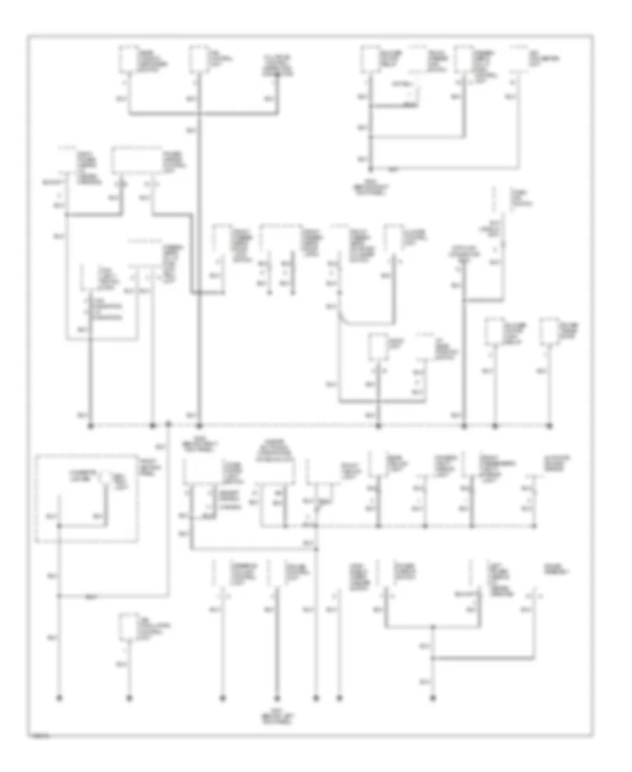
GROUND DISTRIBUTION
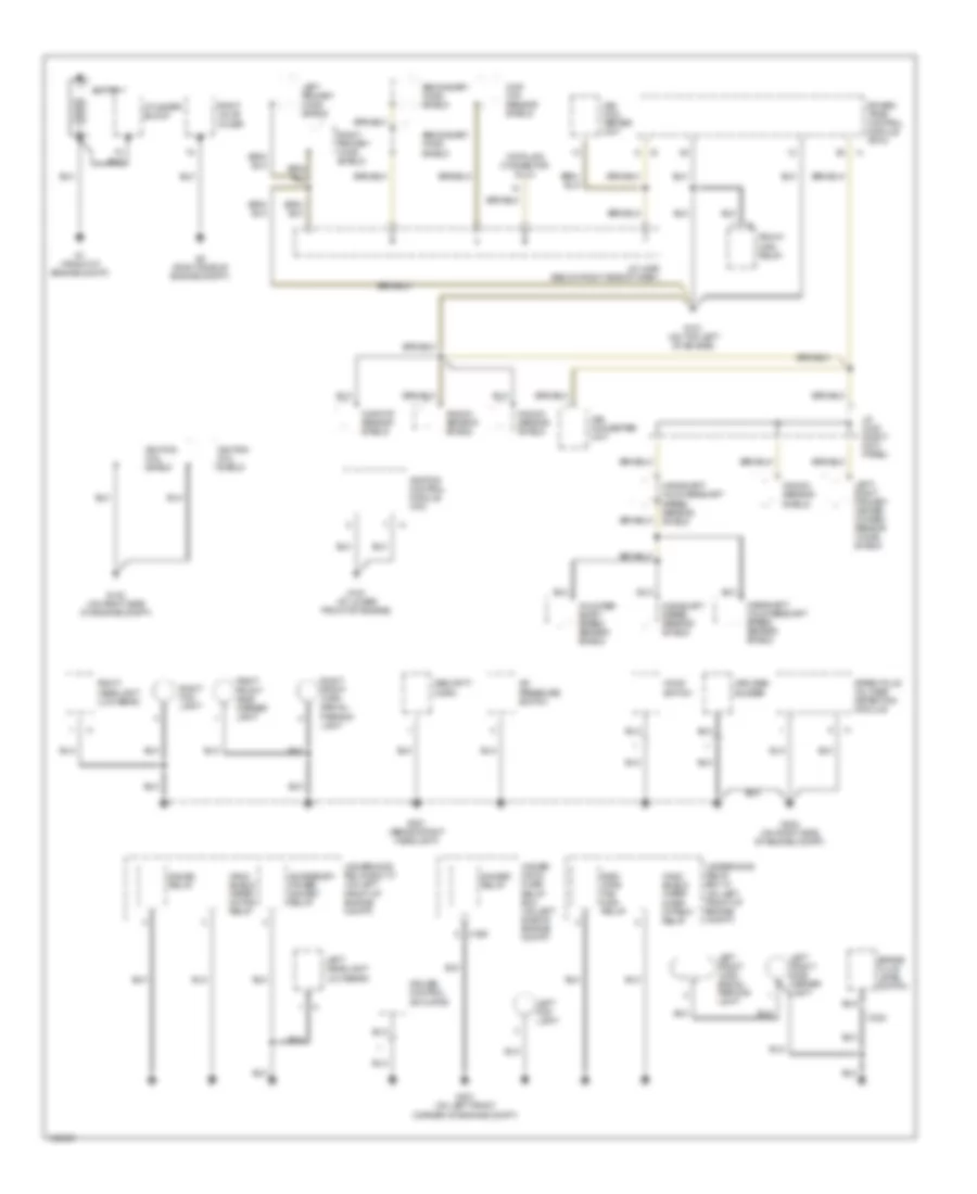
Ground Distribution Wiring Diagram (1 of 4) for Acura 3.5RL 2004
 https://portal-diagnostov.com/license.html
Automotive Electricians Portal FZCO
Automotive Electricians Portal FZCO
https://portal-diagnostov.com/license.html
https://portal-diagnostov.com/license.html
Automotive Electricians Portal FZCO
Automotive Electricians Portal FZCOList of elements for Ground Distribution Wiring Diagram (1 of 4) for Acura 3.5RL 2004:
- A/c pressure switch
- Accessory power socket relay
- Battery
- Brake fluid level switch
- C305
- C322
- Ckp/ cyp sensor shield
- Ckp/cyp sensor shield
- Counter- shaft speed sensor shield
- Cruise control actuator
- Cylinder block
- Data link connector (dlc)
- Dimmer relay
- G1 (front of engine compt)
- G101 (on top left of engine)
- G102 (on right side of engine compt)
- G151 (at lower front of engine)
- G2 (right side of engine compt)
- G201 (behind right headlight)
- G202 (on right side of engine compt)
- G301 (on left front corner of engine compt)
- Gauge relay
- Hood switch
- Ignition coil shield
- Ignition control module (icm)
- J/c c448 (right kick panel)
- J/c c456 (below right side of dash)
- Keyless buzzer
- Knock sensor shield
- Left fog light
- Left front side marker light
- Left front turn signal/ parking light
- Left headlight (low beam)
- Left primary ho2s shield
- Left/ right primary heated oxygen sensor (ho2s) shield
- Mainshaft speed sensor shield
- Mainshaft/ countershaft speed sensor shield
- Pgm-fi main relay
- Power- train control module (pcm)
- Radi- ator fan main relay
- Right fog light
- Right front side marker light
- Right front turn signal/ parking light
- Right headlight (low beam)
- Right primary ho2s shield
- Right valve cover
- Secondary ho2s shield
- Security horn
- Spark plug voltage detection module
- Under- hood fuse/ relay box (on left side of engine compt)
- Underhood relay box "a" (on left front of engine compt)
- Underhood relay box "c" (on left front of engine compt)
- Vsa con- verter unit
- Vsa converter unit
- Wind- shield wiper inter- mittent relay
- Wind- shield wiper motor relay
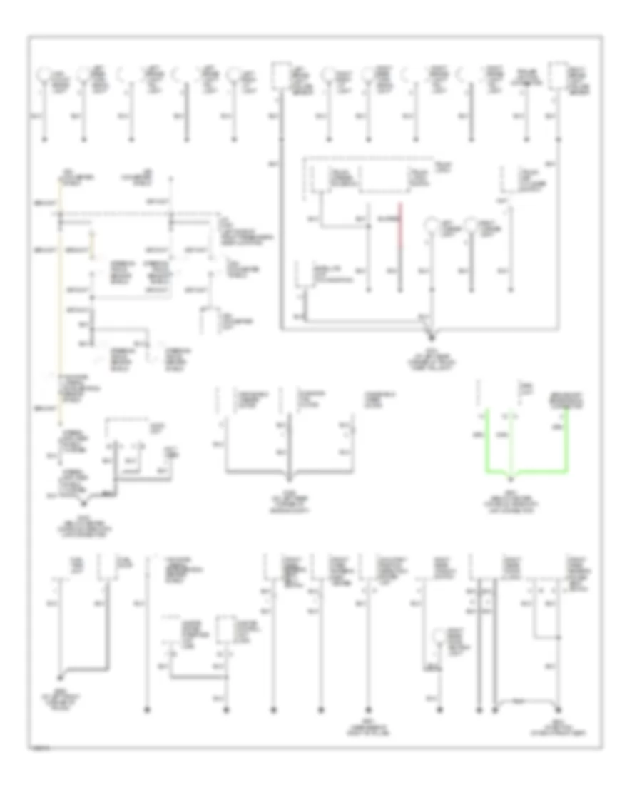
Ground Distribution Wiring Diagram (2 of 4) for Acura 3.5RL 2004
 https://portal-diagnostov.com/license.html
Automotive Electricians Portal FZCO
Automotive Electricians Portal FZCO
https://portal-diagnostov.com/license.html
https://portal-diagnostov.com/license.html
Automotive Electricians Portal FZCO
Automotive Electricians Portal FZCOList of elements for Ground Distribution Wiring Diagram (2 of 4) for Acura 3.5RL 2004:
- (not used) c403
- (not used) c502
- Accessory power socket
- Automatic lighting control unit
- C401
- C403
- C406
- C502
- C651
- Canada
- Cigarette lighter relay
- Clock
- Cruise control main switch
- Daytime running lights control unit
- Door multiplex control unit
- Driver's door key cylinder switch
- Driver's door latch
- Driver's door lock switch
- Driver's multiplex control unit
- Driver's seat belt switch
- Driver's seat heater
- Driver's seat heater switch
- Front passenger's seat heater switch
- Front seat heater relay
- G251 (on right rear of engine compartment)
- G602 (at right front corner of trunk)
- G603
- G651 (near base of left "b" pillar)
- G681 (at bottom of left front seat)
- Gauge assembly
- Glove box light
- Immobilizer control unit
- Keyless receiver unit
- Left rear door ashtray light
- Left rear door latch
- Left rear window switch
- Lumbar support switch
- Moon- roof close relay
- Moon- roof motor shield
- Moon- roof open relay
- Navi- gation display unit (if equipped)
- Navigation unit (if equipped)
- Power seat control unit
- Power window control unit
- Power window master switch relay
- Power window relay
- Select/ reset switch
- Steering column control unit
- Steering column switch
- Steering lock
- Stereo amplifier
- Trunk opener switch
- Turn signal/ hazard relay
- Under-dash fuse/relay box (behind left kick panel)
- Underhood relay box b (on right rear corner of engine compt)
- Usa
- Vsa hydraulic pressure sensor shield
- Vsa modulator/ control unit
- Yaw rate/ lateral accel- eration shield
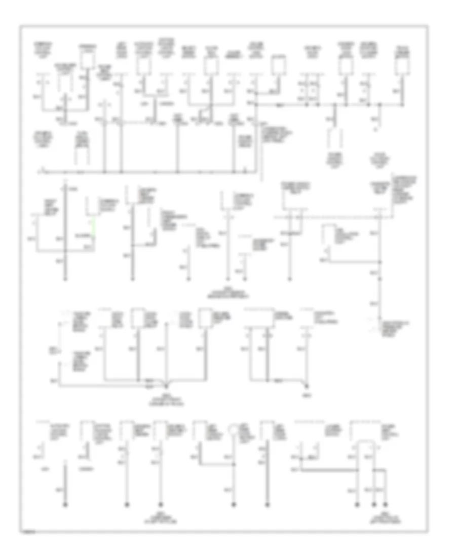
Ground Distribution Wiring Diagram (3 of 4) for Acura 3.5RL 2004
 https://portal-diagnostov.com/license.html
Automotive Electricians Portal FZCO
Automotive Electricians Portal FZCO
https://portal-diagnostov.com/license.html
https://portal-diagnostov.com/license.html
Automotive Electricians Portal FZCO
Automotive Electricians Portal FZCOList of elements for Ground Distribution Wiring Diagram (3 of 4) for Acura 3.5RL 2004:
- (canada)
- (except canada)
- (w/o navigation) (w/ navigation)
- A/t gear position switch
- Ash- tray light
- Audio unit
- Automatic dimming mirror
- Blower motor high relay
- Blower motor relay
- Cigarette lighter
- Climate control unit
- Combi- nation light switch
- Cruise control unit
- Data link connector (dlc)
- Driver's vanity mirror light
- Fan control unit
- Fog light switch (usa)
- Front ashtray panel
- Front ceiling light
- Front passen- ger's door key cylinder switch
- Front passen- ger's door latch
- Front passen- ger's door lock switch
- Front passenger's vanity mirror light
- G401 (behind left kick panel)
- G402 (behind right kick panel)
- G404 (behind right kick panel)
- Gauge assembly
- Left power mirror (w/ heated mirrors)
- Multiplex control inspection connector
- Onstar buttons & microphone homelink unit
- Park pin switch
- Passen- ger's multi- plex con- trol unit
- Passen- ger's multi- plex control unit
- Power mirror control unit
- Power mirror switch
- Power trans- istor
- Rear ceiling light
- Rear window defogger switch
- Right power mirror (w/ heated mirrors)
- Steering column control unit
- Trunk opener main switch
- Vsa converter unit
- Vsa modulator/ control unit
- Wind- shield wiper/ washer switch
Ground Distribution Wiring Diagram (4 of 4) for Acura 3.5RL 2004
 https://portal-diagnostov.com/license.html
Automotive Electricians Portal FZCO
Automotive Electricians Portal FZCO
https://portal-diagnostov.com/license.html
https://portal-diagnostov.com/license.html
Automotive Electricians Portal FZCO
Automotive Electricians Portal FZCOList of elements for Ground Distribution Wiring Diagram (4 of 4) for Acura 3.5RL 2004:
- (not used)
- Audio unit
- Front pass- enger's power seat switch
- Front pass- enger's seat belt switch
- Front pass- enger's seat heater
- Fuel pump
- Fuel tank unit
- G302 (on left rear corner of engine compt)
- G403 (below center console, near data link connector)
- G601 (near base of right "b" pillar)
- G641 (at bottom of right front seat)
- G652 (at left front corner of trunk)
- G701 (at left rear corner of trunk, near taillight)
- G801 (below center console, near data link connector)
- High mount brake light
- J/c c487 (left side of front passenger's side floor pan)
- Left back- up light
- Left brake light failure sensor
- Left brake light/ tail- light
- Left license light
- Left rear turn signal light
- Occupant position detection system unit
- Onstar control unit (usa)
- Onstar system interface unit (usa)
- Radiator fan motor
- Right back- up light
- Right brake light failure sensor
- Right brake light/ tail- light
- Right license light
- Right rear door ashtray light
- Right rear door latch
- Right rear turn signal light
- Right rear window switch
- Satellite unit (w/ navigation)
- Srs memory erase signal connector
- Srs unit
- Steering angle sensor shield
- Stereo amplifier shield (w/ bose)
- Trailer lighting connector
- Trunk key cylinder switch
- Trunk latch
- Trunk latch switch
- Trunk opener solenoid
- Vsa converter shield
- Vsa converter unit
- Windshield washer motor
- Windshield wiper motor
- Yaw rate/ lateral acceleration sensor shield
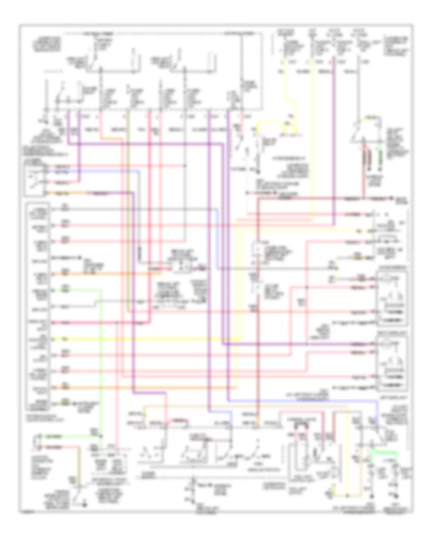
HEADLIGHTS
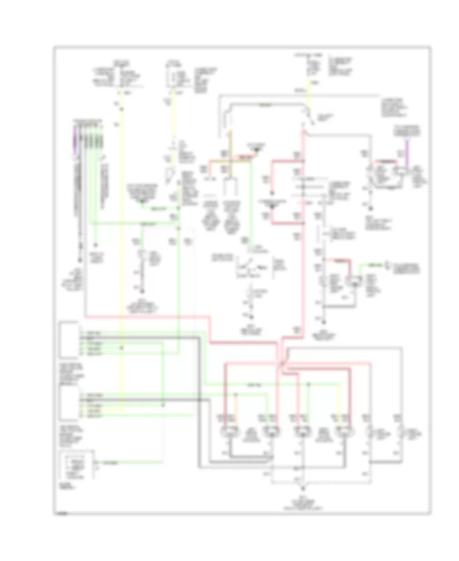
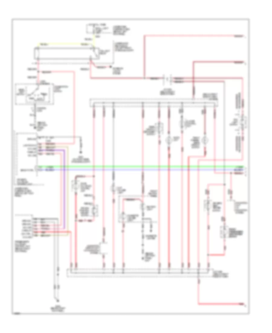
Headlights Wiring Diagram, with DRL for Acura 3.5RL 2004
 https://portal-diagnostov.com/license.html
Automotive Electricians Portal FZCO
Automotive Electricians Portal FZCO
https://portal-diagnostov.com/license.html
https://portal-diagnostov.com/license.html
Automotive Electricians Portal FZCO
Automotive Electricians Portal FZCOList of elements for Headlights Wiring Diagram, with DRL for Acura 3.5RL 2004:
- (behind left kick panel) headlight diode
- (behind left kick panel) under-dash fuse/relay box
- (not used)
- (on left front of engine compt) under-hood relay box a
- (on left front of engine compt) underhood relay box c
- (on right rear of engine compt) g251
- A/t reverse relay
- A22
- B16
- B20
- Battery fuse 31 120a
- Battery input
- Brake indicator control
- Brake/ park input
- C16
- C301
- C305
- C306
- C307
- C331
- C353
- C403
- C405
- C406
- C651
- Combination light switch fog light switch
- Daytime running lights control unit
- Defogger system
- Dimmer relay
- Dimmer switch
- Driver's multiplex control unit
- Drl indicator light
- Drl indicator light control
- Drl output
- Exterior lights system
- Flash-to- pass switch
- Fog light relay
- Fog light switch light
- Fr fog fuse 20a
- G201 (behind right headlight)
- G301 (on left front corner of engine compt)
- G401 (behind left kick panel)
- G651 (near base of left "b" pillar)
- Gauge assembly
- Gauge relay
- Ground
- Head
- Head- light relay control
- Headlight high beam relay
- Headlight low beam relay
- Headlight on input
- Headlight switch
- Hi beam relay input
- Hi beam/ drl mode control
- High
- High beam indicator light
- Hot at all times
- Hot in on
- Hot in on or start
- Igniter
- Ignition input
- Instrument cluster system
- Interior lights system
- Inverter
- J/c c456 (below right side of dash)
- Junction connector c421 (at base of steering column)
- L head- light high fuse 48 10a
- L head- light low fuse 46 20a
- Left fog light
- Left headlight
- Low
- Low beam cut relay
- Meter fuse 55 15a
- Meter sun roof fuse 13 7.5a
- Off
- On ind light
- Park
- Parking brake input
- Parking brake switch (at left kick panel, at park brake lever)
- Pnk
- R head- light high fuse 49 10a
- R head- light low fuse 45 20a
- Red
- Right fog light
- Right headlight
- Running light fuse 10 10a
- Running light fuse 12 7.5a
- Seats system
- Small light fuse 1 15a
- Taillight relay (on left front of engine compt, in underhood relay box "c")
- Under-dash fuse/relay box (behind left kick panel)
- Under-dash fuse/relay box (behind left kick panel)
- Under-hood fuse/relay box (on left side of engine compt)
- Underhood relay box c (on left front of engine compt)
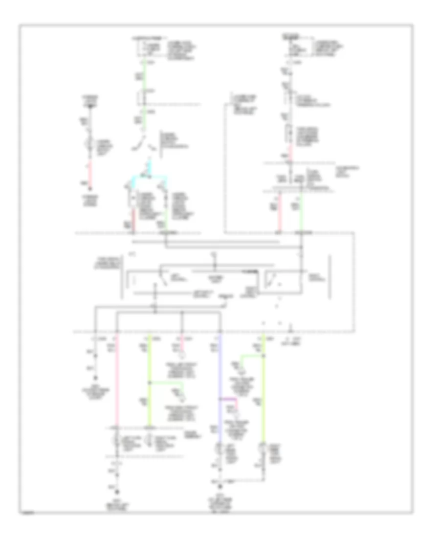
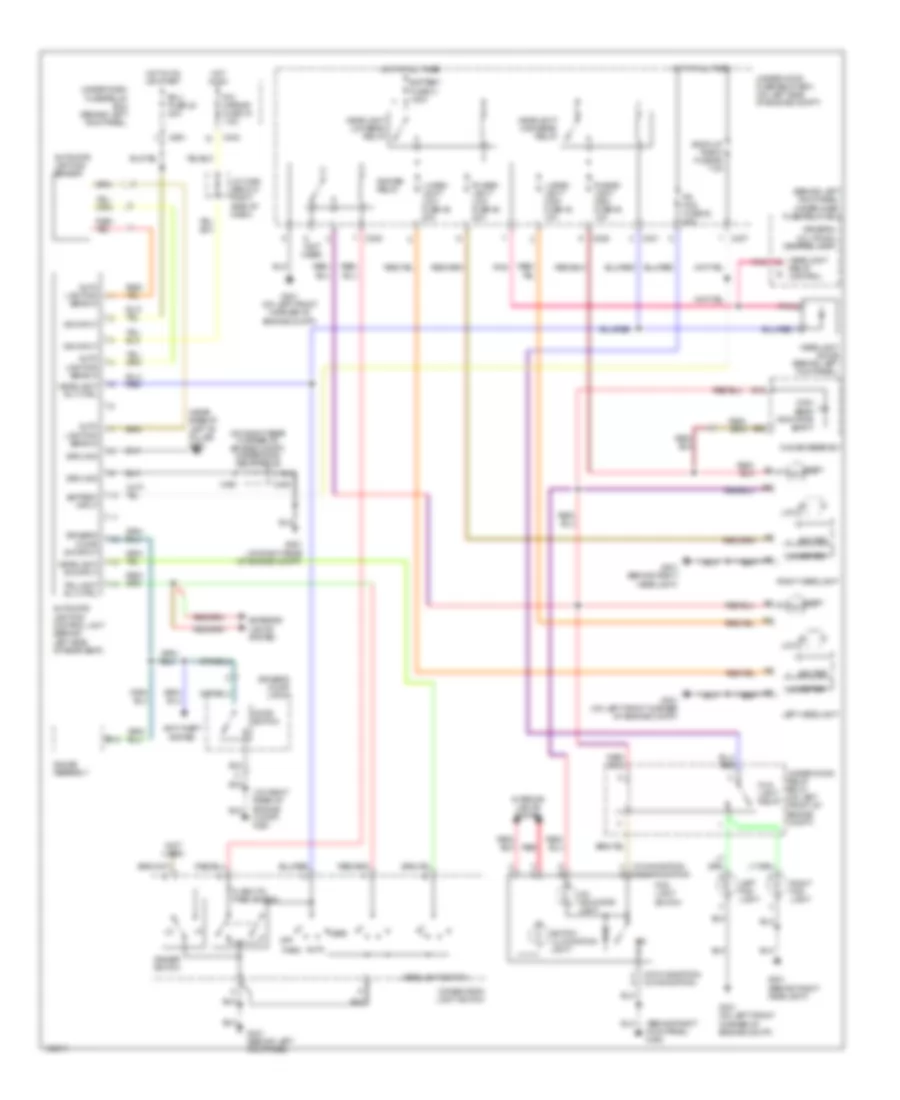
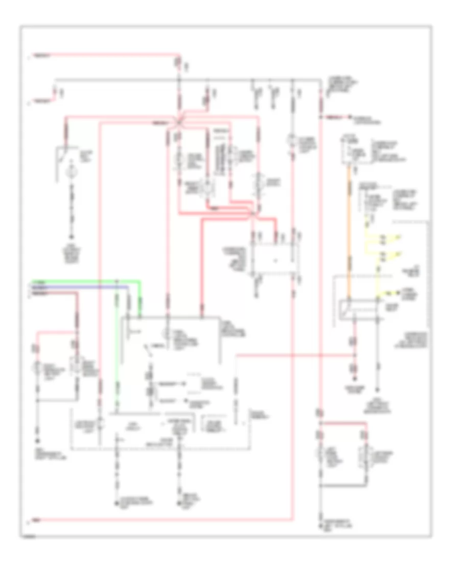
Headlights Wiring Diagram, without DRL for Acura 3.5RL 2004
 https://portal-diagnostov.com/license.html
Automotive Electricians Portal FZCO
Automotive Electricians Portal FZCO
https://portal-diagnostov.com/license.html
https://portal-diagnostov.com/license.html
Automotive Electricians Portal FZCO
Automotive Electricians Portal FZCOList of elements for Headlights Wiring Diagram, without DRL for Acura 3.5RL 2004:
- (behind left kick panel) under-dash fuse/relay box
- (behind right kick panel) g402
- (near base of left "b" pillar) g651
- (not used)
- (on right rear corner of engine compt) underhood relay box b
- (on right rear of engine compt) g251
- (w/ navigation)
- (w/o navigation)
- Anti-theft system
- Auto
- Auto lighting sens in
- Automatic lighting control unit (behind left side of rear seat)
- Automatic lighting sensor
- B14
- B16
- B20
- Back up radio fuse 56 7.5a
- Battery fuse 31 120a
- Battery input
- C301
- C305
- C306
- C307
- C403
- C406
- C651
- Combination light switch
- Dimmer relay
- Dimmer switch
- Door switch
- Driver's door latch
- Driver's door sw input
- Driver's multiplex control unit
- Ecu fuse 20 20a
- Exterior lights system
- Flash-to- pass switch
- Fog light relay
- Fog light switch
- Fr fog fuse 53 20a
- G201 (behind right headlight)
- G251 (on right rear of engine compt)
- G301 (on left front corner of engine compt)
- G401 (behind left kick panel)
- Gauge assembly
- Ground
- Head
- Headlight
- Headlight diode (behind left kick panel)
- Headlight high beam relay
- Headlight low beam relay
- Headlight rly ctrl
- Headlight sw input
- Headlight switch
- High
- High beam indicator light
- Hot at all times
- Hot in on
- Hot in on or start
- Ign input
- Igniter
- Interior lights system
- Inverter
- J/c c456 (below right side of dash)
- L head- light high fuse 48 10a
- L head- light low fuse 46 20a
- Left fog light
- Left headlight
- Low
- Off
- On indicator light
- Park
- Pnk
- R head- light high fuse 49 10a
- R head- light low fuse 45 20a
- R/c mirror fuse 19 7.5a
- Red
- Relay control
- Right fog light
- Right headlight
- Switch illumination light
- Taillight rly ctrl
- Under-dash fuse/relay box (behind left kick panel)
- Under-hood fuse/relay box (on left side of engine compt)
- Under-hood relay box c (on left front of engine compt)
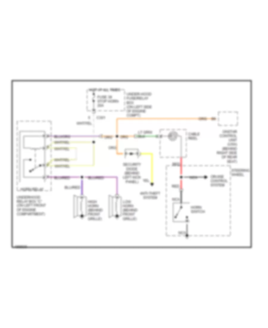
HORN
Horn Wiring Diagram for Acura 3.5RL 2004
 https://portal-diagnostov.com/license.html
Automotive Electricians Portal FZCO
Automotive Electricians Portal FZCO
https://portal-diagnostov.com/license.html
https://portal-diagnostov.com/license.html
Automotive Electricians Portal FZCO
Automotive Electricians Portal FZCOList of elements for Horn Wiring Diagram for Acura 3.5RL 2004:
- Anti-theft system
- C301
- Cable reel
- Cruise control system
- Fuse 39 stop horn 20a
- High horn (behind front grille)
- Horn relay
- Horn switch
- Hot at all times
- Low horn (behind front grille)
- Nca
- Onstar control unit (usa) (behind right side of rear seat)
- Red
- Security diode (behind left kick panel)
- Steering wheel
- Under-hood fuse/relay box (on left side of engine compt)
- Underhood relay box "c" (on left front of engine compartment)
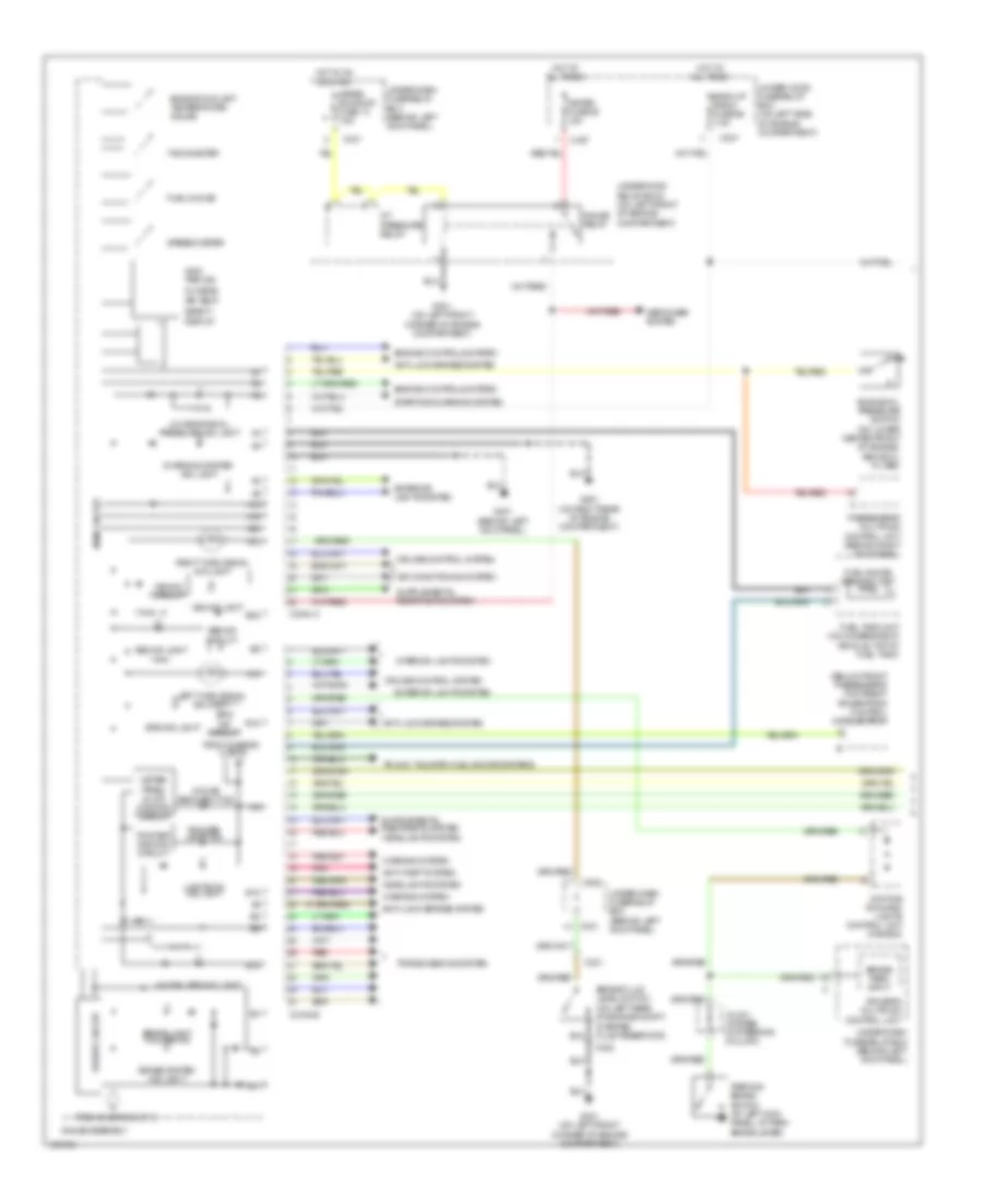
INSTRUMENT CLUSTER
Instrument Cluster Wiring Diagram (1 of 2) for Acura 3.5RL 2004
 https://portal-diagnostov.com/license.html
Automotive Electricians Portal FZCO
Automotive Electricians Portal FZCO
https://portal-diagnostov.com/license.html
https://portal-diagnostov.com/license.html
Automotive Electricians Portal FZCO
Automotive Electricians Portal FZCOList of elements for Instrument Cluster Wiring Diagram (1 of 2) for Acura 3.5RL 2004:
- (below front passenger's footrest) powertrain control module (pcm)
- A/t pressure relay
- A10
- A12
- A13
- A17
- A18
- A19
- A20
- Abs ind circuit
- Abs ind light
- Air conditioning system
- Anti-lock brakes system
- Anti-theft system
- B15
- B18
- B19
- B22
- Back up radio fuse 56 7.5a
- Brake fluid level switch (on left rear of engine compt, in brake fluid reservoir)
- Brake light failure ind
- Brake system ind light
- Brake/ park input
- C307
- C321
- C322
- C331
- C502
- Charging system ind light
- Conn a
- Conn b
- Cruise control system
- Daytime running lights control unit (canada)
- Defogger system
- Driver circuit
- Driver's multiplex control unit
- Engine controls system
- Engine coolant temperature gauge
- Engine oil pressure switch (on lower center front of engine, above oil filter)
- Exterior lights system
- From diagram 2 of 2
- Fuel gauge
- Fuel gauge sending unit
- Fuel tank unit (on underside of vehicle, top of fuel tank)
- G251 (on right rear of engine compartment)
- G301 (on left front corner of engine compartment)
- G401 (behind left kick panel)
- Gauge assembly
- Gauge backlight ind
- Gauge relay
- Headlights system
- Hot at all times
- Hot in on or start
- Immobilizer ind light
- Interior lights system
- J/c 421 (at base of steering column)
- Left turn signal ind light
- Lights-on ind light
- Low engine oil pressure ind light
- Main circuit
- Meter fuse 55 15a
- Meter panel & lcd dimming circuit
- Meter sunroof fuse 13 7.5a
- Odo/ trip ind
- Outside air temp
- Parking brake switch (at left kick panel, at park brake lever)
- Passenger's multiplex control unit (behind right kick panel)
- Pnk
- Pointer dimming circuit
- Pointer light ind
- Red
- Right turn signal ind light
- Safety display
- Speedometer
- Srs ind circuit
- Srs ind light
- Starting/charging system
- Tachometer
- Transmissions system
- Trunk, tailgate, fuel doors systems
- Under-dash fuse/relay box (behind left kick panel)
- Under-hood fuse/relay box (on left side of engine compartment)
- Underhood relay box c (on left front of engine compartment)
- Vsa ind circuit
- Vsa ind light
- Warning system
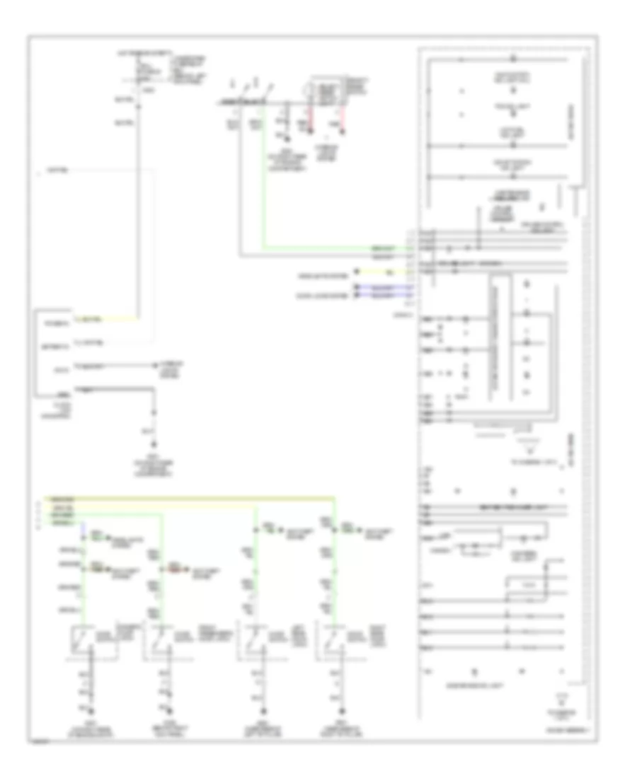
Instrument Cluster Wiring Diagram (2 of 2) for Acura 3.5RL 2004
 https://portal-diagnostov.com/license.html
Automotive Electricians Portal FZCO
Automotive Electricians Portal FZCO
https://portal-diagnostov.com/license.html
https://portal-diagnostov.com/license.html
Automotive Electricians Portal FZCO
Automotive Electricians Portal FZCOList of elements for Instrument Cluster Wiring Diagram (2 of 2) for Acura 3.5RL 2004:
- (canada)
- A/t & cruise control lights-on circuit
- A21
- A22
- Anti-theft system
- B10
- B11
- B12
- B13
- B14
- B16
- B20
- B21
- B23
- B24
- B25
- B26
- B27
- B28
- B29
- B30
- Battery in
- C502
- Canada
- Clock (w/o navigation)
- Conn c
- Cruise control circuit
- Cruise control ind light
- Dim in
- Door locks system
- Door switch
- Drive circuit
- Driver's door latch
- Drl ind light
- Ecu fuse 20 20a
- Front passenger's door latch
- G251 (on right rear of engine compartment)
- G251 (on right rear of engine compt)
- G402 (behind right kick panel)
- G601 (near base of right "b" pillar)
- G651 (near base of left "b" pillar)
- Gauge assembly
- Gnd
- Headlights system
- High beam ind light
- Hot in on or start
- Interior lights system
- Left rear door latch
- Low fuel ind light
- Main circuit
- Maintenance required ind
- Malfunction ind light (mil)
- Power in
- Red
- Reset
- Right rear door latch
- Seat belt reminder light
- Select
- Select/ reset switch
- Select/ reset switch light
- Side air bag ind light
- Tcs ind light
- To diagram 1 of 2
- To diagram 1 of 2
- Under-dash fuse/relay box (behind left kick panel)
- Usa
- Vsa activation ind light
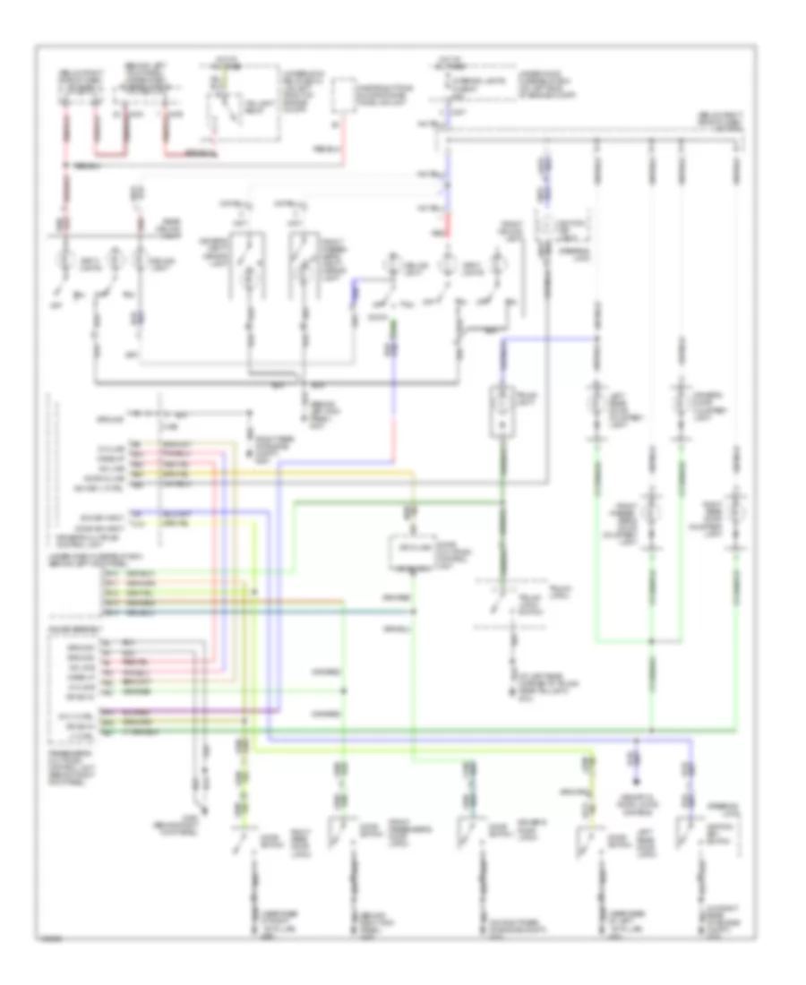
INTERIOR LIGHTS
Courtesy Lamps Wiring Diagram for Acura 3.5RL 2004
 https://portal-diagnostov.com/license.html
Automotive Electricians Portal FZCO
Automotive Electricians Portal FZCO
https://portal-diagnostov.com/license.html
https://portal-diagnostov.com/license.html
Automotive Electricians Portal FZCO
Automotive Electricians Portal FZCOList of elements for Courtesy Lamps Wiring Diagram for Acura 3.5RL 2004:
- (at left rear corner of trunk, near taillight) g701
- (behind left kick panel) g401
- (behind left kick panel) under-dash fuse/relay box
- (behind right kick panel) g402
- (below right side of dash) j/c c456
- (below right side of dash) j/c c464
- (near base of left ``b" pillar)
- (near base of right ``b" pillar) g601
- (on right rear of engine compt) g251
- (right rear of engine compt) g251
- A-d line
- A10
- A22
- A23
- B10
- B11
- B12
- B13
- B14
- B18
- B21
- B22
- B23
- B25
- C15
- C307
- C406
- Ceiling light
- D-a line
- Door
- Door d-line
- Door multiplex control unit
- Door sw input
- Door switch
- Dr d-line
- Dr sw in
- Dr switch
- Driver's door courtesy light
- Driver's door latch
- Driver's multiplex control unit
- Driver's vanity mirror light
- Front ceiling light
- Front passen- ger's door courtesy light
- Front passen- ger's vanity mirror light
- Front passenger's door latch
- G402 (behind right kick panel)
- G651
- Gauge assembly
- Ground
- Hot at all times
- Ign key input
- Ign key lt ctrl
- Ignition key light
- Ignition key switch
- Int lt ctrl
- Interior lights fuse 57 20a
- Left rear door courtesy light
- Left rear door latch
- Lt ctrl
- Memory & door locks systems
- Off
- Onstar buttons & microphone/ home link unit
- Passenger's multiplex control unit (behind right kick panel)
- Rear ceiling light
- Red
- Right rear door courtesy light
- Right rear door latch
- Spot- lights
- Steering lock
- Taillight relay
- Trunk latch
- Trunk latch switch
- Trunk light
- Under-dash fuse/relay box (behind left kick panel)
- Under-hood fuse/relay box (on left side of engine compt)
- Underhood relay box c (on left front of engine compt)
- Wake up
Instrument Illumination Wiring Diagram (1 of 2) for Acura 3.5RL 2004
 https://portal-diagnostov.com/license.html
Automotive Electricians Portal FZCO
Automotive Electricians Portal FZCO
https://portal-diagnostov.com/license.html
https://portal-diagnostov.com/license.html
Automotive Electricians Portal FZCO
Automotive Electricians Portal FZCOList of elements for Instrument Illumination Wiring Diagram (1 of 2) for Acura 3.5RL 2004:
- (behind left kick panel) g401
- (below right side of dash) j/c c456
- (canada) (usa)
- (usa) (canada)
- A-d line
- A10
- A11
- A12
- A15
- A19
- A22
- Ashtray light
- Audio unit
- Auto
- B10
- B22
- Bright ctrl
- C11
- C353
- C406
- Cigarette lighter
- Cigarette lighter light
- Climate control unit
- Combination light switch
- Cup holder light
- D-a line
- Dim ctrl
- Door multiplex control unit
- Driver's multiplex control unit
- Driver's seat heater switch
- Driving position memory switch
- Exterior lights system
- Fog light switch
- Front ashtray panel
- Front front passenger's passenger's seat heater seat heater switch switch
- Front passen- ger's window switch
- G251 (on right rear of engine compt)
- G402 (behind right kick panel)
- Ground
- Head
- Head- light switch
- Hot at all times
- J/c c464 (below right side of dash)
- Lights on in
- Navigation display unit (w/ navigation system)
- Navigation unit (w/ navigation system)
- Off
- Park
- Passenger's multiplex control unit (behind right kick panel)
- Rear window defogger switch
- Red
- Small light fuse 1 15a
- Taillight relay
- Under-dash fuse/relay box (behind left kick panel)
- Underhood relay box c (on left front of engine compt)
- W/ navigation
- W/o navigation
- Wake up
Instrument Illumination Wiring Diagram (2 of 2) for Acura 3.5RL 2004
 https://portal-diagnostov.com/license.html
Automotive Electricians Portal FZCO
Automotive Electricians Portal FZCO
https://portal-diagnostov.com/license.html
https://portal-diagnostov.com/license.html
Automotive Electricians Portal FZCO
Automotive Electricians Portal FZCOList of elements for Instrument Illumination Wiring Diagram (2 of 2) for Acura 3.5RL 2004:
- (behind left kick panel) g401
- (near base of left ``b" pillar) g651
- (not used)
- (on right rear of engine compt) g251
- A/t gear position console light
- A/t reverse relay
- A10
- A22
- B18
- C307
- C331
- C402
- C402 (not used)
- C403
- C405
- C501
- C502
- C651
- C906
- Cancel
- Clock (except navigation)
- Cruise control circuit
- Cruise control main switch
- Dash lights brightness controller
- Dash lights brightness controller light
- Defogger system
- Exterior lights system
- G251 (on right rear of engine compt)
- G301 (left front corner of engine compt)
- G601 (near base of right ``b" pillar)
- Gauge assembly
- Gauge backlight ind
- Gauge relay
- Glove box light
- Hazard warning switch
- Hot at all times
- Hot in on or start
- Left rear door ashtray light
- Left rear window switch
- Lights-on indicator light
- Main circuit
- Meter fuse 55 15a
- Meter panel & lcd dimming circuit
- Meter sun roof fuse 13 7.5a
- Navigation system
- Red
- Right rear door ashtray light
- Right rear window switch
- Select/ reset switch
- Under-dash fuse/relay box (behind left kick panel)
- Under-hood fuse/relay box (on left side of engine compt)
- Underhood relay box c (on left front of engine compt)
- Vsa off switch
- W/ navigation
- W/o navigation
- Wiper/ washer system
MEMORY SYSTEMS
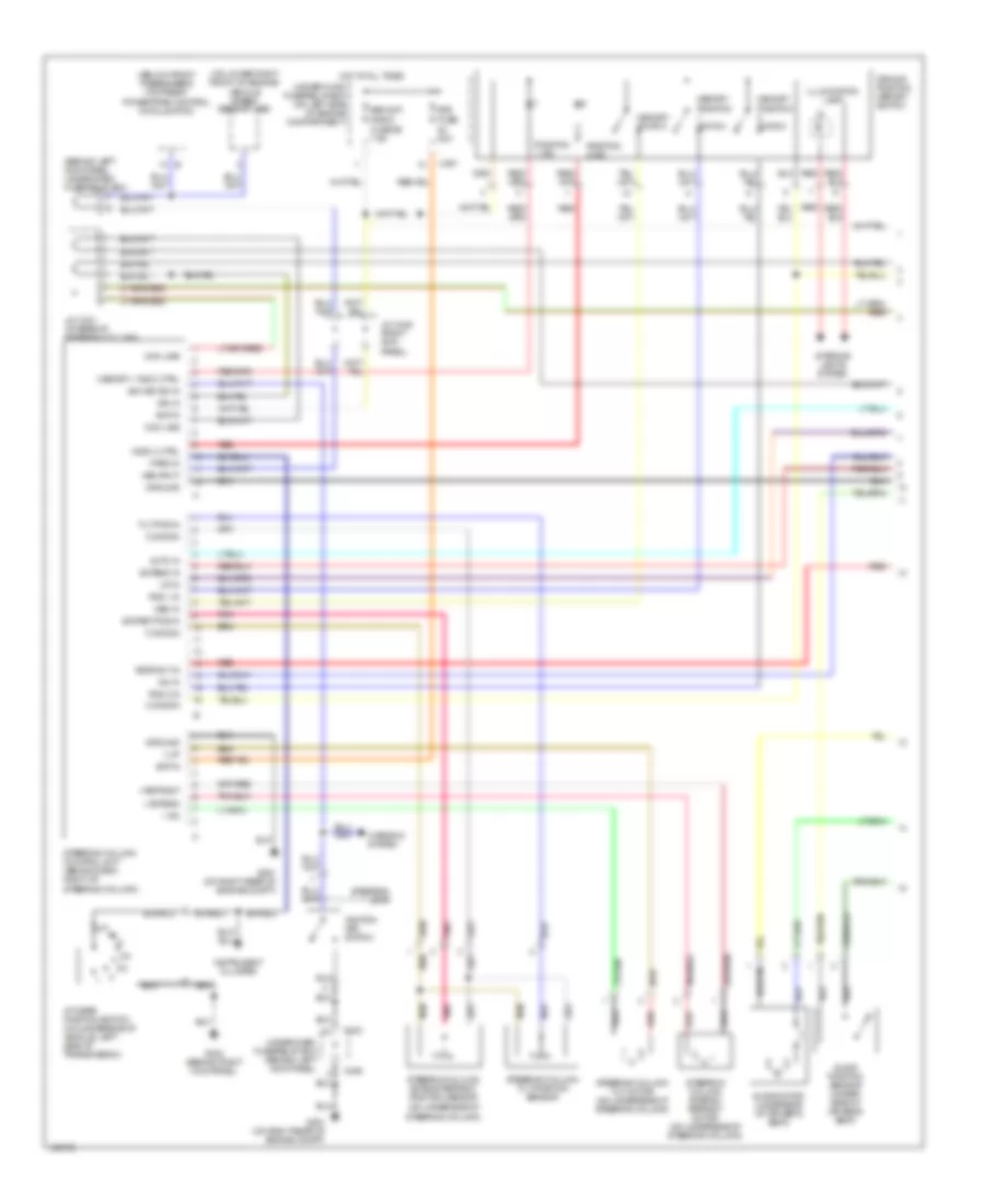
Front Power Seats & Steering Column Wiring Diagram (1 of 2) for Acura 3.5RL 2004
 https://portal-diagnostov.com/license.html
Automotive Electricians Portal FZCO
Automotive Electricians Portal FZCO
https://portal-diagnostov.com/license.html
https://portal-diagnostov.com/license.html
Automotive Electricians Portal FZCO
Automotive Electricians Portal FZCOList of elements for Front Power Seats & Steering Column Wiring Diagram (1 of 2) for Acura 3.5RL 2004:
- (behind left kick panel) under-dash fuse/relay box
- (below front passenger's footrest) powertrain control module (pcm)
- (on lower right front of engine) vehicle speed sensor (vss)
- (on underside of steering column)
- + dn
- + extend
- + retract
- + up
- 20a
- A/t gear position switch (on underside of vehicle, left side of transmission)
- Auto in
- Backup,
- Bat in
- C307
- C403
- C406
- Com line
- Common
- Dn in
- Driving position memory switch
- Ets
- Ext/ret pos in
- Extend in
- Fuse
- Fuse 56 7.5a
- G251 (on right rear of engine compt)
- G402 (behind right kick panel)
- Ground
- Hot at all times
- Ign in
- Ign key sw in
- Ignition key switch
- Illumination lamp
- Indic 2 ctrl
- Instrument cluster
- Interior lights system
- J/c c421 (at base of steering column)
- J/c c448 (right kick panel)
- Mem in
- Memory 1 indic ctrl
- Memory position switch
- Memory switch
- Park in
- Pnk
- Pos 1 in
- Pos 2 in
- Position 1 ind
- Position 2 ind
- Radio
- Red
- Retract in
- Slide motor (underside of driver's seat)
- Slide position sensor (under- side of driver's seat)
- Steering column control unit (behind dash, right of steering column)
- Steering column extend/ retract motor (on underside of steering column)
- Steering column extend/retract position sensor
- Steering column tilt motor (on underside of steering column)
- Steering column tilt position sensor
- Steering lock
- Tilt pos in
- Under-dash fuse/relay box (behind left kick panel)
- Under-hood fuse/relay box (on left side of engine compartment)
- Up in
- Vss input
- Warning system
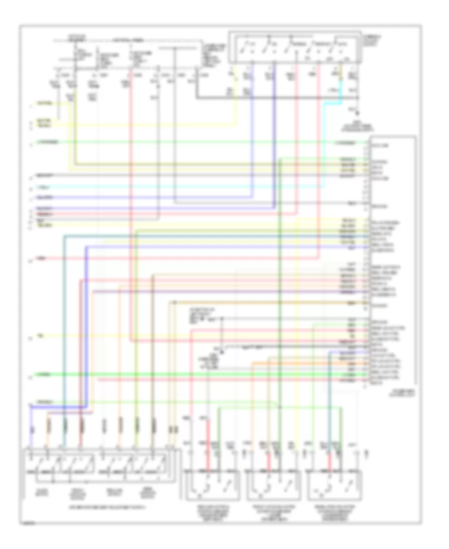
Front Power Seats & Steering Column Wiring Diagram (2 of 2) for Acura 3.5RL 2004
 https://portal-diagnostov.com/license.html
Automotive Electricians Portal FZCO
Automotive Electricians Portal FZCO
https://portal-diagnostov.com/license.html
https://portal-diagnostov.com/license.html
Automotive Electricians Portal FZCO
Automotive Electricians Portal FZCOList of elements for Front Power Seats & Steering Column Wiring Diagram (2 of 2) for Acura 3.5RL 2004:
- (at bottom of left front seat) g681
- Auto
- Back
- Bat in
- C403
- C405
- C406
- C651
- C686
- C687
- C688
- C689
- C690
- Com line
- Common
- Down
- Dr power seat fuse 11 20a
- Dr power seat fuse 8 20a
- Driver's power seat adjustment switch
- Ecu fuse 20 20a
- Extend
- For
- Fr dn in
- Fr u/d mot ctrl
- Fr u/d pos sen
- Fr up in
- Front up-down motor & position sensor (under driver's seat)
- Front up/down switch
- G251 (on right rear of engine compt)
- G651 (near base of left "b" pillar)
- Ground
- Hot at all times
- Hot in on or start
- Ign in
- Off
- Power seat control unit
- Rear dn in
- Rear u/d mot ctrl
- Rear u/d pos in
- Rear up in
- Rear up-down motor & position sensor (underside of driver's seat)
- Rear up/down switch
- Recl back in
- Recl for in
- Recl mot ctrl
- Recl pos sen
- Recline motor & position sensor (inside driver's seat-back)
- Recline switch
- Red
- Retract
- Sld pos sen
- Slide back in
- Slide for in
- Slide mot ctrl
- Slide switch
- Steering column switch
- U/d mot ctrl
- Under-dash fuse/relay box (behind left kick panel)
Memory Mirrors Wiring Diagram for Acura 3.5RL 2004
 https://portal-diagnostov.com/license.html
Automotive Electricians Portal FZCO
Automotive Electricians Portal FZCO
https://portal-diagnostov.com/license.html
https://portal-diagnostov.com/license.html
Automotive Electricians Portal FZCO
Automotive Electricians Portal FZCOList of elements for Memory Mirrors Wiring Diagram for Acura 3.5RL 2004:
- Back-up, radio fuse 56 7.5a
- Bat in
- C307
- C402
- C748
- C752
- C768
- Comm line
- Common
- Defogger system
- G401 (behind left kick panel)
- G402 (behind right kick panel)
- Ground
- Hot at all times
- Hot in on
- Ign in
- J/c c421 (at base of steering column)
- J/c c456 (below right side of dash)
- L swing sensor in
- L tilt sensor in
- L/r mot cont
- Left
- Left power mirror
- Left/ right
- Mirror defogger switch
- Mirror selector switch
- On ind
- Position sensor
- Power mirror control unit
- Power mirror switch
- R swing sensor in
- R tilt sensor in
- R/c mirror fuse 19 7.5a
- Right
- Right power mirror
- Steering column control unit (behind dash, right of steering column)
- Sw 1 in
- Sw 2 in
- Sw 3 in
- Switch 1
- Switch 2
- Switch 3
- U/d mot cont
- Under-dash fuse/relay box (behind left kick panel)
- Under-hood fuse/relay box (on left side of engine compartment)
- Up/ down
NAVIGATION
Navigation Wiring Diagram for Acura 3.5RL 2004
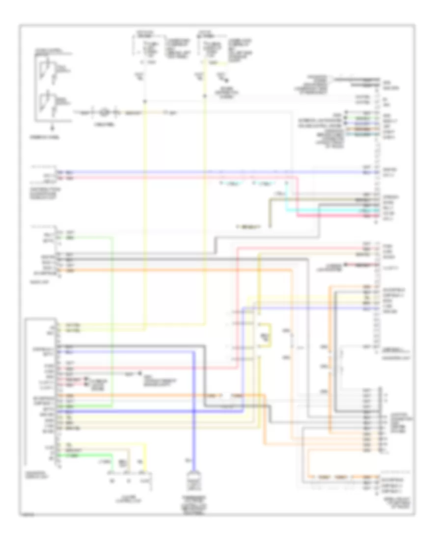 https://portal-diagnostov.com/license.html
Automotive Electricians Portal FZCO
Automotive Electricians Portal FZCO
https://portal-diagnostov.com/license.html
https://portal-diagnostov.com/license.html
Automotive Electricians Portal FZCO
Automotive Electricians Portal FZCOList of elements for Navigation Wiring Diagram for Acura 3.5RL 2004:
- Acc
- Audio unit
- Audio unit input
- B sig
- Back lt
- Back switch
- Bus (+)
- Bus (-)
- C sig
- C307
- C404
- Cable reel
- Climate control unit
- Clk2
- Cruise control system
- Diag n
- Diag p
- Disp bus (+)
- Disp bus (-)
- Exterior lights system
- Fuse 4 acc radio 10a
- Fuse 56 back up radio 7.5a
- G sig
- G251 (on right rear of engine compt)
- G603
- Gnd
- Gnd gps
- Gnd rg
- Gnd sig
- Gps
- Hot at all times
- Hot in on or acc
- Illum (+)
- Illum (-)
- Interior lights system
- Junction connector c488 (center of dash)
- Mic (+)
- Mic (-)
- Mic sh
- Navigation display unit
- Navigation service check connector (at right front of trunk)
- Navigation system gps antenna (under right side of rear shelf)
- Navigation unit
- Nca
- Onstar buttons & microphone homelink unit
- Passenger's multiplex control unit (behind right kick panel)
- Pnk
- Power distribution system
- R sig
- Red
- Rg lt
- Satellite unit (at left side of trunk)
- Scty1
- Scty2
- Sh disp bus
- Sh dsp bus
- Sh rg
- Sh sig
- Steering wheel
- Strg sw
- Talk switch
- Under-dash fuse/relay box (behind left kick panel)
- Under-hood fuse/relay box (on left side of engine compt)
- Voice control switch
- Vsp
PASSIVE RESTRAINTS
Passive Restraints Wiring Diagram for Acura 3.5RL 2004
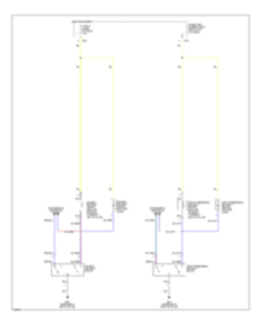 https://portal-diagnostov.com/license.html
Automotive Electricians Portal FZCO
Automotive Electricians Portal FZCO
https://portal-diagnostov.com/license.html
https://portal-diagnostov.com/license.html
Automotive Electricians Portal FZCO
Automotive Electricians Portal FZCOList of elements for Passive Restraints Wiring Diagram for Acura 3.5RL 2004:
- C404
- C651
- Driver's seat belt switch
- Driver's seat belt tension reducer diode
- Driver's seat belt tension reducer solenoid (at base of left "b" pillar)
- Front passenger's seat belt switch
- Front passenger's seat belt tension reducer diode
- Front passenger's seat belt tension reducer solenoid (at base of right "b" pillar)
- Fuse 13 meter sun roof 7.5a
- G601 (near base of right "b" pillar)
- G651 (near base of left "b" pillar)
- Hot in on or start
- Under-dash fuse/relay box (behind left kick panel)
POWER DISTRIBUTION
Power Distribution Wiring Diagram (1 of 5) for Acura 3.5RL 2004
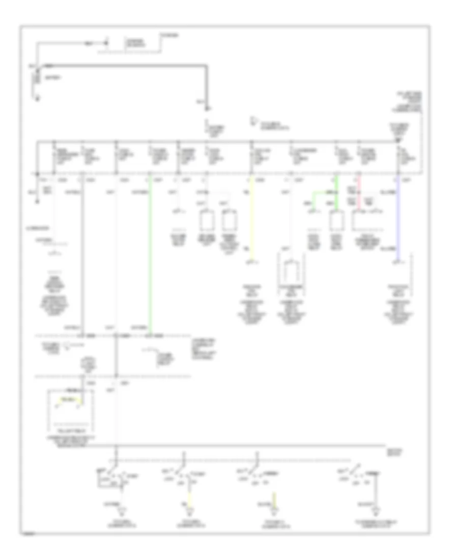 https://portal-diagnostov.com/license.html
Automotive Electricians Portal FZCO
Automotive Electricians Portal FZCO
https://portal-diagnostov.com/license.html
https://portal-diagnostov.com/license.html
Automotive Electricians Portal FZCO
Automotive Electricians Portal FZCOList of elements for Power Distribution Wiring Diagram (1 of 5) for Acura 3.5RL 2004:
- (on left side of engine compt) under-hood fuse/relay box
- Acc
- Alternator
- Battery
- Battery fuse 31 120a
- Blower motor relay
- C303
- C304
- C305
- C306
- C307
- C329
- C330
- C353
- C901
- Condenser fan fuse 50 20a
- Condenser fan relay
- Cooling fan fuse 47 20a
- Door lock fuse 44 20a
- Fr fog fuse 53 20a
- Front fog light relay
- Front passenger's power seat switch
- Fuse box fuse 34 50a
- Heater motor fuse 37 40a
- Ig sw fuse 35 50a
- Ignition switch
- Keyless receiver unit
- Lock
- Moon- roof close relay
- Moon- roof open relay
- Off
- Passen- ger's multiplex control unit
- Power seat as fuse 52 30a
- Power window fuse 36 40a
- Power window relay
- Radiator fan relay
- Rear defroster fuse 33 40a
- Rear window defogger relay
- Small light fuse 1 15a
- Start
- Starter
- Starter solenoid
- Sun roof fuse 51 30a
- T101
- Taillight relay
- To fuse 13 (diagram 4 0f 5)
- To fuse 3 (diagram 3 0f 5)
- To fuse 39 (diagram 2 of 5)
- To fuse 4 (diagram 3 0f 5)
- To fuse 5 (diagram 3 of 5)
- To fuse 55 (diagram 2 of 5)
- To starter cut relay (diagram 4 of 5)
- Under-dash fuse/relay box (behind left kick panel)
- Underhood relay box "a" (on left front of engine compt)
- Underhood relay box "c" (on left front of engine compt)
- Underhood relay box "c" (on left front of engine compt)
Power Distribution Wiring Diagram (2 of 5) for Acura 3.5RL 2004
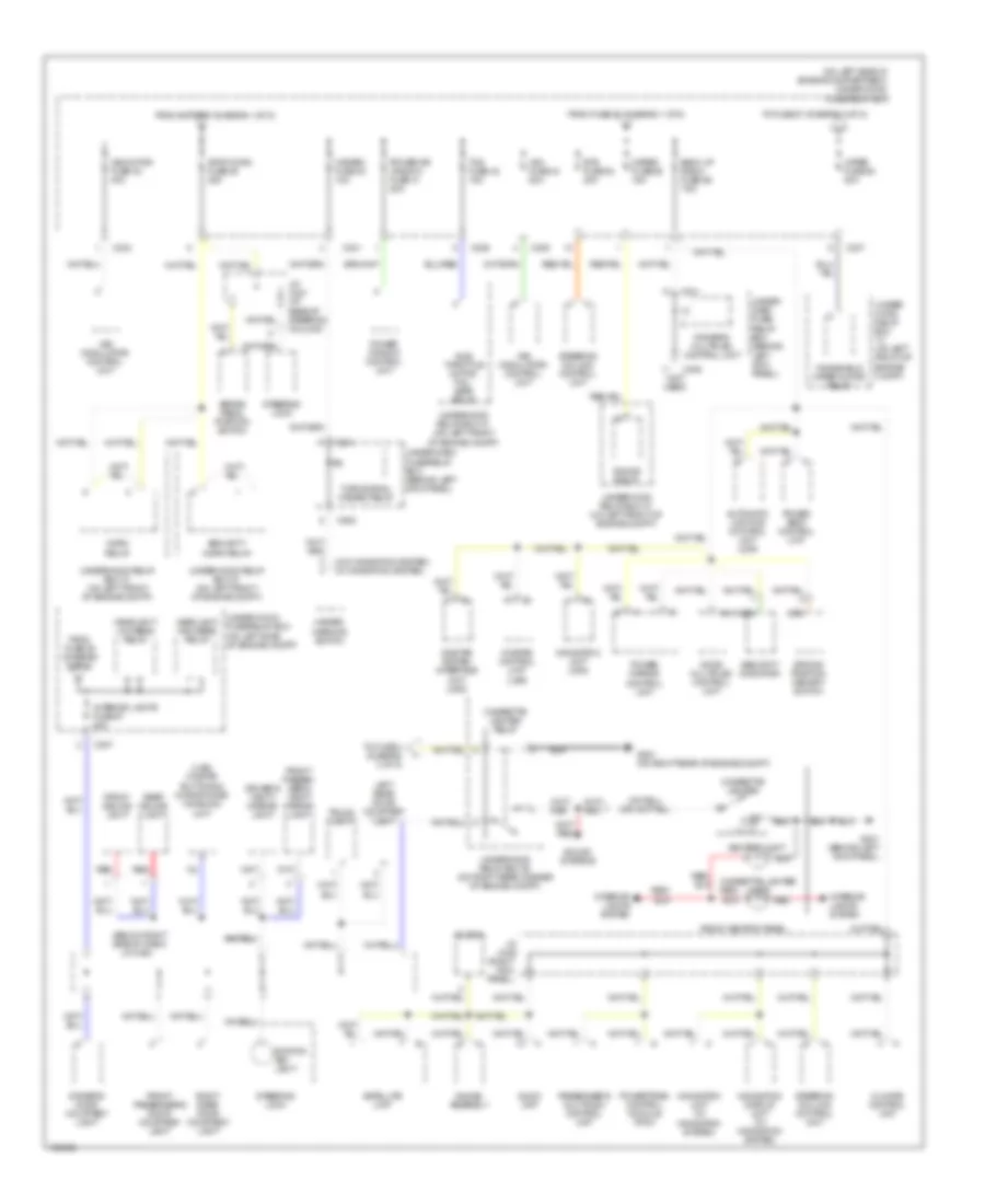 https://portal-diagnostov.com/license.html
Automotive Electricians Portal FZCO
Automotive Electricians Portal FZCO
https://portal-diagnostov.com/license.html
https://portal-diagnostov.com/license.html
Automotive Electricians Portal FZCO
Automotive Electricians Portal FZCOList of elements for Power Distribution Wiring Diagram (2 of 5) for Acura 3.5RL 2004:
- (below right side of dash)
- (not used)
- (on left side of engine compartment) under-hood fuse/relay box
- (usa) onstar buttons & microphone/ homelink unit
- (w/o navigation system) (w/ navigation system)
- Ashtray light
- Audio unit
- Automatic lighting control unit (usa)
- Back up radio fuse 56 7.5a
- Brake pedal position switch
- C301
- C303
- C305
- C306
- C307
- C331
- C405
- C502
- Cigarette lighter
- Cigarette lighter light
- Cigarette lighter relay
- Climate control unit
- Clock
- Door multiplex control unit
- Driver's door courtesy light
- Driver's multiplex control unit
- Driver's vanity mirror light
- Driving position memory switch
- Ets fuse 54 20a
- From battery (diagram 1 of 5)
- From fuse 53 (diagram 1 of 5)
- From fuse 58 (diagram 2 of 5)
- Front ashtray panel
- Front ceiling light
- Front passen- ger's vanity mirror light
- Front passenger's door courtesy light
- G251 (on right rear of engine compt)
- G401 (behind left kick panel)
- Gauge assembly
- Gauge relay
- Hazard fuse 40 10a
- Hazard warning switch
- Headlight high beam relay
- Headlight low beam relay
- Horn relay
- Ignition key light
- Interior lights fuse 57 20a
- Interior lights system
- J/c c421 (at base of steering column)
- J/c c448 (right kick panel)
- J/c c464
- Left rear door courtesy light
- Meter fuse 55 15a
- Navigation display unit (w/ navigation system)
- Navigation unit (usa)
- Navigation unit (w/ navigation system)
- Onstar control unit (usa)
- Onstar system interface unit (usa)
- Passenger's multiplex control unit
- Power dr window fuse 41 20a
- Power mirror control unit
- Power seat control unit
- Power window control unit
- Powertrain control module (pcm)
- Rear ceiling light
- Red
- Right rear door courtesy light
- Satellite unit
- Security horn relay
- Security indicator
- Sound systems
- Steering column control unit
- Steering lock
- Stop horn fuse 39 20a
- Sub throttle motor fail- safe relay
- Tcs fuse 42 15a
- To fuse 4 (diagram 3 of 5)
- To fuse 57 (diagram 2 of 5)
- Trunk light
- Turn signal/ hazard relay
- Under- dash fuse/ relay box (behind left kick panel)
- Under- hood relay box "c" (on left front of engine compt)
- Under-dash fuse/relay box (behind left kick panel)
- Under-hood fuse/relay box (on left side of engine compt)
- Underhood relay box "a" (on left front of engine compt)
- Underhood relay box "b" (on right rear corner of engine compt)
- Underhood relay box "c" (on left front of engine compt)
- Vsa fuse 43 20a
- Vsa modulator/ control unit
- Vsa motor fuse 32 40a
- Windshield wiper motor relay
- Wiper fuse 58 30a
Power Distribution Wiring Diagram (3 of 5) for Acura 3.5RL 2004
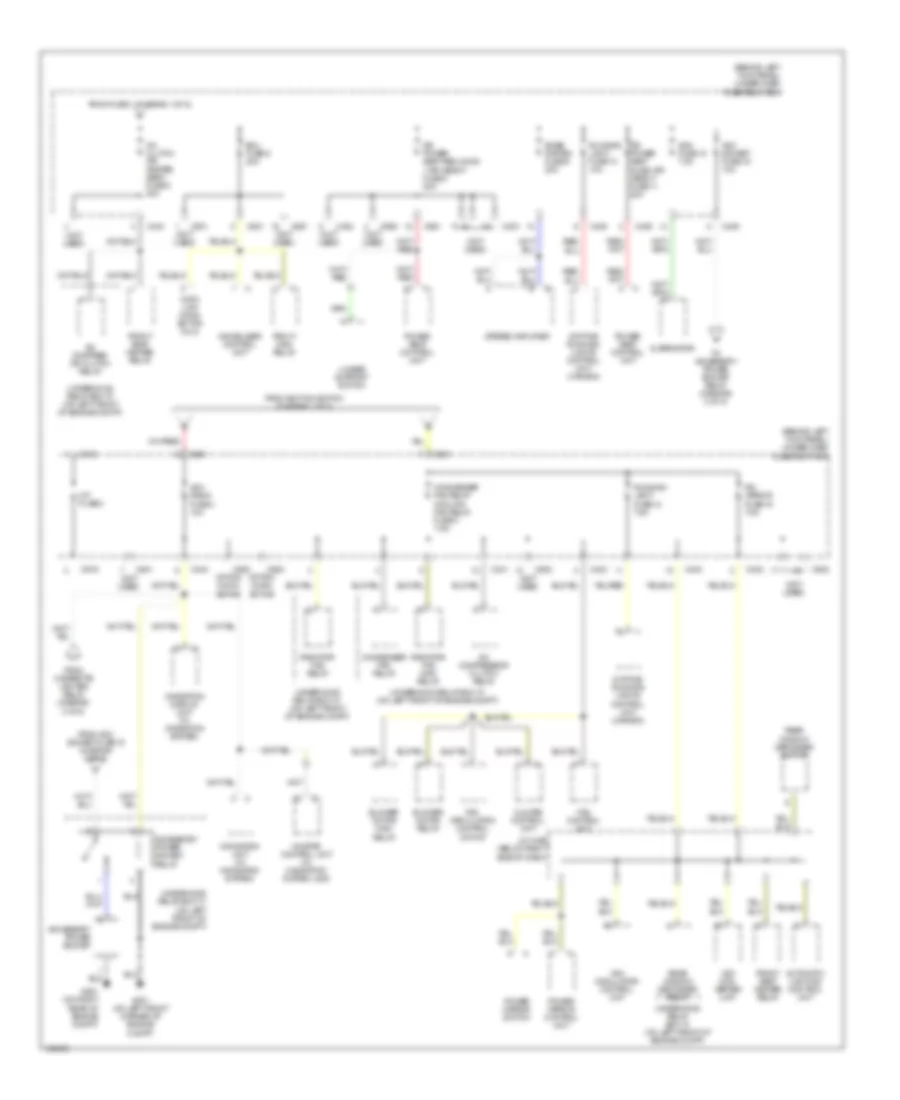 https://portal-diagnostov.com/license.html
Automotive Electricians Portal FZCO
Automotive Electricians Portal FZCO
https://portal-diagnostov.com/license.html
https://portal-diagnostov.com/license.html
Automotive Electricians Portal FZCO
Automotive Electricians Portal FZCOList of elements for Power Distribution Wiring Diagram (3 of 5) for Acura 3.5RL 2004:
- (behind left kick panel) under-dash fuse/relay box
- (not used)
- A/c clutch (fr heated seat) fuse 5 20a
- A/c compres- or clutch relay
- A/c compressor clutch relay
- Acc radio fuse 4 10a
- Acc socket fuse 16 10a
- Accessory power socket
- Accessory power socket relay
- Acg fuse 15 7.5a
- Alternator
- Automatic lighting control unit
- Blower motor high relay
- Blower motor relay
- Bose system fuse 9 20a
- C331
- C402
- C403
- C404
- C405
- C406
- C501
- C502
- C651
- C901
- C906
- C919
- C920
- C922
- Climate control unit
- Condenser fan relay
- Condenser fan relay cooling fan relay fuse 3 7.5a
- Data link conn- ector (dlc)
- Daytime running lights control unit (canada)
- Dr power seat reclining + rr height fuse 8 20a
- Dr power seat slide +fr height fuse 11 20a
- Ecu fuse 6 20a
- Fan control unit
- From acc socket fuse 16 (diagram 3 of 5)
- From cigarette lighter relay (diagram 2 of 5)
- From fuse 1 (diagram 1 of 5)
- From ignition switch (diagram 1 of 5)
- Front seat heater relay
- G251 (on right rear of engine compt)
- G301 (on left front corner of engine compt)
- Immobilizer control unit
- J/c c456 (below right side of dash)
- Lumbar support switch
- Navigation display unit (w/ navigation system)
- Navigation unit (w/ navigation system)
- Onstar control unit (w/ navigation system, usa)
- Op fuse 2
- Option conn- ector
- Pgm-fi main relay
- Power mirror control unit
- Power mirror switch
- Power seat control unit
- R/c mirror fuse 19 7.5a
- Radiator fan main relay
- Radiator fan relay
- Re- circulation control motor
- Rear window defogger relay
- Rear window defogger switch
- Running light fuse 10 10a
- Running light fuse 12 7.5a
- Stereo amplifier
- To accessory power socket relay (diagram 3 of 5)
- Underhood relay box "a" (on left front of engine compt)
- Underhood relay box "c" (on left front of engine compt)
- Vsa con- verter unit
- Vsa modulator/ control unit
Power Distribution Wiring Diagram (4 of 5) for Acura 3.5RL 2004
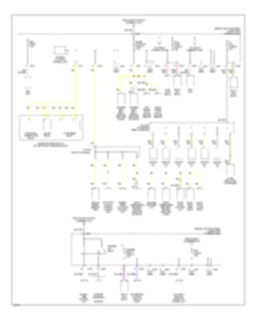 https://portal-diagnostov.com/license.html
Automotive Electricians Portal FZCO
Automotive Electricians Portal FZCO
https://portal-diagnostov.com/license.html
https://portal-diagnostov.com/license.html
Automotive Electricians Portal FZCO
Automotive Electricians Portal FZCOList of elements for Power Distribution Wiring Diagram (4 of 5) for Acura 3.5RL 2004:
- (behind left kick panel) under-dash fuse/relay box
- (not used)
- (right kick panel)
- A/t reverse relay
- Automatic dimming mirror (canada, usa)
- C331
- C403
- C404
- C405
- C406
- C501
- C651
- C801
- C901
- Driver's multiplex control unit
- Driver's seat belt tension reducer diode
- Driver's seat belt tension reducer solenoid
- From fuse 22 (diagram 4 of 5)
- From ignition switch (diagram 1 of 5)
- Front passenger's seat belt tension reducer diode
- Front passenger's seat belt tension reducer solenoid
- Fuel pump fuse 22 20a
- Fuel pump relay
- Gauge relay
- Ig coil fuse 25 30a
- Ignition coil
- Imm0bil- izer control unit
- J/c c106 (at center rear of engine)
- J/c c448
- Keyless receiver unit
- Left brake light failure sensor
- Meter, sun roof fuse 13 7.5a
- Moon- roof close relay
- Moon- roof control unit
- Moon- roof open relay
- Noise reduction condenser
- Occupant position detection system unit
- Passen- ger's multiplex control unit
- Pgm-fi main relay
- Powertrain control module (pcm)
- Right brake light failure sensor
- Srs fuse 23 7.5a
- Srs fuse 7 10a
- Srs unit
- Starter
- Starter cut relay
- Starter signal fuse 14 7.5a
- Starter solenoid
- To fuse 20 (diagram 5 of 5)
- To fuse 23 (diagram 4 of 5)
- Underhood relay box "c" (on left front of engine compt)
- Vehicle speed sensor (vss)
- Windshield wiper motor relay
Power Distribution Wiring Diagram (5 of 5) for Acura 3.5RL 2004
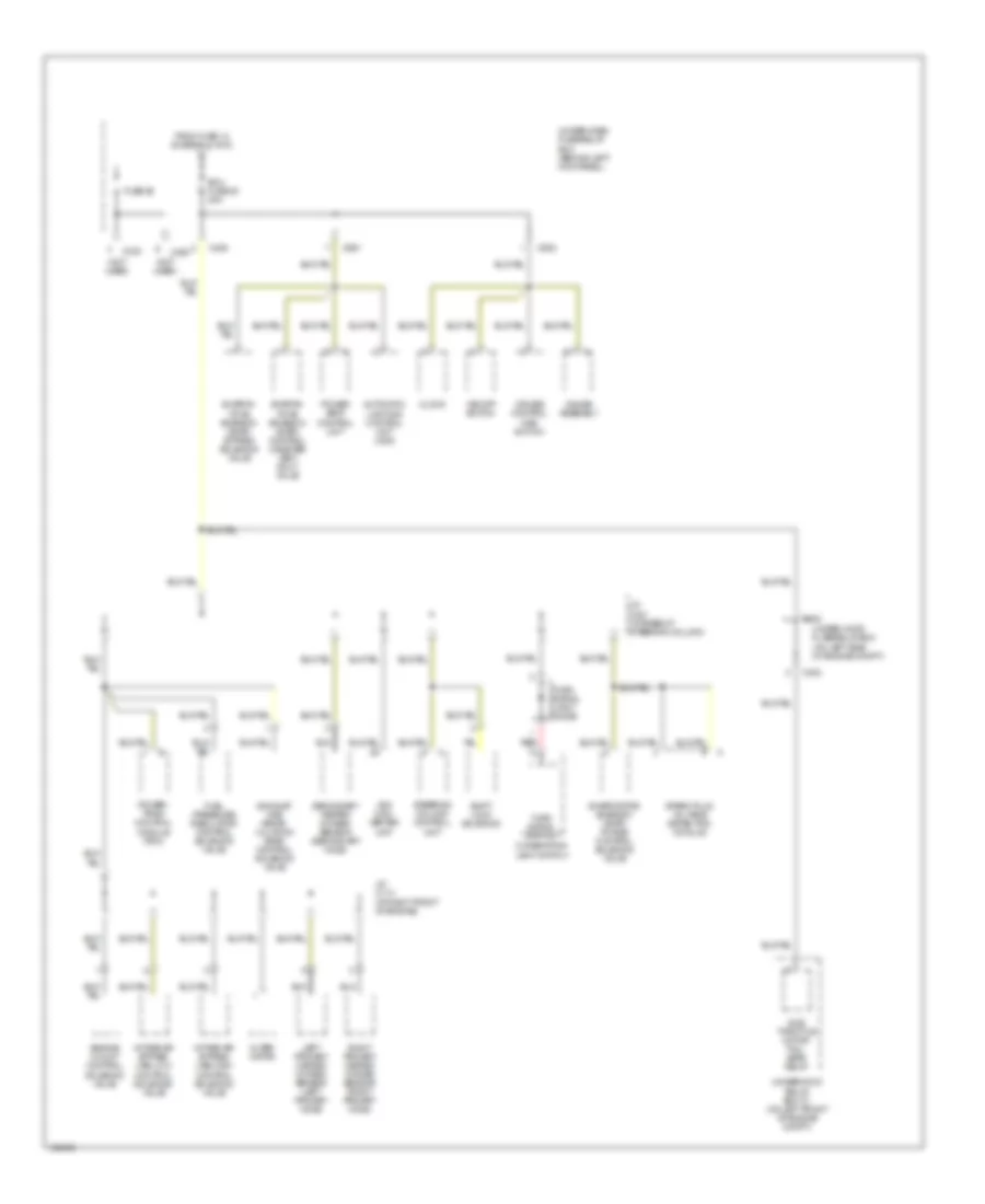 https://portal-diagnostov.com/license.html
Automotive Electricians Portal FZCO
Automotive Electricians Portal FZCO
https://portal-diagnostov.com/license.html
https://portal-diagnostov.com/license.html
Automotive Electricians Portal FZCO
Automotive Electricians Portal FZCOList of elements for Power Distribution Wiring Diagram (5 of 5) for Acura 3.5RL 2004:
- (not used)
- Alter- nator
- Automatic lighting control unit (usa)
- C302
- C330
- C405
- C460
- C502
- C651
- Clock
- Combination light switch
- Cruise control main switch
- Ecu fuse 20 20a
- Engine mount control solenoid valve
- Evapor- ative emission (evap) bypass solenoid valve
- Evapor- ative emission (evap) control canister vent shut valve
- Evaporative emission (evap) purge control solenoid valve
- Exhaust gas recir- culation (egr) control solenoid valve
- From fuse 13 (diagram 4 of 5)
- Fuel pressure regulator control solenoid valve
- Fuse 26
- Gauge assembly
- Intake air bypass (iab) high control solenoid valve
- Intake air bypass (iab) low control solenoid valve
- J/c c114 (at right front of engine)
- J/c c421 (at base of steering column)
- Left primary heated oxygen sensor (left primary ho2s)
- Power seat control unit
- Power- train control module (pcm)
- Red
- Right primary heated oxygen sensor (right primary ho2s)
- Secondary heated oxygen sensor (secondary ho2s)
- Shift lock solenoid
- Spark plug voltage detection module
- Steering column control unit
- Sub throttle motor fail- safe relay
- Turn signal light diode
- Turn signal switch
- Under-dash fuse/relay box (behind left kick panel)
- Under-hood fuse/relay box (on left side of engine compt)
- Underhood relay box "c" (on left front of engine compt)
- Vsa con- verter unit
- Vsa off switch
POWER DOOR LOCKS
Power Door Locks Wiring Diagram for Acura 3.5RL 2004
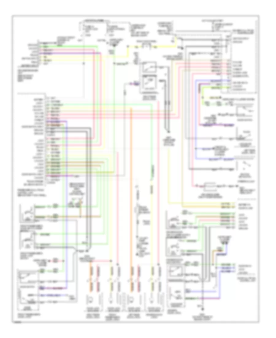 https://portal-diagnostov.com/license.html
Automotive Electricians Portal FZCO
Automotive Electricians Portal FZCO
https://portal-diagnostov.com/license.html
https://portal-diagnostov.com/license.html
Automotive Electricians Portal FZCO
Automotive Electricians Portal FZCOList of elements for Power Door Locks Wiring Diagram for Acura 3.5RL 2004:
- (at left rear corner of trunk, near taillight) g701
- (at right front corner of trunk) g602
- (behind right side of rear seat) on star control unit
- (not used)
- (right kick panel) j/c c448
- 7.5a
- A-d line
- Battery
- Battery in
- Battery input
- Buzzer cntrl
- C306
- C307
- C403
- C404
- C406
- C651
- Conn a
- Conn b
- D-a line
- Door d-line
- Door lock actuator
- Door multiplex control unit
- Door sw in
- Door switch
- Door switch input
- Driver's door key cylinder switch (in driver's door)
- Driver's door latch
- Driver's door lock switch
- Driver's multiplex control unit
- Front passenger's door key cylinder switch
- Front passenger's door latch
- Front passenger's door lock switch
- Fuse 44 door lock 20a
- Fuse 56 back up radio 7.5a
- G201 (behind right headlight)
- G251 (on right rear of engine compt)
- G402 (behind right kick panel)
- G601 (near base of right "b" pillar)
- G651 (near base of left "b" pillar)
- Ground
- Hot at all times
- Hot in on or start
- Ign key sw in
- Ignition input
- Ignition key switch
- Instrument cluster system
- Keyless buzzer (right inner fender)
- Keyless receiver unit (behind right side of rear seat)
- Knob switch
- Left rear door latch
- Lock
- Lock +
- Lock knob switch
- Memory & instrument cluster systems
- Meter sunroof fuse 13
- Panic
- Passenger's multiplex control unit (behind right kick panel)
- Pnk
- Right rear door latch
- Solenoid switch
- Steering lock
- Trunk
- Trunk latch
- Trunk opener
- Trunk opener solenoid
- Un- lock
- Un-lock
- Under-dash fuse/relay box (behind left kick panel)
- Under-hood fuse/relay box (on left side of engine compt)
- Unlock
- Unlock +
- Wakeup
POWER MIRRORS
Automatic Day/Night Mirror Wiring Diagram for Acura 3.5RL 2004
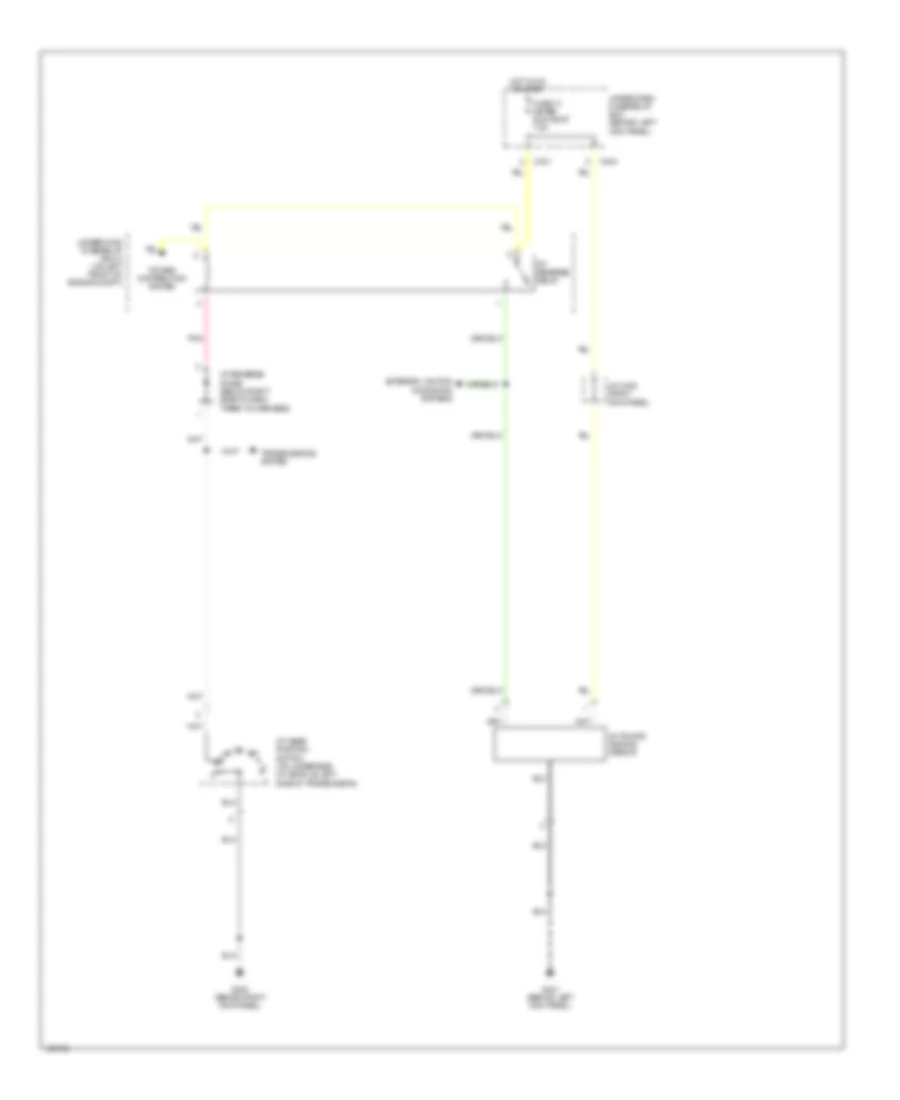 https://portal-diagnostov.com/license.html
Automotive Electricians Portal FZCO
Automotive Electricians Portal FZCO
https://portal-diagnostov.com/license.html
https://portal-diagnostov.com/license.html
Automotive Electricians Portal FZCO
Automotive Electricians Portal FZCOList of elements for Automatic Day/Night Mirror Wiring Diagram for Acura 3.5RL 2004:
- A/t gear position switch (on underside of vehicle, left side of transmission)
- A/t reverse diode (below right side of dash, taped to harness)
- A/t reverse relay
- Automatic dimming mirror
- C331
- C404
- Exterior lights & navigation systems
- Fuse 13 meter sun roof 7.5a
- G401 (behind left kick panel)
- G402 (behind right kick panel)
- Hot in on or start
- J/c c448 (right kick panel)
- Pnk
- Power distribution system
- Transmissions system
- Under-dash fuse/relay box (behind left kick panel)
- Underhood fuse/relay box c (on left front of engine compt)
POWER SEATS
Heated Seats Wiring Diagram for Acura 3.5RL 2004
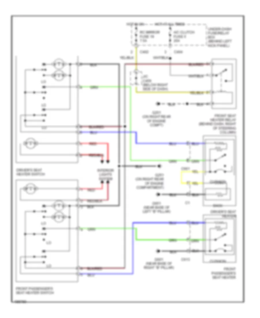 https://portal-diagnostov.com/license.html
Automotive Electricians Portal FZCO
Automotive Electricians Portal FZCO
https://portal-diagnostov.com/license.html
https://portal-diagnostov.com/license.html
Automotive Electricians Portal FZCO
Automotive Electricians Portal FZCOList of elements for Heated Seats Wiring Diagram for Acura 3.5RL 2004:
- A/c clutch fuse 5 20a
- Back
- C402
- C404
- C613
- C661
- Cushion
- Driver's seat heater
- Driver's seat heater switch
- Front passenger's seat heater
- Front passenger's seat heater switch
- Front seat heater relay (behind dash, right of steering column)
- G251 (on right rear of engine compartment)
- G251 (on right rear of engine compt)
- G601 (near base of right "b" pillar)
- G651 (near base of left "b" pillar)
- Hot at all times
- Hot in on
- Interior lights system
- J/c c456 (below right side of dash)
- Rc mirror fuse 19 7.5a
- Red
- Under-dash fuse/relay box (behind left kick panel)
Lumbar Wiring Diagram for Acura 3.5RL 2004
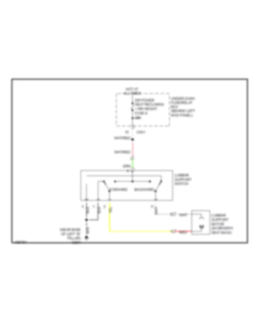 https://portal-diagnostov.com/license.html
Automotive Electricians Portal FZCO
Automotive Electricians Portal FZCO
https://portal-diagnostov.com/license.html
https://portal-diagnostov.com/license.html
Automotive Electricians Portal FZCO
Automotive Electricians Portal FZCOList of elements for Lumbar Wiring Diagram for Acura 3.5RL 2004:
- (near base of left "b" pillar) g651
- Backward
- C651
- Dr power seat reclining + rr height fuse 8 20a
- Forward
- Hot at all times
- Lumbar support motor (in driver's seat back)
- Lumbar support switch
- Red
- Under-dash fuse/relay box (behind left kick panel)
Passenger"s Power Seat Wiring Diagram for Acura 3.5RL 2004
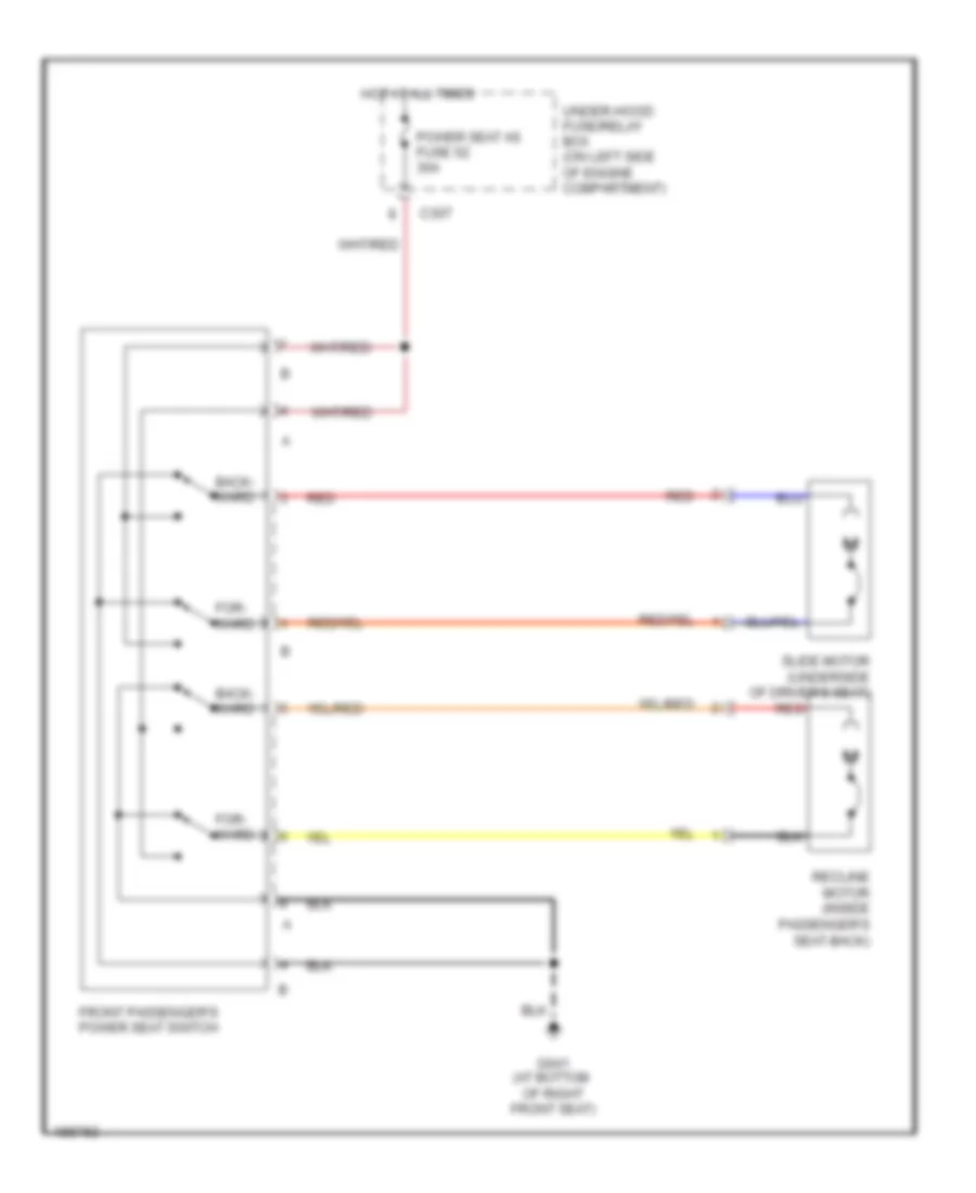 https://portal-diagnostov.com/license.html
Automotive Electricians Portal FZCO
Automotive Electricians Portal FZCO
https://portal-diagnostov.com/license.html
https://portal-diagnostov.com/license.html
Automotive Electricians Portal FZCO
Automotive Electricians Portal FZCOList of elements for Passenger"s Power Seat Wiring Diagram for Acura 3.5RL 2004:
- Back- ward
- C307
- For- ward
- Front passenger's power seat switch
- G641 (at bottom of right front seat)
- Hot at all times
- Power seat as fuse 52 30a
- Recline motor (inside passenger's seat-back)
- Red
- Slide motor (underside of driver's seat)
- Under-hood fuse/relay box (on left side of engine compartment)
POWER TOP/SUNROOF
Power Top/Sunroof Wiring Diagram for Acura 3.5RL 2004
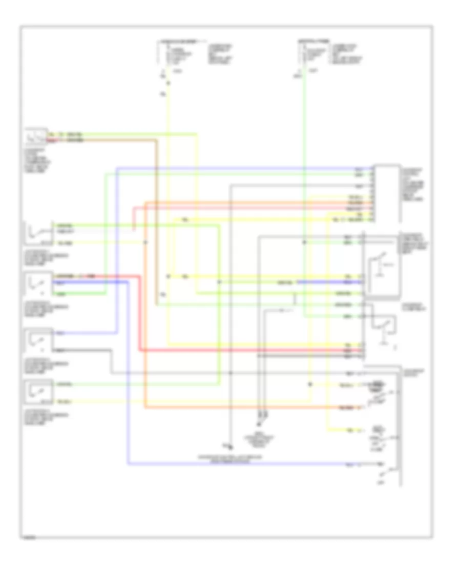 https://portal-diagnostov.com/license.html
Automotive Electricians Portal FZCO
Automotive Electricians Portal FZCO
https://portal-diagnostov.com/license.html
https://portal-diagnostov.com/license.html
Automotive Electricians Portal FZCO
Automotive Electricians Portal FZCOList of elements for Power Top/Sunroof Wiring Diagram for Acura 3.5RL 2004:
- Auto open
- C307
- C404
- Close
- G602 (at right front corner of trunk)
- Hot at all times
- Hot in on or start
- Limit switch 1 (on center underside of roof, above headliner)
- Limit switch 2 (on center underside of roof, above headliner)
- Limit switch 3 (on center underside of roof, above headliner)
- Limit switch 4 (on center underside of roof, above headliner)
- Meter, moonroof fuse 13 7.5a
- Moonroof close relay
- Moonroof control unit (on center underside of roof, above headliner)
- Moonroof control unit ground (right rear of roof)
- Moonroof motor (on center underside of roof, above headliner)
- Moonroof open relay (behind right side of rear seat)
- Moonroof switch
- Off
- Open
- Red
- Sun roof fuse 51 30a
- Tilt
- Under-dash fuse/relay box (behind left kick panel)
- Under-hood fuse/relay box (on left side of engine compt)
POWER WINDOWS
Power Windows Wiring Diagram (1 of 2) for Acura 3.5RL 2004
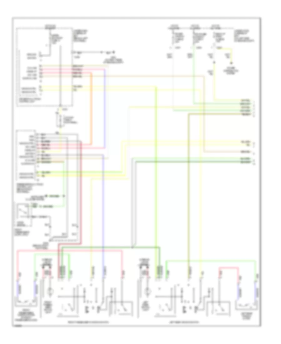 https://portal-diagnostov.com/license.html
Automotive Electricians Portal FZCO
Automotive Electricians Portal FZCO
https://portal-diagnostov.com/license.html
https://portal-diagnostov.com/license.html
Automotive Electricians Portal FZCO
Automotive Electricians Portal FZCOList of elements for Power Windows Wiring Diagram (1 of 2) for Acura 3.5RL 2004:
- A-d line
- Back-up radio fuse 56 7.5a
- C306
- C307
- C404
- C406
- D-a line
- Door d-line
- Door sw in
- Door switch
- Down
- Dr power window fuse 41 20a
- Driver's multiplex control unit
- Front passen- ger's switch light
- Front passenger's door latch
- Front passenger's window motor (in front passenger's door)
- Front passenger's window switch
- G251 (on right rear of engine compt)
- G402 (behind right kick panel)
- Gnd
- Ground
- Hot at all times
- Hot in on or start
- Ignition
- Instrument cluster system
- Interior lights system
- J/c c448 (right kick panel)
- Left rear switch light
- Left rear window motor
- Left rear window switch
- Meter sun roof fuse 13 7.5a
- Passenger's multiplex control unit (behind right kick panel)
- Power distribution system
- Power window fuse 36 40a
- Red
- Under-dash fuse/relay box (behind left kick panel)
- Under-hood fuse/relay box (on left side of engine compt)
- Wake up
- Wake-up
- Window ctrl
Power Windows Wiring Diagram (2 of 2) for Acura 3.5RL 2004
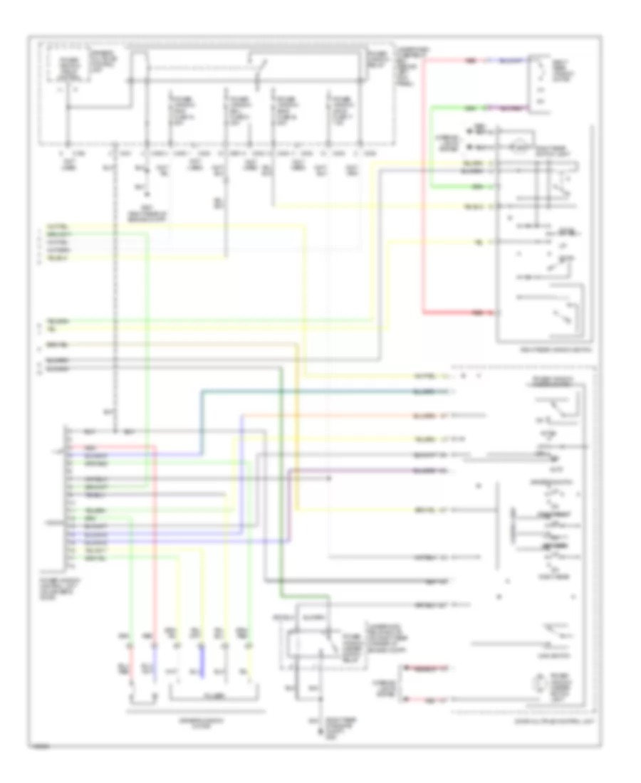 https://portal-diagnostov.com/license.html
Automotive Electricians Portal FZCO
Automotive Electricians Portal FZCO
https://portal-diagnostov.com/license.html
https://portal-diagnostov.com/license.html
Automotive Electricians Portal FZCO
Automotive Electricians Portal FZCOList of elements for Power Windows Wiring Diagram (2 of 2) for Acura 3.5RL 2004:
- (not used)
- (right rear of engine compt) g251
- + down
- + up
- Auto
- C330
- C401
- C402
- C403
- C405
- C406
- C651
- Control unit
- Door multiplex control unit
- Down
- Driver's multiplex control unit
- Driver's switch
- Driver's window motor
- G251 (right rear of engine compt)
- Interior lights system
- Left rear
- Main switch
- Off
- Power window control unit (on driver's door)
- Power window fr-r fuse 18 20a
- Power window master switch
- Power window master switch light
- Power window master switch relay
- Power window mpcs fuse 17 7.5a
- Power window relay
- Power window relay control
- Power window rr-l fuse 21 20a
- Power window rr-r fuse 24 20a
- Pulser
- Red
- Right front
- Right rear
- Right rear switch light
- Right rear window motor
- Right rear window switch
- Under-dash fuse/relay box (behind left kick panel)
- Underhood relay box "b" (on right rear corner of engine compt)
RADIO
Radio Wiring Diagram for Acura 3.5RL 2004
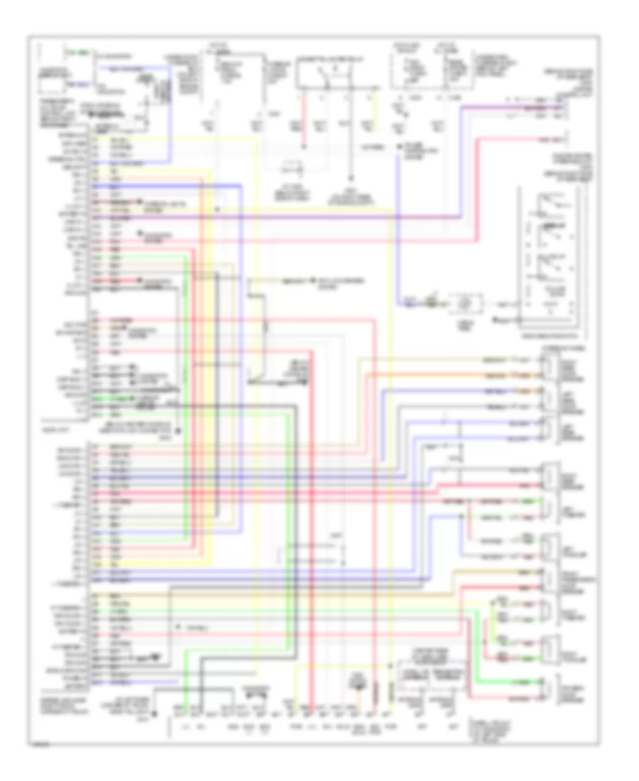 https://portal-diagnostov.com/license.html
Automotive Electricians Portal FZCO
Automotive Electricians Portal FZCO
https://portal-diagnostov.com/license.html
https://portal-diagnostov.com/license.html
Automotive Electricians Portal FZCO
Automotive Electricians Portal FZCOList of elements for Radio Wiring Diagram for Acura 3.5RL 2004:
- (+)
- (-)
- (at left rear corner of trunk, near taillight)
- (behind right side of rear seat) (usa) onstar control unit
- (below center console) g403
- (below center console, near data link connector)
- (center rear of headliner) xm antenna
- A10
- A11
- A12
- A13
- A14
- A15
- A16
- A17
- A18
- A19
- A20
- Acc pwr
- Acc radio fuse 4 10a
- Amplifier
- Ant
- Antenna in
- Antenna lead
- Anti-lock brakes system
- Audio unit
- B10
- B11
- B12
- B13
- B14
- Back-up radio fuse 56 7.5a
- Battery
- Battery in
- Bose system fuse 9 20a
- Bus (+)
- Bus (-)
- Bus shld
- C307
- C404
- C405
- Cable reel
- Cigarette lighter relay
- Disp bus (+)
- Disp bus (-)
- Driver's door speaker
- Drv door (+)
- Drv door (-)
- Front passenger's door speaker
- G251 (on right rear of engine compt)
- G403
- G603
- G701
- Gnd
- Gnd rg
- Ground
- Hot at all times
- Hot in acc or run
- Illum
- Illum (+)
- Illum (-)
- Interior lights fuse 57 20a
- Interior lights system
- J/c c464 (below right side of dash)
- L (+)
- L (-)
- L tweeter (+)
- L tweeter (-)
- L(+)
- L(-)
- Left rear door speaker
- Left rear speaker
- Left tweeter
- Left twiddler
- Lf (+)
- Lf (-)
- Line in (+)
- Line in (-)
- Lr (+)
- Lr (-)
- Lr door (+)
- Lr door (-)
- Navi- gation system
- Navigation display unit
- Navigation system
- Nca
- Onstar system interface unit (usa) (behind right side of rear seat)
- Passenger's multiplex control unit (behind right kick panel)
- Pnk
- Power distribution system
- Power in
- Pwr
- R (+)
- R (-)
- R tweeter (+)
- R tweeter (-)
- R(+)
- R(-)
- Radio antenna shield ground
- Radio remote switch
- Radio window antenna
- Rear window
- Red
- Rf (+)
- Rf (-)
- Rg lt
- Right rear door speaker
- Right rear speaker
- Right tweeter
- Right twiddler
- Rr (+)
- Rr (-)
- Rr door (+)
- Rr door (-)
- Satellite antenna
- Satellite unit (w/ navigation) (at left side of trunk)
- Security
- Seek up
- Sh disp bus
- Shield ground
- Shld
- Steering ctrl
- Steering wheel
- Stereo amplifier (right front corner of trunk)
- Sw ign in
- Tel line
- Terrestrial antenna
- Under-dash fuse/relay box (behind left kick panel)
- Under-hood fuse/relay box (on left side of engine compt)
- Volume down
- Volume up
- W/ navigation
- W/o navigation
SHIFT INTERLOCK
Shift Interlock Wiring Diagram for Acura 3.5RL 2004
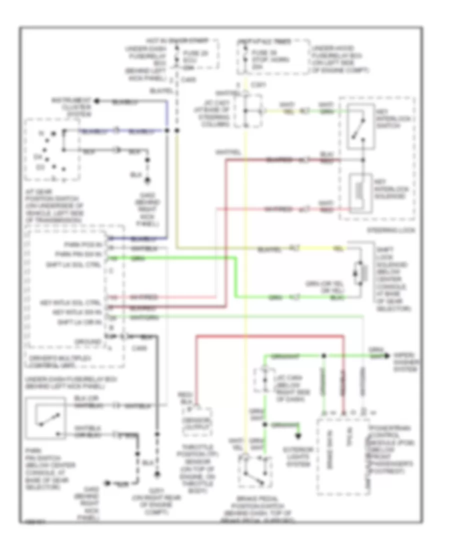 https://portal-diagnostov.com/license.html
Automotive Electricians Portal FZCO
Automotive Electricians Portal FZCO
https://portal-diagnostov.com/license.html
https://portal-diagnostov.com/license.html
Automotive Electricians Portal FZCO
Automotive Electricians Portal FZCOList of elements for Shift Interlock Wiring Diagram for Acura 3.5RL 2004:
- (on top of engine, on throttle body)
- A/t gear position switch (on underside of vehicle, left side of transmission)
- Brake pedal position switch (behind dash, top of brake pedal support)
- Brake sw in
- C301
- C405
- C406
- Driver's multiplex control unit
- Exterior lights system
- Fuse 20 ecu 20a
- Fuse 39 stop, horn 20a
- G251 (on right rear of engine compt)
- G402 (behind right kick panel)
- Ground
- Hot at all times
- Hot in on or start
- Instrument cluster system
- J/c c421 (at base of steering column)
- J/c c464 (below right side of dash)
- Key interlock solenoid
- Key interlock switch
- Key intlk sol ctrl
- Key intlk sw in
- Park pin sw in
- Park pin switch (below center console, at base of gear selector)
- Park pos in
- Powertrain control module (pcm) (below front passenger's footrest)
- Sensor output
- Shft lk cir ctrl
- Shft lk cir in
- Shft lk sol ctrl
- Shift lock solenoid (below center console, at base of gear selector)
- Steering lock
- Throttle position (tp) sensor
- Tps in
- Under-dash fuse/relay box (behind left kick panel)
- Under-hood fuse/relay box (on left side of engine compt)
- Wiper/ washer system
STARTING/CHARGING
Charging Wiring Diagram for Acura 3.5RL 2004
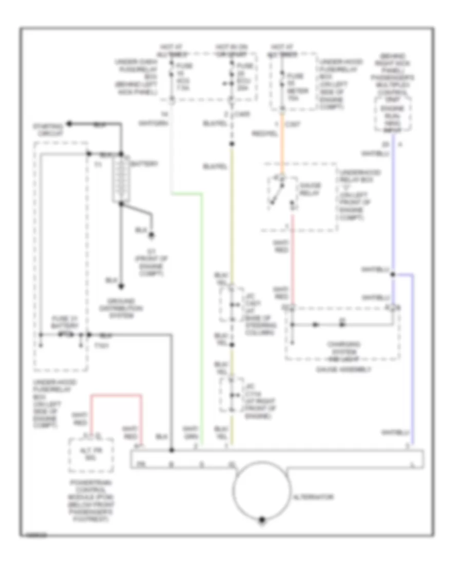 https://portal-diagnostov.com/license.html
Automotive Electricians Portal FZCO
Automotive Electricians Portal FZCO
https://portal-diagnostov.com/license.html
https://portal-diagnostov.com/license.html
Automotive Electricians Portal FZCO
Automotive Electricians Portal FZCOList of elements for Charging Wiring Diagram for Acura 3.5RL 2004:
- (behind right kick panel) passenger's multiplex control unit
- Alt. fr sig.
- Alternator
- Battery
- C307
- C405
- Charging system ind light
- Engine run- ning input
- Fuse 31 battery 120a
- Fuse acg 7.5a
- Fuse ecu 20a
- Fuse meter 15a
- G1 (front of engine compt)
- Gauge assembly
- Gauge relay
- Ground distribution system
- Hot at all times
- Hot in on or start
- J/c c114 (at right front of engine)
- J/c c421 (at base of steering column)
- Powertrain control module (pcm) (below front passenger's footrest)
- Starting circuit
- T101
- Under-dash fuse/relay box (behind left kick panel)
- Under-hood fuse/relay box (on left side of engine compt)
- Underhood relay box ``c" (on left front of engine compt)
Starting Wiring Diagram for Acura 3.5RL 2004
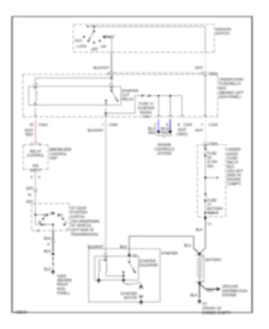 https://portal-diagnostov.com/license.html
Automotive Electricians Portal FZCO
Automotive Electricians Portal FZCO
https://portal-diagnostov.com/license.html
https://portal-diagnostov.com/license.html
Automotive Electricians Portal FZCO
Automotive Electricians Portal FZCOList of elements for Starting Wiring Diagram for Acura 3.5RL 2004:
- (not used)
- A/t gear position switch (on underside of vehicle, left side of transmission)
- Acc
- Battery
- C304
- C329
- C403
- C405
- C406
- C901
- Engine controls system
- Fuse 14 starter signal 7.5a
- Fuse battery 120a
- Fuse ig sw 50a
- G1 (front of engine compt)
- G402 (behind right kick panel)
- Ground distribution system
- Ignition switch
- Immobilizer control unit
- Lock
- On off
- P/n input
- Relay control
- Start
- Starter
- Starter cut relay
- Starter motor
- Starter solenoid
- Under- hood fuse/ relay box (on left side of engine compt)
- Under-dash fuse/relay box (behind left kick panel)
SUPPLEMENTAL RESTRAINTS
Supplemental Restraints Wiring Diagram (1 of 2) for Acura 3.5RL 2004
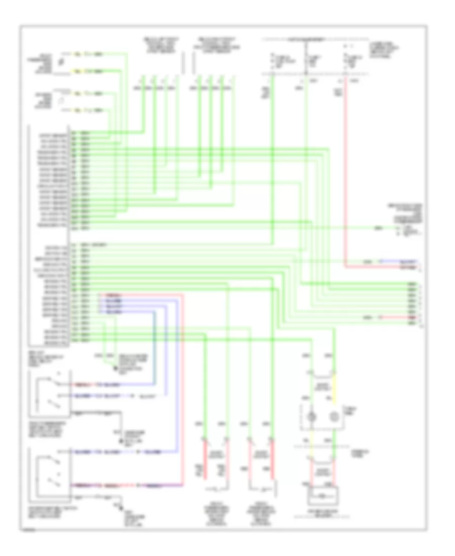 https://portal-diagnostov.com/license.html
Automotive Electricians Portal FZCO
Automotive Electricians Portal FZCO
https://portal-diagnostov.com/license.html
https://portal-diagnostov.com/license.html
Automotive Electricians Portal FZCO
Automotive Electricians Portal FZCOList of elements for Supplemental Restraints Wiring Diagram (1 of 2) for Acura 3.5RL 2004:
- (behind right side of rear seat) (usa) onstar system interface unit
- (below center console, near data link connector) g801
- (below left front door sill trim) driver's side impact sensor
- (below right front door sill trim) front passenger's side impact sensor
- A10
- A11
- A12
- A13
- A14
- A15
- A16
- A17
- A18
- Air bag ctrl
- B10
- B11
- B12
- B13
- B14
- B15
- B16
- B17
- B18
- C404
- C801
- Cable reel
- Dlc input/output
- Driver's air bag inflator
- Driver's seat belt switch (shown with seat belt unbuckled)
- Driver's side air bag inflator
- Front passenger's air bag first inflator (behind glove box)
- Front passenger's air bag second inflator (behind glove box)
- Front passenger's seat belt switch (shown with seat belt unbuckled)
- Front passenger's side air bag inflator
- Fuse 22 fuel pump 20a
- Fuse 23 srs 7.5a
- Fuse 7 srs 10a
- G651 (near base of left "b" pillar)
- Ground
- Hot in on or start
- Ignition (va)
- Ignition (vb)
- Impact sensor
- Inflator ctrl
- Mes conn input
- Opds unit input
- Red
- Seat belt sw
- Service check in
- Short contact
- Srs ind ctrl
- Srs unit (behind center of dash, below radio)
- Steering wheel
- Tensioner ctrl
- Under-dash fuse/relay box (behind left kick panel)
- Veh shock in
Supplemental Restraints Wiring Diagram (2 of 2) for Acura 3.5RL 2004
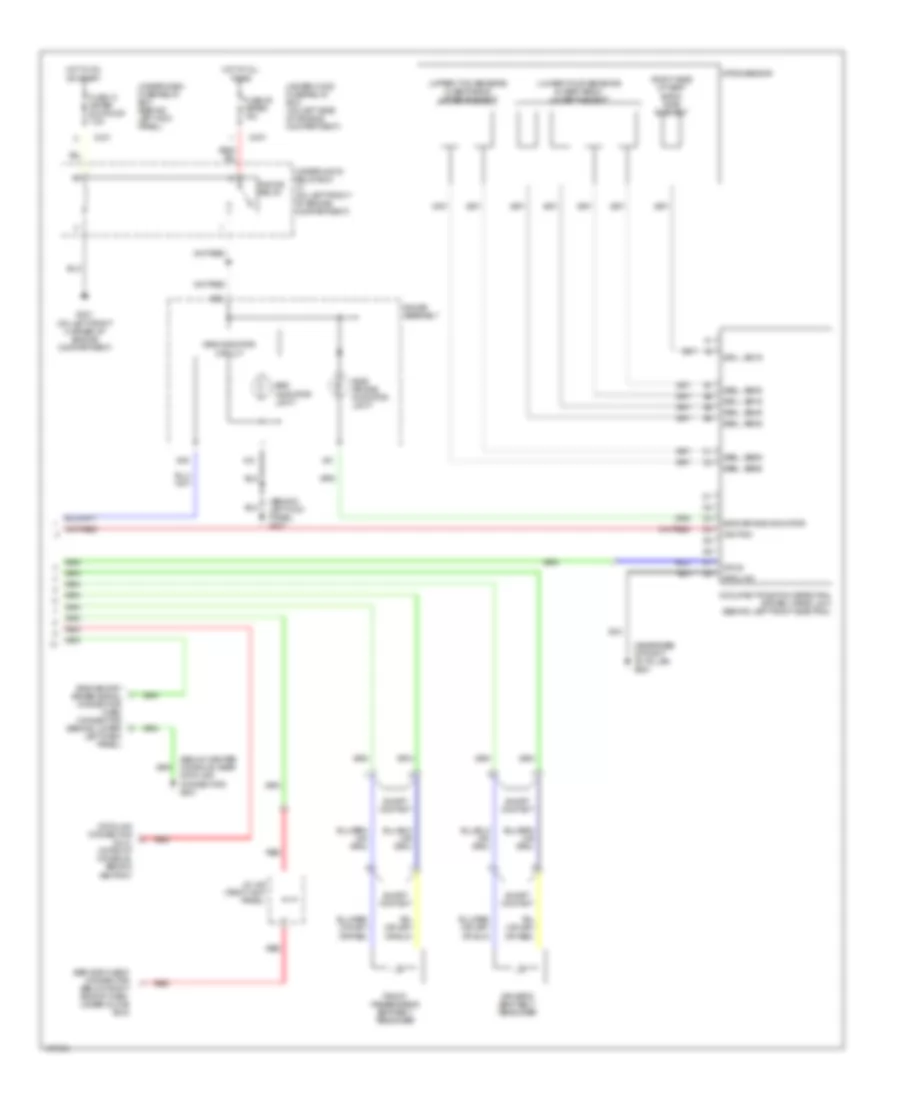 https://portal-diagnostov.com/license.html
Automotive Electricians Portal FZCO
Automotive Electricians Portal FZCO
https://portal-diagnostov.com/license.html
https://portal-diagnostov.com/license.html
Automotive Electricians Portal FZCO
Automotive Electricians Portal FZCOList of elements for Supplemental Restraints Wiring Diagram (2 of 2) for Acura 3.5RL 2004:
- (behind left kick panel) g401
- (below center console, near data link connector) g801
- (lower four sensors in seat back) lower element
- (near base of right "b" pillar) g601
- (right side of seat back) side element
- (upper two sensors in seat back) upper element
- A10
- A21
- A22
- B15
- C307
- C331
- Data link connector (dlc) (in front console, behind ashtray)
- Driver's seat belt tensioner
- Front passenger's seat belt tensioner
- Fuse 13 meter sun roof 7.5a
- Fuse 55 meter 15a
- G301 (on left front corner of engine compartment)
- Gauge assembly
- Gauge relay
- Ground
- Hot at all times
- Hot in on or start
- Ignition
- J/c 448 (right kick panel)
- Occupant position detection system (opds) unit (behind left front side trim)
- Odus
- Opds sensor
- Red
- Sb1l, sb1s
- Sb2l, sb2s
- Sb3l, sb3s
- Sb4l, sb4s
- Sb5l, sb5s
- Sb6l, sb6s
- Service check connector (below right side of dash, under glove box)
- Short contact
- Side air bag indicator
- Side air bag indicator light
- Srs indicator circuit
- Srs indicator light
- Srs memory erase signal connector (mes) connector (behind lower left dash panel)
- Ss1l, ss1s
- Under-dash fuse/relay box (behind left kick panel)
- Under-hood fuse/relay box (on left side of engine compartment)
- Under-hood relay box "c" (on left front of engine compartment)
TRANSMISSION
A/T Wiring Diagram for Acura 3.5RL 2004
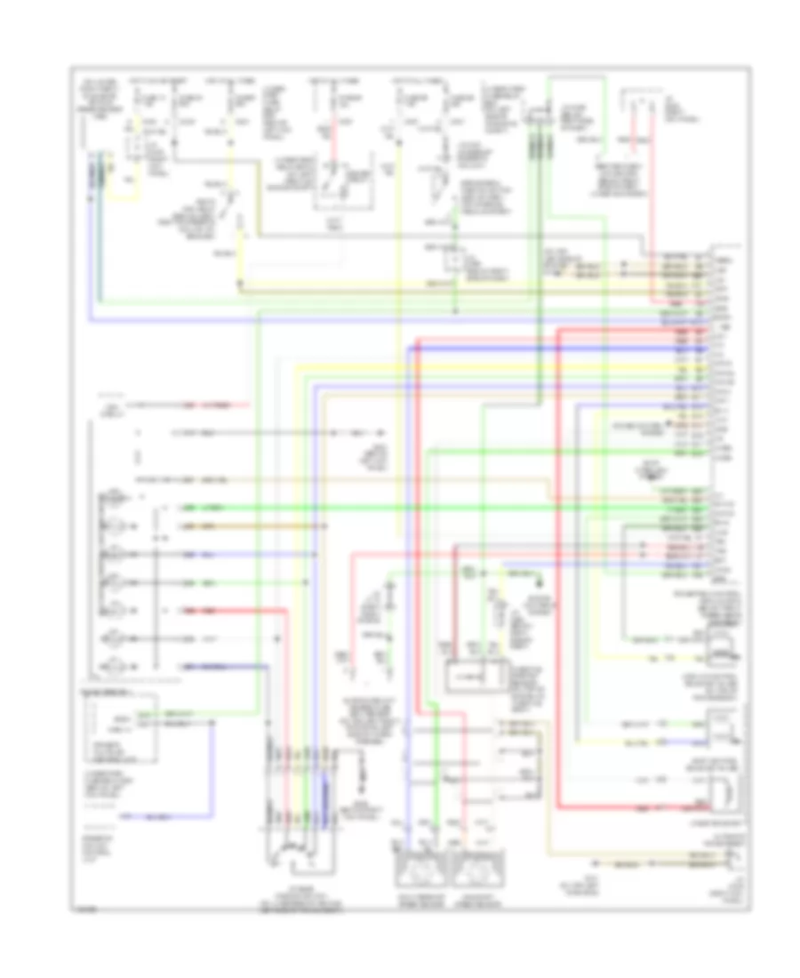 https://portal-diagnostov.com/license.html
Automotive Electricians Portal FZCO
Automotive Electricians Portal FZCO
https://portal-diagnostov.com/license.html
https://portal-diagnostov.com/license.html
Automotive Electricians Portal FZCO
Automotive Electricians Portal FZCOList of elements for A/T Wiring Diagram for Acura 3.5RL 2004:
- (on lower right front on engine) vehicle speed sensor (vss)
- (on top left side of engine) g101
- A/t & cruise control lights-on circuit
- A/t gear position switch (on underside of vehicle, left side of transmission)
- A10
- A22
- Atp 1
- Atp 2
- Atp d3
- Atp d4
- Atp pn
- Atp r
- Automatic transmission
- B12
- B23
- B24
- B25
- B26
- B27
- B28
- B29
- B30
- Bksw
- Brake pedal position switch (behind dash, top of brake pedal support)
- C301
- C307
- C404
- C405
- C501
- Countershaft speed sensor
- Crs
- Cruise control system
- D4 ind
- Driver's multiplex control unit
- Ect
- Engine controls system
- Engine coolant temperature (ect) sensor (on top left front of engine, left side of water passage)
- Fuse 13 7.5a
- Fuse 20 20a
- Fuse 39 20a
- Fuse 55 15a
- Fuse 56 7.5a
- Fuse 6 20a
- G101 (on top left of engine)
- G401 (behind left kick panel)
- G402 (behind right kick panel)
- Gauge assembly
- Gauge relay
- Hot at all times
- Hot in on or start
- Ig p1
- Ig p2
- Ilu
- J/c c114 (right front of eng)
- J/c c421 (at base of steering column)
- J/c c448 (right kick panel)
- J/c c456 (below right side of dash)
- J/c c464 (below right side of dash)
- Lc a
- Lc b
- Lg1
- Lg2
- Linear solenoid
- Lock-up control solenoid valves (on top of transmission)
- Ls +
- Ls-
- Main circuit
- Mainshaft speed sensor
- Ncsg
- Nmsg
- Park in
- Pgm-fi main relay (behind dash, right of steering column, on bracket)
- Powertrain control module (pcm) (below front passenger's footrest)
- R p
- Red
- Red (or pnk)
- Scs
- Service check connector (below right side of dash, under glove box)
- Sg2
- Sh a
- Sh b
- Shift control solenoid valves
- Shift interlock system
- Steering column control unit
- Throttle position sensor (on top of engine, on throttle body)
- Tps
- Under- dash fuse/ relay box (behind left kick panel)
- Under-dash fuse/relay box (behind left kick panel)
- Under-hood fuse/relay box (on left side of of engine compt)
- Underhood relay box c (on left front of engine compt)
- Vbsol
- Vbu
- Vcc2
- Vss
TRUNK, TAILGATE, FUEL DOOR
Trunk Release Wiring Diagram for Acura 3.5RL 2004
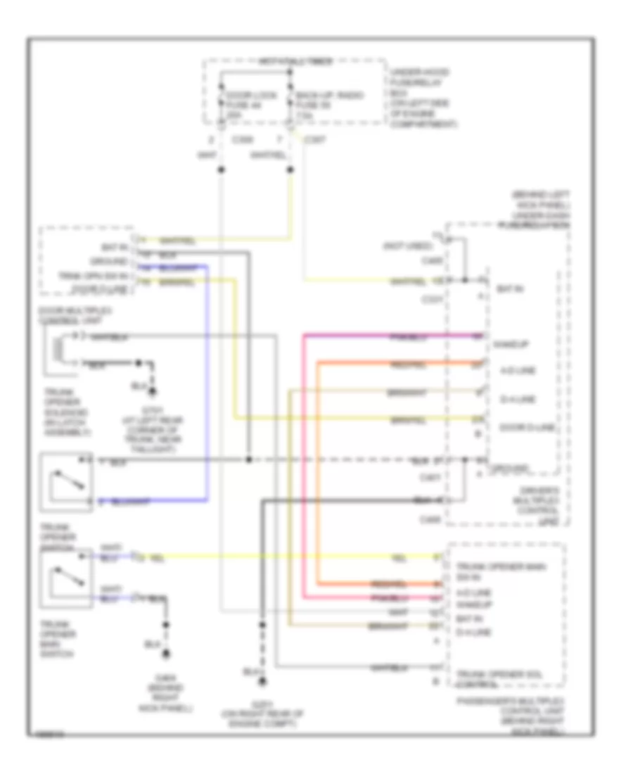 https://portal-diagnostov.com/license.html
Automotive Electricians Portal FZCO
Automotive Electricians Portal FZCO
https://portal-diagnostov.com/license.html
https://portal-diagnostov.com/license.html
Automotive Electricians Portal FZCO
Automotive Electricians Portal FZCOList of elements for Trunk Release Wiring Diagram for Acura 3.5RL 2004:
- (behind left kick panel) under-dash fuse/relay box
- (not used)
- A-d line
- Back-up, radio fuse 56 7.5a
- Bat in
- C306
- C307
- C331
- C401
- C405
- C406
- D-a line
- Door d-line
- Door lock fuse 44 20a
- Door multiplex control unit
- Driver's multiplex control unit
- G251 (on right rear of engine compt)
- G404 (behind right kick panel)
- G701 (at left rear corner of trunk, near taillight)
- Ground
- Hot at all times
- Passenger's multiplex control unit (behind right kick panel)
- Trnk opn sw in
- Trunk opener main sw in
- Trunk opener main switch
- Trunk opener sol control
- Trunk opener solenoid (in latch assembly)
- Trunk opener switch
- Under-hood fuse/relay box (on left side of engine compartment)
- Wakeup
WARNING SYSTEMS
Warning Systems Wiring Diagram for Acura 3.5RL 2004
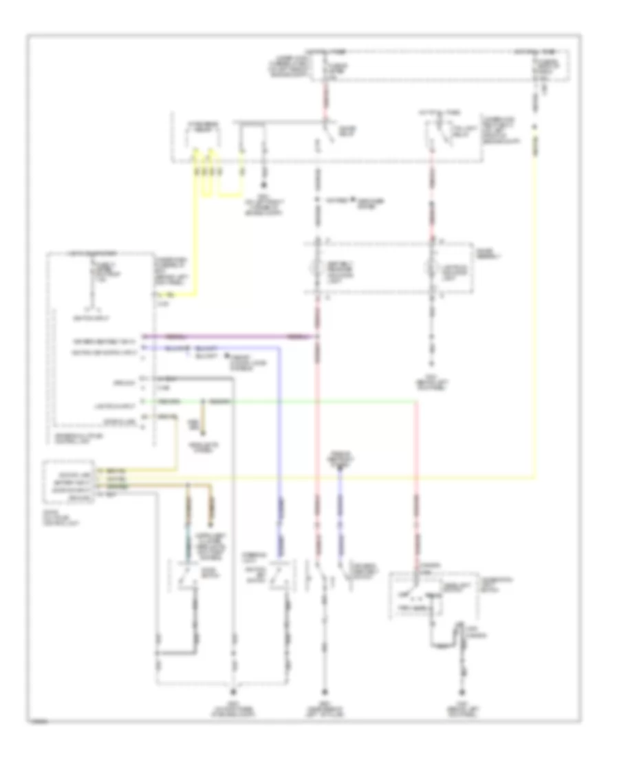 https://portal-diagnostov.com/license.html
Automotive Electricians Portal FZCO
Automotive Electricians Portal FZCO
https://portal-diagnostov.com/license.html
https://portal-diagnostov.com/license.html
Automotive Electricians Portal FZCO
Automotive Electricians Portal FZCOList of elements for Warning Systems Wiring Diagram for Acura 3.5RL 2004:
- (canada)
- (usa)
- 15a
- 7.5a
- A/t reverse relay
- Auto
- Battery input
- C307
- C331
- C406
- Combination light switch
- Defogger system
- Door d-line
- Door multiplex control unit
- Door sw input
- Door switch
- Driver's multiplex control unit
- Driver's seat belt sw in
- Driver's seat belt switch
- Fuse 13 meter, sun roof 7.5a
- Fuse 55 meter
- Fuse 56 back-up radio
- G251 (on right rear of engine compt)
- G301 (on left front corner of engine compt)
- G401 (behind left kick panel)
- G651 (near base of left ``b" pillar)
- Gauge assembly
- Gauge relay
- Ground
- Head
- Headlight switch
- Headlights system
- Hot at all times
- Hot in on or start
- Ignition input
- Ignition key switch
- Ignition key switch input
- Instrument cluster, headlights, anti-theft systems
- Lights on input
- Lights-on indicator light
- Memory & door locks systems
- Off
- Park
- Passive restraint system
- Seat belt reminder indicator light
- Steering lock
- Taillight relay
- Under-dash fuse/relay box (behind left kick panel)
- Under-hood fuse/relay box (on left side of engine compt)
- Underhood relay box c (on left front of engine compt)
WIPER/WASHER
Wiper/Washer Wiring Diagram for Acura 3.5RL 2004
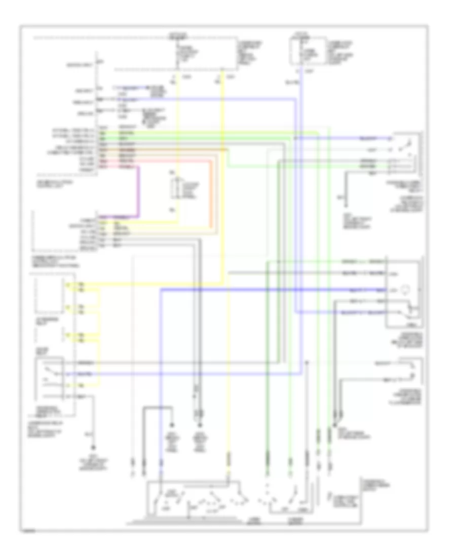 https://portal-diagnostov.com/license.html
Automotive Electricians Portal FZCO
Automotive Electricians Portal FZCO
https://portal-diagnostov.com/license.html
https://portal-diagnostov.com/license.html
Automotive Electricians Portal FZCO
Automotive Electricians Portal FZCOList of elements for Wiper/Washer Wiring Diagram for Acura 3.5RL 2004:
- A-d line
- A/t reverse relay
- A10
- A13
- A14
- A22
- B10
- B18
- B19
- B20
- B22
- C307
- C330
- C331
- C402
- C404
- C406
- Cruise control system
- D-a line
- Driver's multiplex control unit
- G251
- G301 (on left front corner of engine compt)
- G302 (on left rear of engine compt)
- G401 (behind left kick panel)
- G402 (behind right kick panel)
- Gauge relay
- Ground
- High
- Hot at all times
- Hot in on or start
- Ignition input
- Int
- Int dwell time ctrl in
- Int wiper on in
- Intermittent dwell time controller
- Intermittent wiper ctrl
- J/c c448 (right kick panel)
- Low
- Meter, sun roof fuse 13 7.5a
- Mist
- Mist switch
- Off
- Park
- Park input
- Passenger's multiplex control unit (behind right kick panel)
- Run
- Under-dash fuse/relay box (behind left kick panel)
- Under-hood fuse/relay box (on left side of engine compt)
- Underhood relay box a (on left front of engine compt)
- Underhood relay box c (on left front of engine compt)
- Vss input
- Wakeup
- Wash
- Washer switch
- Windshield washer motor (in washer fluid reservoir)
- Windshield wiper intermittent relay
- Windshield wiper motor (below left side of air scoop)
- Windshield wiper motor relay
- Windshield wiper/washer switch
- Wiper fuse 58 30a
- Wiper switch
- Wshld washer on in

 Čeština
 Dansk
Dansk Deutsch
 Ελληνικά
 English
 English
 Español
 Suomi
Suomi Français
 Français
 עברית
עברית Hrvatski
 Magyar
 Italiano
 日本語
日本語 한국어
한국어 Nederlands
 Polski
 Português
 Português
 Română
 Русский
 Slovenčina
 Slovenščina
 Svenska
 中文 (中国)
