AIR CONDITIONING
Automatic A/C Wiring Diagram (1 of 3) for Acura TL Type S 2007
 https://portal-diagnostov.com/license.html
Automotive Electricians Portal FZCO
Automotive Electricians Portal FZCO
https://portal-diagnostov.com/license.html
https://portal-diagnostov.com/license.html
Automotive Electricians Portal FZCO
Automotive Electricians Portal FZCO
List of elements for Automatic A/C Wiring Diagram (1 of 3) for Acura TL Type S 2007:
- (b: on steering column) (c: on steering wheel) cable reel
- (behind right side of front bumper) a/c pressure switch
- (below left side of dash) driver's mode control motor
- (canada)
- (under middle of dash)
- (under middle of dash) junction connector c512
- A1 ig2
- A10 air mix potential
- A11 cpm ig2
- A11 remote sw gnd
- A12 cpm tx
- A13 fr def
- A14 a/c pressure sw
- A15 in-car temp sens
- A16 outside temp sens
- A17 sunlight sens
- A18 temp sens
- A19 fresh
- A2 cpm rx
- A20 air mix potential
- A5 sens common gnd
- A6 ground
- A7 blower feedback
- A8 pwr transistor ctrl
- Amd-p
- Audio unit
- B1 driver's mode vent
- B10 driver's mode 3
- B11 driver's mode 1
- B12 driver's mode 2
- B13 mode 3, 4
- B14 passenger's mode 2
- B15 passenger's mode 1
- B16 air mix potential
- B18
- B2 driver's mode def
- B3 air mix hot
- B4 air mix cool
- B5 mode vent
- B6 mode def
- B7 air mix hot
- B8 air mix cool
- B9 driver's mode 4
- Back switch
- C10
- C18
- Climate control unit (behind glove box)
- Control block
- Cpm ground
- D16
- Driver's air mix control motor (below left side of dash)
- Evaporator temperature sensor (under right side of dash)
- Front passenger's air mix control motor (under right side of dash)
- Front passenger's mode control motor (behind glove box)
- Frs
- Fuse 7.5a
- G302 (behind left side of front bumper)
- G503
- Ground
- Hfl-voice control switch
- Hot at all times
- Hot in on
- Ig2
- In-car temperature sensor (on dash, right of steering column)
- Junction connector c506 (left side of dash)
- M-cool
- M-def
- M-heat
- M-hot
- M-vent
- Mode 1
- Mode 1, 4
- Mode 2
- Mode 3
- Mode 3, 6
- Mode 5
- N20
- Outside air temperature sensor (behind middle of front bumper)
- Pgm-fi main relay 1
- Pnk
- Rec
- Recirculate
- Recirculation control motor (behind glove box)
- Red
- Relay control module
- S-com
- S5v
- Sound systems
- Steering wheel
- Sunlight sensor (right side of dash)
- Talk switch
- Under-dash fuse/relay box (behind left end of dash)
- Under-hood fuse/relay box (left rear of engine compt)
- W/ navigation
- X35
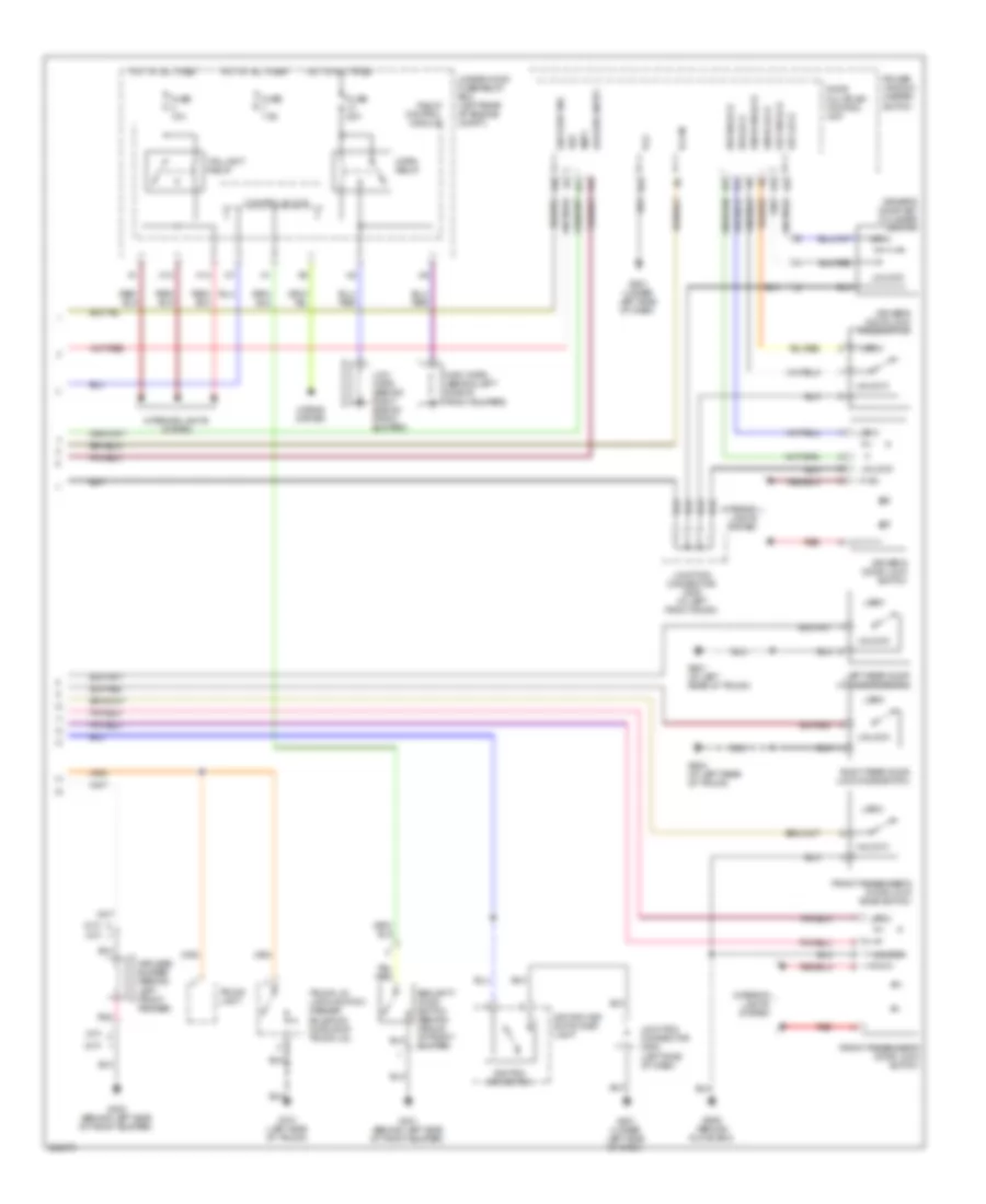
Automatic A/C Wiring Diagram (2 of 3) for Acura TL Type S 2007
 https://portal-diagnostov.com/license.html
Automotive Electricians Portal FZCO
Automotive Electricians Portal FZCO
https://portal-diagnostov.com/license.html
https://portal-diagnostov.com/license.html
Automotive Electricians Portal FZCO
Automotive Electricians Portal FZCOList of elements for Automatic A/C Wiring Diagram (2 of 3) for Acura TL Type S 2007:
- (behind left end of dash) under-dash fuse/relay box
- (left side of engine) ect sensor 1
- (under middle of dash)
- 30a
- A/c
- A/c compressor
- A/c compressor clutch
- A/c compressor clutch relay
- A/c condenser fan motor (behind right side of radiator)
- A/c condenser fan relay
- A/c diode b (under left side of dash)
- A13
- A14
- A14 (ect1) input
- A2 ground
- A22
- A3 ground
- B-can
- B10 fan ctrl
- B11
- B24 (ect2) input
- Blower motor (under right side of dash)
- Blower motor relay
- Blower power transistor (behind right side of dash, left of blower motor)
- Body controller area network transceiver
- C12 gnd (sg2)
- Cpu/fail safe circuit/can controller
- D11
- D15
- Diode a
- E1 gnd (sg4)
- E10
- E14
- E15
- E15 (canh)
- E26 (canl)
- E27 rly ctrl
- E5 rly ctrl
- E6 fan ctrl
- Ecm/pcm (behind center of dash)
- Ect sensor 2 (under front of engine compt)
- F10
- F14
- F15
- F17
- F19
- Fan control relay (right side of engine compt)
- Fast controller area network transceiver
- Fuse
- Fuse 40a
- Fuse 7.5a
- G101 (left side of engine)
- G201 (behind right side of front bumper)
- G301 (behind left side of front bumper)
- G302 (behind left side of front bumper)
- G506 (behind glove box)
- Gauge control module
- Hot at all times
- J/c c508 (left side of dash)
- Junction connector c512
- Micu
- N22
- N28
- Pnk
- Radiator fan motor (under front of engine compt)
- Radiator fan relay
- Red
- S1 (ther- mal joint) (right side of engine)
- Under-dash fuse/relay box (behind left end of dash)
- Under-hood fuse/relay box (left rear of engine compt)
- X11
Automatic A/C Wiring Diagram (3 of 3) for Acura TL Type S 2007
 https://portal-diagnostov.com/license.html
Automotive Electricians Portal FZCO
Automotive Electricians Portal FZCO
https://portal-diagnostov.com/license.html
https://portal-diagnostov.com/license.html
Automotive Electricians Portal FZCO
Automotive Electricians Portal FZCOList of elements for Automatic A/C Wiring Diagram (3 of 3) for Acura TL Type S 2007:
- (left side of dash) junction connector c508
- (right c-pillar) junction connector c603
- (under middle of dash) g503
- (under middle of dash) junction connector c510
- A/c
- A/c rx
- A/c tx
- A10
- A11
- A12
- A13
- A14
- A15
- A16
- A17
- A18
- A19
- A20
- A21
- A22
- Acc
- Audio bus sh
- Audio bus+
- Audio bus-
- Audio-hvac sub display unit
- Auto
- B sig
- B-can
- B10
- B13
- B14
- Bus+
- Bus-
- C sig
- C10
- Ce (load)
- Compass 1
- Compass 2
- Compass 3
- Compass 4
- D10
- D11
- D12
- D13
- D14
- D15
- D16
- Defogger ind front
- Defogger on ind rear window
- Display panel control unit
- Driver's climate control switch assembly
- Dual
- Dual ind
- E10
- E11
- E12
- E13
- E14
- E15
- E16
- E17
- E18
- E19
- E20
- E21
- E22
- Ecu bus sh
- Ecu bus+
- Ecu bus-
- Fr def
- Fr def ind
- Front passenger's climate control switch assembly
- Front window defogger sw rear window
- Fuse 32 7.5a
- G sig
- G501 (under left side of dash)
- Gnd
- Hot in acc or on
- Ig2
- Ill(-) bulb
- Ill(-) led
- Ill+
- Ill-
- Ims0
- Ims1
- Ind +
- Ind-dual
- Inh
- Instrument cluster system
- Interior lights system
- Lcd bl(+)
- Lcd bl(-)
- Mic
- Mic+ hands free control unit (front of roof)
- Microphone
- Mode
- N36
- Navigation system
- Navigation unit (if equipped) (in trunk, below left side of package tray)
- Off
- Pnk
- R sig
- Rec ind
- Recirculation ind
- Red
- Roof console
- Rr def
- Rr def ind
- Sd +b
- Sh gnd
- Shld
- Sig gnd
- Sig sh
- Sig+
- Sound systems
- Strg
- Sw defogger
- Under-dash fuse/relay box (behind left end of dash)
- W/ navigation
ANTI-LOCK BRAKES
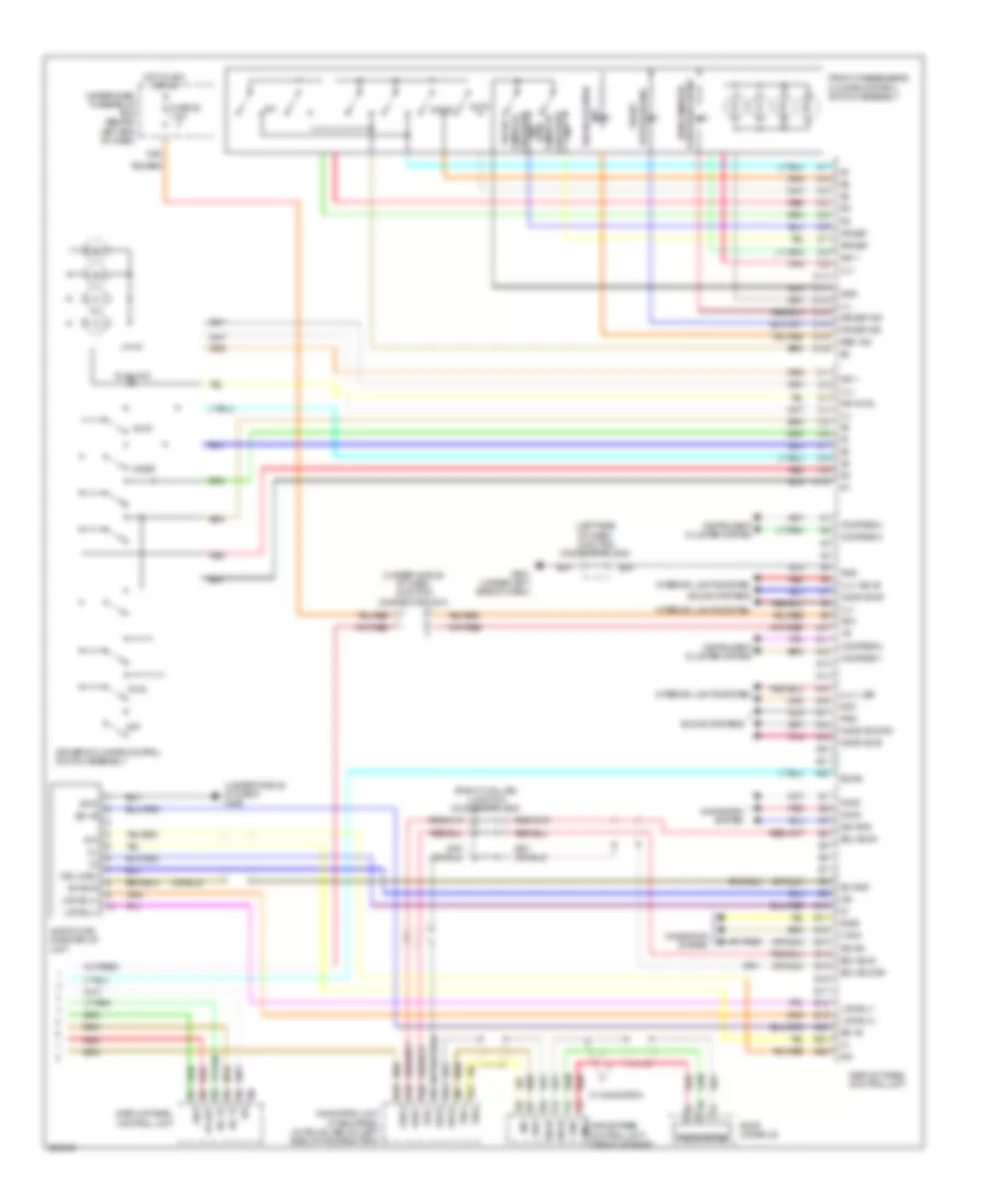
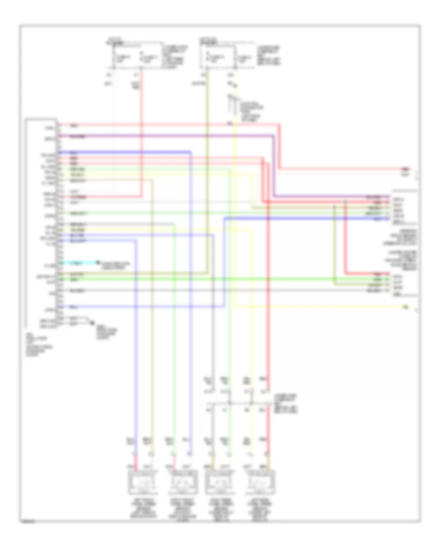
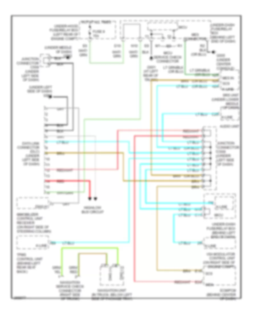
Anti-lock Brakes Wiring Diagram (1 of 2) for Acura TL Type S 2007
 https://portal-diagnostov.com/license.html
Automotive Electricians Portal FZCO
Automotive Electricians Portal FZCO
https://portal-diagnostov.com/license.html
https://portal-diagnostov.com/license.html
Automotive Electricians Portal FZCO
Automotive Electricians Portal FZCOList of elements for Anti-lock Brakes Wiring Diagram (1 of 2) for Acura TL Type S 2007:
- (under center console) yaw rate-lateral acceleration sensor
- C10
- C12
- Can-h
- Can-l
- Computer data lines system
- E12
- Fl +b
- Fl -gnd
- Fr +b
- Fr -gnd
- Fsr +b
- Fuse 17 30a
- Fuse 18 15a
- Fuse 18 40a
- Fuse 21 7.5a
- G203 (right side of engine compt)
- Glat
- Ground
- Hot at all times
- Hot in on or start
- Ignition in
- Junction connector c506 (left side of dash)
- K-line
- Left front wheel speed sensor (left side of engine compt)
- Left rear wheel speed sensor (under left rear of vehicle)
- Mr +b
- Pnk
- Red
- Right front wheel speed sensor (on right side of engine compt)
- Right rear wheel speed sensor (under right rear of vehicle)
- Rl +b
- Rl -gnd
- Rr +b
- Rr -gnd
- Sgnd
- Steering angle sensor (on side of steering column)
- Str-a
- Str-b
- Str-d
- Svcc
- Under-dash fuse/relay box (behind left end of dash)
- Under-hood fuse/relay box (left rear of engine compt)
- Vsa modulator unit (on right side of engine compt)
- X34
- Yaw
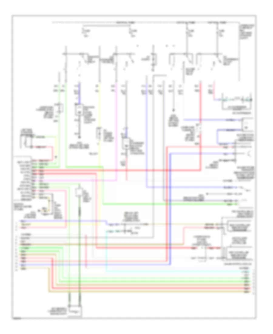
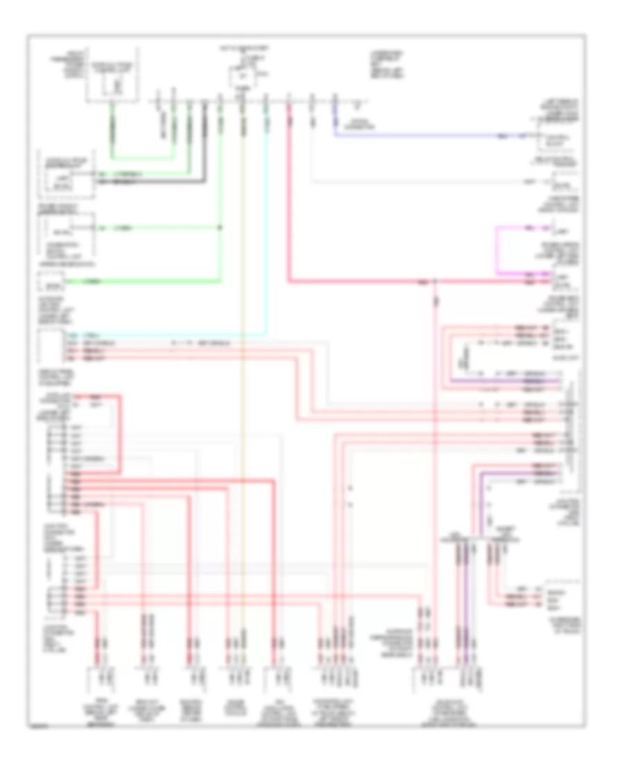
Anti-lock Brakes Wiring Diagram (2 of 2) for Acura TL Type S 2007
 https://portal-diagnostov.com/license.html
Automotive Electricians Portal FZCO
Automotive Electricians Portal FZCO
https://portal-diagnostov.com/license.html
https://portal-diagnostov.com/license.html
Automotive Electricians Portal FZCO
Automotive Electricians Portal FZCOList of elements for Anti-lock Brakes Wiring Diagram (2 of 2) for Acura TL Type S 2007:
- (bksw) e8
- (under middle of dash) junction connector c512
- A13
- A14
- Abs ind
- B18
- Brake fluid level switch (integral to brake fluid reservoir cap)
- Brake pedal position switch (near brake pedal)
- Brake system ind
- Computer data lines system
- Cpu/fail safe circuit/can controller
- Drive circuit
- Ecm/pcm (behind center of dash)
- Fast controller area network transceiver
- Fuse 13 20a
- G302 (behind left side of front bumper)
- G501 (under left side of dash)
- Gauge control module
- Hot at all times
- Immobilizer control unit-receiver (on right side of steering column)
- Interior lights system
- Junction connector c507 (left side of dash)
- N30
- N34
- Parking brake switch (under center console)
- Red
- Sw input
- Under-dash fuse/relay box (behind left end of dash)
- Under-hood fuse/relay box (left rear of engine compt)
- Vsa activation ind
- Vsa off switch
- Vsa system ind
- Warning drive circuit
ANTI-THEFT
Forced Entry Wiring Diagram (1 of 2) for Acura TL Type S 2007
 https://portal-diagnostov.com/license.html
Automotive Electricians Portal FZCO
Automotive Electricians Portal FZCO
https://portal-diagnostov.com/license.html
https://portal-diagnostov.com/license.html
Automotive Electricians Portal FZCO
Automotive Electricians Portal FZCOList of elements for Forced Entry Wiring Diagram (1 of 2) for Acura TL Type S 2007:
- (not used)
- +b door lock
- A20
- Antenna
- Audio unit
- B-can
- D/l lock
- D/l unlock
- D11
- Dr d/l unlock
- Driver's door lock actuator (rear of left front door)
- Driver's door switch (at left "b" pillar)
- Drswas
- Drswdr
- Drswra
- Drswrd
- E10
- E14
- E15
- Front passenger's door lock actuator (rear of right front door)
- Front passenger's door switch (at right "b" pillar)
- Fuse 20a
- Fuse 30a
- Fuse 7.5a
- G501 (under left side of dash)
- G504 (under middle of dash)
- G601 (at left rear of trunk)
- Gnd
- H10
- H12
- H13
- Hot at all times
- Hot in on or start
- Ig key sw
- Ig1
- J/c c507 (left side of dash)
- J/c c508 (left side of dash)
- J10
- Junction connector c506 (left side of dash)
- Junction connector c635 (in left front door)
- K11
- K12
- Keyless buzzer
- Keyless receiver unit (under left side of dash)
- Left rear door lock actuator (rear of left rear door)
- Left rear door switch (at left "c" pillar)
- Micu
- N15
- P13
- P24
- P25
- Q14
- Radio sw
- Rem as lock
- Rem as unlock
- Right rear door lock actuator (rear of right rear door)
- Right rear door switch (at right "c" pillar)
- Security
- Security indicator
- Sig out
- Sil as unlock
- Sil ra unlock
- Sil rd unlock
- Trunk switch
- Under-dash fuse/relay box (behind left end of dash)
- Vbu
- X24
- X34
Forced Entry Wiring Diagram (2 of 2) for Acura TL Type S 2007
 https://portal-diagnostov.com/license.html
Automotive Electricians Portal FZCO
Automotive Electricians Portal FZCO
https://portal-diagnostov.com/license.html
https://portal-diagnostov.com/license.html
Automotive Electricians Portal FZCO
Automotive Electricians Portal FZCOList of elements for Forced Entry Wiring Diagram (2 of 2) for Acura TL Type S 2007:
- (a/t)
- (m/t)
- A10
- A14
- A15
- A16
- A18
- A19
- B-can
- B11
- B14
- Control block
- Door multiplex control unit
- Driver's door key cylinder switch
- Driver's door lock knob switch
- Driver's door lock switch
- Front passenger's door lock knob switch
- Front passenger's door lock switch
- Fuse 10a
- Fuse 20a
- Fuse 7.5a
- G301 (behind left side of front bumper)
- G302 (behind left side of front bumper)
- G501 (under left side of dash)
- G506 (behind glove box)
- G601 (at left rear of trunk)
- G602 (at left rear of trunk)
- G701 (left side of trunk)
- H13
- H14
- High horn (behind left side of front bumper)
- Horn relay
- Horns system
- Hot at all times
- Ignition key switch
- Ignition key switch/key light
- Interior lights system
- Junction connector c508 (left side of dash)
- Junction connector c635 (in left front door)
- Key lock
- Key unlock
- Keyless buzzer (behind left front fender)
- Keyless entry
- Knob lock
- Knob unlock
- Left rear door lock knob switch
- Lock
- Low horn (behind right side of front bumper)
- Pg1
- Pnk
- Power window master switch
- Red
- Relay control module
- Right rear door lock knob switch
- Security hood switch (behind middle of front bumper)
- Security ind
- Sw lock
- Sw unlock
- Taillight relay
- Trunk lid latch switch/ opener solenoid (middle of trunk lid)
- Trunk light
- Under-hood fuse/relay box (left rear of engine compt)
- Unlock
- Vbu
- Vmp1
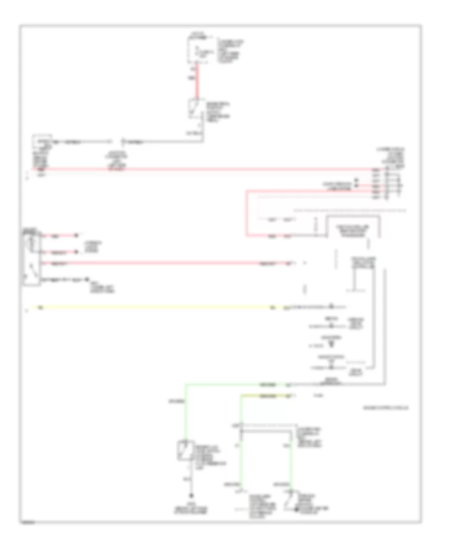
Immobilizer Wiring Diagram for Acura TL Type S 2007
 https://portal-diagnostov.com/license.html
Automotive Electricians Portal FZCO
Automotive Electricians Portal FZCO
https://portal-diagnostov.com/license.html
https://portal-diagnostov.com/license.html
Automotive Electricians Portal FZCO
Automotive Electricians Portal FZCOList of elements for Immobilizer Wiring Diagram for Acura TL Type S 2007:
- B15
- B17
- Cpu/fail safe circuit/can controller
- Diag-h
- Dlc (under left side of dash)
- E13
- E20
- E25
- Ecm/pcm (behind center of dash)
- Except type s
- Fp+
- Fp-
- Fpc
- Fpcd
- Fuel pump
- Fuel pump control module (left side of trunk)
- Fuel pump ctrl
- Fuel tank unit (middle front of trunk)
- Fuse 15a
- Fuse 7.5a
- G101 (left side of engine)
- G501 (under left side of dash)
- G603 (middle front of trunk)
- Gauge control module
- Gnd
- H/brake sw
- Hot at all times
- Hot in on or start
- Ig key sw
- Ig1
- Ign in
- Ignition key switch
- Ignition key switch/ key light
- Immobilizer control unit receiver (on right side of steering column)
- Immobilizer system ind
- Imo code in
- Imoarm
- Imoes unit (canada)
- Junction connector c508 (left side of dash)
- Junction connector c510 (under middle of dash)
- Key sw
- Lg 1
- Lg1
- Micu
- N30
- N34
- P13
- Parking brake switch (under center console)
- Pgm-fi main relay 1
- Pgm-fi main relay 2
- Pnk
- Power in
- Red
- Rly ctrl
- S-net
- Type s
- Under-dash fuse/relay box (behind left end of dash)
- Vbu
- X31
- X35
- X38
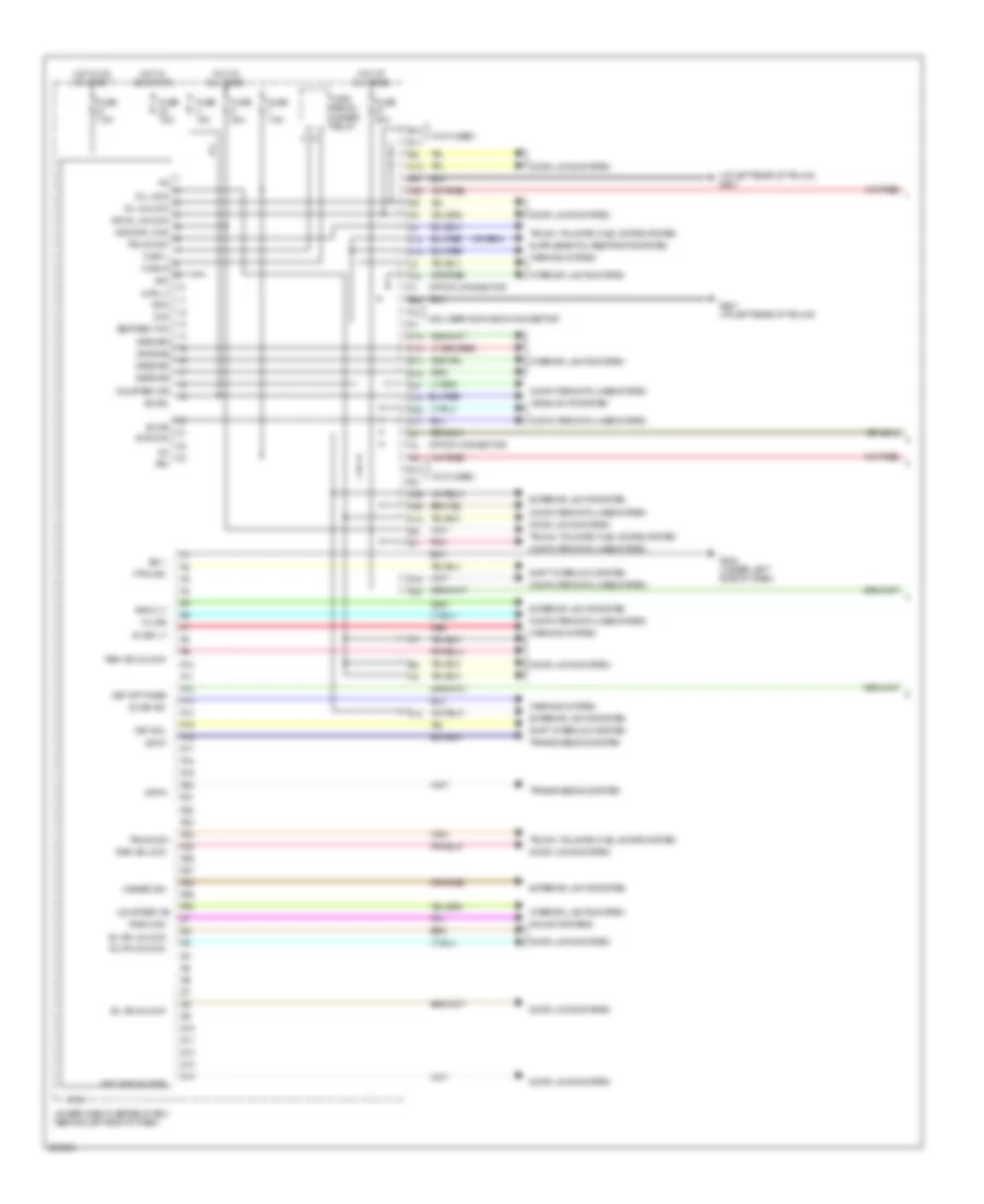
BODY CONTROL MODULES
Body Control Modules Wiring Diagram (1 of 2) for Acura TL Type S 2007
 https://portal-diagnostov.com/license.html
Automotive Electricians Portal FZCO
Automotive Electricians Portal FZCO
https://portal-diagnostov.com/license.html
https://portal-diagnostov.com/license.html
Automotive Electricians Portal FZCO
Automotive Electricians Portal FZCOList of elements for Body Control Modules Wiring Diagram (1 of 2) for Acura TL Type S 2007:
- (at left rear of trunk) g601
- (not used)
- +b drl
- Atp-p
- Atp-r
- B-can
- Back lt
- Chk
- Computer data lines system
- Courtesy as
- Courtesy dr
- D11
- D12
- D14
- Door locks system
- Drswas
- Drswdr
- Drswra
- Drswrd
- E10
- E14
- E15
- Exterior lights system
- F12
- F14
- Fuse 15a
- Fuse 20a
- Fuse 30a
- Fuse 7.5a
- G502 (under left side of dash)
- G601 (at left rear of trunk)
- H10
- H12
- H13
- H14
- Hazard sw
- Headlights system
- Hot at all times
- Hot in acc or on
- Hot in on or start
- Ig key lt
- Ig key sw
- Ig1 vbu
- Interior lights system
- K-line
- K11
- K12
- Key off timer
- Key sol
- Keyless buzzer
- Micu
- Micu service check connector
- N22
- N26
- N28
- Option connector
- P pin sw
- P10
- P11
- P12
- P13
- P14
- P15
- P16
- P17
- P18
- P19
- P20
- P21
- P22
- P23
- P24
- P25
- P26
- P27
- P28
- P29
- P30
- Pg d/l lock d/l unlock dr d/l unlock +b door lock trunk act turn l turn r acc intr lt
- Pnk
- Q10
- Q11
- Q12
- Q13
- Q14
- Radio sw
- Red
- Rem as lock
- Rem as unlock
- Seat belt sw
- Sg-1
- Sg-2
- Shift interlock system
- Sil as unlock
- Sil ra unlock
- Sil rd unlock
- Sound systems
- Stop sw
- Transmissions system
- Trunk sw
- Trunk, tailgate, fuel doors system
- Turn signal/ hazard relay
- Under-dash fuse/relay box (behind left end of dash)
- Warning system
- X18
- X24
- X27
- X35
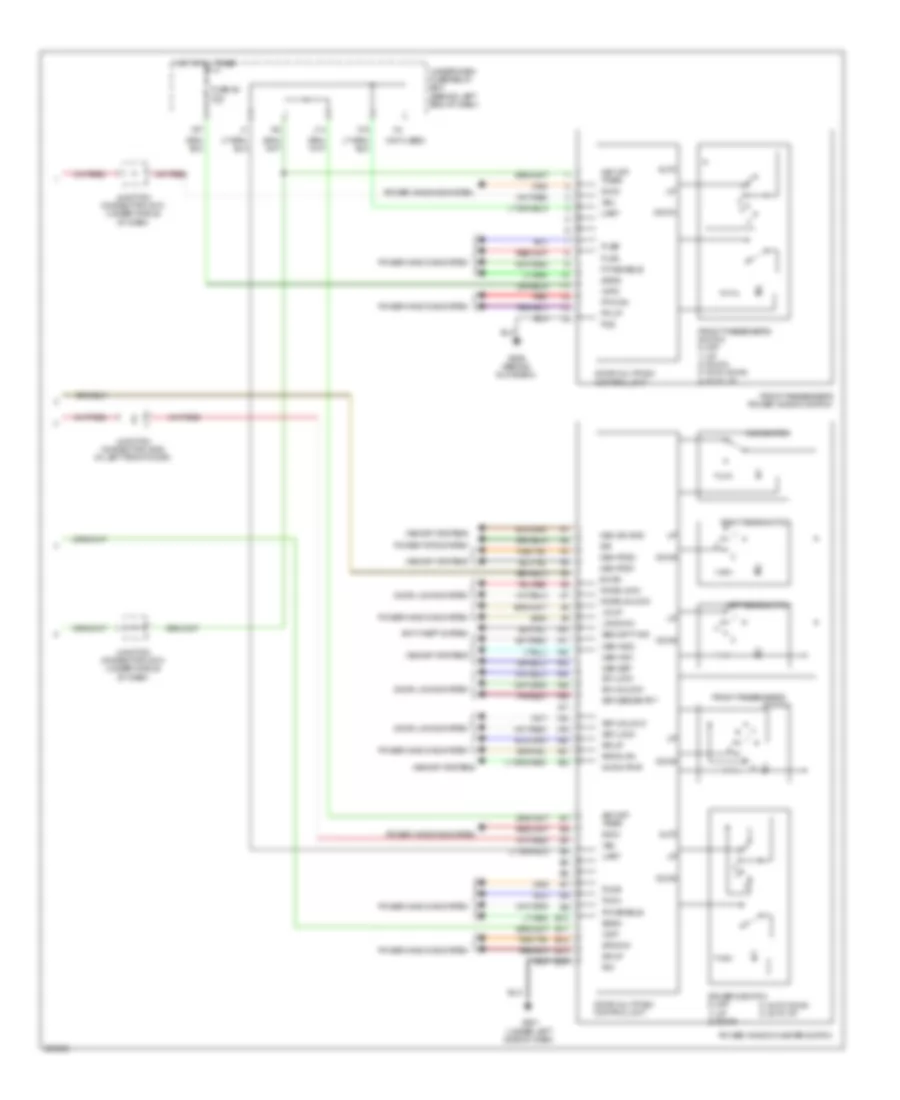
Body Control Modules Wiring Diagram (2 of 2) for Acura TL Type S 2007
 https://portal-diagnostov.com/license.html
Automotive Electricians Portal FZCO
Automotive Electricians Portal FZCO
https://portal-diagnostov.com/license.html
https://portal-diagnostov.com/license.html
Automotive Electricians Portal FZCO
Automotive Electricians Portal FZCOList of elements for Body Control Modules Wiring Diagram (2 of 2) for Acura TL Type S 2007:
- (not used)
- 3) auto down 4) auto up
- A10
- A11
- A12
- A13
- A14
- A15
- A16
- A17
- A18
- A19
- A20
- A21
- A22
- Anti-theft system
- Auto
- B-can
- Door locks system
- Door multiplex control unit
- Down
- Dr dwn
- Dr up
- Driver's switch 0) off 1) up 2) down
- Fp dwn
- Fr up
- Front passenger's
- Front passenger's power window switch
- Front passenger's switch 0) off 1) up 2) down 3) auto down 4) auto up
- Fuse 26 30a
- G501 (under left side of dash)
- G506 (behind glove box)
- Hot at all times
- J14
- Junction connector c510 (under middle of dash)
- Junction connector c635 (in left front door)
- Key lock
- Key off timer
- Key unlock
- Keyless entry
- Knob lock
- Knob unlock
- Left rear switch
- Lr down
- Lr up
- Main switch
- Mem ind1
- Mem ind2
- Mem pos1
- Mem pos2
- Mem set
- Mem sw gnd
- Memory systems
- Mm sw pwr
- P/w enable
- Pg1
- Pg2
- Pls a
- Pls b
- Plsa
- Plsb
- Power tops system
- Power window master switch
- Power windows system
- Red
- Right rear switch
- Rr down
- Rr up
- S/r
- Security ind
- Sgnd
- Svcc
- Sw lock
- Sw unlock
- Switch
- Uart
- Under-dash fuse/relay box (behind left end of dash)
- Vbu
- Vmp1
- Vmp2
- X15
- X37
COMPUTER DATA LINES
Data Link Connector Wiring Diagram for Acura TL Type S 2007
 https://portal-diagnostov.com/license.html
Automotive Electricians Portal FZCO
Automotive Electricians Portal FZCO
https://portal-diagnostov.com/license.html
https://portal-diagnostov.com/license.html
Automotive Electricians Portal FZCO
Automotive Electricians Portal FZCOList of elements for Data Link Connector Wiring Diagram for Acura TL Type S 2007:
- (under left side of dash) g501
- (under middle of dash) g503
- A24
- A25
- A26
- Audio unit
- C11
- C25
- D10
- Data link connector (dlc) (under left side of dash)
- Diag (+)
- Diag (-)
- Diag-h
- E16
- E24
- Ecm/pcm (behind center of dash)
- Fuse 8 15a
- G505 (under center console)
- G601 (at left rear of trunk)
- High/low bus circuit
- Hot at all times
- Immobilizer control unit receiver (on right side of steering column)
- Junction connector c509 (under left side of dash)
- K-line
- Mes connector
- Mes in
- Micu
- Micu service check connector
- N10
- N13
- Navigation service check connector (right side of trunk)
- Navigation unit (in truck, below left side of package tray)
- Red
- Scs
- Srs unit (under lower middle of dash)
- Tpms control unit (behind left rear seat back)
- Under-dash fuse/relay box (behind left end of dash)
- Under-hood fuse/relay box (left rear of engine compt)
- Vsa modulator control unit (on right side of engine compt)
- Wen
High/Low Bus Wiring Diagram for Acura TL Type S 2007
 https://portal-diagnostov.com/license.html
Automotive Electricians Portal FZCO
Automotive Electricians Portal FZCO
https://portal-diagnostov.com/license.html
https://portal-diagnostov.com/license.html
Automotive Electricians Portal FZCO
Automotive Electricians Portal FZCOList of elements for High/Low Bus Wiring Diagram for Acura TL Type S 2007:
- (left rear of engine compt) under-hood fuse/relay box
- (not used)
- A10
- A13
- A14
- A16
- A17
- A18
- A20
- A21
- A22
- Acuralink control unit (xm receiver) (usa: navigation) (right side of trunk)
- Aucralink reprogramming connector (on right red rear shelf)
- Audio unit
- Automatic lighting control unit (under left side of dash)
- B-can
- B10
- B11
- B19
- Bus (+)
- Bus (-)
- Bus +
- Bus -
- Bus sh
- Can-h
- Can-l
- Combination switch control unit
- Control block
- D11
- Data link connector (dlc) (under left side of dash)
- Display panel control unit (if equipped)
- Door multiplex control unit
- E14
- E15
- E26
- Ecm/pcm (behind center of dash)
- Except usa: navigation
- Front passenger's power window switch
- Fuse 21 7.5a
- Gauge control module
- Hands free control unit (front of roof)
- Hot in on or start
- Ig1
- Junction connector c512 (under middle of dash)
- Junction connector c603 (right c-pillar)
- Micu
- N22
- N28
- Navigation unit (if equipped) (in trunk, below left side of package tray)
- Option connector
- Pnk
- Power mirror control unit (under left side of dash)
- Power seat control unit (under driver's seat)
- Power window master switch
- Red
- Relay control module
- Srs unit (under lower middle of dash)
- Tpms control unit (behind left rear seat back)
- Uart
- Under-dash fuse/relay box (behind left end of dash)
- Usa: navigation
- Vsa modulator control unit (on right side of engine compt)
- Wiper/washer switch
- X15
- X18
- X27
- Xm receiver (right side of trunk)
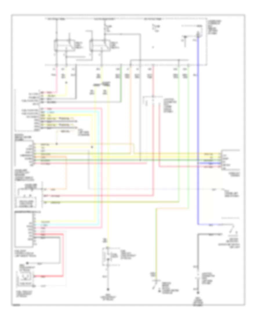
COOLING FAN
Cooling Fan Wiring Diagram for Acura TL Type S 2007
 https://portal-diagnostov.com/license.html
Automotive Electricians Portal FZCO
Automotive Electricians Portal FZCO
https://portal-diagnostov.com/license.html
https://portal-diagnostov.com/license.html
Automotive Electricians Portal FZCO
Automotive Electricians Portal FZCOList of elements for Cooling Fan Wiring Diagram for Acura TL Type S 2007:
- (behind left side of front bumper) g302
- (canh) communication line (high)
- (canl) communication line (low)
- (ect1) sensor
- (ect2) sensor
- (sg2) sensor ground
- (sg4) sensor ground
- A/c condenser fan motor (behind right side of radiator)
- A/c condenser fan relay
- A/c diode a
- A/c diode b (under left side of dash)
- A/c pressure switch
- A/c pressure switch (behind right side of front bumper)
- A13
- A14
- A22
- B-can
- B10 (fanh) high fan ctrl
- B11
- B24
- Body controller area network transceiver
- C12
- Climate control unit (behind glove box)
- Control block
- Cpu/fail safe circuit/can controller
- D11
- D15
- D16
- E10
- E14
- E15
- E26
- E5 (mrly) relay ctrl
- E6 (fanl) low fan ctrl
- Ecm/pcm (behind center of dash)
- Ect sensor 1 (left side of engine)
- Ect sensor 2 (under front of engine compt)
- F14
- F15
- F17
- F19
- Fan control relay (right side of engine compt)
- Fast controller area network transceiver
- Fuse 23 7.5a
- Fuse 30a
- Fuse 7.5a
- G201 (behind right side of front bumper)
- G301 (behind left side of front bumper)
- Gauge control module
- Hot at all times
- Hot in on
- Input
- J/c c508 (left side of dash)
- Junction connector c512 (under middle of dash)
- Micu
- Pgm-fi main relay 1
- Pnk
- Radiator fan motor (under front of engine compt)
- Radiator fan relay
- Red
- Relay control module
- Under-dash fuse/relay box (behind left end of dash)
- Under-hood fuse/relay box (left rear of engine compt)
- X1 pnk
- X11
CRUISE CONTROL
Cruise Control Wiring Diagram for Acura TL Type S 2007
 https://portal-diagnostov.com/license.html
Automotive Electricians Portal FZCO
Automotive Electricians Portal FZCO
https://portal-diagnostov.com/license.html
https://portal-diagnostov.com/license.html
Automotive Electricians Portal FZCO
Automotive Electricians Portal FZCOList of elements for Cruise Control Wiring Diagram for Acura TL Type S 2007:
- (left side of dash) junction connector c507
- (thermal joint) s2
- (under left side of dash) g501
- (under middle of dash) junction connector c512
- A/t
- A13
- A14
- A25
- A26
- A28
- A29
- A30
- B10
- B15
- B17
- B19
- Brake pedal position switch (near brake pedal)
- C11
- C12
- C13
- C14
- C19
- Cable reel (b: on steering column) (c: on steering wheel)
- Cancel switch
- Canh high sig
- Canl low sig
- Clutch pedal position switch (m/t) (near clutch pedal)
- Control block
- Control dimming circuit a/t gear position/cruise
- Cpu/fail safe circuit/can controller
- Cruise control combination switch
- Cruise control indicator
- Cruise control main switch indicator
- Drive circuit
- Drive input
- E15
- E26
- E30
- Ecm/pcm (behind center of dash)
- Etcsrly
- Fuse 1 15a
- Fuse 13 20a
- Fuse 18 15a
- Fuse 7 7.5a
- G101 (left side of engine)
- G501 (under left side of dash)
- G503 (under middle of dash)
- Gauge control module
- Gauges/ indicators
- Ground
- Ground distribution system
- Horn relay
- Horns system
- Hot at all times
- Hot in on or start
- Interior lights system
- J/c c104 (middle of engine)
- Junction connector c507 (left side of dash)
- Junction connector c508 (left side of dash)
- Junction connector c510 (under middle of dash)
- M/t
- Main switch
- Mrly
- N29
- Network transceiver fast controller area
- Output shaft (countershaft) speed sensor (in transmission housing)
- Pgm-fi main relay 1
- Pnk
- Red
- Relay control module
- Resume switch
- S2 (thermal joint)
- Sedf
- Sefd
- Sensor input
- Set switch
- Steering wheel
- Sw input
- Switch input
- Throttle actuator control module (behind glove box)
- Throttle actuator control module relay (behind glove box)
- Tp sensor/throttle actuator (on throttle body)
- Tpsa
- Tpsb
- Transmission range switch (a/t) (on transaxle)
- Type s
- Under-dash fuse/relay box (behind left end of dash)
- Under-hood fuse/relay box (left rear of engine compt)
- Vcc
- X23
- X35
DEFOGGERS
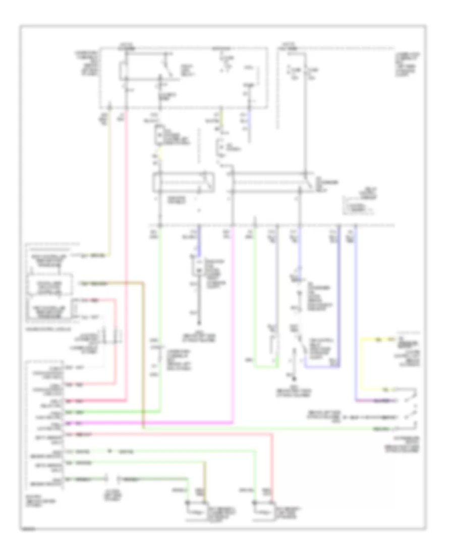
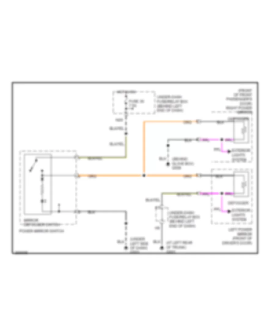
Heated Mirrors Wiring Diagram for Acura TL Type S 2007
 https://portal-diagnostov.com/license.html
Automotive Electricians Portal FZCO
Automotive Electricians Portal FZCO
https://portal-diagnostov.com/license.html
https://portal-diagnostov.com/license.html
Automotive Electricians Portal FZCO
Automotive Electricians Portal FZCOList of elements for Heated Mirrors Wiring Diagram for Acura TL Type S 2007:
- (at left rear of trunk) g601
- (behind glove box) g506
- (front of front passenger's door) right power mirror
- (under left side of dash) g501
- Defogger
- Exterior lights system
- Fuse 30 7.5a
- Hot in on
- Left power mirror (front of driver's door)
- Mirror defogger switch
- N20
- Power mirror switch
- Under-dash fuse/relay box (behind left end of dash)
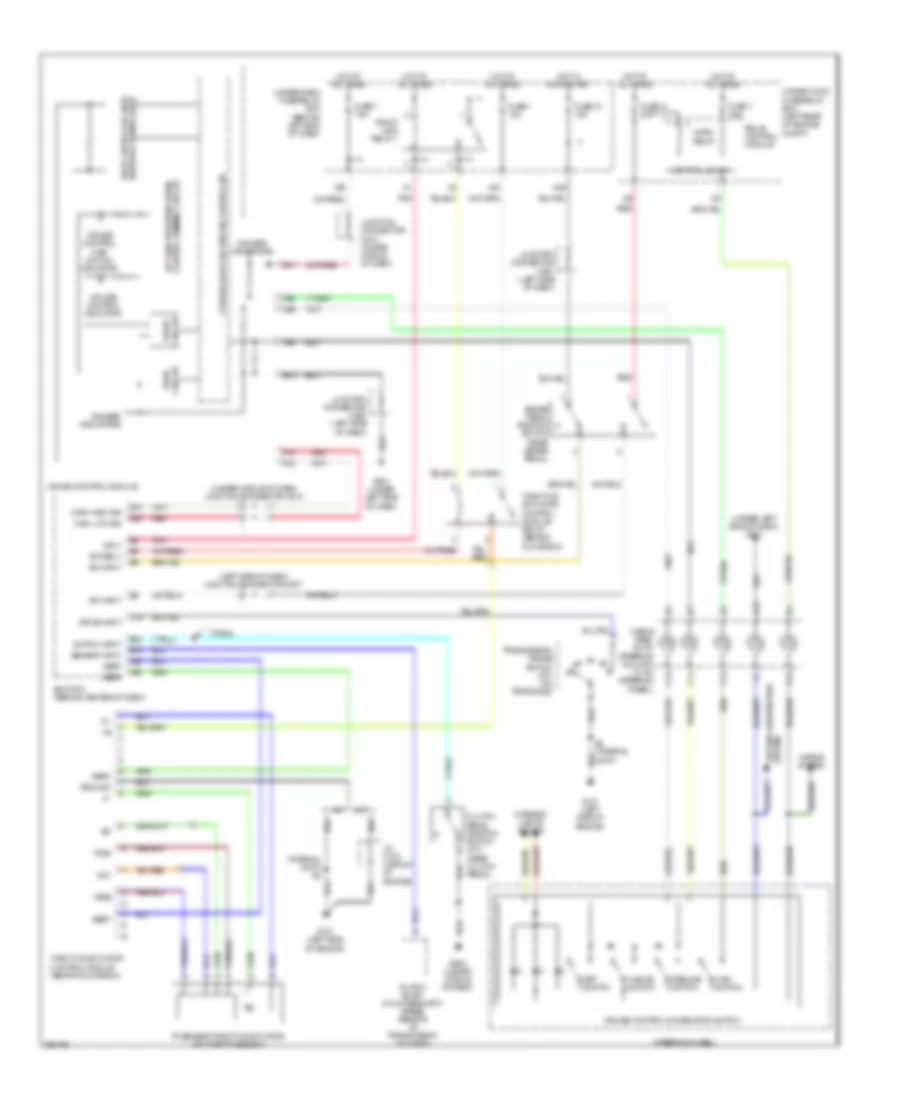
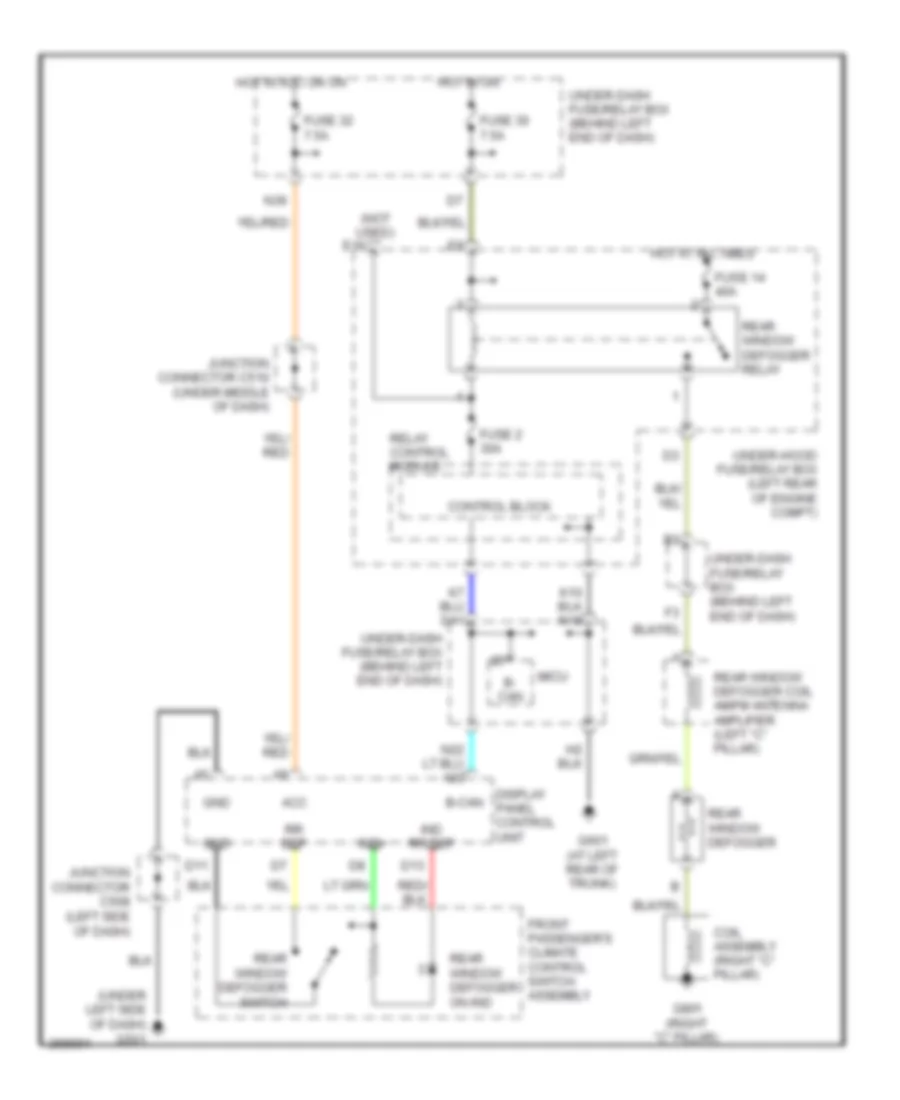
Rear Defogger Wiring Diagram for Acura TL Type S 2007
 https://portal-diagnostov.com/license.html
Automotive Electricians Portal FZCO
Automotive Electricians Portal FZCO
https://portal-diagnostov.com/license.html
https://portal-diagnostov.com/license.html
Automotive Electricians Portal FZCO
Automotive Electricians Portal FZCOList of elements for Rear Defogger Wiring Diagram for Acura TL Type S 2007:
- (not used)
- (under left side of dash) g501
- Acc
- B- can
- B-can
- Coil assembly (right "c" pillar)
- Control block
- D11
- D13
- Display panel control unit
- E16
- Front passenger's climate control switch assembly
- Fuse 14 40a
- Fuse 2 30a
- Fuse 30 7.5a
- Fuse 32 7.5a
- G601 (at left rear of trunk)
- G801 (right "c" pillar)
- Gnd
- Hot at all times
- Hot in acc or on
- Hot in on
- Ind rr def
- Ind+
- Junction connector c508 (left side of dash)
- Junction connector c510 (under middle of dash)
- Micu
- N36
- Rear window defogger
- Rear window defogger coil am/fm antenna amplifier (left "c" pillar)
- Rear window defogger on ind
- Rear window defogger relay
- Rear window defogger switch
- Relay control module
- Rr def
- Under-dash fuse/relay box (behind left end of dash)
- Under-hood fuse/relay box (left rear of engine compt)
ENGINE PERFORMANCE
3.2L
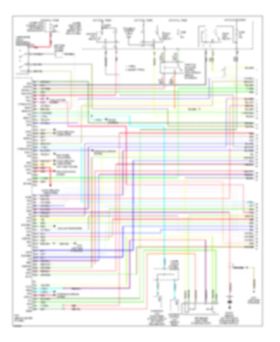
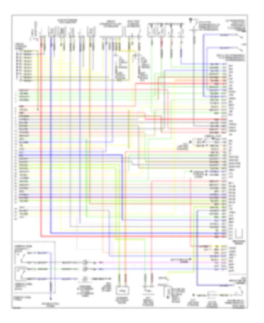
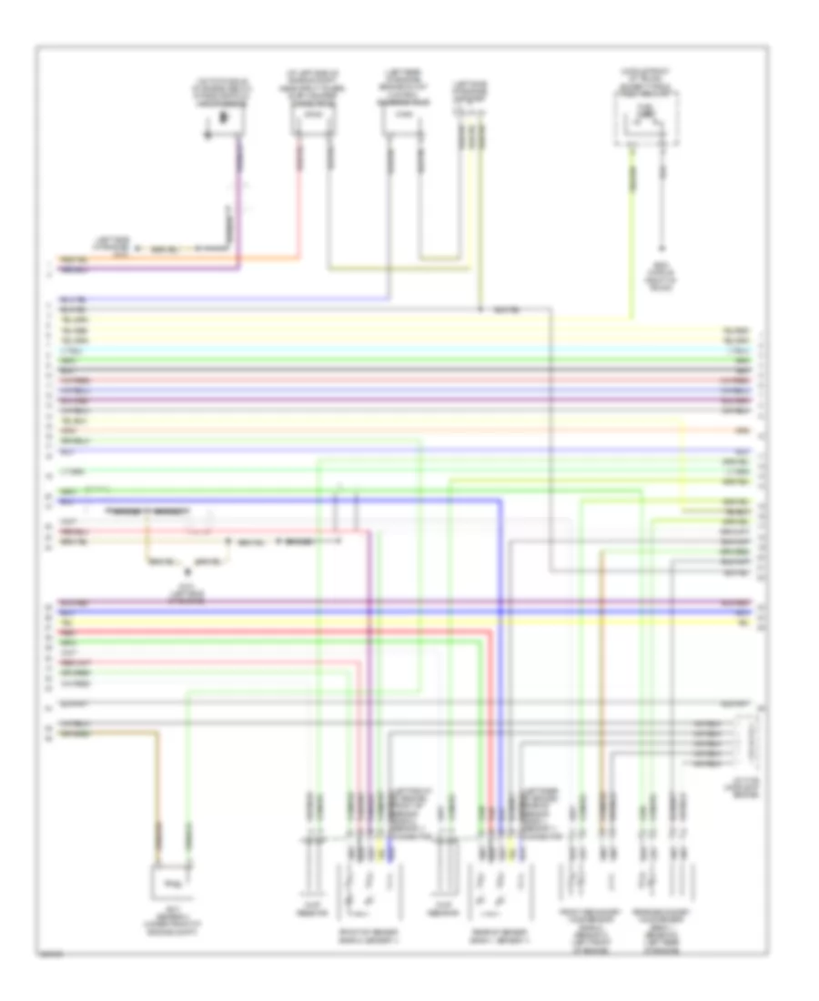
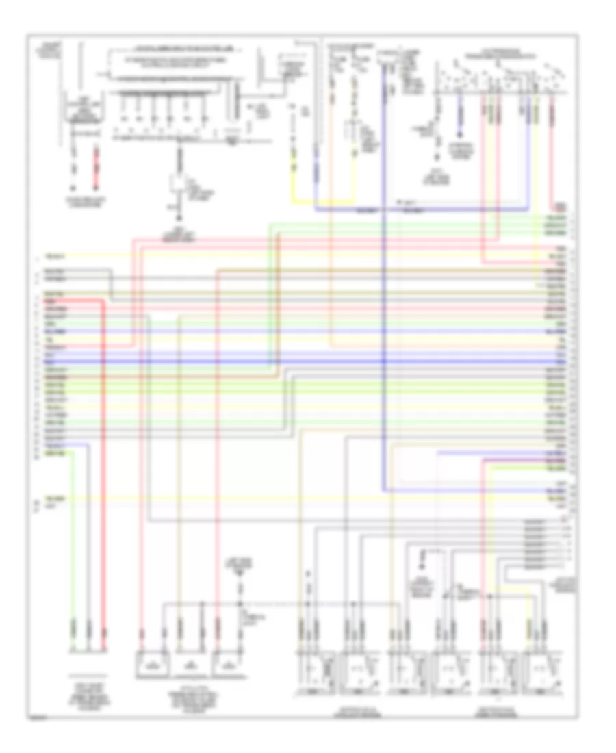
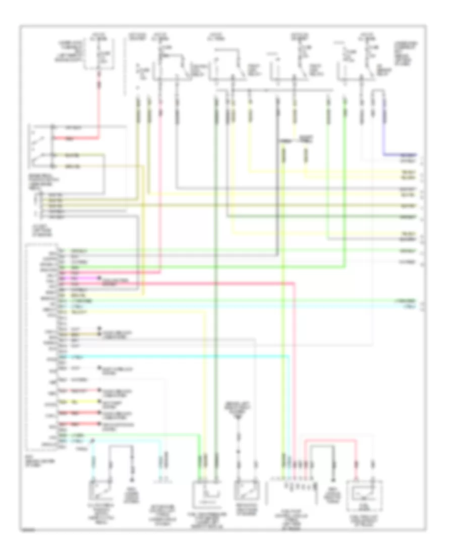
3.2L, Engine Performance Wiring Diagram, A/T (1 of 5) for Acura TL Type S 2007
 https://portal-diagnostov.com/license.html
Automotive Electricians Portal FZCO
Automotive Electricians Portal FZCO
https://portal-diagnostov.com/license.html
https://portal-diagnostov.com/license.html
Automotive Electricians Portal FZCO
Automotive Electricians Portal FZCOList of elements for 3.2L, Engine Performance Wiring Diagram, A/T (1 of 5) for Acura TL Type S 2007:
- (left side of dash) j/c c507
- (near brake pedal) brake pedal position switch
- (type s)
- (under middle of dash) j/c c512
- Acc
- Afshtcr
- Air conditioning system
- Anti-theft system
- App sensor (right side of engine compt)
- Apsa
- Apsb
- Atpn
- B10
- B11
- B12
- B13
- B14
- B15
- B16
- B17
- B18
- B19
- B20
- B21
- B22
- B23
- B24
- Bksw
- Bkswnc
- Braided
- Canh
- Canl
- Ckpa
- Ckpb
- Cmp
- Computer data lines system
- Cooling fans system
- E10
- E11
- E12
- E13
- E14
- E15
- E16
- E17
- E18
- E19
- E20
- E21
- E22
- E23
- E24
- E25
- E26
- E27
- E28
- E29
- E30
- E31
- Ect2
- Egr
- Eld
- Etcsrly
- Except type s
- Fanh
- Fanl
- Fpc
- Fpcd
- Ftp
- Fuse 15a
- Fuse 2 15a
- Fuse 20a
- G101 (left side of engine)
- Hot at all times
- Hot in on or start
- Ig1
- Ignition coil relay
- Imocd
- Imofpr
- Imt+
- Imt-
- Imtm
- Ipb1
- Ipb2
- Knock sensor (on top middle of engine, below intake manifold)
- Lg2
- Mcs
- Moonroof control unit (rear of roof)
- Mrly
- Navigation unit (if equipped) (in trunk, below left side of package tray)
- Pcm (behind center of dash)
- Pcs
- Pgm-fi main relay 1
- Pgm-fi main relay 2
- Pnk
- Pspsw
- Red
- Scs
- Sdn
- Sg3
- Sg4
- Shift inter- lock system
- Sho2sb1
- Sho2sb2
- Sls
- Smode
- Sound systems
- Starting/charging system
- Strld
- Strly
- Sts
- Sup
- Throttle actuator control module relay (behind glove box)
- To fuse 23 (diagram 3 of 5)
- Type s
- Under- dash fuse/ relay box (behind left end of dash)
- Under-hood fuse/relay box (left rear of engine compt)
- Vcc3
- Vcc4
- Vcentb1
- Vcentb2
- Vsb1
- Vsb2
- Vsp
- Vssout
- Vsv
- Wen
- X23
- X31
- X32
- X38
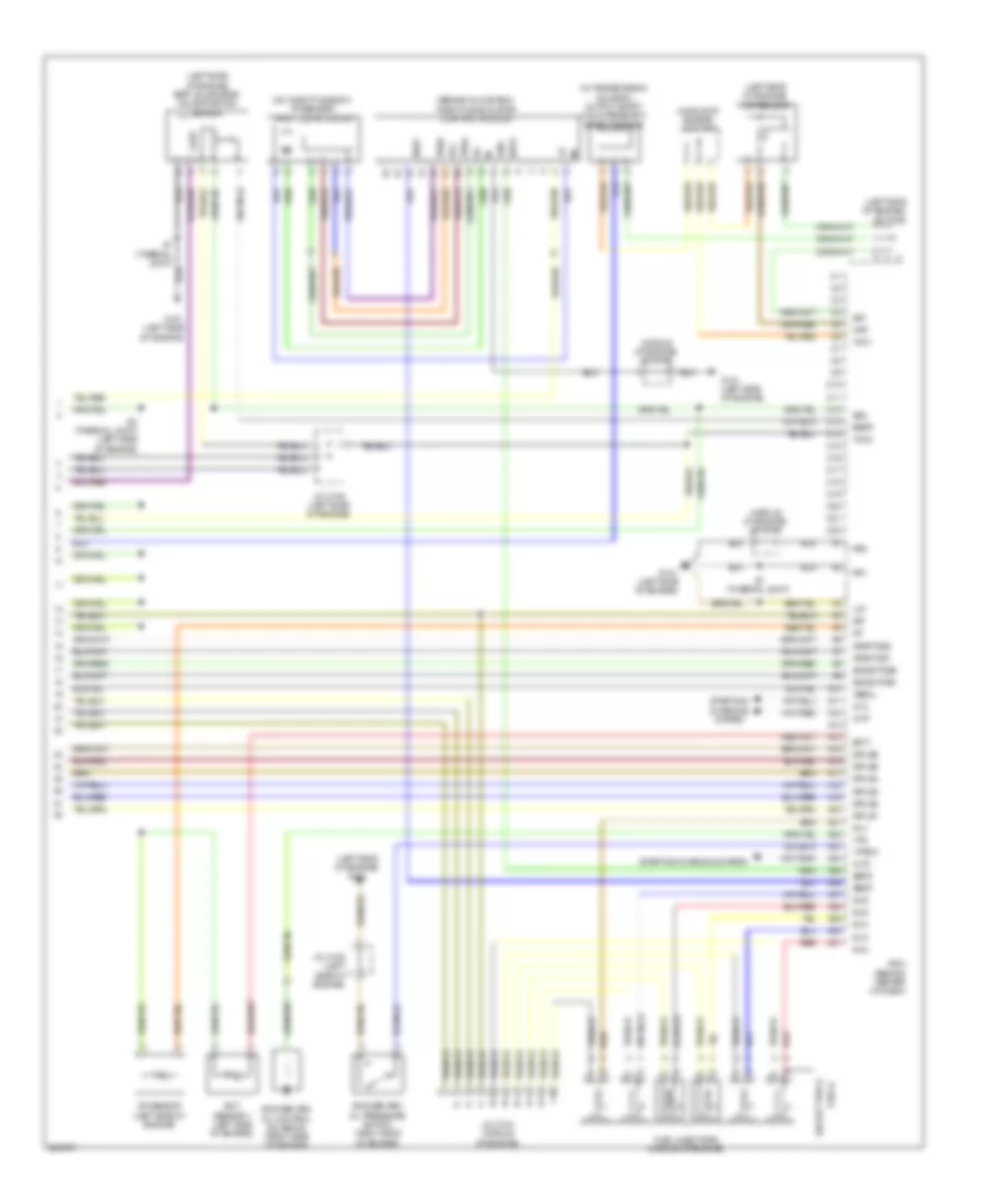
3.2L, Engine Performance Wiring Diagram, A/T (2 of 5) for Acura TL Type S 2007
 https://portal-diagnostov.com/license.html
Automotive Electricians Portal FZCO
Automotive Electricians Portal FZCO
https://portal-diagnostov.com/license.html
https://portal-diagnostov.com/license.html
Automotive Electricians Portal FZCO
Automotive Electricians Portal FZCOList of elements for 3.2L, Engine Performance Wiring Diagram, A/T (2 of 5) for Acura TL Type S 2007:
- (at left side of engine compt, near strut tower) evap canister purge valve
- (left rear of engine) engine mount control solenoid valve
- (left side of dash) j/c c508
- (left side of engine)
- (left side of engine) j/c c105
- (middle front of trunk) fuel tank unit
- (right side of engine) psp switch
- (under left rear of vehicle) fuel tank pressure (ftp) sensor
- Atf temperature sensor
- E16
- Ect sensor 2 (under front of engine compt)
- Except type s
- Fuel gauge sending unit
- Fuel pump
- G101 (left side of engine)
- G302 (behind left side of front bumper)
- G503 (under middle of dash)
- G603 (middle front of trunk)
- Imt actuator (right side of engine)
- Instrument cluster system
- J/c c105
- J/c c105 (left side of engine)
- J/c c106 (middle of engine)
- Map sensor (left side of engine)
- Output shaft (countershaft) speed sensor (in transmission housing)
- Pg2
- Pnk
- Red
- Sedf
- Sefd
- Sequential sportshift a/t shift switch
- Sequential sportshift mode switch
- Throttle actuator control module (behind glove box)
- Tp sensor/ throttle actuator (on throttle body)
- Tpsa
- Tpsb
- Transmission gear selection switch/ park pin switch/ a/t gear position indicator panel light (under center console)
- Type s
- Under-dash fuse/relay box (behind left end of dash) x5
- Vcc
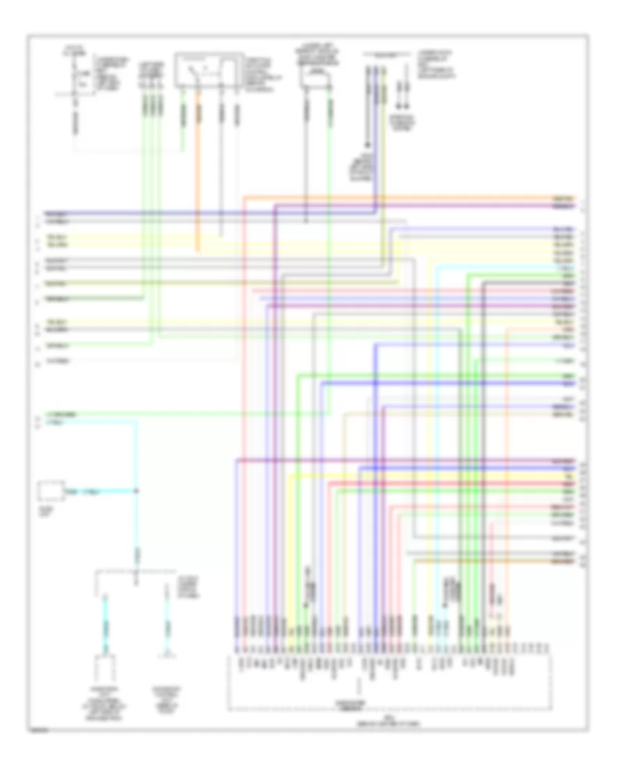
3.2L, Engine Performance Wiring Diagram, A/T (3 of 5) for Acura TL Type S 2007
 https://portal-diagnostov.com/license.html
Automotive Electricians Portal FZCO
Automotive Electricians Portal FZCO
https://portal-diagnostov.com/license.html
https://portal-diagnostov.com/license.html
Automotive Electricians Portal FZCO
Automotive Electricians Portal FZCOList of elements for 3.2L, Engine Performance Wiring Diagram, A/T (3 of 5) for Acura TL Type S 2007:
- (b1, s1) connector
- (left front of engine) front a/f sensor (b2, s1) connector
- (left rear of engine compt) under-hood fuse/relay box
- (left side of engine) egr valve & egr valve position sensor
- (under left rear of vehicle) evap canister vent shut valve
- A/f sensor relay
- Braided
- Chip resistor
- D13
- Eld unit
- Fp+
- Fp-
- Fpc
- Fpcd
- From pgm fi main relay 1 (diagram 1 of 5)
- Front a/f sensor (b2, s1)
- Front secondary ho2s sensor (b2, s2) (left front of engine)
- Fuel pump control module (type s) (left side of trunk)
- Fuse 15a
- Fuse 4 15a
- Fuse 7.5a
- G101 (left side of engine)
- G302 (behind left side of front bumper)
- G603 (middle front of trunk)
- Gnd
- Hot at all times
- Hot in on or start
- Ig1
- J/c c104 (middle of engine)
- J/c c105 (left side of engine)
- J/c c507 (left side of dash)
- N29
- Pnk
- Power distribution system
- Rear a/f sensor (b1, s1)
- Rear secondary ho2s sensor (b1, s2) (left rear of engine)
- Red
- S1 (thermal joint)
- S3 (thermal joint) (left side of engine)
- Under-dash fuse/relay box (behind left end of dash)
- X10
- X36
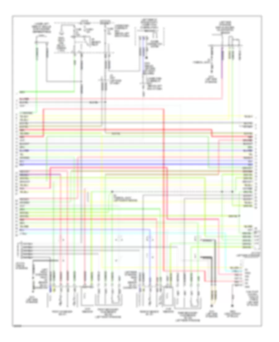
3.2L, Engine Performance Wiring Diagram, A/T (4 of 5) for Acura TL Type S 2007
 https://portal-diagnostov.com/license.html
Automotive Electricians Portal FZCO
Automotive Electricians Portal FZCO
https://portal-diagnostov.com/license.html
https://portal-diagnostov.com/license.html
Automotive Electricians Portal FZCO
Automotive Electricians Portal FZCOList of elements for 3.2L, Engine Performance Wiring Diagram, A/T (4 of 5) for Acura TL Type S 2007:
- (left side of engine)
- (left side of engine) g101
- (on transaxle) transmission range switch
- A/t clutch pressure control solenoid valves (on transmission housing)
- A/t gear ind/cruise control dimming circuit
- A/t gear position detection circuit
- A/t gear position ind drive circuit
- A/t gear position indicator brightness control & dimming circuit
- A11
- A13
- A14
- B10
- B18
- Computer data lines system
- Cpu/fail safe circuit/can controller
- Drive circuit
- Fast controller area network transceiver
- Fuse 7.5a
- G101
- G102 (on right front of engine)
- G501 (under left side of dash)
- Gauge control module
- Hot in on or start
- Icm
- Ignition coils (middle of engine)
- Ignition coils (rear of engine)
- Input shaft (mainshaft) speed sensor (in transmission housing)
- J/c c104 (middle of engine)
- J/c c506 (left side of dash)
- J/c c508 (left side of dash)
- Lcd back light
- Micu
- Mil ind
- P16
- P20
- Red
- S1 (thermal joint)
- S2 (thermal joint)
- Shift ind
- Starting/ charging system
- Under- dash fuse/ relay box (behind left end of dash)
- Warning drive circuit
- X20
- X34
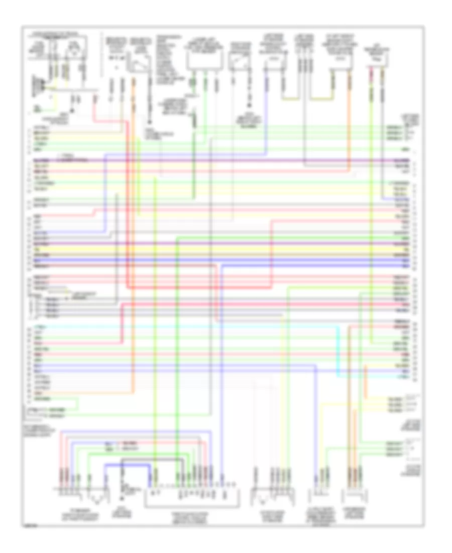
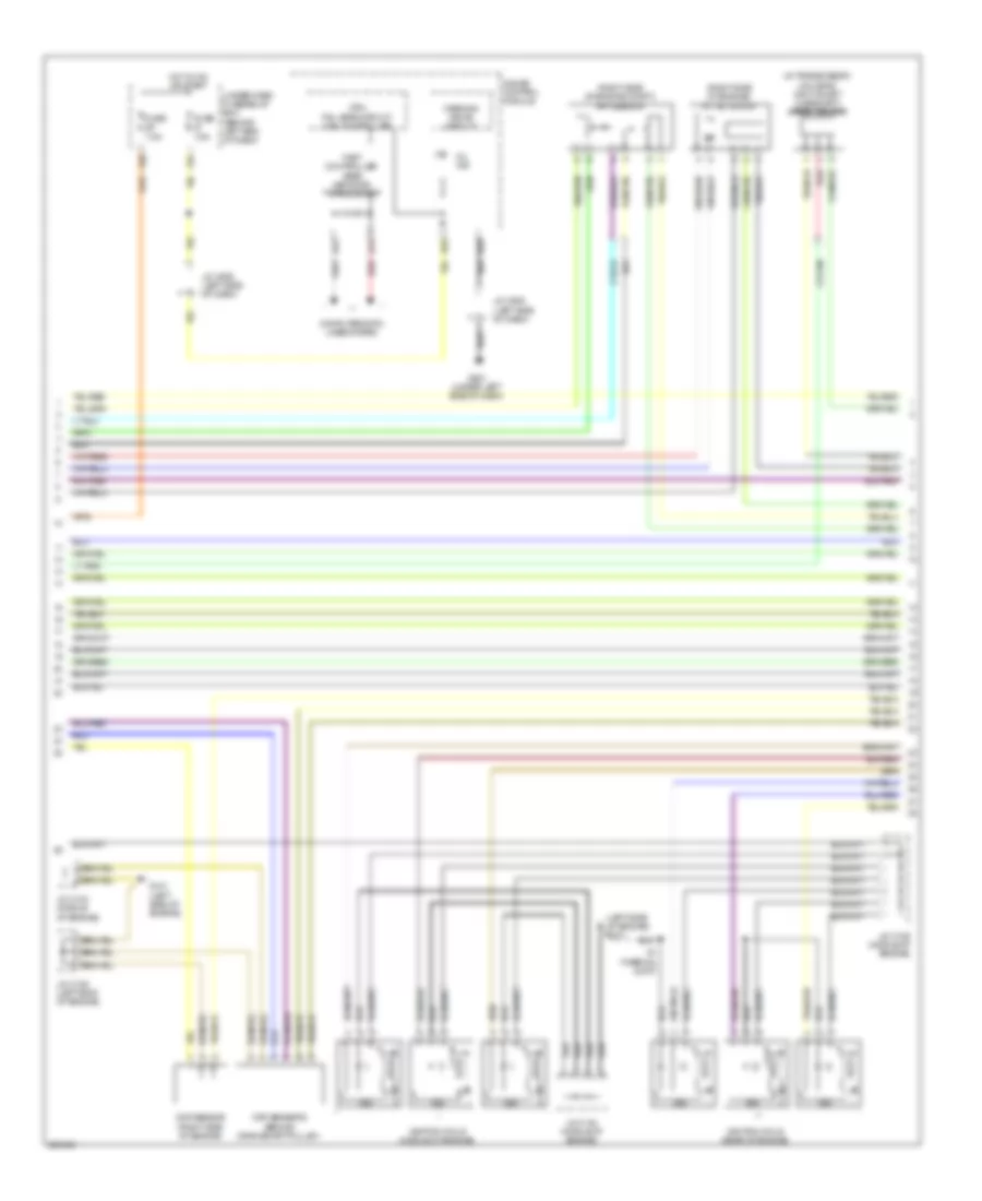
3.2L, Engine Performance Wiring Diagram, A/T (5 of 5) for Acura TL Type S 2007
 https://portal-diagnostov.com/license.html
Automotive Electricians Portal FZCO
Automotive Electricians Portal FZCO
https://portal-diagnostov.com/license.html
https://portal-diagnostov.com/license.html
Automotive Electricians Portal FZCO
Automotive Electricians Portal FZCOList of elements for 3.2L, Engine Performance Wiring Diagram, A/T (5 of 5) for Acura TL Type S 2007:
- (behind crankshaft pulley) ckp sensors
- (middle of engine) fuel injectors
- (middle of engine) j/c c104
- (on transmission) 2nd clutch transmission fluid pressure switch
- (right side of engine) cmp sensor
- (thermal joint) s2
- 3rd clutch transmission fluid pressure switch (on transmission)
- 4th clutch transmission fluid pressure switch (on transmission)
- A10
- A11
- A12
- A13
- A14
- A15
- A16
- A17
- A18
- A19
- A20
- A21
- A22
- A23
- A24
- A25
- A26
- A27
- A28
- A29
- A30
- A31
- Afshtcb1
- Afshtcb2
- Altc
- Altf
- Altl
- Atft
- Atpd
- Atpfwd
- Atpl
- Atpp
- Atpr
- Atprvs
- B15
- Barometer sensor
- C10
- C11
- C12
- C13
- C14
- C15
- C16
- C17
- C18
- C19
- C20
- C21
- C22
- Cable reel (b: on steering column) (c: on steering wheel)
- Cruise control system
- D10
- D11
- D12
- D13
- D14
- D15
- D16
- D17
- Ect 1
- Ect sensor 1 (left side of engine)
- Egrp
- Engine) g101
- Except type s
- G101 (left side of engine)
- G501 (under left side of dash)
- Iat
- Iat sensor (left side of engine)
- Igp
- Igpls1
- Igpls2
- Igpls3
- Igpls4
- Igpls5
- Igpls6
- Inj1
- Inj2
- Inj3
- Inj4
- Inj5
- Inj6
- J/c c105 (left side of engine)
- J/c c106 (middle of engine)
- Lg1
- Lsa
- Lsb
- Lsc
- Map
- Op2sw
- Op3sw
- Op4sw
- Pcm (behind center of dash)
- Pg1
- Pg2
- Ppin
- Red
- Rocker arm oil control solenoid (right side of engine)
- Rocker arm oil pressure switch (right side of engine)
- Sdnp
- Sedf
- Sefd
- Sg1
- Sg2
- Sha
- Shb
- Shc
- Shd
- Shift control solenoid valves
- Shift interlock system
- So2shtcb1
- So2shtcb2
- Starting/ charging system
- Steering wheel (type s)
- Steering wheel downshift (-) switch
- Steering wheel upshift (+) switch
- Supp
- Type s
- Vbsol
- Vbsol2
- Vcc1
- Vcc2
- Vlblb1
- Vlblb2
- Vtpsw
- Vts
3.2L, Engine Performance Wiring Diagram, M/T (1 of 5) for Acura TL Type S 2007
 https://portal-diagnostov.com/license.html
Automotive Electricians Portal FZCO
Automotive Electricians Portal FZCO
https://portal-diagnostov.com/license.html
https://portal-diagnostov.com/license.html
Automotive Electricians Portal FZCO
Automotive Electricians Portal FZCOList of elements for 3.2L, Engine Performance Wiring Diagram, M/T (1 of 5) for Acura TL Type S 2007:
- (behind left side of front bumper) g302
- A/f sensor relay
- Acc
- Active noise control unit (type s) (under middle
- Afshtcr
- Air conditioning system
- Anti-theft system
- Bksw
- Bkswnc
- Brake pedal position switch (near brake pedal)
- Can-h
- Can-l
- Clutch pedal position switch (near clutch pedal)
- Computer data lines system
- Cooling fans system
- Crmcls
- D13
- E10
- E11
- E12
- E13
- E14
- E15
- E16
- E17
- E18
- E19
- E20
- E21
- E22
- E23
- E24
- E25
- E26
- E27
- E28
- E29
- E30
- E31
- Ecm (behind center of dash)
- Eld
- Etcsrly
- Except type s
- Fan-l
- Fp+
- Fp-
- Fpc
- Fpcd
- Ftp
- Fuel pump
- Fuel pump control module (type s) (left side of trunk)
- Fuel tank pressure (ftp) sensor (under left rear of vehicle)
- Fuel tank unit (middle front of trunk)
- Fuse 15a
- Fuse 20a
- Fuse 7.5a
- G503 (under middle of dash)
- G603 (middle front of turnk)
- Gnd
- Hot at all times
- Hot in on or start
- Ig1
- Ignition coil relay
- Imocd
- Imofpr
- J/c c507 (left side of engine)
- Mrly
- N29
- Nep
- Of dash)
- Pgm-fi main relay 1
- Pgm-fi main relay 2
- Pnk
- Psp switch (right side of engine)
- Pspsw
- Red
- Rvs
- Scs
- Sg4
- Shift interlock system
- Type s
- Under-dash fuse/relay box (behind left end of dash)
- Under-hood fuse/relay box (left rear of engine compt)
- Vcc4
- Vssout
- Vsv
- Wen
- X10
- X31
- X32
- X36
- X38
3.2L, Engine Performance Wiring Diagram, M/T (2 of 5) for Acura TL Type S 2007
 https://portal-diagnostov.com/license.html
Automotive Electricians Portal FZCO
Automotive Electricians Portal FZCO
https://portal-diagnostov.com/license.html
https://portal-diagnostov.com/license.html
Automotive Electricians Portal FZCO
Automotive Electricians Portal FZCOList of elements for 3.2L, Engine Performance Wiring Diagram, M/T (2 of 5) for Acura TL Type S 2007:
- (left side of dash) j/c c508
- (under left rear of vehicle) evap canister vent shut valve
- Apsa
- Apsb
- Audio unit
- B10
- B11
- B12
- B13
- B14
- B15
- B16
- B17
- B18
- B19
- B20
- B21
- B22
- B23
- B24
- Barometer sensor
- C26
- Ckpa
- Ckpb
- Cmp
- Cooling fans system
- D10
- D11
- D12
- D13
- D14
- D15
- D16
- D17
- Ecm (behind center of dash)
- Ect2
- Egr
- Eld unit
- Fan-h
- Fuse 15a
- G302 (behind left side of front bumper)
- Hot at all times
- Ig1
- Imt+
- Imt-
- Imtm
- Ipb1
- Ipb2
- J/c c512 (under middle of dash)
- Lg2
- Mcs
- Moonroof control unit (rear of roof)
- Navigation unit (if equipped) (in trunk, below left side of package tray)
- Pcs
- Red
- Sg3
- Sho2sb1
- Sho2sb2
- Starting/ charging system
- Sts
- System charging starting/
- Throttle actuator control module relay (behind glove box)
- Under-dash fuse/relay box (behind left end of dash)
- Under-hood fuse/relay box (left rear of engine compt)
- Vbsol2
- Vcc3
- Vcentb1
- Vcentb2
- Vlblb1
- Vlblb2
- Vsb1
- Vsb2
- X23
3.2L, Engine Performance Wiring Diagram, M/T (3 of 5) for Acura TL Type S 2007
 https://portal-diagnostov.com/license.html
Automotive Electricians Portal FZCO
Automotive Electricians Portal FZCO
https://portal-diagnostov.com/license.html
https://portal-diagnostov.com/license.html
Automotive Electricians Portal FZCO
Automotive Electricians Portal FZCOList of elements for 3.2L, Engine Performance Wiring Diagram, M/T (3 of 5) for Acura TL Type S 2007:
- (at left side of engine compt, near strut tower) evap canister purge valve
- (left rear of engine) engine mount control solenoid valve
- (left side of engine) g101
- (left side of engine) j/c c105
- (middle front of trunk) (except type s) fuel tank unit
- (on top middle of engine, below intake manifold) knock sensor
- Braided
- Chip resistor
- Ect sensor 2 (under front of engine compt)
- Front a/f sensor (bank 2, sensor 1)
- Front secondary ho2s sensor (bank 2, sensor 2) (left front of engine)
- Fuel pump
- G101 (left side of engine)
- G603 (middle front of trunk)
- J/c c106 (middle of engine)
- Rear a/f sensor (bank 1, sensor 1)
- Rear secondary ho2s sensor (bank 1, sensor 2) (left rear of engine)
- Red
3.2L, Engine Performance Wiring Diagram, M/T (4 of 5) for Acura TL Type S 2007
 https://portal-diagnostov.com/license.html
Automotive Electricians Portal FZCO
Automotive Electricians Portal FZCO
https://portal-diagnostov.com/license.html
https://portal-diagnostov.com/license.html
Automotive Electricians Portal FZCO
Automotive Electricians Portal FZCOList of elements for 3.2L, Engine Performance Wiring Diagram, M/T (4 of 5) for Acura TL Type S 2007:
- (in transmission housing) input shaft (mainshaft) speed sensor
- (left side of engine) g101
- (right side of engine compt) app sensor
- (right side of engine) imt actuator
- A13
- A14
- B10
- B18
- Ckp sensors (behind crankshaft pulley)
- Cmp sensor (right side of engine)
- Computer data lines system
- Cpu/ fail safe circuit/ can controller
- Fast controller area network transceiver
- Fuse 7.5a
- G101 (left side of engine)
- G501 (under left side of dash)
- Gauge control module
- Hot in on or start
- Icm
- Ignition coils (middle of engine)
- Ignition coils (rear of engine)
- J/c c104 (middle of engine)
- J/c c105 (left side of engine)
- J/c c106 (middle of engine)
- J/c c506 (left side of dash)
- J/c c508 (left side of dash)
- Mil ind
- Red
- S1 (thermal joint)
- Under-dash fuse/relay box (behind left end of dash)
- Warning drive circuit
- X20
- X34
3.2L, Engine Performance Wiring Diagram, M/T (5 of 5) for Acura TL Type S 2007
 https://portal-diagnostov.com/license.html
Automotive Electricians Portal FZCO
Automotive Electricians Portal FZCO
https://portal-diagnostov.com/license.html
https://portal-diagnostov.com/license.html
Automotive Electricians Portal FZCO
Automotive Electricians Portal FZCOList of elements for 3.2L, Engine Performance Wiring Diagram, M/T (5 of 5) for Acura TL Type S 2007:
- (behind glove box) throttle actuator control module
- (in transmission housing) output shaft (countershaft) speed sensor
- (left side of engine) egr valve & egr valve position sensor
- (left side of engine) g101
- (left side of engine) j/c c105
- (left side of engine) map sensor
- (middle of engine) j/c c104
- (on throttle body) tp sensor/ throttle actuator
- A10
- A11
- A12
- A13
- A14
- A15
- A16
- A17
- A18
- A19
- A20
- A21
- A22
- A23
- A24
- A25
- A26
- A27
- A28
- A29
- A30
- A31
- Afshtcb1
- Afshtcb2
- Altc
- Altf
- Altl
- C10
- C11
- C12
- C13
- C14
- C15
- C16
- C17
- C18
- C19
- C20
- C21
- C22
- Ecm (behind center of dash)
- Ect sensor 1 (left side of engine)
- Ect1
- Egrp
- Except type s
- Fuel injectors (middle of engine)
- G101 (left side of engine)
- Gnd
- Iat
- Iat sensor (left side of engine)
- Igp
- Igpls1
- Igpls2
- Igpls3
- Igpls4
- Igpls5
- Igpls6
- Inj1
- Inj2
- Inj3
- Inj4
- Inj5
- Inj6
- J/c c104 (middle of engine)
- J/c c105 (left side of engine)
- Lg1
- Map
- Pg1
- Pg2
- Red
- Rocker arm oil control solenoid (right side of engine)
- Rocker arm oil pressure switch (right side of engine)
- S1 (thermal joint)
- S3 (thermal joint) (left side of engine)
- Sedf
- Sefd
- Sg1
- Sg2
- So2shtcb1
- So2shtcb2
- Starting/ charging system
- Starting/charging system
- Tpsa
- Tpsb
- Type s
- Vbsol
- Vcc
- Vcc1
- Vcc2
- Vtpsw
- Vts
3.5L
3.5L, Engine Performance Wiring Diagram, A/T (1 of 5) for Acura TL Type S 2007
 https://portal-diagnostov.com/license.html
Automotive Electricians Portal FZCO
Automotive Electricians Portal FZCO
https://portal-diagnostov.com/license.html
https://portal-diagnostov.com/license.html
Automotive Electricians Portal FZCO
Automotive Electricians Portal FZCOList of elements for 3.5L, Engine Performance Wiring Diagram, A/T (1 of 5) for Acura TL Type S 2007:
- (left side of dash) j/c c507
- (near brake pedal) brake pedal position switch
- (type s)
- (under middle of dash) j/c c512
- Acc
- Afshtcr
- Air conditioning system
- Anti-theft system
- App sensor (right side of engine compt)
- Apsa
- Apsb
- Atpn
- B10
- B11
- B12
- B13
- B14
- B15
- B16
- B17
- B18
- B19
- B20
- B21
- B22
- B23
- B24
- Bksw
- Bkswnc
- Braided
- Canh
- Canl
- Ckpa
- Ckpb
- Cmp
- Computer data lines system
- Cooling fans system
- E10
- E11
- E12
- E13
- E14
- E15
- E16
- E17
- E18
- E19
- E20
- E21
- E22
- E23
- E24
- E25
- E26
- E27
- E28
- E29
- E30
- E31
- Ect2
- Egr
- Eld
- Etcsrly
- Except type s
- Fanh
- Fanl
- Fpc
- Fpcd
- Ftp
- Fuse 15a
- Fuse 2 15a
- Fuse 20a
- G101 (left side of engine)
- Hot at all times
- Hot in on or start
- Ig1
- Ignition coil relay
- Imocd
- Imofpr
- Imt+
- Imt-
- Imtm
- Ipb1
- Ipb2
- Knock sensor (on top middle of engine, below intake manifold)
- Lg2
- Mcs
- Moonroof control unit (rear of roof)
- Mrly
- Navigation unit (if equipped) (in trunk, below left side of package tray)
- Pcm (behind center of dash)
- Pcs
- Pgm-fi main relay 1
- Pgm-fi main relay 2
- Pnk
- Pspsw
- Red
- Scs
- Sdn
- Sg3
- Sg4
- Shift inter- lock system
- Sho2sb1
- Sho2sb2
- Sls
- Smode
- Sound systems
- Starting/charging system
- Strld
- Strly
- Sts
- Sup
- Throttle actuator control module relay (behind glove box)
- To fuse 23 (diagram 3 of 5)
- Type s
- Under- dash fuse/ relay box (behind left end of dash)
- Under-hood fuse/relay box (left rear of engine compt)
- Vcc3
- Vcc4
- Vcentb1
- Vcentb2
- Vsb1
- Vsb2
- Vsp
- Vssout
- Vsv
- Wen
- X23
- X31
- X32
- X38
3.5L, Engine Performance Wiring Diagram, A/T (2 of 5) for Acura TL Type S 2007
 https://portal-diagnostov.com/license.html
Automotive Electricians Portal FZCO
Automotive Electricians Portal FZCO
https://portal-diagnostov.com/license.html
https://portal-diagnostov.com/license.html
Automotive Electricians Portal FZCO
Automotive Electricians Portal FZCOList of elements for 3.5L, Engine Performance Wiring Diagram, A/T (2 of 5) for Acura TL Type S 2007:
- (at left side of engine compt, near strut tower) evap canister purge valve
- (left rear of engine) engine mount control solenoid valve
- (left side of dash) j/c c508
- (left side of engine)
- (left side of engine) j/c c105
- (middle front of trunk) fuel tank unit
- (right side of engine) psp switch
- (under left rear of vehicle) fuel tank pressure (ftp) sensor
- Atf temperature sensor
- E16
- Ect sensor 2 (under front of engine compt)
- Except type s
- Fuel gauge sending unit
- Fuel pump
- G101 (left side of engine)
- G302 (behind left side of front bumper)
- G503 (under middle of dash)
- G603 (middle front of trunk)
- Imt actuator (right side of engine)
- Instrument cluster system
- J/c c105
- J/c c105 (left side of engine)
- J/c c106 (middle of engine)
- Map sensor (left side of engine)
- Output shaft (countershaft) speed sensor (in transmission housing)
- Pg2
- Pnk
- Red
- Sedf
- Sefd
- Sequential sportshift a/t shift switch
- Sequential sportshift mode switch
- Throttle actuator control module (behind glove box)
- Tp sensor/ throttle actuator (on throttle body)
- Tpsa
- Tpsb
- Transmission gear selection switch/ park pin switch/ a/t gear position indicator panel light (under center console)
- Type s
- Under-dash fuse/relay box (behind left end of dash) x5
- Vcc
3.5L, Engine Performance Wiring Diagram, A/T (3 of 5) for Acura TL Type S 2007
 https://portal-diagnostov.com/license.html
Automotive Electricians Portal FZCO
Automotive Electricians Portal FZCO
https://portal-diagnostov.com/license.html
https://portal-diagnostov.com/license.html
Automotive Electricians Portal FZCO
Automotive Electricians Portal FZCOList of elements for 3.5L, Engine Performance Wiring Diagram, A/T (3 of 5) for Acura TL Type S 2007:
- (b1, s1) connector
- (left front of engine) front a/f sensor (b2, s1) connector
- (left rear of engine compt) under-hood fuse/relay box
- (left side of engine) egr valve & egr valve position sensor
- (under left rear of vehicle) evap canister vent shut valve
- A/f sensor relay
- Braided
- Chip resistor
- D13
- Eld unit
- Fp+
- Fp-
- Fpc
- Fpcd
- From pgm fi main relay 1 (diagram 1 of 5)
- Front a/f sensor (b2, s1)
- Front secondary ho2s sensor (b2, s2) (left front of engine)
- Fuel pump control module (type s) (left side of trunk)
- Fuse 15a
- Fuse 4 15a
- Fuse 7.5a
- G101 (left side of engine)
- G302 (behind left side of front bumper)
- G603 (middle front of trunk)
- Gnd
- Hot at all times
- Hot in on or start
- Ig1
- J/c c104 (middle of engine)
- J/c c105 (left side of engine)
- J/c c507 (left side of dash)
- N29
- Pnk
- Power distribution system
- Rear a/f sensor (b1, s1)
- Rear secondary ho2s sensor (b1, s2) (left rear of engine)
- Red
- S1 (thermal joint)
- S3 (thermal joint) (left side of engine)
- Under-dash fuse/relay box (behind left end of dash)
- X10
- X36
3.5L, Engine Performance Wiring Diagram, A/T (4 of 5) for Acura TL Type S 2007
 https://portal-diagnostov.com/license.html
Automotive Electricians Portal FZCO
Automotive Electricians Portal FZCO
https://portal-diagnostov.com/license.html
https://portal-diagnostov.com/license.html
Automotive Electricians Portal FZCO
Automotive Electricians Portal FZCOList of elements for 3.5L, Engine Performance Wiring Diagram, A/T (4 of 5) for Acura TL Type S 2007:
- (left side of engine)
- (left side of engine) g101
- (on transaxle) transmission range switch
- A/t clutch pressure control solenoid valves (on transmission housing)
- A/t gear ind/cruise control dimming circuit
- A/t gear position detection circuit
- A/t gear position ind drive circuit
- A/t gear position indicator brightness control & dimming circuit
- A11
- A13
- A14
- B10
- B18
- Computer data lines system
- Cpu/fail safe circuit/can controller
- Drive circuit
- Fast controller area network transceiver
- Fuse 7.5a
- G101
- G102 (on right front of engine)
- G501 (under left side of dash)
- Gauge control module
- Hot in on or start
- Icm
- Ignition coils (middle of engine)
- Ignition coils (rear of engine)
- Input shaft (mainshaft) speed sensor (in transmission housing)
- J/c c104 (middle of engine)
- J/c c506 (left side of dash)
- J/c c508 (left side of dash)
- Lcd back light
- Micu
- Mil ind
- P16
- P20
- Red
- S1 (thermal joint)
- S2 (thermal joint)
- Shift ind
- Starting/ charging system
- Under- dash fuse/ relay box (behind left end of dash)
- Warning drive circuit
- X20
- X34
3.5L, Engine Performance Wiring Diagram, A/T (5 of 5) for Acura TL Type S 2007
 https://portal-diagnostov.com/license.html
Automotive Electricians Portal FZCO
Automotive Electricians Portal FZCO
https://portal-diagnostov.com/license.html
https://portal-diagnostov.com/license.html
Automotive Electricians Portal FZCO
Automotive Electricians Portal FZCOList of elements for 3.5L, Engine Performance Wiring Diagram, A/T (5 of 5) for Acura TL Type S 2007:
- (behind crankshaft pulley) ckp sensors
- (middle of engine) fuel injectors
- (middle of engine) j/c c104
- (on transmission) 2nd clutch transmission fluid pressure switch
- (right side of engine) cmp sensor
- (thermal joint) s2
- 3rd clutch transmission fluid pressure switch (on transmission)
- 4th clutch transmission fluid pressure switch (on transmission)
- A10
- A11
- A12
- A13
- A14
- A15
- A16
- A17
- A18
- A19
- A20
- A21
- A22
- A23
- A24
- A25
- A26
- A27
- A28
- A29
- A30
- A31
- Afshtcb1
- Afshtcb2
- Altc
- Altf
- Altl
- Atft
- Atpd
- Atpfwd
- Atpl
- Atpp
- Atpr
- Atprvs
- B15
- Barometer sensor
- C10
- C11
- C12
- C13
- C14
- C15
- C16
- C17
- C18
- C19
- C20
- C21
- C22
- Cable reel (b: on steering column) (c: on steering wheel)
- Cruise control system
- D10
- D11
- D12
- D13
- D14
- D15
- D16
- D17
- Ect 1
- Ect sensor 1 (left side of engine)
- Egrp
- Engine) g101
- Except type s
- G101 (left side of engine)
- G501 (under left side of dash)
- Iat
- Iat sensor (left side of engine)
- Igp
- Igpls1
- Igpls2
- Igpls3
- Igpls4
- Igpls5
- Igpls6
- Inj1
- Inj2
- Inj3
- Inj4
- Inj5
- Inj6
- J/c c105 (left side of engine)
- J/c c106 (middle of engine)
- Lg1
- Lsa
- Lsb
- Lsc
- Map
- Op2sw
- Op3sw
- Op4sw
- Pcm (behind center of dash)
- Pg1
- Pg2
- Ppin
- Red
- Rocker arm oil control solenoid (right side of engine)
- Rocker arm oil pressure switch (right side of engine)
- Sdnp
- Sedf
- Sefd
- Sg1
- Sg2
- Sha
- Shb
- Shc
- Shd
- Shift control solenoid valves
- Shift interlock system
- So2shtcb1
- So2shtcb2
- Starting/ charging system
- Steering wheel (type s)
- Steering wheel downshift (-) switch
- Steering wheel upshift (+) switch
- Supp
- Type s
- Vbsol
- Vbsol2
- Vcc1
- Vcc2
- Vlblb1
- Vlblb2
- Vtpsw
- Vts
3.5L, Engine Performance Wiring Diagram, M/T (1 of 5) for Acura TL Type S 2007
 https://portal-diagnostov.com/license.html
Automotive Electricians Portal FZCO
Automotive Electricians Portal FZCO
https://portal-diagnostov.com/license.html
https://portal-diagnostov.com/license.html
Automotive Electricians Portal FZCO
Automotive Electricians Portal FZCOList of elements for 3.5L, Engine Performance Wiring Diagram, M/T (1 of 5) for Acura TL Type S 2007:
- (behind left side of front bumper) g302
- A/f sensor relay
- Acc
- Active noise control unit (type s) (under middle
- Afshtcr
- Air conditioning system
- Anti-theft system
- Bksw
- Bkswnc
- Brake pedal position switch (near brake pedal)
- Can-h
- Can-l
- Clutch pedal position switch (near clutch pedal)
- Computer data lines system
- Cooling fans system
- Crmcls
- D13
- E10
- E11
- E12
- E13
- E14
- E15
- E16
- E17
- E18
- E19
- E20
- E21
- E22
- E23
- E24
- E25
- E26
- E27
- E28
- E29
- E30
- E31
- Ecm (behind center of dash)
- Eld
- Etcsrly
- Except type s
- Fan-l
- Fp+
- Fp-
- Fpc
- Fpcd
- Ftp
- Fuel pump
- Fuel pump control module (type s) (left side of trunk)
- Fuel tank pressure (ftp) sensor (under left rear of vehicle)
- Fuel tank unit (middle front of trunk)
- Fuse 15a
- Fuse 20a
- Fuse 7.5a
- G503 (under middle of dash)
- G603 (middle front of turnk)
- Gnd
- Hot at all times
- Hot in on or start
- Ig1
- Ignition coil relay
- Imocd
- Imofpr
- J/c c507 (left side of engine)
- Mrly
- N29
- Nep
- Of dash)
- Pgm-fi main relay 1
- Pgm-fi main relay 2
- Pnk
- Psp switch (right side of engine)
- Pspsw
- Red
- Rvs
- Scs
- Sg4
- Shift interlock system
- Type s
- Under-dash fuse/relay box (behind left end of dash)
- Under-hood fuse/relay box (left rear of engine compt)
- Vcc4
- Vssout
- Vsv
- Wen
- X10
- X31
- X32
- X36
- X38
3.5L, Engine Performance Wiring Diagram, M/T (2 of 5) for Acura TL Type S 2007
 https://portal-diagnostov.com/license.html
Automotive Electricians Portal FZCO
Automotive Electricians Portal FZCO
https://portal-diagnostov.com/license.html
https://portal-diagnostov.com/license.html
Automotive Electricians Portal FZCO
Automotive Electricians Portal FZCOList of elements for 3.5L, Engine Performance Wiring Diagram, M/T (2 of 5) for Acura TL Type S 2007:
- (left side of dash) j/c c508
- (under left rear of vehicle) evap canister vent shut valve
- Apsa
- Apsb
- Audio unit
- B10
- B11
- B12
- B13
- B14
- B15
- B16
- B17
- B18
- B19
- B20
- B21
- B22
- B23
- B24
- Barometer sensor
- C26
- Ckpa
- Ckpb
- Cmp
- Cooling fans system
- D10
- D11
- D12
- D13
- D14
- D15
- D16
- D17
- Ecm (behind center of dash)
- Ect2
- Egr
- Eld unit
- Fan-h
- Fuse 15a
- G302 (behind left side of front bumper)
- Hot at all times
- Ig1
- Imt+
- Imt-
- Imtm
- Ipb1
- Ipb2
- J/c c512 (under middle of dash)
- Lg2
- Mcs
- Moonroof control unit (rear of roof)
- Navigation unit (if equipped) (in trunk, below left side of package tray)
- Pcs
- Red
- Sg3
- Sho2sb1
- Sho2sb2
- Starting/ charging system
- Sts
- System charging starting/
- Throttle actuator control module relay (behind glove box)
- Under-dash fuse/relay box (behind left end of dash)
- Under-hood fuse/relay box (left rear of engine compt)
- Vbsol2
- Vcc3
- Vcentb1
- Vcentb2
- Vlblb1
- Vlblb2
- Vsb1
- Vsb2
- X23
3.5L, Engine Performance Wiring Diagram, M/T (3 of 5) for Acura TL Type S 2007
 https://portal-diagnostov.com/license.html
Automotive Electricians Portal FZCO
Automotive Electricians Portal FZCO
https://portal-diagnostov.com/license.html
https://portal-diagnostov.com/license.html
Automotive Electricians Portal FZCO
Automotive Electricians Portal FZCOList of elements for 3.5L, Engine Performance Wiring Diagram, M/T (3 of 5) for Acura TL Type S 2007:
- (at left side of engine compt, near strut tower) evap canister purge valve
- (left rear of engine) engine mount control solenoid valve
- (left side of engine) g101
- (left side of engine) j/c c105
- (middle front of trunk) (except type s) fuel tank unit
- (on top middle of engine, below intake manifold) knock sensor
- Braided
- Chip resistor
- Ect sensor 2 (under front of engine compt)
- Front a/f sensor (bank 2, sensor 1)
- Front secondary ho2s sensor (bank 2, sensor 2) (left front of engine)
- Fuel pump
- G101 (left side of engine)
- G603 (middle front of trunk)
- J/c c106 (middle of engine)
- Rear a/f sensor (bank 1, sensor 1)
- Rear secondary ho2s sensor (bank 1, sensor 2) (left rear of engine)
- Red
3.5L, Engine Performance Wiring Diagram, M/T (4 of 5) for Acura TL Type S 2007
 https://portal-diagnostov.com/license.html
Automotive Electricians Portal FZCO
Automotive Electricians Portal FZCO
https://portal-diagnostov.com/license.html
https://portal-diagnostov.com/license.html
Automotive Electricians Portal FZCO
Automotive Electricians Portal FZCOList of elements for 3.5L, Engine Performance Wiring Diagram, M/T (4 of 5) for Acura TL Type S 2007:
- (in transmission housing) input shaft (mainshaft) speed sensor
- (left side of engine) g101
- (right side of engine compt) app sensor
- (right side of engine) imt actuator
- A13
- A14
- B10
- B18
- Ckp sensors (behind crankshaft pulley)
- Cmp sensor (right side of engine)
- Computer data lines system
- Cpu/ fail safe circuit/ can controller
- Fast controller area network transceiver
- Fuse 7.5a
- G101 (left side of engine)
- G501 (under left side of dash)
- Gauge control module
- Hot in on or start
- Icm
- Ignition coils (middle of engine)
- Ignition coils (rear of engine)
- J/c c104 (middle of engine)
- J/c c105 (left side of engine)
- J/c c106 (middle of engine)
- J/c c506 (left side of dash)
- J/c c508 (left side of dash)
- Mil ind
- Red
- S1 (thermal joint)
- Under-dash fuse/relay box (behind left end of dash)
- Warning drive circuit
- X20
- X34
3.5L, Engine Performance Wiring Diagram, M/T (5 of 5) for Acura TL Type S 2007
 https://portal-diagnostov.com/license.html
Automotive Electricians Portal FZCO
Automotive Electricians Portal FZCO
https://portal-diagnostov.com/license.html
https://portal-diagnostov.com/license.html
Automotive Electricians Portal FZCO
Automotive Electricians Portal FZCOList of elements for 3.5L, Engine Performance Wiring Diagram, M/T (5 of 5) for Acura TL Type S 2007:
- (behind glove box) throttle actuator control module
- (in transmission housing) output shaft (countershaft) speed sensor
- (left side of engine) egr valve & egr valve position sensor
- (left side of engine) g101
- (left side of engine) j/c c105
- (left side of engine) map sensor
- (middle of engine) j/c c104
- (on throttle body) tp sensor/ throttle actuator
- A10
- A11
- A12
- A13
- A14
- A15
- A16
- A17
- A18
- A19
- A20
- A21
- A22
- A23
- A24
- A25
- A26
- A27
- A28
- A29
- A30
- A31
- Afshtcb1
- Afshtcb2
- Altc
- Altf
- Altl
- C10
- C11
- C12
- C13
- C14
- C15
- C16
- C17
- C18
- C19
- C20
- C21
- C22
- Ecm (behind center of dash)
- Ect sensor 1 (left side of engine)
- Ect1
- Egrp
- Except type s
- Fuel injectors (middle of engine)
- G101 (left side of engine)
- Gnd
- Iat
- Iat sensor (left side of engine)
- Igp
- Igpls1
- Igpls2
- Igpls3
- Igpls4
- Igpls5
- Igpls6
- Inj1
- Inj2
- Inj3
- Inj4
- Inj5
- Inj6
- J/c c104 (middle of engine)
- J/c c105 (left side of engine)
- Lg1
- Map
- Pg1
- Pg2
- Red
- Rocker arm oil control solenoid (right side of engine)
- Rocker arm oil pressure switch (right side of engine)
- S1 (thermal joint)
- S3 (thermal joint) (left side of engine)
- Sedf
- Sefd
- Sg1
- Sg2
- So2shtcb1
- So2shtcb2
- Starting/ charging system
- Starting/charging system
- Tpsa
- Tpsb
- Type s
- Vbsol
- Vcc
- Vcc1
- Vcc2
- Vtpsw
- Vts
EXTERIOR LIGHTS
Backup Lamps Wiring Diagram, A/T for Acura TL Type S 2007
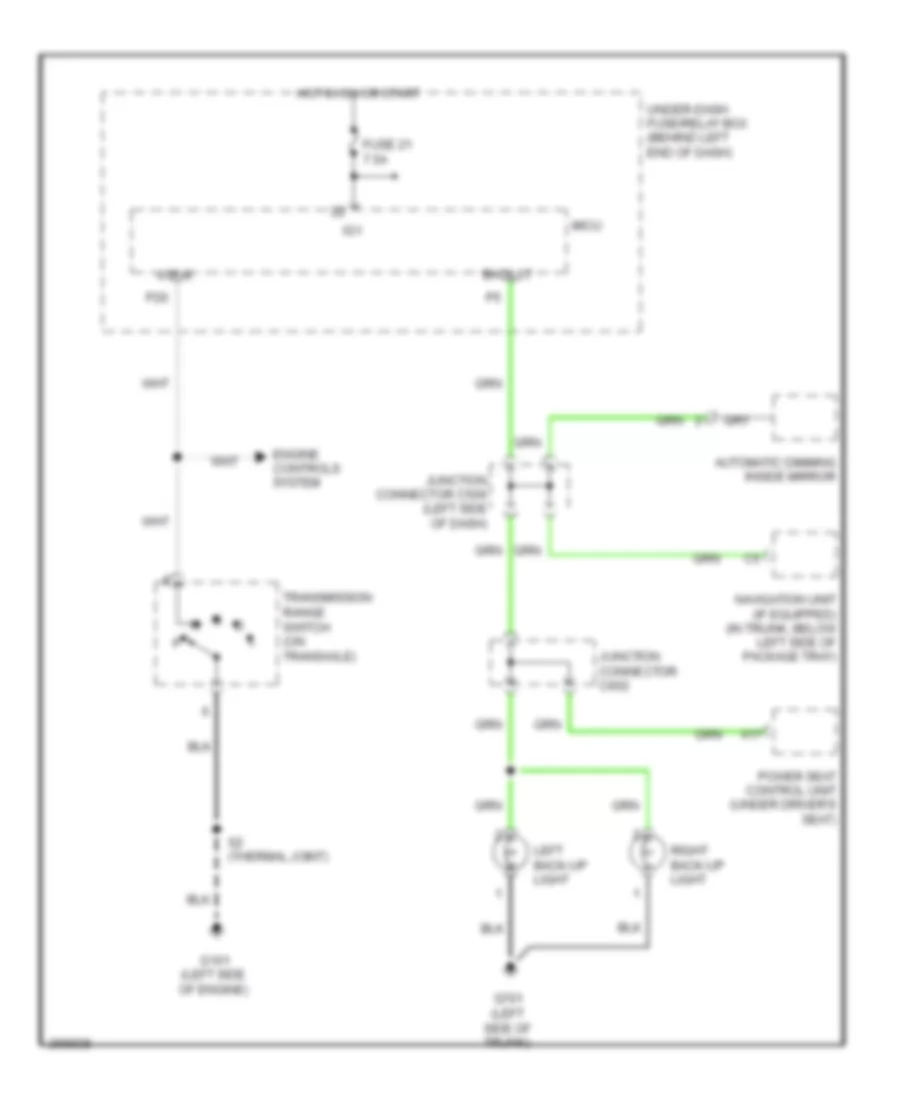 https://portal-diagnostov.com/license.html
Automotive Electricians Portal FZCO
Automotive Electricians Portal FZCO
https://portal-diagnostov.com/license.html
https://portal-diagnostov.com/license.html
Automotive Electricians Portal FZCO
Automotive Electricians Portal FZCOList of elements for Backup Lamps Wiring Diagram, A/T for Acura TL Type S 2007:
- A17
- Atp-r
- Automatic dimming inside mirror
- Back lt
- Engine controls system
- Fuse 21 7.5a
- G101 (left side of engine)
- G701 (left side of trunk)
- Hot in on or start
- Ig1
- Junction connector c506 (left side of dash)
- Junction connector c602
- Left back-up light
- Micu
- Navigation unit (if equipped) (in trunk, below left side of package tray)
- P20
- Power seat control unit (under driver's seat)
- Right back-up light
- S2 (thermal joint)
- Transmission range switch (on transaxle)
- Under-dash fuse/relay box (behind left end of dash)
Backup Lamps Wiring Diagram, M/T for Acura TL Type S 2007
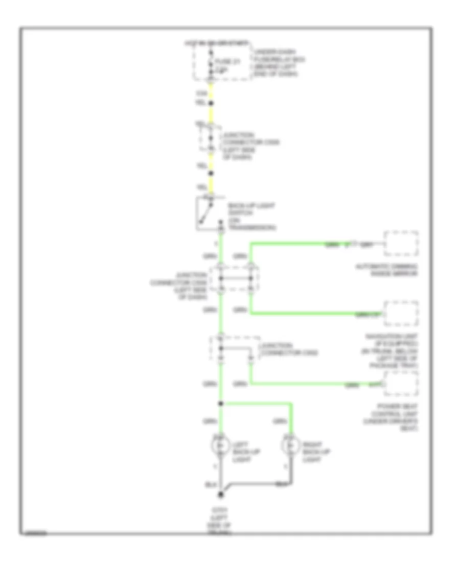 https://portal-diagnostov.com/license.html
Automotive Electricians Portal FZCO
Automotive Electricians Portal FZCO
https://portal-diagnostov.com/license.html
https://portal-diagnostov.com/license.html
Automotive Electricians Portal FZCO
Automotive Electricians Portal FZCOList of elements for Backup Lamps Wiring Diagram, M/T for Acura TL Type S 2007:
- A17
- Automatic dimming inside mirror
- Back-up light switch (on transmission)
- Fuse 21 7.5a
- G701 (left side of trunk)
- Hot in on or start
- Junction connector c506 (left side of dash)
- Junction connector c602
- Left back-up light
- Navigation unit (if equipped) (in trunk, below left side of package tray)
- Power seat control unit (under driver's seat)
- Right back-up light
- Under-dash fuse/relay box (behind left end of dash)
- X34
Exterior Lamps Wiring Diagram (1 of 2) for Acura TL Type S 2007
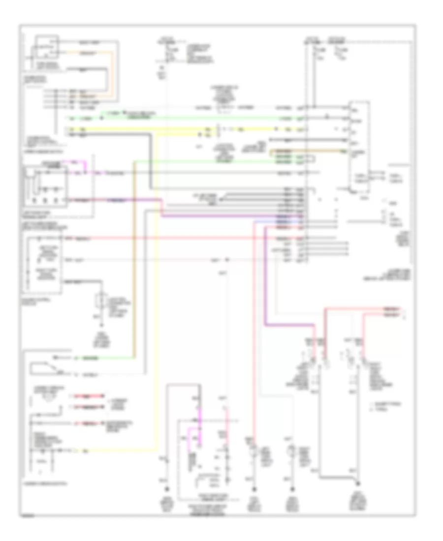 https://portal-diagnostov.com/license.html
Automotive Electricians Portal FZCO
Automotive Electricians Portal FZCO
https://portal-diagnostov.com/license.html
https://portal-diagnostov.com/license.html
Automotive Electricians Portal FZCO
Automotive Electricians Portal FZCOList of elements for Exterior Lamps Wiring Diagram (1 of 2) for Acura TL Type S 2007:
- (at left rear of trunk) g601
- (not used)
- (under middle of dash) junction connector c510
- B-can
- B10
- B12
- B15
- B16
- Combination light switch
- Combination switch control unit
- Computer data lines system
- D17
- Defogger system
- Except type s
- F10
- Front passenger's air bag cut-off indicator
- Fuse 15a
- Fuse 7.5a
- G301 (behind left side of front bumper)
- G501 (under left side of dash)
- G502 (under left side of dash)
- G506 (behind glove box)
- G604 (right side of trunk)
- G701 (left side of trunk)
- Gauge control module
- Gnd
- Hazard sw
- Hazard warning switch
- Hazard warning switch light
- Hot at all times
- Hot in on or start
- Ig1
- Interior lights system
- Junction connector c506 (left side of dash)
- Junction connector c508 (left side of dash)
- Left front turn signal/ parking/ side marker lights
- Left power mirror (front of driver's door)
- Left rear turn signal light
- Left side turn signal light
- Left turn signal indicator
- M/t
- Micu
- N27
- N33
- N38
- N42
- N44
- N45
- Off
- P28
- Red
- Right front turn signal/ parking/ side marker lights
- Right power mirror (front of front passenger's door)
- Right rear turn signal light
- Right side turn signal light
- Right turn signal indicator
- Sg-1
- Turn l
- Turn r
- Turn signal light switch
- Turn signal/ hazard relay
- Type s
- Under-dash fuse/relay box (behind left end of dash)
- Under-hood fuse/relay box (left rear of engine compt)
- Vbu
- Wiper/washer switch
- X27
- X34
- X35
Exterior Lamps Wiring Diagram (2 of 2) for Acura TL Type S 2007
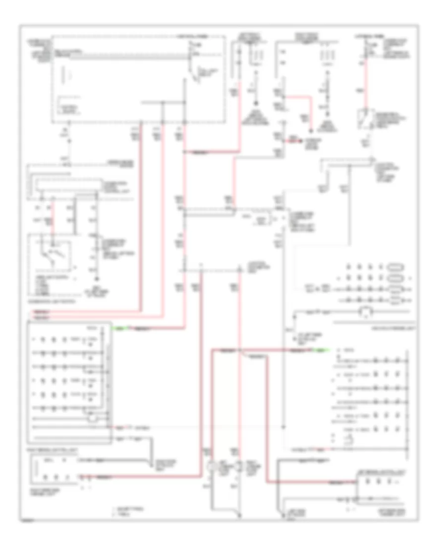 https://portal-diagnostov.com/license.html
Automotive Electricians Portal FZCO
Automotive Electricians Portal FZCO
https://portal-diagnostov.com/license.html
https://portal-diagnostov.com/license.html
Automotive Electricians Portal FZCO
Automotive Electricians Portal FZCOList of elements for Exterior Lamps Wiring Diagram (2 of 2) for Acura TL Type S 2007:
- (at left rear of trunk) g601
- (left side of trunk) g701
- (right side of trunk) g604
- B12
- Brake pedal position switch (near brake pedal)
- Combination light switch
- Combination switch control unit
- Control block
- Except type s
- F12
- Fuse 10a
- Fuse 20a
- G302 (behind left side of front bumper)
- G506 (behind glove box)
- G601 (at left rear of trunk)
- H13
- H14
- Headlight switch 0) off 1) park 2) auto 3) head
- High mount brake light
- Hot at all times
- Interior lights system
- Junction connector c507 (left side of dash)
- Junction connector c602
- Left brake light/taillight
- Left front side marker light
- Left license plate light
- Left rear side marker light
- Micu
- N26
- N31
- N42
- Red
- Relay control module
- Right brake light/taillight
- Right front side marker light
- Right license plate light
- Right rear side marker light
- Stop sw
- Tail light relay
- Type s
- Under-dash fuse/relay box (behind left end of dash)
- Under-hood fuse/relay box (left rear of engine compt)
- Wiper/washer switch
GROUND DISTRIBUTION
Ground Distribution Wiring Diagram (1 of 4) for Acura TL Type S 2007
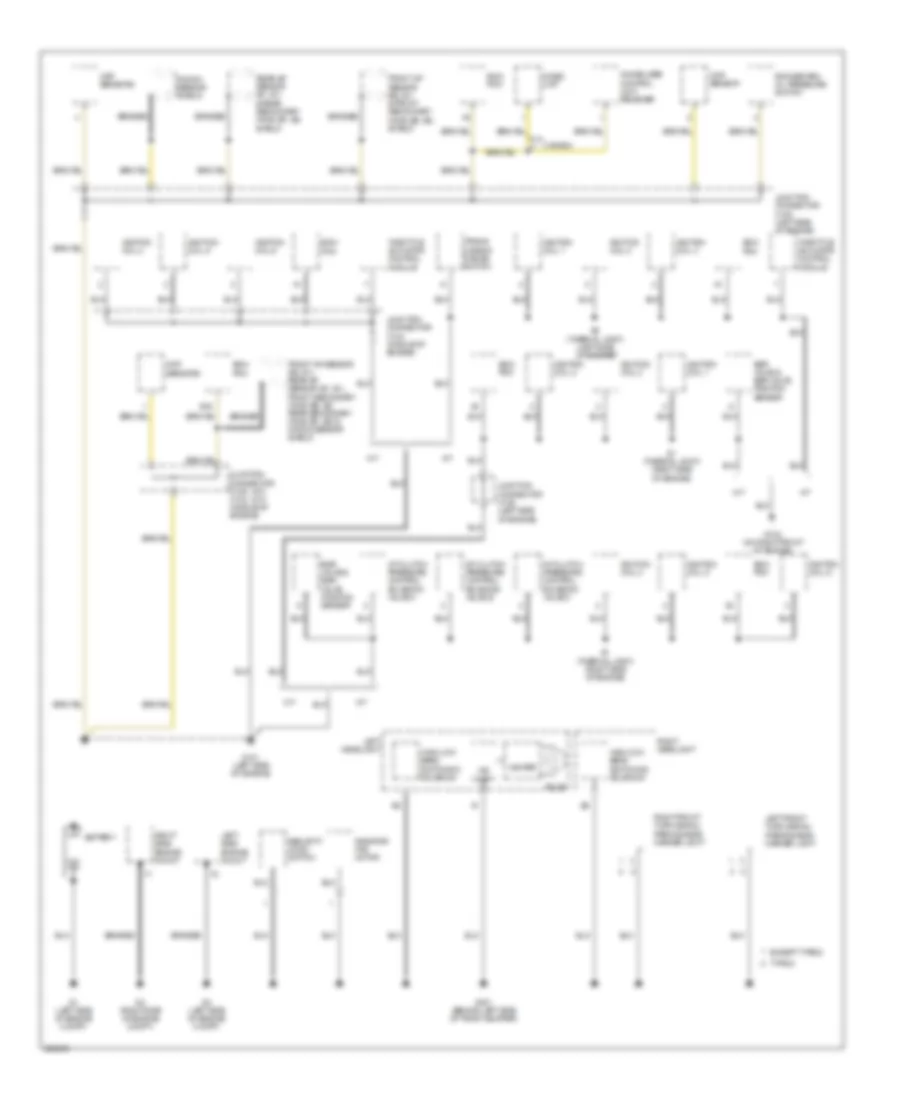 https://portal-diagnostov.com/license.html
Automotive Electricians Portal FZCO
Automotive Electricians Portal FZCO
https://portal-diagnostov.com/license.html
https://portal-diagnostov.com/license.html
Automotive Electricians Portal FZCO
Automotive Electricians Portal FZCOList of elements for Ground Distribution Wiring Diagram (1 of 4) for Acura TL Type S 2007:
- (a/t) (m/t)
- A/t
- A/t clutch pressure control solenoid valve a
- A/t clutch pressure control solenoid valve b
- A/t clutch pressure control solenoid valve c
- B15
- Battery
- Braided
- Bulb
- Canada
- Ckp sensors
- Cmp sensor
- Ecm/ pcm
- Egr valve & egr valve position sensor
- Except type s
- Front a/f sensor (b2, s1) & front secondary ho2s (b2, s2) shield
- Front a/f sensor (b2, s1), rear a/f sensor (b1, s1), front secondary ho2s (b2, s2) rear secondary ho2s (b1, s2) & knock sensor shield
- G1 (left side of engine compt)
- G101 (left side of engine)
- G102 (on right front of engine)
- G2 (right side of engine compt)
- G3 (left side of engine compt)
- G301 (behind left side of front bumper)
- Hid unit
- High/low beam switching solenoid
- Igniter
- Ignition coil 1
- Ignition coil 2
- Ignition coil 3
- Ignition coil 4
- Ignition coil 5
- Ignition coil 6
- Immobilizer control unit- receiver
- Imoes unit
- Junction connector c104 (middle of engine)
- Junction connector c105 (left side of engine)
- Junction connector c106 c104 (middle of engine)
- Knock sensor shield
- Left front turn signal/ parking/side marker light
- Left headlight
- Left side engine mount
- M/t
- Radiator fan motor
- Rear a/f sensor (b1, s1) & rear secondary ho2s (b1, s2) shield
- Right front turn signal/ parking/side marker light
- Right headlight
- Right side engine mount
- Rocker arm oil pressure switch
- S1 (thermal joint) (right side of engine)
- S2 (thermal joint) (left side of engine)
- Security hood switch
- Throttle actuator control module
- Trans- mission range switch
- Type s
Ground Distribution Wiring Diagram (2 of 4) for Acura TL Type S 2007
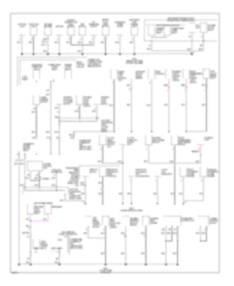 https://portal-diagnostov.com/license.html
Automotive Electricians Portal FZCO
Automotive Electricians Portal FZCO
https://portal-diagnostov.com/license.html
https://portal-diagnostov.com/license.html
Automotive Electricians Portal FZCO
Automotive Electricians Portal FZCOList of elements for Ground Distribution Wiring Diagram (2 of 4) for Acura TL Type S 2007:
- (a/t)
- (canada) washer fluid level switch
- (left rear of engine compt) under-hood fuse/relay box
- (m/t)
- A/c pressure switch
- A20
- Accessory power socket relay
- Audio-hvac sub display unit (w/ navigation)
- Automatic dimming inside mirror
- Blower motor relay
- Brake fluid level switch
- Canada
- Climate control unit
- Clock (w/o navigation)
- Clutch interlock switch (m/t)
- Clutch pedal position switch (m/t)
- Console accessory power socket
- Console light
- Ctrl block
- Data link connector
- Defogger
- Driver's door key cylinder switch
- Driver's door lock knob switch
- Driver's door lock switch
- Driver's seat belt buckle switch
- Driver's seat heater
- Driver's seat heater switch
- Driver's vanity mirror light switch
- Eld unit
- Front accessory power socket
- Front passenger's seat heater switch
- Front passenger's vanity mirror light switch
- G302 (behind left side of front bumper)
- G503 (under middle of dash)
- G601 (at left rear of trunk)
- Gnd
- Hands free link control unit
- High mount brake light
- Intermittent wiper relay
- Junction connector c509 (under left side of dash)
- Junction connector c635 (in left front door)
- K10
- Keyless buzzer
- Left drl
- Left fog light
- Left front side marker light
- Left power mirror
- Left rear door lock knob switch
- Left rear power window switch
- Left side turn signal light
- Lumbar support switch
- Micu
- Micu service check connector
- N17
- N18
- N42
- Park pin switch
- Pnk
- Power seat control unit
- Psp switch
- Red
- Relay control module
- Right fog light
- Roof console
- Sequential sportshift mode/ a/t switch
- Sg-2
- Transmission gear selection switch/ a/t gear position indicator panel light (a/t)
- Turn signal/ hazard relay
- Under-dash fuse/relay box (behind left end of dash)
- Under-hood fuse/relay box (left rear of engine compt)
- Washer motor relay
- Windshield wiper high relay
- Windshield wiper motor
- Wiper/ washer switch
Ground Distribution Wiring Diagram (3 of 4) for Acura TL Type S 2007
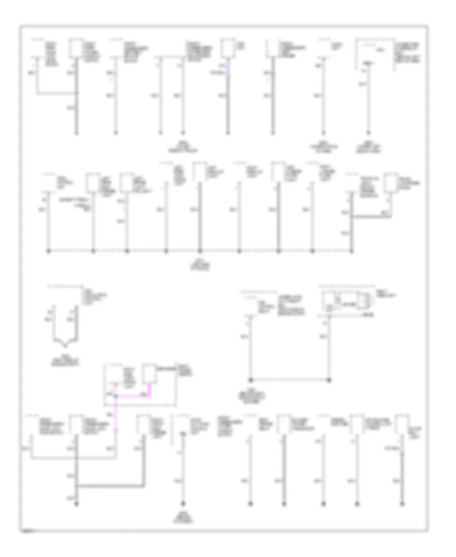 https://portal-diagnostov.com/license.html
Automotive Electricians Portal FZCO
Automotive Electricians Portal FZCO
https://portal-diagnostov.com/license.html
https://portal-diagnostov.com/license.html
Automotive Electricians Portal FZCO
Automotive Electricians Portal FZCOList of elements for Ground Distribution Wiring Diagram (3 of 4) for Acura TL Type S 2007:
- (except type s)
- A10
- A20
- Active noise control unit (type s)
- Audio unit
- Blower power transistor
- Bulb
- D12
- Defogger
- Door multiplex control unit
- Fan control relay
- Front passenger's door lock knob switch
- Front passenger's door lock switch
- Front passenger's power seat adjustment switch
- Front passenger's power window switch
- Front passenger's seat belt buckle switch
- Front passenger's seat heater
- G201 (behind right side of front bumper)
- G203 (right side of engine compt)
- G502 (under left side of dash)
- G504 (under middle of dash)
- G506 (behind glove box)
- G602 (at left rear of trunk)
- G701 (left side of trunk)
- Glove box light
- Hid unit
- Igniter
- Left back-up light
- Left brake light/ taillight
- Left license plate light
- Left rear side marker light
- Left rear turn signal light
- Micu
- Ods unit
- Pg2
- Right back-up light
- Right front side marker light
- Right headlight
- Right license plate light
- Right power mirror
- Right rear door lock knob switch
- Right rear power window switch
- Right side turn signal light
- Seat heater relay
- Sg-1
- Stereo amplifier
- Tpms control unit
- Trunk lid latch switch/ opener solenoid
- Trunk lid opener diode
- Under-dash fuse/relay box (behind left end of dash)
- Under-hood multi-relay box (right side of engine compt)
- Vsa modulator control unit
Ground Distribution Wiring Diagram (4 of 4) for Acura TL Type S 2007
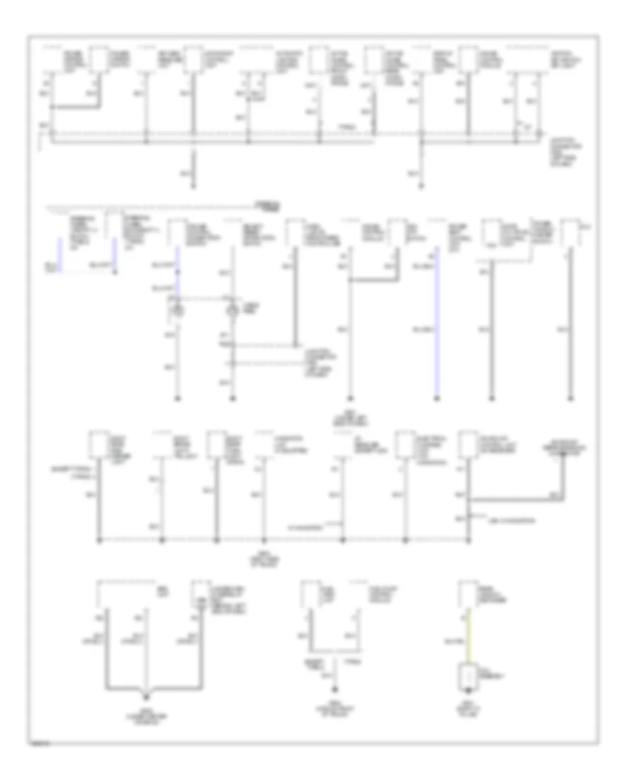 https://portal-diagnostov.com/license.html
Automotive Electricians Portal FZCO
Automotive Electricians Portal FZCO
https://portal-diagnostov.com/license.html
https://portal-diagnostov.com/license.html
Automotive Electricians Portal FZCO
Automotive Electricians Portal FZCOList of elements for Ground Distribution Wiring Diagram (4 of 4) for Acura TL Type S 2007:
- (except type s)
- (type s)
- A/t
- A11
- A22
- A23
- Active noise control front micro- phone
- Active noise control rear micro- phone
- Acuralink control unit (xm receiver)
- Acuralink reprogramming connector
- Automatic lighting control unit
- B10
- B11
- B14
- B15
- Cable reel
- Coil assembly
- Cruise control combination switch
- Dash lights brightness controller
- Display panel control unit
- Dlc
- Door multiplex control unit
- Electrical compass unit (w/o navigation)
- Except type s
- Fuel pump control module
- Fuel tank unit
- G501 (under left side of dash)
- G505 (under center console)
- G603 (middle front of trunk)
- G604 (right side of trunk)
- G801 (right "c" pillar)
- Gauge control module
- Ignition key switch/ key light
- Junction connector c508 (left side of dash)
- Keyless receiver unit
- Mes con
- Moonroof control unit
- Navigation unit (if equipped)
- Pg1
- Power mirror control unit
- Power mirror switch
- Power seat control unit (m/t)
- Power window master switch
- Rear window defogger
- Right brake light/ taillight
- Right rear side marker light
- Right rear turn light signal
- Select/ reset/ information switch
- Srs unit
- Steering wheel
- Steering wheel downshift (-) switch (type s: a/t)
- Steering wheel upshift (+) switch (type s: a/t)
- Type s
- Under-dash fuse/relay box (behind left end of dash)
- Usa: w/ navigation
- Vsa off switch
- W/ navigation
- Xm receiver (except usa)
HEADLIGHTS
Headlights Wiring Diagram, with DRL (1 of 2) for Acura TL Type S 2007
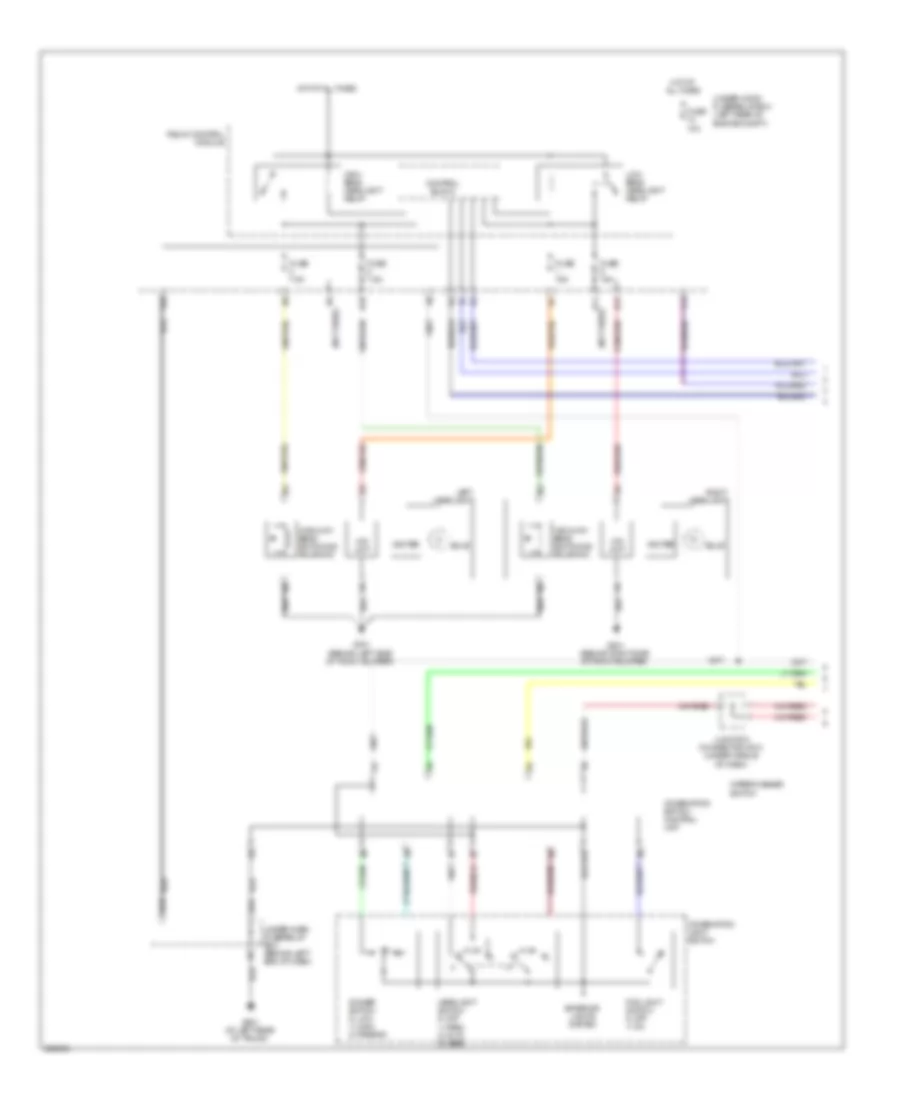 https://portal-diagnostov.com/license.html
Automotive Electricians Portal FZCO
Automotive Electricians Portal FZCO
https://portal-diagnostov.com/license.html
https://portal-diagnostov.com/license.html
Automotive Electricians Portal FZCO
Automotive Electricians Portal FZCOList of elements for Headlights Wiring Diagram, with DRL (1 of 2) for Acura TL Type S 2007:
- (not used)
- B12
- Bulb
- Combination light switch
- Combination switch control unit
- Control block
- Dimmer switch 0) low 1) high 2) passing
- Exterior lights system
- F13
- Fog light switch 0) off 1) on
- Fuse 10a
- Fuse 15a
- Fuse 7.5a
- G201 (behind right side of front bumper)
- G301 (behind left side of front bumper)
- G601 (at left rear of trunk)
- H10
- H11
- H12
- Headlight switch 0) off 1) park 2) auto 3) head
- Hid unit
- High beam headlight relay
- High/low beam switching solenoid
- Hot at all times
- Igniter
- Junction connector c510 (under middle of dash)
- K10
- Left headlight
- Low beam headlight relay
- Relay control module
- Right headlight
- Under-dash fuse/relay box (behind left end of dash)
- Under-hood fuse/relay box (left rear of engine compt)
- Wiper/washer switch
Headlights Wiring Diagram, with DRL (2 of 2) for Acura TL Type S 2007
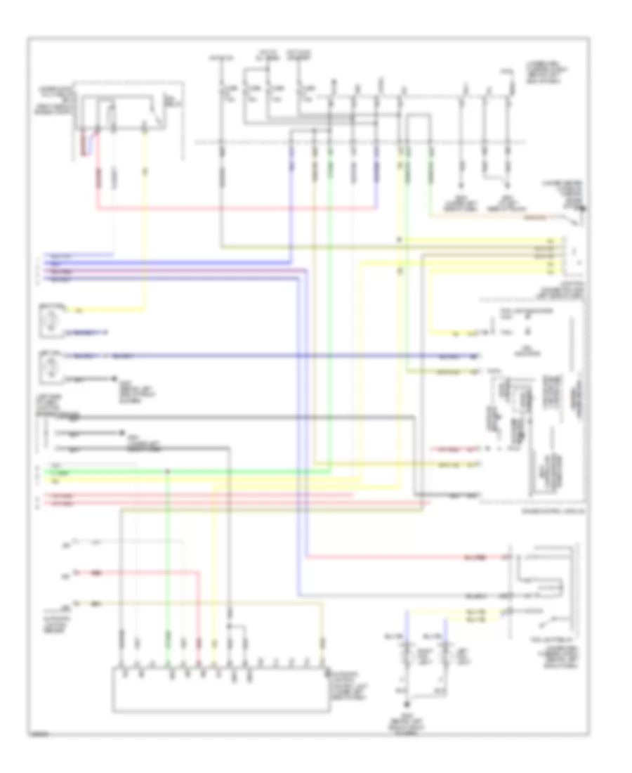 https://portal-diagnostov.com/license.html
Automotive Electricians Portal FZCO
Automotive Electricians Portal FZCO
https://portal-diagnostov.com/license.html
https://portal-diagnostov.com/license.html
Automotive Electricians Portal FZCO
Automotive Electricians Portal FZCOList of elements for Headlights Wiring Diagram, with DRL (2 of 2) for Acura TL Type S 2007:
- (left side of dash) junction connector c508
- (under center console) parking brake switch
- +b drl
- Automatic lighting control unit (under left side of dash)
- Automatic lighting sensor
- B-can
- B/u
- B10
- B11
- B17
- B18
- Bus
- Circuit drive
- Controller circuit/can cpu/fail safe
- D11
- D14
- Drive circuit warning
- Drl indicator
- Drl relay
- Fog light indicator
- Fog light relay
- Fuse 15a
- Fuse 7.5a
- G302 (behind left side of front bumper)
- G501 (under left side of dash)
- G502 (under left side of dash)
- G601 (at left rear of trunk)
- Gauge control module
- Gnd1
- Gnd2
- Hot at all times
- Hot in on
- Hot in on or start
- Ig1
- Ig2
- Indicator high beam
- Indicator lights on
- Junction connector c506 (left side of dash)
- Left drl
- Left fog light
- Micu
- N20
- N28
- N30
- N34
- Red
- Right drl
- Right fog light
- Sg-1
- Sg-2
- Sig
- Sio
- Sip
- Transceiver area network controller body
- Under-dash fuse/relay box (behind left end of dash)
- Under-hood multi-relay box (right side of engine compt)
- Vbu
- X27
- X33
- X34
- X35
Headlights Wiring Diagram, without DRL (1 of 2) for Acura TL Type S 2007
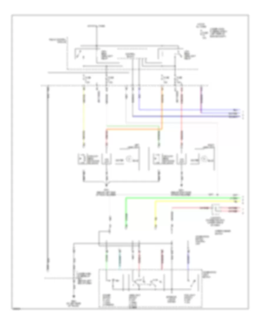 https://portal-diagnostov.com/license.html
Automotive Electricians Portal FZCO
Automotive Electricians Portal FZCO
https://portal-diagnostov.com/license.html
https://portal-diagnostov.com/license.html
Automotive Electricians Portal FZCO
Automotive Electricians Portal FZCOList of elements for Headlights Wiring Diagram, without DRL (1 of 2) for Acura TL Type S 2007:
- (not used)
- B12
- Bulb
- Combination light switch
- Combination switch control unit
- Control block
- Dimmer switch 0) low 1) high 2) passing
- Exterior lights system
- F13
- Fog light switch 0) off 1) on
- Fuse 10a
- Fuse 15a
- Fuse 7.5a
- G201 (behind right side of front bumper)
- G301 (behind left side of front bumper)
- G601 (at left rear of trunk)
- H10
- H11
- H12
- Headlight switch 0) off 1) park 2) auto 3) head
- Hid unit
- High beam headlight relay
- High/low beam switching solenoid
- Hot at all times
- Igniter
- Junction connector c510 (under middle of dash)
- K10
- Left headlight
- Low beam headlight relay
- N18
- N42
- Relay control module
- Right headlight
- Under-dash fuse/relay box (behind left end of dash)
- Under-hood fuse/relay box (left rear of engine compt)
- Wiper/washer switch
Headlights Wiring Diagram, without DRL (2 of 2) for Acura TL Type S 2007
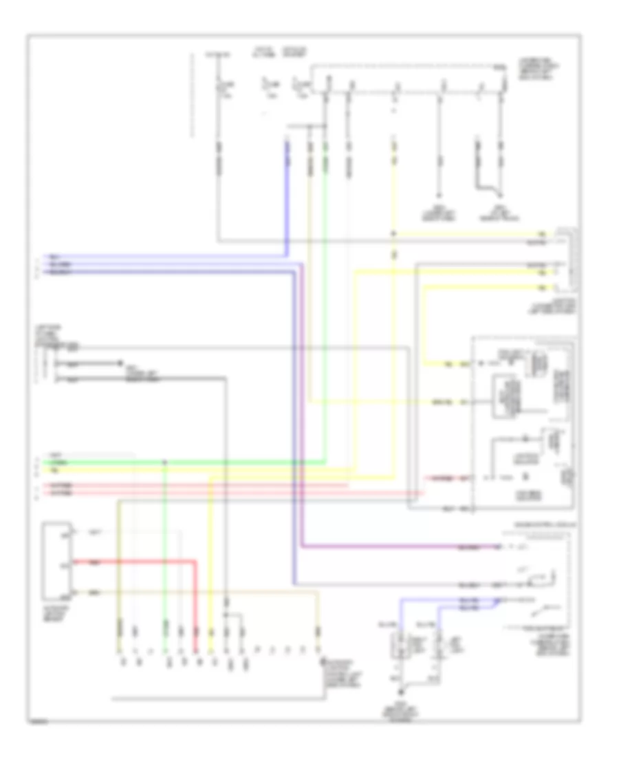 https://portal-diagnostov.com/license.html
Automotive Electricians Portal FZCO
Automotive Electricians Portal FZCO
https://portal-diagnostov.com/license.html
https://portal-diagnostov.com/license.html
Automotive Electricians Portal FZCO
Automotive Electricians Portal FZCOList of elements for Headlights Wiring Diagram, without DRL (2 of 2) for Acura TL Type S 2007:
- (left side of dash) junction connector c508
- Automatic lighting control unit (under left side of dash)
- Automatic lighting sensor
- B-can
- B/u
- B10
- B11
- B17
- B18
- Bus
- Circuit drive
- Circuit drive warning
- Controller body
- Controller circuit/can cpu/fail safe
- D11
- Fog light indicator
- Fog light relay
- Fuse 7.5a
- G302 (behind left side of front bumper)
- G501 (under left side of dash)
- G502 (under left side of dash)
- G601 (at left rear of trunk)
- Gauge control module
- Gnd1
- Gnd2
- High beam indicator
- Hot at all times
- Hot in on
- Hot in on or start
- Ig1
- Ig2
- Junction connector c506 (left side of dash)
- Left fog light
- Lights on indicator
- Micu
- N20
- N28
- Red
- Right fog light
- Sg-1
- Sg-2
- Sig
- Sio
- Sip
- Transceiver area network
- Under-dash fuse/relay box (behind left end of dash)
- Vbu
- X27
- X33
- X34
- X35
HORN
Horn Wiring Diagram for Acura TL Type S 2007
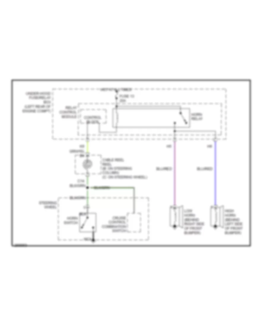 https://portal-diagnostov.com/license.html
Automotive Electricians Portal FZCO
Automotive Electricians Portal FZCO
https://portal-diagnostov.com/license.html
https://portal-diagnostov.com/license.html
Automotive Electricians Portal FZCO
Automotive Electricians Portal FZCOList of elements for Horn Wiring Diagram for Acura TL Type S 2007:
- C14
- Cable reel reel (b: on steering column) (c: on steering wheel)
- Control block
- Cruise control combination switch
- Fuse 13 20a
- High horn (behind left side of front bumper)
- Horn relay
- Horn switch
- Hot at all times
- Low horn (behind right side of front bumper)
- Nca
- Relay control module
- Steering wheel
- Under-hood fuse/relay box (left rear of engine compt)
INSTRUMENT CLUSTER
Instrument Cluster Wiring Diagram (1 of 2) for Acura TL Type S 2007
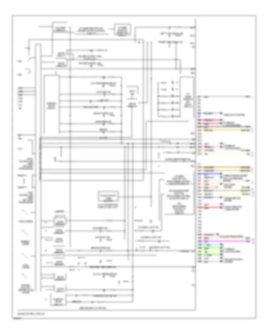 https://portal-diagnostov.com/license.html
Automotive Electricians Portal FZCO
Automotive Electricians Portal FZCO
https://portal-diagnostov.com/license.html
https://portal-diagnostov.com/license.html
Automotive Electricians Portal FZCO
Automotive Electricians Portal FZCOList of elements for Instrument Cluster Wiring Diagram (1 of 2) for Acura TL Type S 2007:
- (canada)
- A/t gear position detection circuit
- A/t gear position ind brightness control & dimming circuit
- A/t gear position ind drive circuit
- A/t gear position ind/ cruise control dimming
- A10
- A11
- A12
- A13
- A14
- A15
- A16
- A17
- A18
- A19
- A20
- A21
- A22
- A23
- A24
- A25
- A26
- A27
- A28
- A29
- A30
- Abs ind
- Anti-lock brakes system
- Anti-theft system
- B10
- B11
- B12
- B13
- B14
- B15
- B16
- B17
- B18
- Beeper
- Body controller area network transceiver
- Brake system ind
- Charging system ind
- Circuit
- Computer data lines system
- Cooling fans system
- Cpu/fail safe circuit/can controller
- Cruise control ind
- Cruise control main switch ind
- Cruise control system
- Dial/ring/pointer/ shift ind brightness control & dimming circuit
- Door & trunk open monitor
- Drive circuit
- Drl ind
- Engine coolant temperature gauge
- Exterior lights system
- Fail safe circuit
- Fast controller area network transceiver
- Fog light ind
- Fuel gauge
- Gauge control module
- Headlights system
- High beam ind
- Immobilizer system ind
- Interior lights system
- Lcd back light ind
- Left turn signal ind
- Lights on ind
- Low fuel ind
- Low oil pressure ind
- Low tire pressure ind
- Mid brightness control & dimming circuit
- Mil ind
- Multi-information display (mid) unit
- Red
- Right turn signal ind
- Seat belt reminder ind
- Shift ind
- Side air bag cut-off ind
- Speedo- meter
- Srs ind
- Tachometer
- Transmissions system
- Vsa activation ind
- Vsa system ind
- Warning drive
- Warning drive circuit
- Wiper/washer system
Instrument Cluster Wiring Diagram (2 of 2) for Acura TL Type S 2007
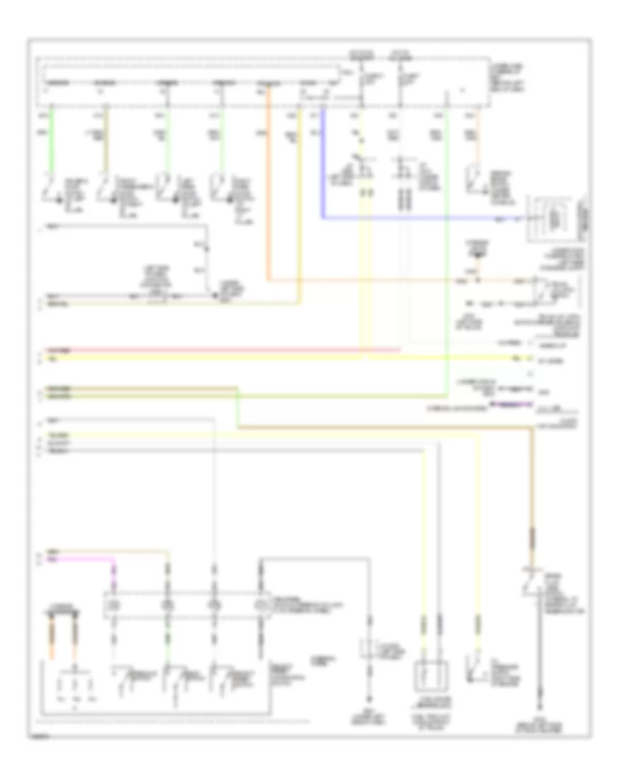 https://portal-diagnostov.com/license.html
Automotive Electricians Portal FZCO
Automotive Electricians Portal FZCO
https://portal-diagnostov.com/license.html
https://portal-diagnostov.com/license.html
Automotive Electricians Portal FZCO
Automotive Electricians Portal FZCOList of elements for Instrument Cluster Wiring Diagram (2 of 2) for Acura TL Type S 2007:
- (left side of dash) junction connector c508
- (under left side of dash) g501
- (under middle of dash) g503
- +b back up
- B-can
- B11
- B12
- B13
- B14
- Brake fluid level switch (integral to brake fluid reservoir cap)
- Cable reel (a & b: on steering column) (c: on steering wheel)
- Clock (w/o navigation)
- Control block
- D11
- Driver's door switch (at left "b" pillar)
- Drswas
- Drswdr
- Drswra
- Drswrd
- E14
- E15
- Front passenger's door switch (at right "b" pillar)
- Fuel gauge sending unit
- Fuel tank unit (middle front of trunk)
- Fuse 21 7.5a
- Fuse 7 7.5a
- G302 (behind left side of front bumper)
- G501 (under left side of dash)
- G701 (left side of trunk)
- Gnd
- H12
- H13
- Hot at all times
- Hot in on or start
- Ig1
- Ig1 meter
- Ill(-) led
- Information switch
- Interior lights system
- J/c c506 (left side of dash)
- J/c c508 (left side of dash)
- J/c c510 (under middle of dash)
- Left rear door switch (at left "c" pillar)
- Micu
- N28
- N30
- N34
- Next switch
- Oil pressure switch (right side of engine)
- P24
- Parking brake switch (under center console)
- Relay control module
- Right rear door switch (at right "c" pillar)
- Select/ reset switch
- Select/ reset/
- Steering wheel
- Trunk lid latch switch
- Trunk lid latch switch/opener solenoid (middle of trunk lid)
- Trunk sw
- Under-dash fuse/relay box (behind left end of dash)
- Under-hood fuse/relay box (left rear of engine compt)
- X34
- X35
INTERIOR LIGHTS
Courtesy Lamps Wiring Diagram for Acura TL Type S 2007
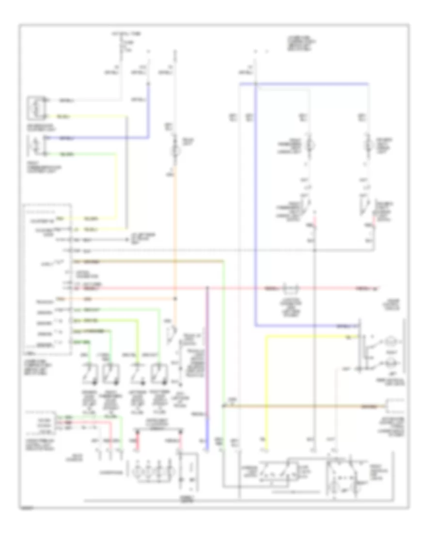 https://portal-diagnostov.com/license.html
Automotive Electricians Portal FZCO
Automotive Electricians Portal FZCO
https://portal-diagnostov.com/license.html
https://portal-diagnostov.com/license.html
Automotive Electricians Portal FZCO
Automotive Electricians Portal FZCOList of elements for Courtesy Lamps Wiring Diagram for Acura TL Type S 2007:
- (at left rear of trunk) g601
- (not used)
- (option connector)
- 0) off
- 1) auto 2) on
- Active noise control unit (type s) (under middle of dash)
- Ambient lights
- Courtesy as
- Courtesy door
- Driver's door courtesy light
- Driver's door switch (at left "b" pillar)
- Driver's vanity mirror light
- Driver's vanity mirror light switch
- Drswas
- Drswdr
- Drswra
- Drswrd
- E14
- E15
- Front individual map lights
- Front passenger's door courtesy light
- Front passenger's door switch (at right "b" pillar)
- Front passenger's vanity mirror light
- Front passenger's vanity mirror light switch
- Fuse 7.5a
- G701 (left side of trunk)
- Gauge control module
- H12
- H13
- Hands freelink control unit (front of roof)
- Hot at all times
- Instrument illumination circuit
- Interior light switch
- Intr lt
- J12
- Junction connector c506 (left side of dash)
- Left
- Left rear door switch (at left "c" pillar)
- Mic sh
- Mic sig+
- Mic sig-
- Microphone
- Micu
- N15
- P24
- P30
- Rear individual map lights
- Red
- Right
- Right rear door switch (at right "c" pillar)
- Roof console
- Trunk lid latch switch
- Trunk lid latch switch/ opener solenoid (middle of trunk lid)
- Trunk light
- Trunk sw
- Type s
- Under-dash fuse/relay box (behind left end of dash)
Entry Light Timer Wiring Diagram for Acura TL Type S 2007
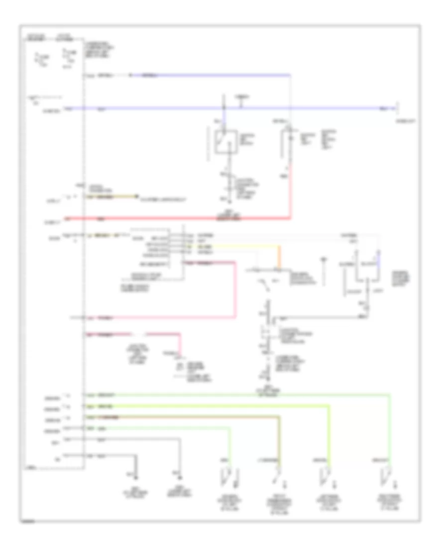 https://portal-diagnostov.com/license.html
Automotive Electricians Portal FZCO
Automotive Electricians Portal FZCO
https://portal-diagnostov.com/license.html
https://portal-diagnostov.com/license.html
Automotive Electricians Portal FZCO
Automotive Electricians Portal FZCOList of elements for Entry Light Timer Wiring Diagram for Acura TL Type S 2007:
- (option connector)
- A16
- A18
- A19
- B-can
- Canada
- Courtesy lamps circuit
- Door multiplex control unit
- Driver's door key cylinder switch
- Driver's door lock knob switch
- Driver's door switch (at left "b" pillar)
- Drswas
- Drswdr
- Drswra
- Drswrd
- E14
- E15
- Front passenger's door switch (at right "b" pillar)
- Fuse 7.5a
- G501 (under left side of dash)
- G502 (under left side of dash)
- G601 (at left rear of trunk)
- H12
- H13
- Hot at all times
- Hot in on or start
- Ig key lt
- Ig key sw
- Ig1
- Ignition key light
- Ignition key switch
- Ignition key switch/ key light
- Imoes unit
- Intr lt
- J10
- Junction connector c507 (left side of dash)
- Junction connector c508 (left side of dash)
- Junction connector c635 (in left front door)
- Key
- Key lock
- Key unlock
- Keyless entry
- Keyless receiver unit (under left side of dash)
- Knob lock
- Knob unlock
- Left rear door switch (at left "c" pillar)
- Lock
- Micu
- N15
- P13
- Power window master switch
- Red
- Right rear door switch (at right "c" pillar)
- Sg-1
- Sig out
- Under-dash fuse/relay box (behind left end of dash)
- Unlock
Instrument Illumination Wiring Diagram (1 of 3) for Acura TL Type S 2007
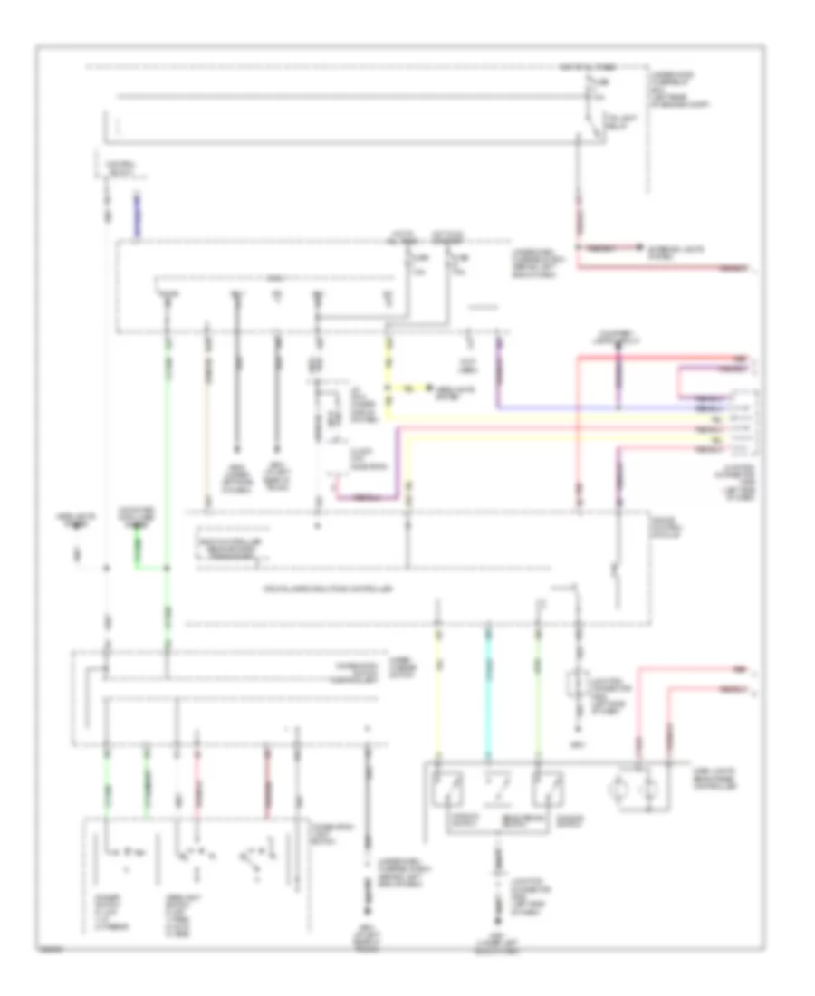 https://portal-diagnostov.com/license.html
Automotive Electricians Portal FZCO
Automotive Electricians Portal FZCO
https://portal-diagnostov.com/license.html
https://portal-diagnostov.com/license.html
Automotive Electricians Portal FZCO
Automotive Electricians Portal FZCOList of elements for Instrument Illumination Wiring Diagram (1 of 3) for Acura TL Type S 2007:
- (not
- A25
- A26
- A27
- B-can
- B10
- B11
- B12
- B17
- B18
- Body controller area network transceiver
- Brightening switch
- Clock (w/o navigation)
- Combination light switch
- Combination switch control unit
- Computer data lines system
- Control block
- Courtesy lamps circuit
- Cpu/fail safe circuit/can controller
- D11
- Dash lights brightness controller
- Dimmer switch 0) low 1) hi 2) passing
- Dimming switch
- Exterior lights system
- Fuse 10a
- Fuse 7.5a
- G501
- G501 (under left side of dash)
- G502 (under left side of dash)
- G601 (at left rear of trunk)
- Gauge control module
- Headlight switch 0) off 1) park 2) auto 3) head
- Headlights system
- Hot at all times
- Hot in on or start
- Ig1
- J/c c510 (under middle of dash)
- J12
- Junction connector c506 (left side of dash)
- Junction connector c508 (left side of dash)
- Maximum switch
- Micu
- N28
- N42
- Red
- Sg-1
- Taillight relay
- Under-dash fuse/relay box (behind left end of dash)
- Under-hood fuse/relay box (left rear of engine compt)
- Used)
- Vbu
- Wiper/ washer switch
- X27
- X34
- X35
Instrument Illumination Wiring Diagram (2 of 3) for Acura TL Type S 2007
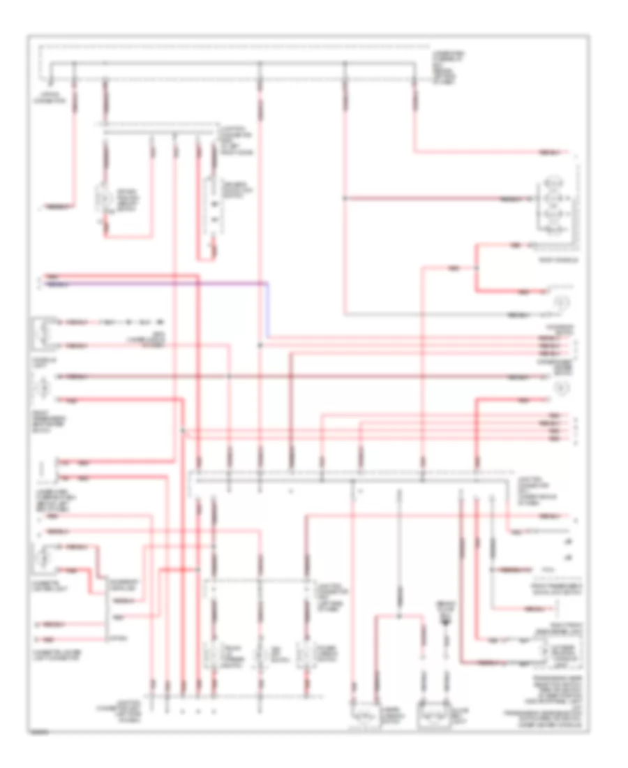 https://portal-diagnostov.com/license.html
Automotive Electricians Portal FZCO
Automotive Electricians Portal FZCO
https://portal-diagnostov.com/license.html
https://portal-diagnostov.com/license.html
Automotive Electricians Portal FZCO
Automotive Electricians Portal FZCOList of elements for Instrument Illumination Wiring Diagram (2 of 3) for Acura TL Type S 2007:
- (behind glove box) g506
- (option connector)
- A/t gear position console light
- Accessory installed
- Cigarette lighter light
- Cigarette lighter light connector
- Console light
- Driver's door lock switch
- Driver's seat heater switch
- Driving position memory switch x3
- Front passenger's door lock switch
- Front passenger's seat heater switch
- G503 (under middle of dash)
- Glove box light
- Hazard warning switch
- J15
- J19
- Junction connector c507 (left side of dash)
- Junction connector c511 (under middle of dash)
- Junction connector c635 (in left front door)
- Moonroof switch
- N31
- Option
- Power mirror switch
- Red
- Right front side marker light
- Roof console
- Transmission gear selection switch/ park pin switch/ a/t gear position indicator panel light (a/t) (transmission gear selection switch/park pin switch: under center console)
- Trunk lid opener switch
- Under-dash fuse/relay box (behind left end of dash)
- Vsa off switch
Instrument Illumination Wiring Diagram (3 of 3) for Acura TL Type S 2007
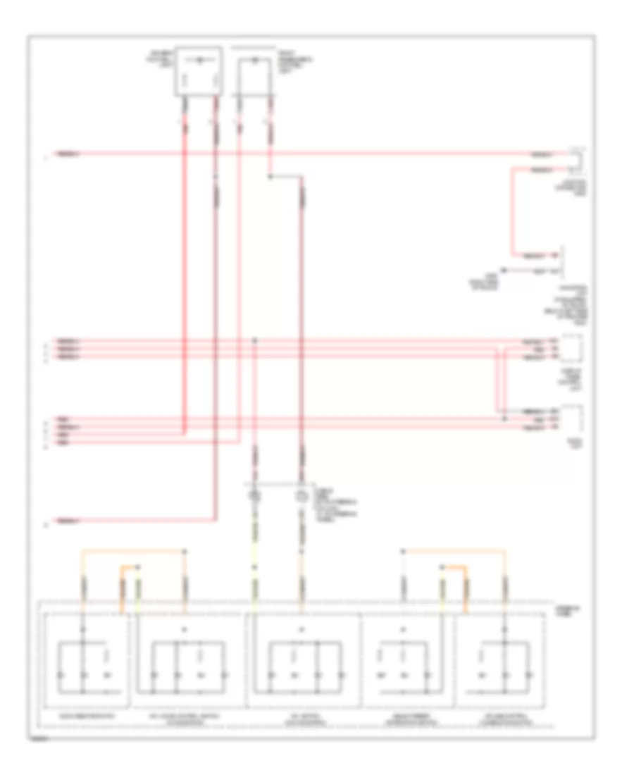 https://portal-diagnostov.com/license.html
Automotive Electricians Portal FZCO
Automotive Electricians Portal FZCO
https://portal-diagnostov.com/license.html
https://portal-diagnostov.com/license.html
Automotive Electricians Portal FZCO
Automotive Electricians Portal FZCOList of elements for Instrument Illumination Wiring Diagram (3 of 3) for Acura TL Type S 2007:
- A15
- A19
- Audio remote switch
- Audio unit
- B16
- B17
- Cable reel (b: on steering column) (c: on steering wheel)
- Cruise control combination switch
- Display panel control unit
- Driver's footwell light
- Front passenger's footwell light
- G604 (right side of trunk)
- Hfl switch (w/o navigation)
- Hfl-voice control switch (w/ navigation)
- Junction connector c602
- Navigation unit (if equipped) (in trunk, below left side of package tray)
- Red
- Select/reset/ information switch
- Steering wheel
MEMORY SYSTEMS
Driver"s Memory Seat Wiring Diagram (1 of 2) for Acura TL Type S 2007
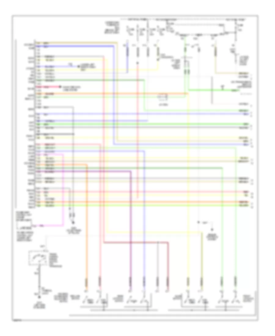 https://portal-diagnostov.com/license.html
Automotive Electricians Portal FZCO
Automotive Electricians Portal FZCO
https://portal-diagnostov.com/license.html
https://portal-diagnostov.com/license.html
Automotive Electricians Portal FZCO
Automotive Electricians Portal FZCOList of elements for Driver"s Memory Seat Wiring Diagram (1 of 2) for Acura TL Type S 2007:
- (on transmission) back-up light switch
- (under left side of dash) g501
- A/t
- A10
- A11
- A12
- A13
- A14
- A15
- A16
- A17
- A18
- A19
- A20
- Atp-r
- B-can
- Back lt
- Back lt-
- Back- ward
- C10
- C11
- C12
- Computer data lines system
- Down
- Driver's power seat adjustment switch
- Engine controls system
- F11
- F13
- Fhdn
- Fhm+
- Fhm-
- Fhse
- Fhup
- For- ward
- Front up-down switch
- Fuse 15a
- Fuse 20a
- Fuse 7.5a
- G101 (left side of engine)
- G601 (at left rear of trunk)
- Hot at all times
- Hot in on or start
- Ig1
- J/c c506 (left side of dash)
- J/c c602
- J/c c635 (in left front door)
- M/t
- Micu
- Mt gnd
- P20
- Pgnd 1
- Pgnd2
- Pnk
- Power mirror control unit (under left side of dash)
- Power seat control unit (under driver's seat)
- Rear up-down switch
- Recline switch
- Red
- Refw
- Rem+
- Rem-
- Rerw
- Rese
- Rhdn
- Rhm+
- Rhm-
- Rhse
- Rhup
- S2 (thermal joint)
- Scom
- Seg 2
- Seg1
- Sgnd
- Slfw
- Slide switch
- Slm+
- Slm-
- Slrw
- Slse
- Trans- mission range switch (on transaxle)
- Uart
- Uart bus
- Under-dash fuse/relay box (behind left end of dash)
- Vbu
- Vcc sen1
- Vcc sen2
- Vmp1
- Vmp2
- W/o navigation
Driver"s Memory Seat Wiring Diagram (2 of 2) for Acura TL Type S 2007
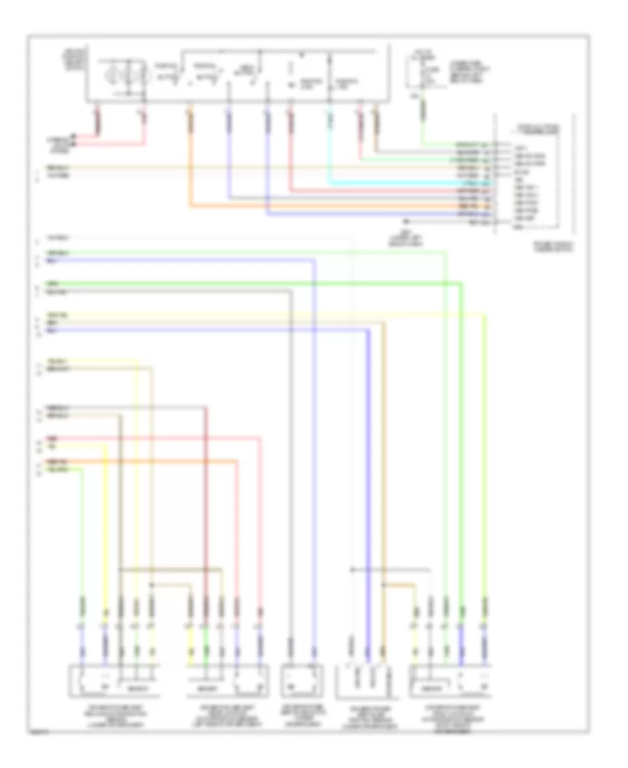 https://portal-diagnostov.com/license.html
Automotive Electricians Portal FZCO
Automotive Electricians Portal FZCO
https://portal-diagnostov.com/license.html
https://portal-diagnostov.com/license.html
Automotive Electricians Portal FZCO
Automotive Electricians Portal FZCOList of elements for Driver"s Memory Seat Wiring Diagram (2 of 2) for Acura TL Type S 2007:
- A11
- A12
- A13
- A22
- B-can
- B11
- B14
- Door multiplex control unit
- Driver's power seat front up-down motor/position sensor (right side of driver's seat)
- Driver's power seat rear up-down motor/position sensor (left side of driver's seat)
- Driver's power seat recline motor/position sensor (under driver's seat)
- Driver's power seat slide motor (under driver's seat)
- Driver's power seat slide position sensor (under driver's seat)
- Driving position memory switch
- Fuse 30a
- G501 (under left side of dash)
- Ground
- Hot at all times
- Interior lights system
- Mem ind 1
- Mem ind 2
- Mem pos1
- Mem pos2
- Mem set
- Mem sw gnd
- Mem sw pwr
- Memo button
- Pg1
- Pos out
- Position 1 ind
- Position 2 ind
- Position button
- Power window master switch
- Red
- Reference
- Sensor
- Under-dash fuse/relay box (behind left end of dash)
- Vbu
- Vmp 1
- X24
Memory Mirrors Wiring Diagram for Acura TL Type S 2007
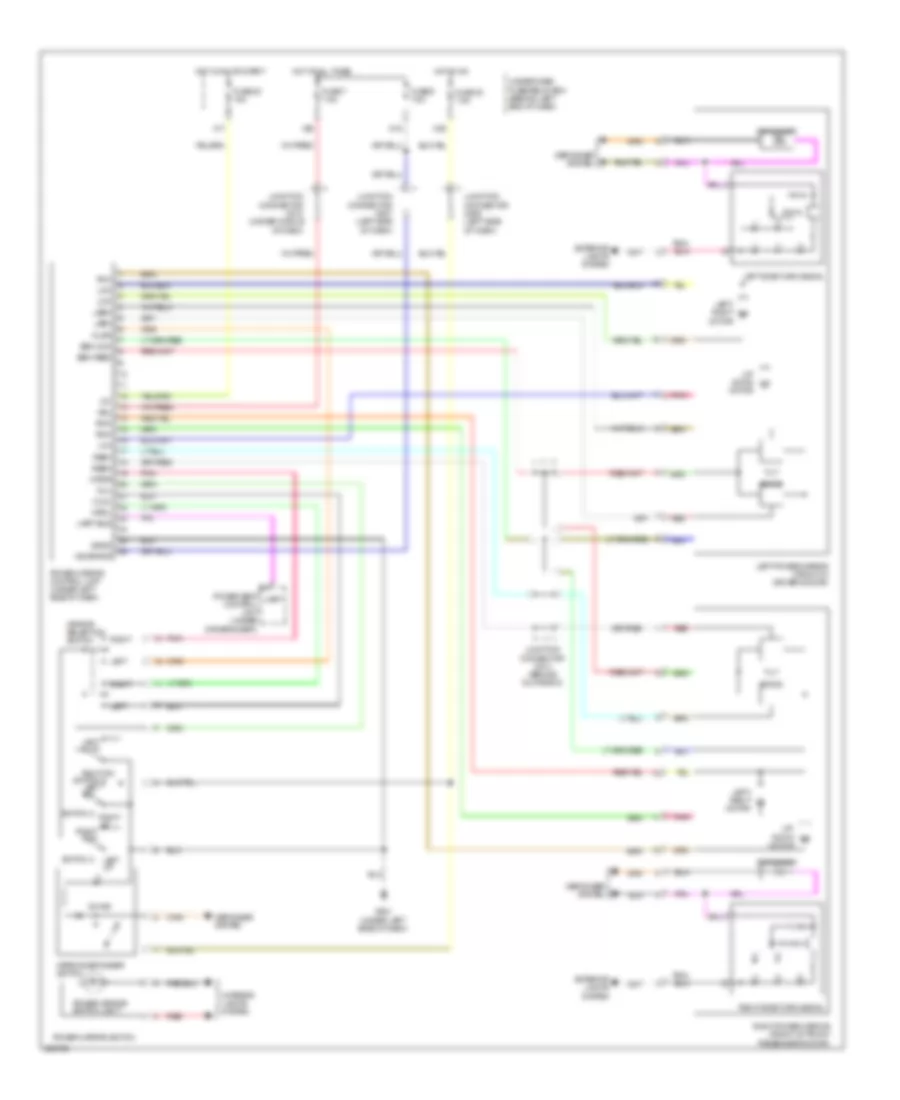 https://portal-diagnostov.com/license.html
Automotive Electricians Portal FZCO
Automotive Electricians Portal FZCO
https://portal-diagnostov.com/license.html
https://portal-diagnostov.com/license.html
Automotive Electricians Portal FZCO
Automotive Electricians Portal FZCOList of elements for Memory Mirrors Wiring Diagram for Acura TL Type S 2007:
- +b mirror
- Defogger
- Defogger system
- Exterior lights system
- Fuse 20 15a
- Fuse 30 7.5a
- Fuse 6 7.5a
- Fuse 7 7.5a
- G501 (under left side of dash)
- Hot at all times
- Hot in on
- Hot in on or start
- Ig1
- Interior lights system
- Junction connector c506 (left side of dash)
- Junction connector c507 (left side of dash)
- Junction connector c510 (under middle of dash)
- Junction connector c513 (behind glove box)
- Left
- Left dn
- Left power mirror (front of driver's door)
- Left side turn signal
- Left up
- Left/ right motor
- Lmc
- Lmh
- Lmv
- Lseh
- Lsev
- Mirror defogger switch
- Mirror selection switch
- Mldl
- Mldr
- Mrdl
- Mrdr
- Mul
- N15
- N20
- On ind
- Pnk
- Power mirror control unit (under left side of dash)
- Power mirror switch
- Power mirror switch light
- Power seat control unit (under driver's seat)
- Red
- Right
- Right dn
- Right power mirror (front of front passenger's door)
- Right side turn signal
- Right up right dn
- Rmc
- Rmh
- Rmv
- Rseh
- Rsev
- Sen com
- Sen feed
- Sgnd
- Swing
- Switch 1
- Switch 2
- Switch 3
- Tilt
- Uart
- Uart bus
- Under-dash fuse/relay box (behind left end of dash)
- Up/ down motor
- Vbu
- X17
- X35
NAVIGATION
Home Link Remote Control Wiring Diagram for Acura TL Type S 2007
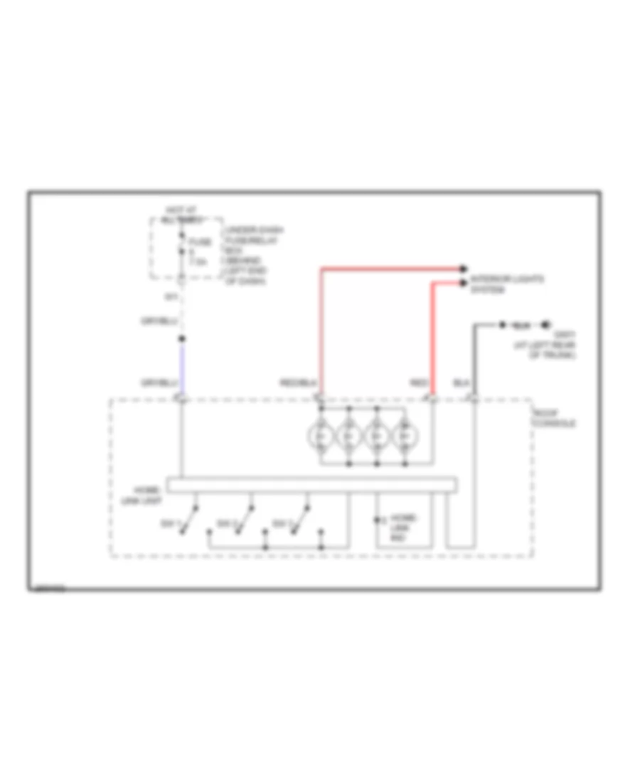 https://portal-diagnostov.com/license.html
Automotive Electricians Portal FZCO
Automotive Electricians Portal FZCO
https://portal-diagnostov.com/license.html
https://portal-diagnostov.com/license.html
Automotive Electricians Portal FZCO
Automotive Electricians Portal FZCOList of elements for Home Link Remote Control Wiring Diagram for Acura TL Type S 2007:
- Fuse 7.5a
- G601 (at left rear of trunk)
- Home- link ind
- Home- link unit
- Hot at all times
- Interior lights system
- Red
- Roof console
- Sw 1
- Sw 2
- Sw 3
- Under-dash fuse/relay box (behind left end of dash)
Navigation Wiring Diagram, Canada (1 of 3) for Acura TL Type S 2007
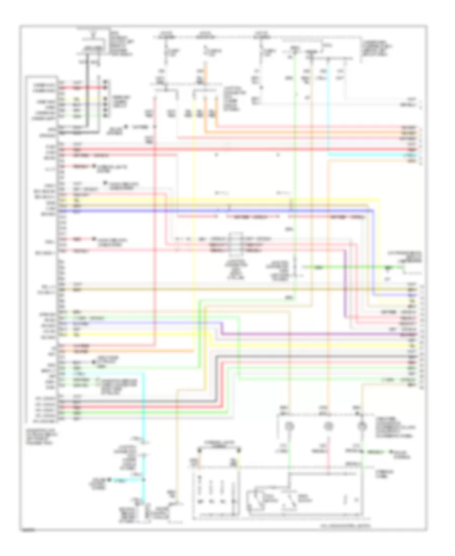 https://portal-diagnostov.com/license.html
Automotive Electricians Portal FZCO
Automotive Electricians Portal FZCO
https://portal-diagnostov.com/license.html
https://portal-diagnostov.com/license.html
Automotive Electricians Portal FZCO
Automotive Electricians Portal FZCOList of elements for Navigation Wiring Diagram, Canada (1 of 3) for Acura TL Type S 2007:
- (on transmission) back-up light switch
- (right side of trunk)
- (right side of trunk) g604
- A/t
- A10
- A11
- A12
- A13
- A14
- A15
- A16
- A17
- A18
- A19
- A20
- Acc
- Amplifier
- B sig
- B-can
- B10
- B11
- B12
- B13
- B14
- B18
- Back lt
- Back switch
- C sig
- C10
- C18
- C20
- Cable reel (connetor b: on steering column) (connetor c: on steering wheel)
- Camera adpt
- Camera gnd
- Camera sh
- Camera vcc
- Can-h
- Can-l
- Computer data lines system
- Cruise control system
- Diag+
- Diag-
- Ecm/pcm (behind center of dash)
- Ecu bus (+)
- Ecu bus (-)
- Ecu bus sh
- Fuse 32 7.5a
- Fuse 6 7.5a
- Fuse 7 7.5a
- G sig
- Gauge control module
- Gnd
- Gps
- Gps antenna (on top left rear of package tray shelf)
- Gps gnd
- Hfl comm1
- Hfl comm2
- Hfl comm3
- Hfl comm4
- Hfl commsh
- Hfl-voice control switch
- Hot at all times
- Hot in acc or on
- Ill (+)
- Interior lights system
- Junction connector c506 (left side of dash)
- Junction connector c510 (under middle of dash)
- Junction connector c512 (under middle of dash)
- Junction connector c603 (right c-pillar)
- M/t
- Mic gnd
- Mic sh
- Mic sig (+)
- Micu
- N22
- N28
- N36
- Navigation service check connector
- Navigation unit (in trunk, below left side of package tray)
- Nca
- R sig
- Rearview camera circuit
- Red
- Rg gnd
- Rg l (+)
- Rg sh
- Sig gnd
- Sig sh
- Sound systems
- Steering wheel
- Strg sw
- Talk switch
- Under-dash fuse/relay box (behind left end of dash)
- Video
- Video gnd
- Vsp
- Vssout
- X18
- X35
Navigation Wiring Diagram, Canada (2 of 3) for Acura TL Type S 2007
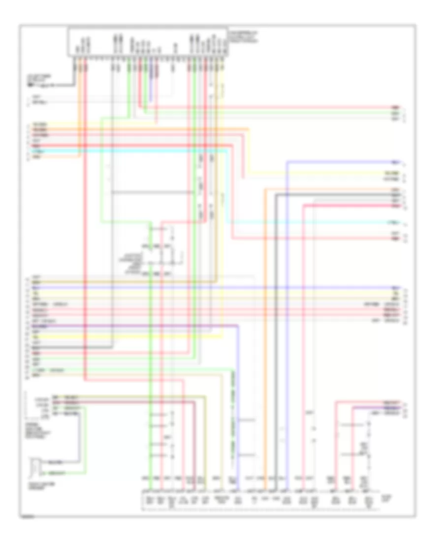 https://portal-diagnostov.com/license.html
Automotive Electricians Portal FZCO
Automotive Electricians Portal FZCO
https://portal-diagnostov.com/license.html
https://portal-diagnostov.com/license.html
Automotive Electricians Portal FZCO
Automotive Electricians Portal FZCOList of elements for Navigation Wiring Diagram, Canada (2 of 3) for Acura TL Type S 2007:
- (at left rear of trunk) g601
- A11
- A12
- A13
- Acc
- Aud bus sh
- Aud bus+
- Aud bus-
- Audio unit
- B-can
- B10
- B15
- C10
- C11
- C12
- C13
- C14
- C21
- C27
- C28
- C29
- Ctr sp+
- Ctr sp-
- Ctr-
- Ecu bus sh
- Ecu bus+
- Ecu bus-
- Front center speaker
- Gnd
- Handsfreelink control unit (front of roof)
- Hfl comm1
- Hfl comm2
- Hfl comm3
- Hfl comm4
- Hfl mute
- Hfl sh
- Ims0
- Ims1
- Junction connector c652 (front of roof)
- Mic out sh
- Mic out+
- Mic out-
- Mic sh
- Mic sig+
- Mic sig-
- Pnk
- Red
- Remote gnd
- Rg gnd
- Rg l+
- Stereo amplifier (behind right kick panel)
- Strg sw
- Telm sig sh
- Telm sig+
- Telm sig-
Navigation Wiring Diagram, Canada (3 of 3) for Acura TL Type S 2007
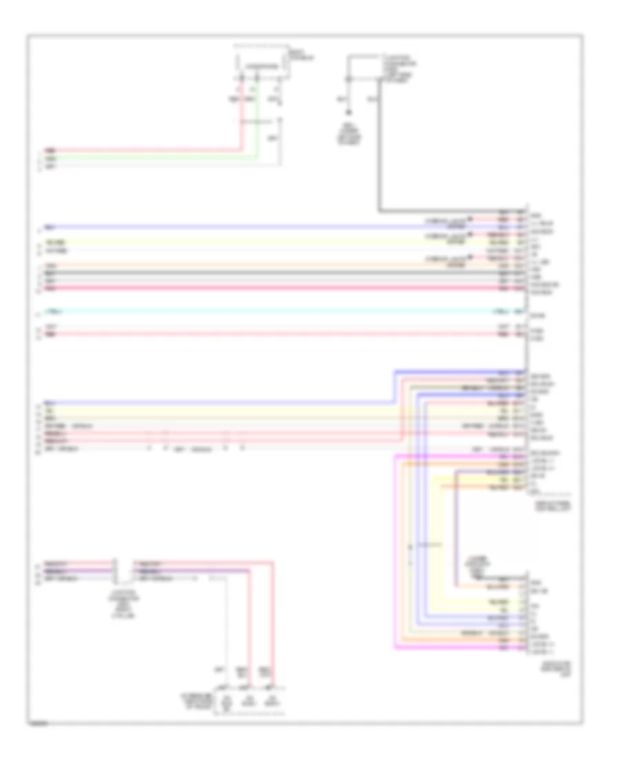 https://portal-diagnostov.com/license.html
Automotive Electricians Portal FZCO
Automotive Electricians Portal FZCO
https://portal-diagnostov.com/license.html
https://portal-diagnostov.com/license.html
Automotive Electricians Portal FZCO
Automotive Electricians Portal FZCOList of elements for Navigation Wiring Diagram, Canada (3 of 3) for Acura TL Type S 2007:
- (under middle of dash) g503
- A10
- A15
- A16
- A17
- A18
- A19
- A22
- Acc
- Aud bus sh
- Aud bus+
- Aud bus-
- Audio-hvac sub display unit
- B sig
- B-can
- C sig
- Display panel control unit
- E10
- E11
- E12
- E13
- E14
- E15
- E18
- E19
- E20
- E21
- E22
- Ecu bus sh
- Ecu bus+
- Ecu bus-
- G sig
- G501 (under left side of dash)
- Ga bus sh
- Ga bus(+)
- Ga bus(-)
- Gnd
- Ill-
- Ill- bulb
- Ill- led
- Ims0
- Ims1
- Inh
- Interior lights system
- Junction connector c508 (left side of dash)
- Junction connector c603 (right c-pillar)
- Lcd bl (+)
- Lcd bl (-)
- Microphone
- Pnk
- R sig
- Red
- Roof console
- Sd (+b)
- Sd +b
- Sh gnd
- Sig gnd
- Sig sh
- Xm receiver (right side of trunk)
Navigation Wiring Diagram, USA (1 of 3) for Acura TL Type S 2007
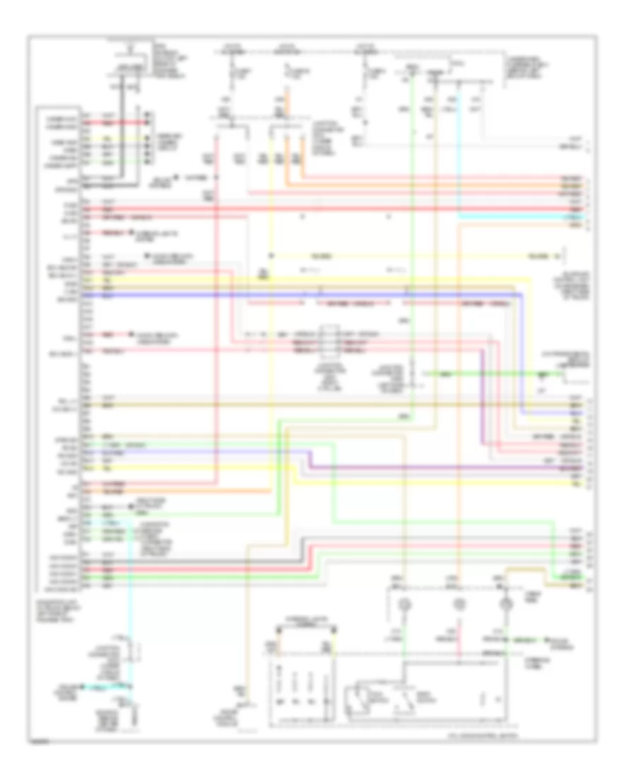 https://portal-diagnostov.com/license.html
Automotive Electricians Portal FZCO
Automotive Electricians Portal FZCO
https://portal-diagnostov.com/license.html
https://portal-diagnostov.com/license.html
Automotive Electricians Portal FZCO
Automotive Electricians Portal FZCOList of elements for Navigation Wiring Diagram, USA (1 of 3) for Acura TL Type S 2007:
- (on transmission) back-up light switch
- (right side of trunk) g604
- A/t
- A10
- A11
- A12
- A13
- A14
- A15
- A16
- A17
- A18
- A19
- A20
- Acc
- Acuralink control unit (xm receiver) (right side of trunk)
- Amplifier
- B sig
- B-can
- B10
- B11
- B12
- B13
- B14
- B18
- Back lt
- Back switch
- C sig
- C10
- C18
- C20
- Cable reel
- Camera adpt
- Camera gnd
- Camera sh
- Camera vcc
- Can-h
- Can-l
- Check connector (right side of trunk)
- Computer data lines system
- Cruise control system
- Diag+
- Diag-
- Ecm/pcm (behind center of dash)
- Ecu bus (+)
- Ecu bus (-)
- Ecu bus sh
- Fuse 32 7.5a
- Fuse 6 7.5a
- Fuse 7 7.5a
- G sig
- Gauge control module
- Gnd
- Gps
- Gps antenna (on top left rear of package tray shelf)
- Gps gnd
- Hfl-voice control switch
- Hot at all times
- Hot in acc or on
- Ill (+)
- Interior lights system
- Junction connector c506 (left side of dash)
- Junction connector c510 (under middle of dash)
- Junction connector c512 (under middle of dash)
- Junction connector c603 (right c-pillar)
- M/t
- Mic gnd
- Mic sh
- Mic sig (+)
- Micu
- N22
- N28
- N36
- Nav comm sh
- Nav comm1
- Nav comm2
- Nav comm3
- Nav comm4
- Navigation service
- Navigation unit (in trunk, below left side of package tray)
- Nca
- R sig
- Rearview camera circuit
- Red
- Rg gnd
- Rg l (+)
- Rg sh
- Sig gnd
- Sig sh
- Sound systems
- Steering wheel
- Strg sw
- Talk switch
- Under-dash fuse/relay box (behind left end of dash)
- Video
- Video gnd
- Vsp
- Vssout
- X18
- X35
Navigation Wiring Diagram, USA (2 of 3) for Acura TL Type S 2007
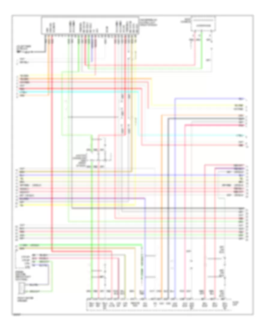 https://portal-diagnostov.com/license.html
Automotive Electricians Portal FZCO
Automotive Electricians Portal FZCO
https://portal-diagnostov.com/license.html
https://portal-diagnostov.com/license.html
Automotive Electricians Portal FZCO
Automotive Electricians Portal FZCOList of elements for Navigation Wiring Diagram, USA (2 of 3) for Acura TL Type S 2007:
- (at left rear of trunk) g601
- A11
- A12
- A13
- Acc
- Aud bus sh
- Aud bus+
- Aud bus-
- Audio unit
- B-can
- B10
- B15
- C10
- C11
- C12
- C13
- C14
- C21
- C27
- C28
- C29
- Ctr sp+
- Ctr sp-
- Ctr+
- Ctr-
- Ecu bus sh
- Ecu bus+
- Ecu bus-
- Front center speaker
- Gnd
- Handsfreelink control unit (front of roof)
- Hfl comm1
- Hfl comm2
- Hfl comm3
- Hfl comm4
- Hfl mute
- Hfl sh
- Ims0
- Ims1
- Junction connector c652 (front of roof)
- Mic out sh
- Mic out+
- Mic out-
- Mic sig sh
- Mic sig(+)
- Mic sig(-)
- Microphone
- Pnk
- Red
- Remote gnd
- Rg gnd
- Rg l+
- Roof console
- Stereo amplifier (behind right kick panel)
- Strg sw
- Telm sig sh
- Telm sig(-)
- Telm sig+
- Telm sig-
Navigation Wiring Diagram, USA (3 of 3) for Acura TL Type S 2007
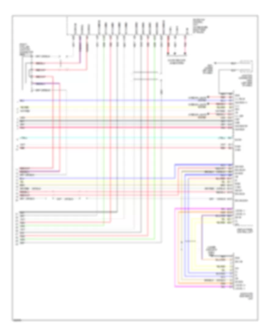 https://portal-diagnostov.com/license.html
Automotive Electricians Portal FZCO
Automotive Electricians Portal FZCO
https://portal-diagnostov.com/license.html
https://portal-diagnostov.com/license.html
Automotive Electricians Portal FZCO
Automotive Electricians Portal FZCOList of elements for Navigation Wiring Diagram, USA (3 of 3) for Acura TL Type S 2007:
- (right c-pillar) junction connector c603
- (under middle of dash) g503
- A10
- A13
- A14
- A15
- A16
- A17
- A18
- A19
- A22
- Acc
- Acuralink control unit (xm receiver) (right side of trunk)
- Aud bus (+)
- Aud bus sh
- Aud bus-
- Audio-hvac sub display unit
- B sig
- B-can
- C sig
- C15
- C16
- Computer data lines system
- Display panel control unit
- E10
- E11
- E12
- E13
- E14
- E15
- E18
- E19
- E20
- E21
- E22
- Ecu bus sh
- Ecu bus+
- Ecu bus-
- F-can h
- F-can l
- G sig
- G501 (under left side of dash)
- Ga bus sh
- Ga bus(+)
- Ga bus(-)
- Gnd
- Hft comm sh
- Hft comm1
- Hft comm2
- Hft comm3
- Hft comm4
- Ill+
- Ill- bulb
- Ill- led
- Ims0
- Ims1
- Inh
- Interior lights system
- Junction connector c508 (left side of dash)
- Lcd bl (+)
- Lcd bl (-)
- Nav comm sh
- Nav comm1
- Nav comm2
- Nav comm3
- Nav comm4
- Pnk
- R sig
- Red
- Sd (+b)
- Sd +b
- Sh gnd
- Sig gnd
- Sig sh
Parking Assistant Wiring Diagram, Accessory for Acura TL Type S 2007
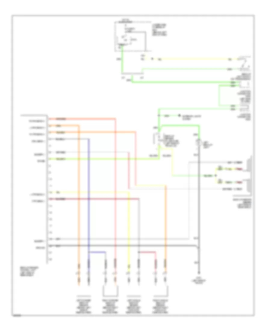 https://portal-diagnostov.com/license.html
Automotive Electricians Portal FZCO
Automotive Electricians Portal FZCO
https://portal-diagnostov.com/license.html
https://portal-diagnostov.com/license.html
Automotive Electricians Portal FZCO
Automotive Electricians Portal FZCOList of elements for Parking Assistant Wiring Diagram, Accessory for Acura TL Type S 2007:
- A/t
- Back lt
- Back-up light switch (on transmission)
- Back-up sensor beeper (left side of rear shelf)
- Back-up sensor control unit (left side of rear shelf)
- Back-up sensor in-line fuse (left side of trunk lid)
- Buzzer (-)
- Crn sens (-)
- Ctr sens (-)
- Exterior lights system
- Fuse 21 7.5a
- G701 (left side of trunk)
- Ground
- Hot in on or start
- Ig1
- Junction connector c506 (left side of dash)
- Junction connector c602
- L crn sens (+)
- L ctr sens (+)
- Left back-up light
- Left corner back-up sensor (behind left side of rear bumper)
- Left middle back-up sensor (behind left middle of rear bumper)
- M/t
- Micu
- Power
- R crn sens (+)
- R ctr sens (+)
- Red
- Right corner back-up sensor (behind right side of rear bumper)
- Right middle back-up sensor (behind right middle of rear bumper)
- Under-dash fuse/relay box (behind left end of dash)
- X34
Rear Camera Wiring Diagram for Acura TL Type S 2007
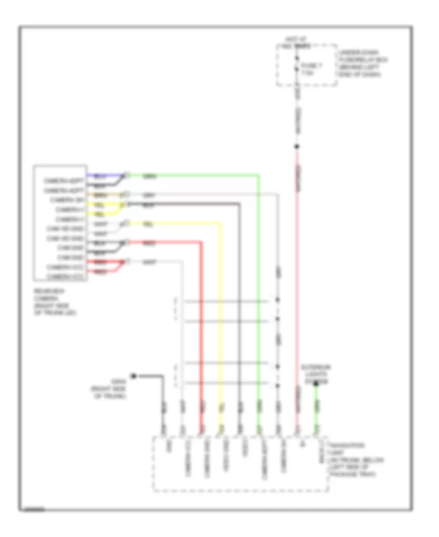 https://portal-diagnostov.com/license.html
Automotive Electricians Portal FZCO
Automotive Electricians Portal FZCO
https://portal-diagnostov.com/license.html
https://portal-diagnostov.com/license.html
Automotive Electricians Portal FZCO
Automotive Electricians Portal FZCOList of elements for Rear Camera Wiring Diagram for Acura TL Type S 2007:
- Back lt
- Cam gnd
- Cam vid gnd
- Camera adpt
- Camera gnd
- Camera sh
- Camera v
- Camera vcc
- Exterior lights system
- Fuse 7 7.5a
- G604 (right side of trunk)
- Gnd
- Hot at all times
- Navigation unit (in trunk, below left side of package tray)
- Rearview camera (right side of trunk lid)
- Red
- Under-dash fuse/relay box (behind left end of dash)
- Video
- Video gnd
- X35
PASSIVE RESTRAINTS
Passive Restraints Wiring Diagram for Acura TL Type S 2007
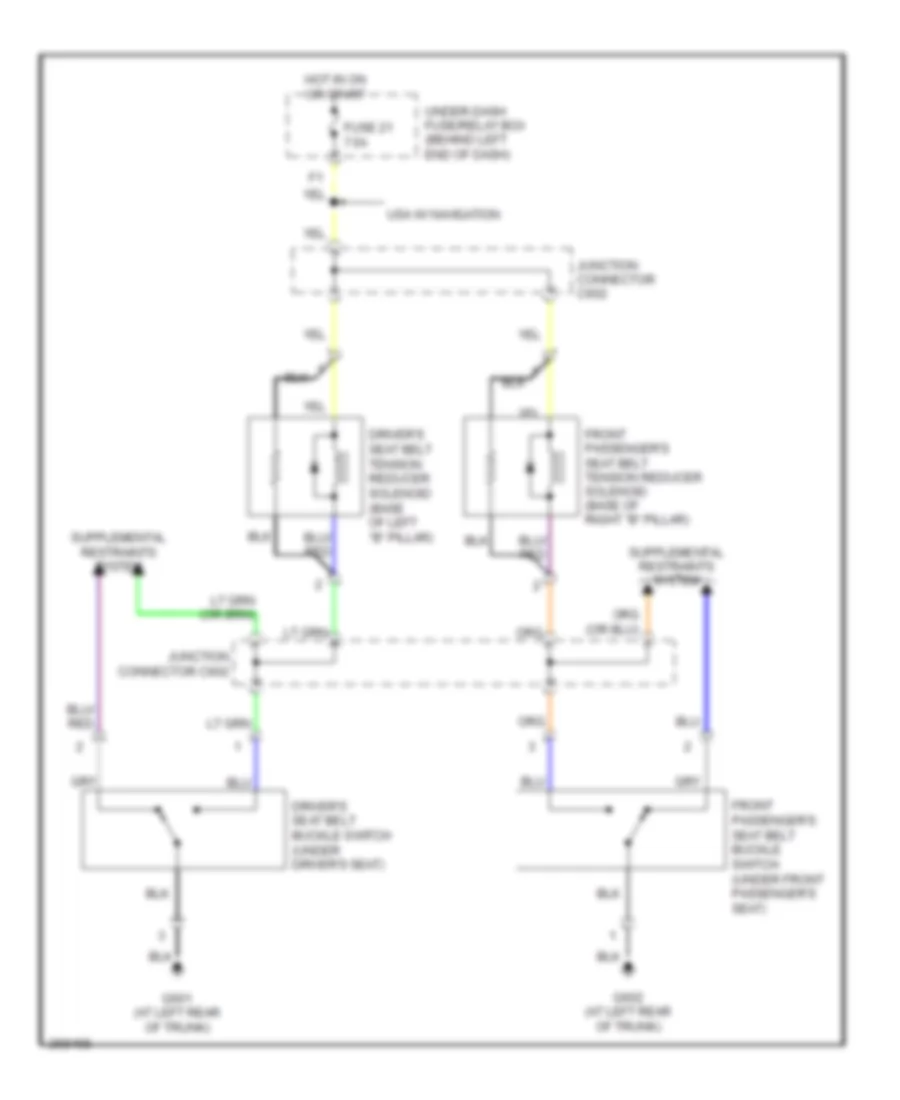 https://portal-diagnostov.com/license.html
Automotive Electricians Portal FZCO
Automotive Electricians Portal FZCO
https://portal-diagnostov.com/license.html
https://portal-diagnostov.com/license.html
Automotive Electricians Portal FZCO
Automotive Electricians Portal FZCOList of elements for Passive Restraints Wiring Diagram for Acura TL Type S 2007:
- Driver's seat belt buckle switch (under driver's seat)
- Driver's seat belt tension reducer solenoid (base of left "b" pillar)
- Front passenger's seat belt buckle switch (under front passenger's seat)
- Front passenger's seat belt tension reducer solenoid (base of right "b" pillar)
- Fuse 21 7.5a
- G601 (at left rear of trunk)
- G602 (at left rear of trunk)
- Hot in on or start
- Junction connector c602
- Under-dash fuse/relay box (behind left end of dash)
- Usa w/ navigation
POWER DISTRIBUTION
Power Distribution Wiring Diagram (1 of 5) for Acura TL Type S 2007
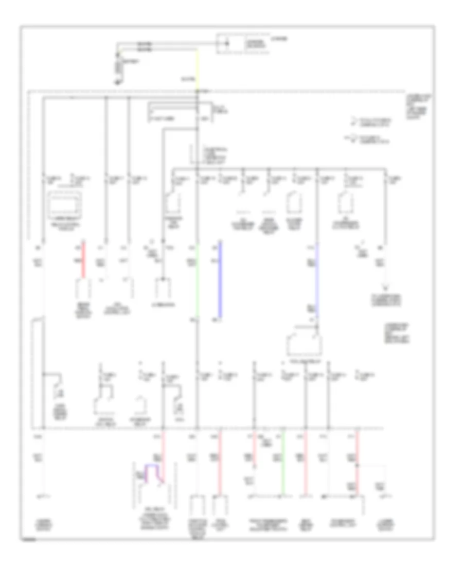 https://portal-diagnostov.com/license.html
Automotive Electricians Portal FZCO
Automotive Electricians Portal FZCO
https://portal-diagnostov.com/license.html
https://portal-diagnostov.com/license.html
Automotive Electricians Portal FZCO
Automotive Electricians Portal FZCOList of elements for Power Distribution Wiring Diagram (1 of 5) for Acura TL Type S 2007:
- (not used)
- +b drl
- +b haz
- 120a
- A/c compressor clutch relay
- A/c condenser fan relay
- A/f sensor relay
- Alternator
- Battery
- Blower motor relay
- Brake pedal position switch
- D14
- D17
- Drl relay
- Electrical load detector (eld) unit
- F11
- F13
- Fog light relay
- Front passenger's power seat adjustment switch
- Fuse 1 15a
- Fuse 10 10a
- Fuse 11 30a
- Fuse 12 7.5a
- Fuse 13 20a
- Fuse 14 20a
- Fuse 14 40a
- Fuse 15 20a
- Fuse 16 15a
- Fuse 16 20a
- Fuse 17 20a
- Fuse 17 30a
- Fuse 18 40a
- Fuse 19 40a
- Fuse 2 15a
- Fuse 20 40a
- Fuse 21 40a
- Fuse 3 15a
- Fuse 4 15a
- Fuse 8 15a
- Fuse 9 30a
- Hazard warning switch
- Horn relay
- Ignition coil relay
- Lumbar support switch
- Micu
- Multi- fuse 22
- N40
- N45
- Power seat control unit
- Radiator fan relay
- Rear window defogger relay
- Red
- Relay control module
- Seat heater relay
- Starter
- Starter solenoid
- T101
- T102
- Throttle actuator control module relay
- To fuse 15 (diagram 3 of 5)
- To multi-fuse 23 (diagram 2 of 5)
- To under-dash fuse/relay box (diagram 5 of 5)
- Tpms control unit
- Turn signal/ hazard relay
- Under-dash fuse/relay box (behind left end of dash)
- Under-hood fuse/relay box (left rear of engine compt)
- Under-hood multi-relay box (right side of engine compt)
- Vsa modulator control unit
- X12
- X23
- X26
Power Distribution Wiring Diagram (2 of 5) for Acura TL Type S 2007
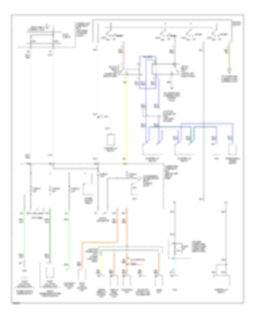 https://portal-diagnostov.com/license.html
Automotive Electricians Portal FZCO
Automotive Electricians Portal FZCO
https://portal-diagnostov.com/license.html
https://portal-diagnostov.com/license.html
Automotive Electricians Portal FZCO
Automotive Electricians Portal FZCOList of elements for Power Distribution Wiring Diagram (2 of 5) for Acura TL Type S 2007:
- (diagram 1 of 5)
- (not used)
- 50a
- 7.5a
- A/t
- Acc
- Acc cut relay (a/t) (under left side of dash)
- Acuralink control unit (xm receiver)
- Audio unit
- Auxiliary under-dash fuse holder (under left side of dash)
- B11
- Display panel control unit
- Door multiplex control unit
- E21
- From fuse 12 a
- Front passenger's power window switch
- Fuse
- Fuse 26 30a
- Fuse 27 30a
- Fuse 28 20a
- Fuse 32 7.5a
- Fuse 33 7.5a
- Hands freelink control unit
- Ig2 cut relay (a/t) (under left side of dash)
- Ignition switch
- Junction connector c508 (left side of dash)
- Junction connector c510 (under middle of dash)
- Lock
- M/t
- Micu
- Moonroof control unit
- Multi- fuse 23
- N12
- N36
- N39
- Navigation unit
- Option connector
- Pcm
- Power window master switch
- Power window relay
- Shift lock solenoid (a/t)
- Start
- Starter cut relay 1
- Starter cut relay 2
- To accessory power socket relay (diagram 5 0f 5)
- To under-dash fuse/relay box (diagram 3 of 5)
- To under-dash fuse/relay box (diagram 4 of 5)
- Transmission range switch
- Under-dash fuse/relay box (behind left end of dash)
- Under-hood fuse/relay box (left rear of engine compt)
- Usa
- Vmp1
- W/ navigation
- X14
- X24
- X37
- X39
Power Distribution Wiring Diagram (3 of 5) for Acura TL Type S 2007
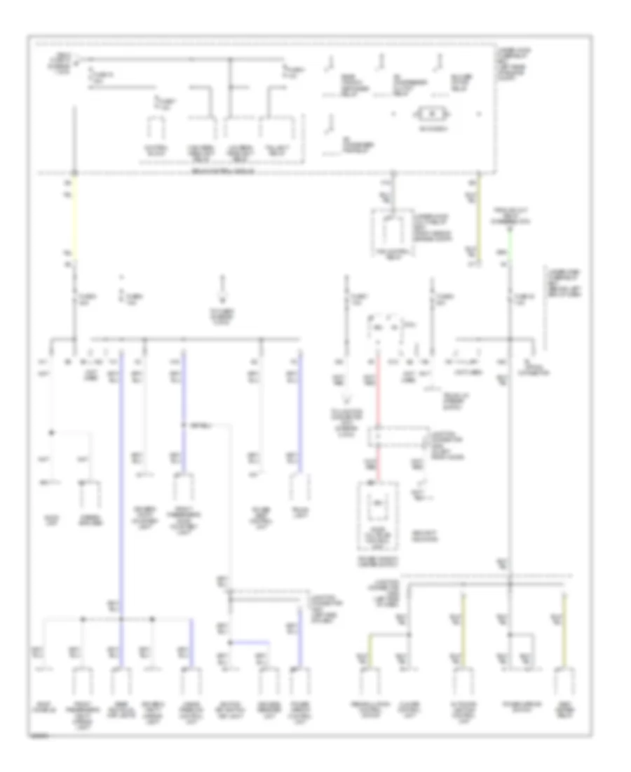 https://portal-diagnostov.com/license.html
Automotive Electricians Portal FZCO
Automotive Electricians Portal FZCO
https://portal-diagnostov.com/license.html
https://portal-diagnostov.com/license.html
Automotive Electricians Portal FZCO
Automotive Electricians Portal FZCOList of elements for Power Distribution Wiring Diagram (3 of 5) for Acura TL Type S 2007:
- (not used)
- 10a
- 7.5a
- A/c compressor clutch relay
- A/c condenser fan relay
- A/c diode a
- A10
- A11
- Audio unit
- Automatic lighting control unit
- Blower motor relay
- Climate control unit
- Control block
- D12
- Door multiplex control unit
- Driver's door courtesy light
- Driver's vanity mirror light
- F19
- Fan control relay
- From fuse 12 b (diagram 1 of 5)
- From ig2 cut relay (diagram 2 of 5)
- Front passenger's door courtesy light
- Front passenger's vanity mirror light
- Fuse 15 40a
- Fuse 30 7.5a
- Fuse 4
- Fuse 5 20a
- Fuse 6 7.5a
- Fuse 7
- Fuse 7 7.5a
- Fuse 8 20a
- Hands freelink control unit
- High beam headlight relay
- Ignition key switch/ key light
- Junction connector c506 (left side of dash)
- Junction connector c507 (left side of dash)
- Junction connector c635 (in left front door)
- Keyless receiver unit
- Low beam headlight relay
- Micu
- N11
- N15
- N20
- Option connector
- Power mirror control unit
- Power mirror switch
- Power seat control unit
- Power window master switch
- Rear individual map lights
- Rear window defogger relay
- Recirculation control motor
- Relay control module
- Roof console
- Seat heater relay
- Security indicator
- Stereo amplifier
- Taillight relay
- To fuse 9 (diagram 5 of 5)
- To junction connector c510 (diagram 5 of 5)
- Trunk lid opener switch
- Trunk light
- Under-dash fuse/relay box (behind left end of dash)
- Under-hood fuse/relay box (left rear of engine compt)
- Under-hood multi-relay box (right side of engine compt)
- Vbu
- X22
- X35
Power Distribution Wiring Diagram (4 of 5) for Acura TL Type S 2007
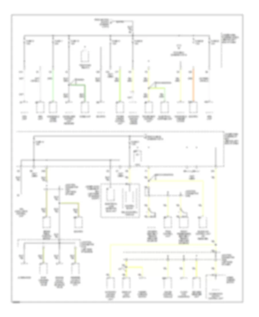 https://portal-diagnostov.com/license.html
Automotive Electricians Portal FZCO
Automotive Electricians Portal FZCO
https://portal-diagnostov.com/license.html
https://portal-diagnostov.com/license.html
Automotive Electricians Portal FZCO
Automotive Electricians Portal FZCOList of elements for Power Distribution Wiring Diagram (4 of 5) for Acura TL Type S 2007:
- (not used)
- A10
- A12
- A17
- A18
- Acuralink control unit (xm receiver)
- Alternator
- Automatic dimming inside mirror
- Automatic lighting control unit
- B18
- Back-up light switch
- Brake pedal position switch
- Canada
- Clock (w/o navigation)
- Combination switch control unit
- Control block
- D12
- Driver's seat belt tension reducer solenoid
- Ecm/pcm
- Electrical compass unit
- Electrical load detector (eld) unit
- Engine mount control solenoid valve
- Evap canister purge valve
- From fuse 20 (diagram 4 of 5)
- From ignition switch d (diagram 2 of 5)
- Front passenger's seat belt tension reducer solenoid
- Fuse 10 7.5a
- Fuse 11 30a
- Fuse 18 15a
- Fuse 19 15a
- Fuse 20 15a
- Fuse 21 7.5a
- Fuse 22 10a
- Fuse 29 7.5a
- Fuse 31 7.5a
- Gauge control module
- Hazard warning switch
- Ig1
- Immobilizer control unit- receiver
- Imoes unit
- Junction connector c105 (left side of engine)
- Junction connector c506 (left side of dash)
- Junction connector c507 (left side of dash)
- Junction connector c602
- Keyless receiver unit
- M/t
- Micu
- N29
- N41
- Ods unit
- Pgm-fi main relay 2
- Power mirror control unit
- Power seat control unit
- Relay control module
- Reverse lockout solenoid (m/t)
- Srs unit
- To fuse 21 (diagram 4 of 5)
- Tpms control unit
- Under-dash fuse/relay box (behind left end of dash)
- Under-hood fuse/relay box (left rear of engine compt)
- Usa w/ navigation
- Vsa modulator control unit
- W/o navigation
- Windshield washer motor
- Windshield wiper motor
- Wiper/ washer switch
- X16
- X17
- X20
- X34
- X38
Power Distribution Wiring Diagram (5 of 5) for Acura TL Type S 2007
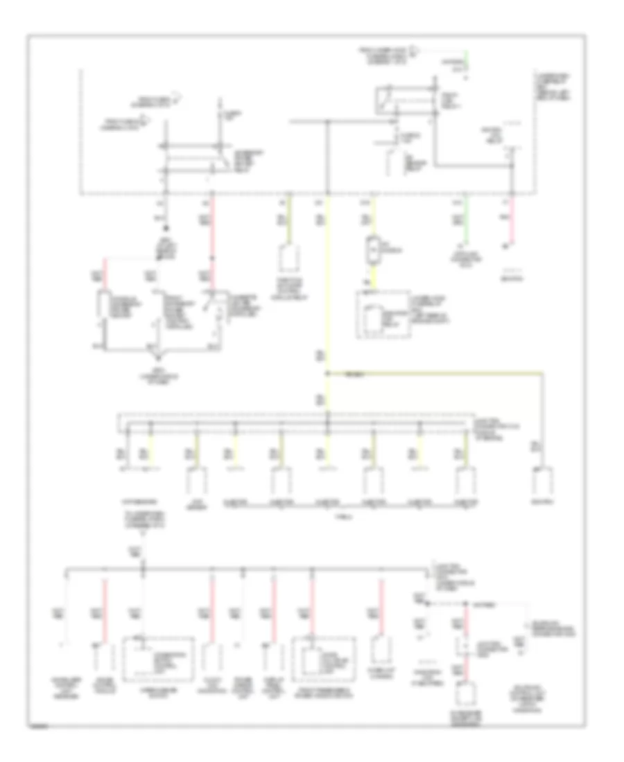 https://portal-diagnostov.com/license.html
Automotive Electricians Portal FZCO
Automotive Electricians Portal FZCO
https://portal-diagnostov.com/license.html
https://portal-diagnostov.com/license.html
Automotive Electricians Portal FZCO
Automotive Electricians Portal FZCOList of elements for Power Distribution Wiring Diagram (5 of 5) for Acura TL Type S 2007:
- A/c diode b
- A/f sensor relay
- A10
- Accessory power socket relay
- Acuralink control unit (xm receiver) (usa w/ navigation)
- Acuralink reprogramming connector c832
- B17
- Cigarette lighter (accessory installed)
- Ckp sensors
- Clock (w/o navigation)
- Cmp sensor
- Combination switch control unit
- Console accessory power socket
- D10
- D16
- Data link connector (dlc)
- Display panel control unit
- Door multiplex control unit
- Ecm/pcm
- From fuse 32 f (diagram 2 of 5)
- From fuse 6 g (diagram 3 of 5)
- From under-hood fuse/relay box (diagram 1 of 5)
- Front accessory power socket (factory installed)
- Front passenger's power window switch
- Fuse 23 7.5a
- Fuse 9 15a
- G503 (under middle of dash)
- G601 (at left rear of trunk)
- Gauge control module
- Ignition coil relay
- Immobilizer control unit- receiver
- Imoes unit (canada)
- Injector
- Junction connector c104 (middle of engine)
- Junction connector c510 (under middle of dash)
- Junction connector c602
- N10
- Navigation unit (if equipped)
- Pgm-fi main relay 1
- Pnk
- Power mirror control unit
- Radiator fan relay
- Throttle actuator control module relay
- To under-dash fuse/relay box (diagram 3 of 5)
- Type s
- Under-dash fuse/relay box (behind left end of dash)
- Under-hood fuse/relay box (left rear of engine compt)
- Wiper/washer switch
- X31
- Xm receiver (except usa navigation)
POWER DOOR LOCKS
Power Door Locks Wiring Diagram (1 of 2) for Acura TL Type S 2007
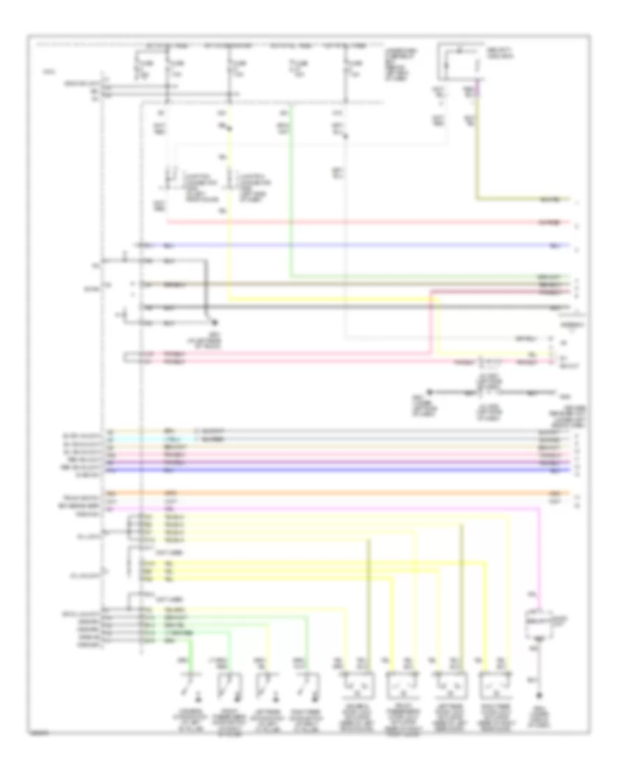 https://portal-diagnostov.com/license.html
Automotive Electricians Portal FZCO
Automotive Electricians Portal FZCO
https://portal-diagnostov.com/license.html
https://portal-diagnostov.com/license.html
Automotive Electricians Portal FZCO
Automotive Electricians Portal FZCOList of elements for Power Door Locks Wiring Diagram (1 of 2) for Acura TL Type S 2007:
- (not used)
- +b door lock
- A20
- Antenna
- Audio unit
- B-can
- D/l lock
- D/l unlock
- D11
- Dr d/l unlock
- Driver's door lock actuator (rear of left front door)
- Driver's door switch (at left "b" pillar)
- Drswas
- Drswdr
- Drswra
- Drswrd
- E10
- E14
- E15
- Front passenger's door lock actuator (rear of right front door)
- Front passenger's door switch (at right "b" pillar)
- Fuse 20a
- Fuse 30a
- Fuse 7.5a
- G501 (under left side of dash)
- G504 (under middle of dash)
- G601 (at left rear of trunk)
- Gnd
- H10
- H12
- H13
- Hot at all times
- Hot in on or start
- Ig key sw
- Ig1
- J/c c507 (left side of dash)
- J/c c508 (left side of dash)
- J10
- Junction connector c506 (left side of dash)
- Junction connector c635 (in left front door)
- K11
- K12
- Keyless buzzer
- Keyless receiver unit (under left side of dash)
- Left rear door lock actuator (rear of left rear door)
- Left rear door switch (at left "c" pillar)
- Micu
- N15
- P13
- P24
- P25
- Q14
- Radio sw
- Rem as lock
- Rem as unlock
- Right rear door lock actuator (rear of right rear door)
- Right rear door switch (at right "c" pillar)
- Security
- Security indicator
- Sig out
- Sil as unlock
- Sil ra unlock
- Sil rd unlock
- Trunk switch
- Under-dash fuse/relay box (behind left end of dash)
- Vbu
- X24
- X34
Power Door Locks Wiring Diagram (2 of 2) for Acura TL Type S 2007
 https://portal-diagnostov.com/license.html
Automotive Electricians Portal FZCO
Automotive Electricians Portal FZCO
https://portal-diagnostov.com/license.html
https://portal-diagnostov.com/license.html
Automotive Electricians Portal FZCO
Automotive Electricians Portal FZCOList of elements for Power Door Locks Wiring Diagram (2 of 2) for Acura TL Type S 2007:
- (a/t)
- (m/t)
- A10
- A14
- A15
- A16
- A18
- A19
- B-can
- B11
- B14
- Control block
- Door multiplex control unit
- Driver's door key cylinder switch
- Driver's door lock knob switch
- Driver's door lock switch
- Front passenger's door lock knob switch
- Front passenger's door lock switch
- Fuse 10a
- Fuse 20a
- Fuse 7.5a
- G301 (behind left side of front bumper)
- G302 (behind left side of front bumper)
- G501 (under left side of dash)
- G506 (behind glove box)
- G601 (at left rear of trunk)
- G602 (at left rear of trunk)
- G701 (left side of trunk)
- H13
- H14
- High horn (behind left side of front bumper)
- Horn relay
- Horns system
- Hot at all times
- Ignition key switch
- Ignition key switch/key light
- Interior lights system
- Junction connector c508 (left side of dash)
- Junction connector c635 (in left front door)
- Key lock
- Key unlock
- Keyless buzzer (behind left front fender)
- Keyless entry
- Knob lock
- Knob unlock
- Left rear door lock knob switch
- Lock
- Low horn (behind right side of front bumper)
- Pg1
- Pnk
- Power window master switch
- Red
- Relay control module
- Right rear door lock knob switch
- Security hood switch (behind middle of front bumper)
- Security ind
- Sw lock
- Sw unlock
- Taillight relay
- Trunk lid latch switch/ opener solenoid (middle of trunk lid)
- Trunk light
- Under-hood fuse/relay box (left rear of engine compt)
- Unlock
- Vbu
- Vmp1
POWER MIRRORS
Automatic Day/Night Mirror Wiring Diagram, A/T for Acura TL Type S 2007
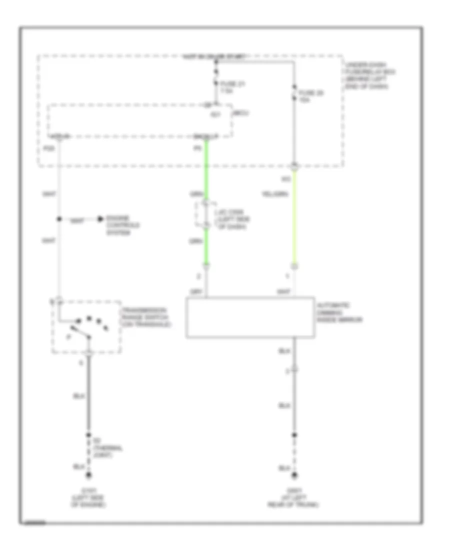 https://portal-diagnostov.com/license.html
Automotive Electricians Portal FZCO
Automotive Electricians Portal FZCO
https://portal-diagnostov.com/license.html
https://portal-diagnostov.com/license.html
Automotive Electricians Portal FZCO
Automotive Electricians Portal FZCOList of elements for Automatic Day/Night Mirror Wiring Diagram, A/T for Acura TL Type S 2007:
- Atp-r
- Automatic dimming inside mirror
- Back lt
- Engine controls system
- Fuse 20 15a
- Fuse 21 7.5a
- G101 (left side of engine)
- G601 (at left rear of trunk)
- Hot in on or start
- Ig1
- J/c c506 (left side of dash)
- Micu
- P20
- S2 (thermal joint)
- Transmission range switch (on transaxle)
- Under-dash fuse/relay box (behind left end of dash)
Automatic Day/Night Mirror Wiring Diagram, M/T for Acura TL Type S 2007
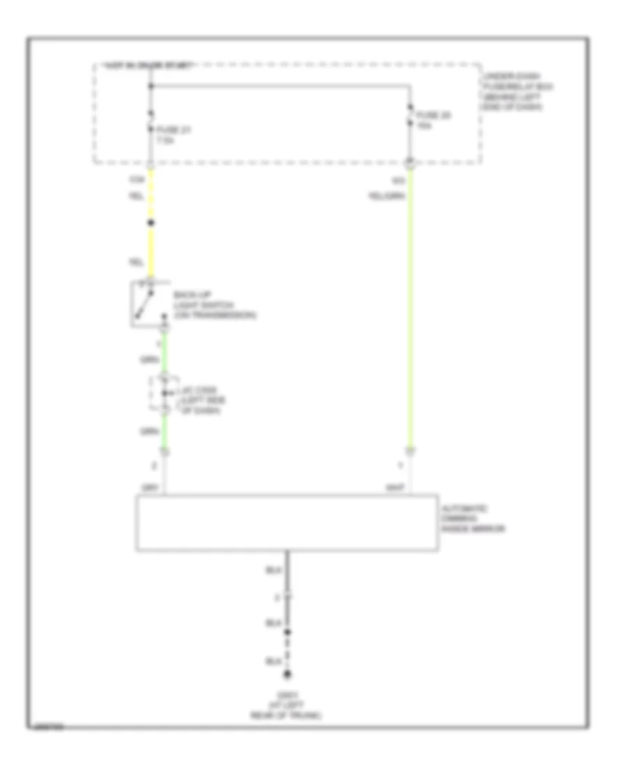 https://portal-diagnostov.com/license.html
Automotive Electricians Portal FZCO
Automotive Electricians Portal FZCO
https://portal-diagnostov.com/license.html
https://portal-diagnostov.com/license.html
Automotive Electricians Portal FZCO
Automotive Electricians Portal FZCOList of elements for Automatic Day/Night Mirror Wiring Diagram, M/T for Acura TL Type S 2007:
- Automatic dimming inside mirror
- Back-up light switch (on transmission)
- Fuse 20 15a
- Fuse 21 7.5a
- G601 (at left rear of trunk)
- Hot in on or start
- J/c c506 (left side of dash)
- Under-dash fuse/relay box (behind left end of dash)
- X34
POWER SEATS
Driver"s Lumbar Wiring Diagram for Acura TL Type S 2007
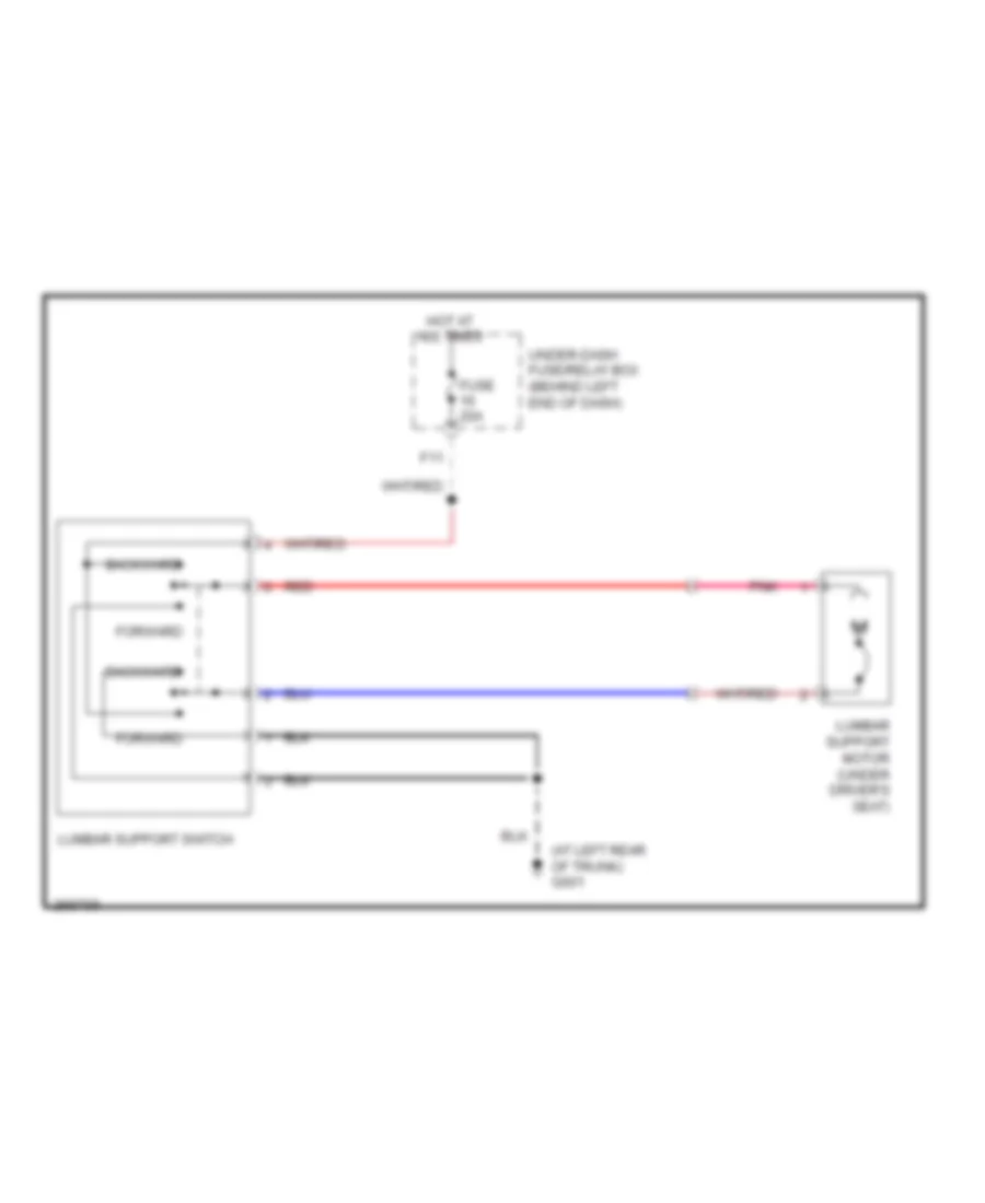 https://portal-diagnostov.com/license.html
Automotive Electricians Portal FZCO
Automotive Electricians Portal FZCO
https://portal-diagnostov.com/license.html
https://portal-diagnostov.com/license.html
Automotive Electricians Portal FZCO
Automotive Electricians Portal FZCOList of elements for Driver"s Lumbar Wiring Diagram for Acura TL Type S 2007:
- (at left rear of trunk) g601
- Backward
- F11
- Forward
- Fuse 20a
- Hot at all times
- Lumbar support motor (under driver's seat)
- Lumbar support switch
- Pnk
- Red
- Under-dash fuse/relay box (behind left end of dash)
Heated Seats Wiring Diagram for Acura TL Type S 2007
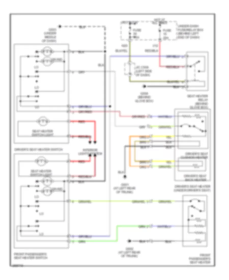 https://portal-diagnostov.com/license.html
Automotive Electricians Portal FZCO
Automotive Electricians Portal FZCO
https://portal-diagnostov.com/license.html
https://portal-diagnostov.com/license.html
Automotive Electricians Portal FZCO
Automotive Electricians Portal FZCOList of elements for Heated Seats Wiring Diagram for Acura TL Type S 2007:
- Driver's seat back heater
- Driver's seat cushion heater
- Driver's seat heater (under driver's seat)
- Driver's seat heater switch
- Front passenger's seat heater
- Front passenger's seat heater switch
- Fuse 20a
- Fuse 7.5a
- G503 (under middle of dash)
- G506 (behind glove box)
- G601 (at left rear of trunk)
- G602 (at left rear of trunk)
- Hot at all times
- Hot in on
- Interior lights system
- J/c c506 (left side of dash)
- N20
- On ind
- Red
- Seat heater relay (behind glove box)
- Seat heater switch light
- Under-dash fuse/relay box (behind left end of dash)
- X12
Passenger Power Seat Wiring Diagram for Acura TL Type S 2007
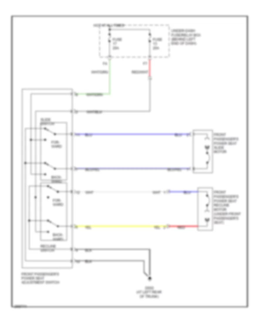 https://portal-diagnostov.com/license.html
Automotive Electricians Portal FZCO
Automotive Electricians Portal FZCO
https://portal-diagnostov.com/license.html
https://portal-diagnostov.com/license.html
Automotive Electricians Portal FZCO
Automotive Electricians Portal FZCOList of elements for Passenger Power Seat Wiring Diagram for Acura TL Type S 2007:
- Back- ward
- For- ward
- Front passenger's power seat adjustment switch
- Front passenger's power seat recline motor (under front passenger's seat)
- Front passenger's power seat slide motor
- Fuse 20a
- G602 (at left rear of trunk)
- Hot at all times
- Recline switch
- Red
- Slide switch
- Under-dash fuse/relay box (behind left end of dash)
POWER TOP/SUNROOF
Power Top/Sunroof Wiring Diagram for Acura TL Type S 2007
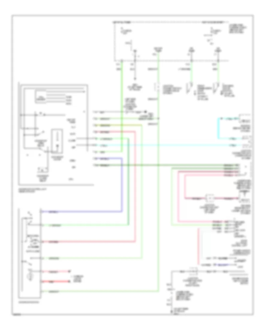 https://portal-diagnostov.com/license.html
Automotive Electricians Portal FZCO
Automotive Electricians Portal FZCO
https://portal-diagnostov.com/license.html
https://portal-diagnostov.com/license.html
Automotive Electricians Portal FZCO
Automotive Electricians Portal FZCOList of elements for Power Top/Sunroof Wiring Diagram for Acura TL Type S 2007:
- (at left rear of trunk) g601
- (at right "b" pillar)
- (left side of dash) junction connector c508
- A16
- A18
- A19
- Antenna
- Auto
- Auto close
- Auto open
- Close
- Cpu
- Door multiplex control unit
- Dr swas
- Dr swdr
- Driver's door key cylinder switch
- Driver's door switch (at left "b" pillar)
- E11
- E15
- Ecm/pcm (behind center of dash)
- Front passenger's door switch
- Fuse 21 7.5a
- Fuse 28 20a
- G501 (under left side of dash)
- G601 (at left rear of trunk)
- H12
- Hall sensor
- Hot at all times
- Hot in on or start
- Ig1
- Interior lights system
- J10
- J11
- Junction connector c507 (left side of dash)
- Junction connector c510 (under middle of dash)
- Junction connector c512 (under middle of dash)
- Junction connector c635 (in left front door)
- Key lock
- Key off timer
- Key unlock
- Keyless entry s/r
- Keyless receiver unit (under left side of dash)
- Lock
- Micu
- Moonroof close relay
- Moonroof control unit (rear of roof)
- Moonroof motor
- Moonroof open relay
- Moonroof switch
- Off
- Open
- P12
- Plsa
- Plsb
- Power window master switch
- Red
- S/r
- Sig out
- Svcc
- Tilt
- Under-dash fuse/relay box (behind left end of dash)
- Unlock
- Vsp
- Vss out
- X14
POWER WINDOWS
Power Windows Wiring Diagram (1 of 2) for Acura TL Type S 2007
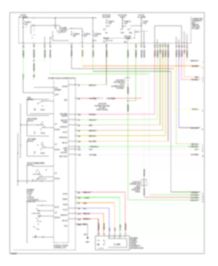 https://portal-diagnostov.com/license.html
Automotive Electricians Portal FZCO
Automotive Electricians Portal FZCO
https://portal-diagnostov.com/license.html
https://portal-diagnostov.com/license.html
Automotive Electricians Portal FZCO
Automotive Electricians Portal FZCOList of elements for Power Windows Wiring Diagram (1 of 2) for Acura TL Type S 2007:
- A16
- A18
- A19
- A20
- A21
- Acc
- Auto
- B-can
- B10
- B11
- B12
- B13
- B14
- Dash)
- Door multiplex control unit
- Down
- Dr dwn
- Dr up
- Driver's power window motor (center of driver's door)
- Driver's switch 0) off 1) up 2) down 3) auto down 4) auto up
- E11
- Front passenger's switch
- Fuse 21 7.5a
- Fuse 24 20a
- Fuse 25 20a
- Fuse 26 30a
- Fuse 27 30a
- Fuse 32 7.5a
- Fuse 7 7.5a
- G501
- H11
- Hot at all times
- Hot in acc or on
- Hot in on or start
- Ig1
- J10
- J13
- J14
- J18
- Junction connector c635 (in left front door)
- Key lock
- Key off timer
- Key unlock
- Keyless entry
- Left rear switch
- Lr down
- Lr up
- Main switch
- Micu
- P/w enable
- P12
- Pg1
- Pls a
- Pls b
- Power window master switch
- Power window relay
- Pulser
- Right rear switch
- Rr down
- Rr up
- Sgnd
- Svcc
- Uart
- Under-dash fuse/relay box (behind left end of dash)
- Vbu
- Vmp1
- X24
- X35
- X37
Power Windows Wiring Diagram (2 of 2) for Acura TL Type S 2007
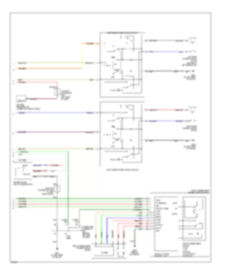 https://portal-diagnostov.com/license.html
Automotive Electricians Portal FZCO
Automotive Electricians Portal FZCO
https://portal-diagnostov.com/license.html
https://portal-diagnostov.com/license.html
Automotive Electricians Portal FZCO
Automotive Electricians Portal FZCOList of elements for Power Windows Wiring Diagram (2 of 2) for Acura TL Type S 2007:
- (not used)
- Auto
- Door multiplex control unit
- Down
- Driver's door key cylinder switch
- Fp dwn
- Fr up
- Front passenger's power window motor
- Front passenger's power window switch
- Front passenger's switch 0) off 1) up 2) down 3) auto down 4) auto up
- G506 (behind glove box)
- G601 (at left rear of trunk)
- G602 (at left rear of trunk)
- Junction connector c507 (left side of dash)
- Junction connector c635 (in left front door)
- Key off timer
- Keyless receiver unit (under left side of dash)
- Left rear power window motor (center of left rear door)
- Left rear power window switch
- Lock
- Off
- P/w enable
- Pg2
- Plsa
- Plsb
- Pulser
- Red
- Right rear power window motor
- Right rear power window switch
- Sgnd
- Sig out
- Svcc
- Uart
- Under-dash fuse/relay box (behind left end of dash)
- Unlock
- Vbu
- Vmp2
- X15
RADIO
Active Noise Control Wiring Diagram for Acura TL Type S 2007
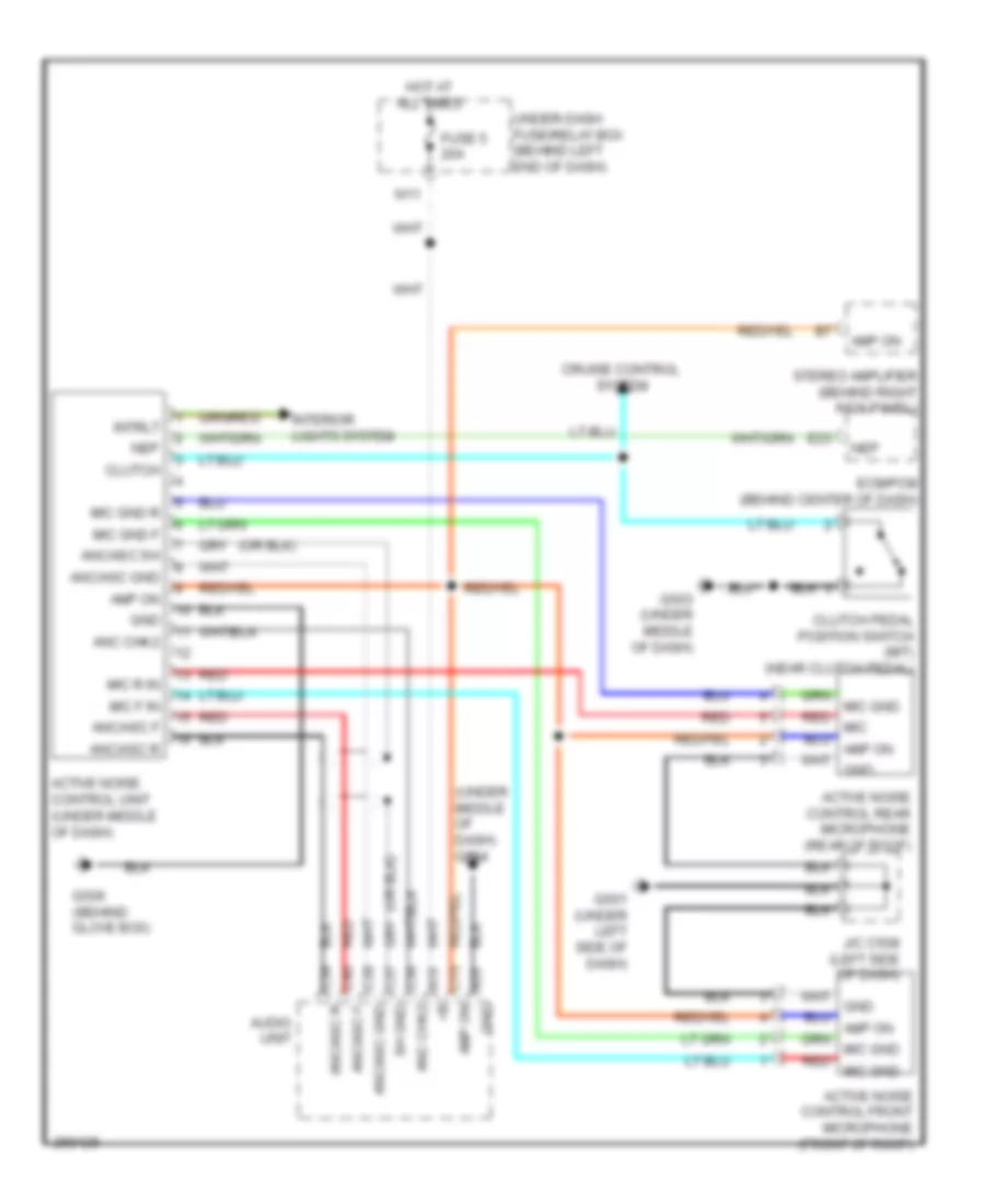 https://portal-diagnostov.com/license.html
Automotive Electricians Portal FZCO
Automotive Electricians Portal FZCO
https://portal-diagnostov.com/license.html
https://portal-diagnostov.com/license.html
Automotive Electricians Portal FZCO
Automotive Electricians Portal FZCOList of elements for Active Noise Control Wiring Diagram for Acura TL Type S 2007:
- (under middle of dash) g504
- A10 +b
- A20 gnd
- Active noise control front microphone (front of roof)
- Active noise control rear microphone (rear of roof)
- Active noise control unit (under middle of dash)
- Amp on
- Anc chk2
- Anc/asc f
- Anc/asc gnd
- Anc/asc r
- Anc/asc sh
- Audio unit
- C15 amp on
- C36 anc chk2
- C37 sh gnd
- C38 anc/asc gnd
- C39 anc/asc r
- C40 anc/asc f
- Clutch
- Clutch pedal position switch (m/t) (near clutch pedal)
- Cruise control system
- E23
- Ecm/pcm (behind center of dash)
- Fuse 5 20a
- G501 (under left side of dash)
- G503 (under middle of dash)
- G506 (behind glove box)
- Gnd
- Hot at all times
- Interior lights system
- Intrlt
- J/c c508 (left side of dash)
- Mic f in
- Mic gnd f
- Mic gnd r
- Mic r in
- N11
- Nep
- Red
- Red mic
- Red mic gnd
- Stereo amplifier (behind right kick panel)
- Under-dash fuse/relay box (behind left end of dash)
Radio Wiring Diagram, with Navigation (1 of 3) for Acura TL Type S 2007
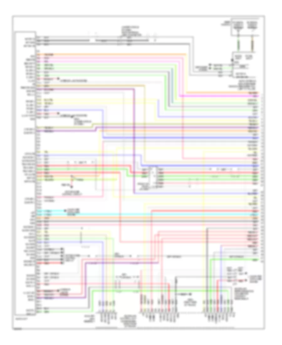 https://portal-diagnostov.com/license.html
Automotive Electricians Portal FZCO
Automotive Electricians Portal FZCO
https://portal-diagnostov.com/license.html
https://portal-diagnostov.com/license.html
Automotive Electricians Portal FZCO
Automotive Electricians Portal FZCOList of elements for Radio Wiring Diagram, with Navigation (1 of 3) for Acura TL Type S 2007:
- (front of roof) j/c c652
- (right side of trunk)
- (under middle of dash) am/fm antenna lead connector
- A1 +b
- A10
- A10 aud r(+)
- A11
- A11 gnd
- A12
- A12 ig1
- A13
- A13 comm 4
- A14
- A14 comm 2
- A15
- A15 comm sh
- A16
- A16 f-can-l
- A17
- A17 bus(-)
- A18
- A18 bus sh
- A19
- A19 l(-)
- A2 acc
- A20
- A20 r(-)
- A3 comm 3
- A4 comm 1
- A6 f-can h
- A7 bus(+)
- A8 aud sh
- A9 aud l(+)
- Acc
- Active noise control circuit
- Acuralink control unit (xm receiver) (right side of trunk)
- Acuralink reprogramming connector (on right rear shelf)
- Am sig input
- Am signal window antenna
- Am/fm antenna amplifier-rear window defogger coil (left "c" pillar)
- Amp mute
- Amp on
- Anc chk2
- Anc/afc f
- Anc/asc r
- Ant gnd
- Ant rf in
- Ant sw +b
- Aud bus sh
- Aud bus(+)
- Aud bus(-)
- Aud l(+)
- Aud l(-)
- Aud r(+)
- Aud r(-)
- Audio unit
- Aux det
- Aux gnd
- Aux l
- Aux r
- Aux sgnd
- Aux sh gnd
- Auxiliary jack assembly
- B10
- B11
- B12
- B13
- B14
- Bus sh
- Bus(+)
- Bus(-)
- C10
- C11
- C12
- C13
- C14
- C15
- C16
- C17
- C18
- C19
- C20
- C21
- C22
- C23
- C24
- C25
- C26
- C27
- C28
- C29
- C30
- C31
- C32
- C33
- C34
- C35
- C36
- C37
- C38
- C39
- C40
- Computer data lines system
- Ctr sp(+)
- Ctr sp(-)
- Defogger system
- Fl sp(+)
- Fl sp(-)
- Fm sig input
- Fm signal window antenna
- Fr sp(+)
- Fr sp(-)
- G504 (under middle of dash)
- G604
- Gnd
- Gnd rg
- Hfl mute
- Hip mute
- Illumi
- Illumi (xm)
- Illumi cont
- Ims0
- Ims1
- Interior lights system
- Let
- Nca
- Pnk
- Rear window
- Red
- Remote
- Remote gnd
- Rg l(+)
- Rl sp(+)
- Rl sp(-)
- Rr sp(+)
- Rr sp(-)
- Security
- Sh gnd
- Sub wf(+)
- Sub wf(-)
- Telm sig sh
- Telm sig(+)
- Telm sig(-)
- Type s
- Vsp
Radio Wiring Diagram, with Navigation (2 of 3) for Acura TL Type S 2007
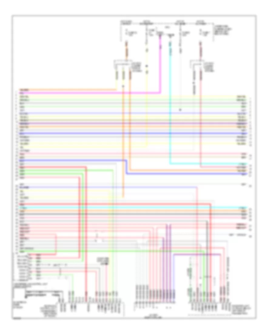 https://portal-diagnostov.com/license.html
Automotive Electricians Portal FZCO
Automotive Electricians Portal FZCO
https://portal-diagnostov.com/license.html
https://portal-diagnostov.com/license.html
Automotive Electricians Portal FZCO
Automotive Electricians Portal FZCOList of elements for Radio Wiring Diagram, with Navigation (2 of 3) for Acura TL Type S 2007:
- A10 bus(+)
- A20 bus(-)
- A9 bus sh
- Acuralink control unit (xm receiver) (right side of trunk)
- B-can
- B1 sat/ter
- B11 sh rg
- B12 gnd rg
- B5 rg l(+)
- C1 audio sh
- C10 audio(-)
- C11
- C12
- C13
- C14 comm 4
- C15 comm 2
- C16
- C2 audio(+)
- C3 hp mute
- C4 b-can
- C5 comm sh
- C6 comm 3
- C7 comm 1
- Comm 1
- Comm 2
- Comm 3
- Comm 4
- Comm sh
- Computer data lines system
- F1 comm 3
- F2 comm 4
- F3 comm 1
- F4 comm 2
- F5 comm sh
- Fuse 32 7.5a
- Fuse 5 20a
- Fuse 7 7.5a
- Fuse 7.5a
- Handsfree link control unit (front of roof)
- Hfl mute
- Hot at all times
- Hot in acc or run
- Hot in on or start
- J/c c510 (under middle of dash)
- J/c c603 (right c-pillar)
- Micu
- N11
- N22
- N36
- Navigation unit (in trunk, below left side of package tray)
- Nca
- Pnk
- Radio sw q1
- Red
- Sat/ter
- Telm sig+
- Telm sig-
- Under-dash fuse/relay box (behind left end of dash)
- X35
- Xm antenna (rear of roof)
Radio Wiring Diagram, with Navigation (3 of 3) for Acura TL Type S 2007
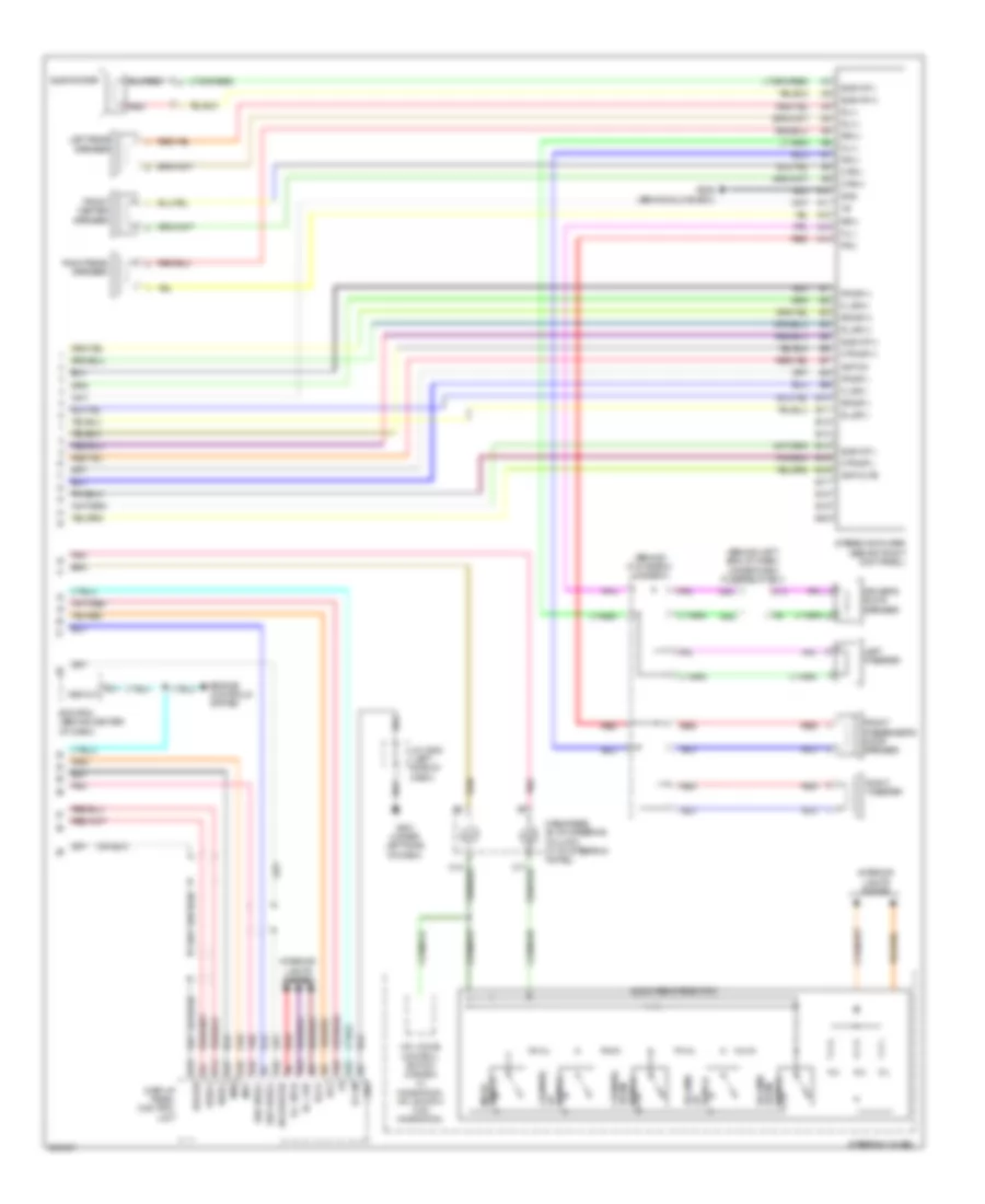 https://portal-diagnostov.com/license.html
Automotive Electricians Portal FZCO
Automotive Electricians Portal FZCO
https://portal-diagnostov.com/license.html
https://portal-diagnostov.com/license.html
Automotive Electricians Portal FZCO
Automotive Electricians Portal FZCOList of elements for Radio Wiring Diagram, with Navigation (3 of 3) for Acura TL Type S 2007:
- (behind glove box) j/c c513
- (behind left end of dash) under-dash fuse/relay box
- A10
- A11
- A12
- A13
- A14
- A15
- A16
- A17
- A18
- A19
- A22
- Acc
- Amp mute
- Amp on
- Aud bus sh
- Aud bus(+)
- Aud bus(-)
- Audio remote switch
- B-can
- B10
- B11
- B12
- B13
- B14
- B15
- B16
- B17
- B18
- B19
- B20
- Bus sh
- Bus(+)
- Bus(-)
- C17
- C18
- Cable reel (b: on steering column) (c: on steering whhel)
- Channel down switch
- Channel up
- Ctr sp(+)
- Ctr sp(-)
- Ctr(+)
- Ctr(-)
- Display panel control unit
- Driver's door speaker
- E11 vss out
- E14
- E15
- Ecm/pcm (behind center of dash)
- Engine controls system
- Fl sp(+)
- Fl sp(-)
- Fl(+)
- Fl(-)
- Fr sp(+)
- Fr sp(-)
- Fr(+)
- Fr(-)
- Front center speaker
- Front passenger's door speaker
- G501 (under left side of dash)
- G506 (behind glove box)
- Gnd
- Hfl-voice control switch (canada w/ navigation) hfl-switch (w/o navigation)
- Ill(+)
- Ill- bulb
- Ill- led
- Ims0
- Ims1
- Interior lights system
- J/c c508 (left side of dash)
- K10
- Left rear speaker
- Left tweeter
- Mode switch
- N23
- N24
- Pnk
- Red
- Right rear speaker
- Right tweeter
- Rl sp(+)
- Rl sp(-)
- Rl(+)
- Rl(-)
- Rr sp(+)
- Rr sp(-)
- Rr(+)
- Rr(-)
- Steering wheel
- Stereo amplifier (behind right kick panel)
- Sub wf(+)
- Sub wf(-)
- Subwoofer
- Switch
- Switch down
- Volume
- Volume up
Radio Wiring Diagram, without Navigation (1 of 3) for Acura TL Type S 2007
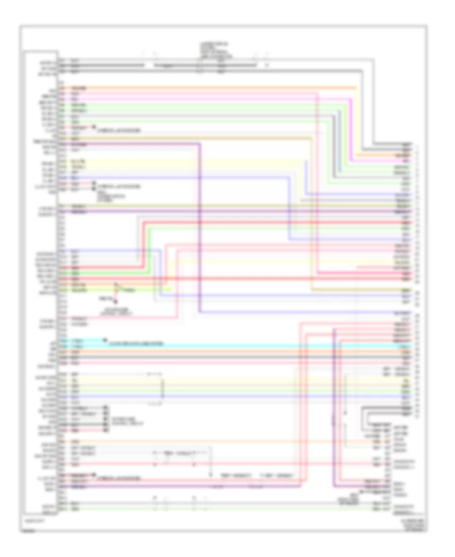 https://portal-diagnostov.com/license.html
Automotive Electricians Portal FZCO
Automotive Electricians Portal FZCO
https://portal-diagnostov.com/license.html
https://portal-diagnostov.com/license.html
Automotive Electricians Portal FZCO
Automotive Electricians Portal FZCOList of elements for Radio Wiring Diagram, without Navigation (1 of 3) for Acura TL Type S 2007:
- (under middle of dash) am/fm antenna lead connector
- A10
- A11
- A12
- A13
- A14
- A15
- A16
- A17
- A18
- A19
- A20
- Acc
- Active noise control circuit
- Amp mute
- Amp on
- Anc chk2
- Anc/afc f
- Anc/asc r
- Ant gnd
- Ant rf in
- Ant sw +b
- Aud bus sh
- Aud bus(+)
- Aud bus(-)
- Aud l(+)
- Aud l(-)
- Aud r(-)
- Aud sh gnd
- Audio unit
- Audr(+)
- Aux det
- Aux gnd
- Aux l
- Aux r
- Aux sgnd
- Aux sh gnd
- B10
- B11
- B12
- B13
- B14
- Bus sh
- Bus(+)
- Bus(-)
- C10
- C11
- C12
- C13
- C14
- C15
- C16
- C17
- C18
- C19
- C20
- C21
- C22
- C23
- C24
- C25
- C26
- C27
- C28
- C29
- C30
- C31
- C32
- C33
- C34
- C35
- C36
- C37
- C38
- C39
- C40
- Computer data lines system
- Ctr sp(+)
- Ctr sp(-)
- Fl sp(+)
- Fl sp(-)
- Fr sp(+)
- Fr sp(-)
- G504 (under middle of dash)
- G604 (right side of trunk)
- Ga +b
- Ga audio l+
- Ga audio l-
- Ga audio r+
- Ga audio r-
- Ga gnd
- Gnd
- Gnd rg
- Hfl mute
- Illumi
- Illumi (xm)
- Illumi cont
- Ims0
- Ims1
- Interior lights system
- Let
- Nca
- Pnk
- Red
- Remote
- Remote gnd
- Rg l(+)
- Rl sp(+)
- Rl sp(-)
- Rr sp(+)
- Rr sp(-)
- Sat/ter
- Security
- Sh gnd
- Sub wf(+)
- Sub wf(-)
- Sys acc
- Sys on
- Telm sig sh
- Telm sig(+)
- Telm sig(-)
- Type s
- Vsp
- Xm receiver (right side of trunk)
Radio Wiring Diagram, without Navigation (2 of 3) for Acura TL Type S 2007
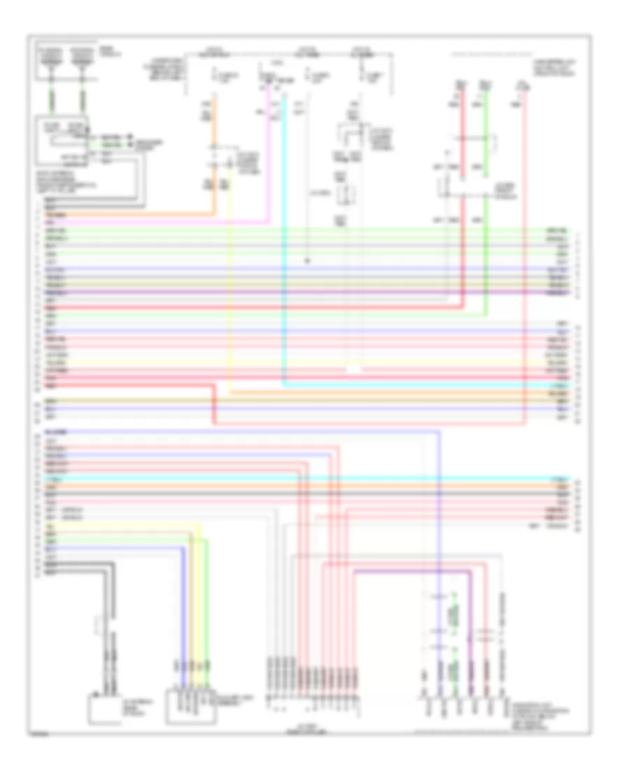 https://portal-diagnostov.com/license.html
Automotive Electricians Portal FZCO
Automotive Electricians Portal FZCO
https://portal-diagnostov.com/license.html
https://portal-diagnostov.com/license.html
Automotive Electricians Portal FZCO
Automotive Electricians Portal FZCOList of elements for Radio Wiring Diagram, without Navigation (2 of 3) for Acura TL Type S 2007:
- A10 bus(+)
- A20 bus(-)
- A9 bus sh
- Am sig input
- Am signal window antenna
- Am/fm antenna amplifier-rear window defogger coil (left "c" pillar)
- Ant rf in
- Ant sw +b
- Aux det
- Aux gnd
- Aux l
- Aux r
- Aux sgnd
- Auxiliary jack assembly
- B-can
- B11 sh rg
- B12 gnd rg
- B5 rg l(+)
- Defogger system
- Fm sig input
- Fm signal window antenna
- Fuse 32 7.5a
- Fuse 5 20a
- Fuse 7 7.5a
- Gnd
- Handsfree link control unit (front of roof)
- Hfl mute
- Hot at all times
- Hot in acc or run
- J/c c510 (under middle of dash)
- J/c c602
- J/c c603 (right c-pillar)
- J/c c652 (front of roof)
- Micu
- N11
- N36
- Navigation unit (canada w/ navigation) (in trunk, below left side of package tray)
- Nca
- Pnk
- Radio sw
- Rear window
- Red
- Telm sig+
- Telm sig-
- Under-dash fuse/relay box (behind left end of dash)
- X35
- Xm antenna (rear of roof)
Radio Wiring Diagram, without Navigation (3 of 3) for Acura TL Type S 2007
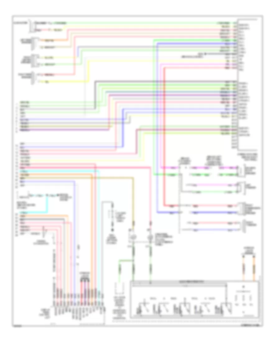 https://portal-diagnostov.com/license.html
Automotive Electricians Portal FZCO
Automotive Electricians Portal FZCO
https://portal-diagnostov.com/license.html
https://portal-diagnostov.com/license.html
Automotive Electricians Portal FZCO
Automotive Electricians Portal FZCOList of elements for Radio Wiring Diagram, without Navigation (3 of 3) for Acura TL Type S 2007:
- (behind glove box) j/c c513
- (behind left end of dash) under-dash fuse/relay box
- A10
- A11
- A12
- A13
- A14
- A15
- A16
- A17
- A18
- A19
- A22
- Acc
- Amp mute
- Amp on
- Aud bus sh
- Aud bus(+)
- Aud bus(-)
- Audio remote switch
- B-can
- B10
- B11
- B12
- B13
- B14
- B15
- B16
- B17
- B18
- B19
- B20
- Bus sh
- Bus(+)
- Bus(-)
- C17
- C18
- Cable reel (b: on steering column) (c: on steering wheel)
- Canada w/ navigation
- Channel down switch
- Channel up
- Ctr sp(+)
- Ctr sp(-)
- Ctr(+)
- Ctr(-)
- Display panel control unit
- Driver's door speaker
- E11 vss out
- E14
- E15
- Ecm/pcm (behind center of dash)
- Engine controls system
- Fl sp(+)
- Fl sp(-)
- Fl(+)
- Fl(-)
- Fr sp(+)
- Fr sp(-)
- Fr(+)
- Fr(-)
- Front center speaker
- Front passenger's door speaker
- G501 (under left side of dash)
- G506 (behind glove box)
- Gnd
- Hfl-voice control switch (canada w/ navigation) hfl-switch (w/o navigation)
- Ill(+)
- Ill- bulb
- Ill- led
- Ims0
- Ims1
- Interior lights system
- J/c c508 (left side of dash)
- K10
- Left rear speaker
- Left tweeter
- Mode switch
- N23
- N24
- Pnk
- Red
- Right rear speaker
- Right tweeter
- Rl sp(+)
- Rl sp(-)
- Rl(+)
- Rl(-)
- Rr sp(+)
- Rr sp(-)
- Rr(+)
- Rr(-)
- Steering wheel
- Stereo amplifier (behind right kick panel)
- Sub wf(+)
- Sub wf(-)
- Subwoofer
- Switch
- Switch down
- Volume
- Volume up
SHIFT INTERLOCK
Reverse Lockout Wiring Diagram, M/T for Acura TL Type S 2007
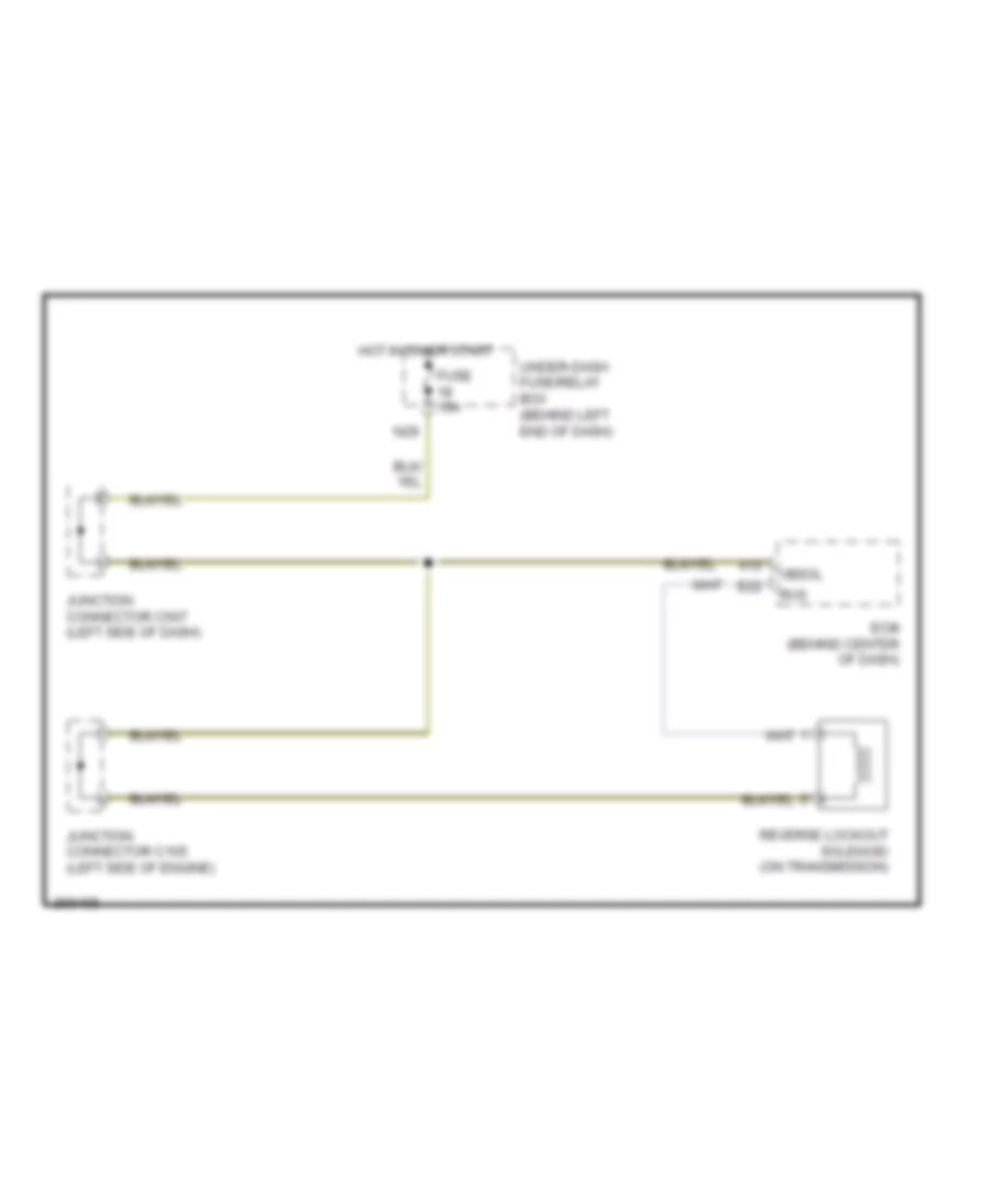 https://portal-diagnostov.com/license.html
Automotive Electricians Portal FZCO
Automotive Electricians Portal FZCO
https://portal-diagnostov.com/license.html
https://portal-diagnostov.com/license.html
Automotive Electricians Portal FZCO
Automotive Electricians Portal FZCOList of elements for Reverse Lockout Wiring Diagram, M/T for Acura TL Type S 2007:
- A10
- E22
- Ecm (behind center of dash)
- Fuse 15a
- Hot in on or start
- Junction connector c105 (left side of engine)
- Junction connector c507 (left side of dash)
- N29
- Reverse lockout solenoid (on transmission)
- Rvs
- Under-dash fuse/relay box (behind left end of dash)
- Vbsol
Shift Interlock Wiring Diagram, A/T for Acura TL Type S 2007
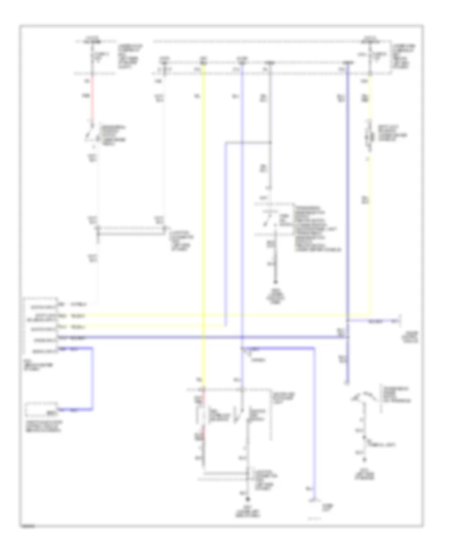 https://portal-diagnostov.com/license.html
Automotive Electricians Portal FZCO
Automotive Electricians Portal FZCO
https://portal-diagnostov.com/license.html
https://portal-diagnostov.com/license.html
Automotive Electricians Portal FZCO
Automotive Electricians Portal FZCOList of elements for Shift Interlock Wiring Diagram, A/T for Acura TL Type S 2007:
- A11
- A26
- Atp-p
- Brake pedal position switch (near brake pedal)
- Canada
- D13
- D14
- Drive input
- Fuse 13 20a
- Fuse 32 7.5a
- G101 (left side of engine)
- G501 (under left side of dash)
- G503 (under middle of dash)
- Gauge control module
- Hot at all times
- Hot in acc or on
- Ig key sw
- Ignition key switch
- Ignition key switch/key light
- Imoes unit
- Junction connector c507 (left side of dash)
- Junction connector c508 (left side of dash)
- Key interlock solenoid
- Key sol
- Micu
- N26
- N39
- P-pin
- P13
- P15
- P16
- Park pin switch
- Pcm (behind center of dash)
- Red
- S2 (thermal joint)
- Sedf
- Shift lock e22
- Shift lock solenoid (under center console)
- Signal input
- Solenoid input
- Stop sw
- Switch input
- Throttle actuator control module (behind glove box)
- Transmission gear selection switch/ park pin switch a/t gear position indicator panel light (transmission gear selection switch & park pin switch: under center console)
- Transmission range switch (on transaxle)
- Under-dash fuse/relay box (behind left end of dash)
- Under-hood fuse/relay box (left rear of engine compt)
STARTING/CHARGING
Charging Wiring Diagram for Acura TL Type S 2007
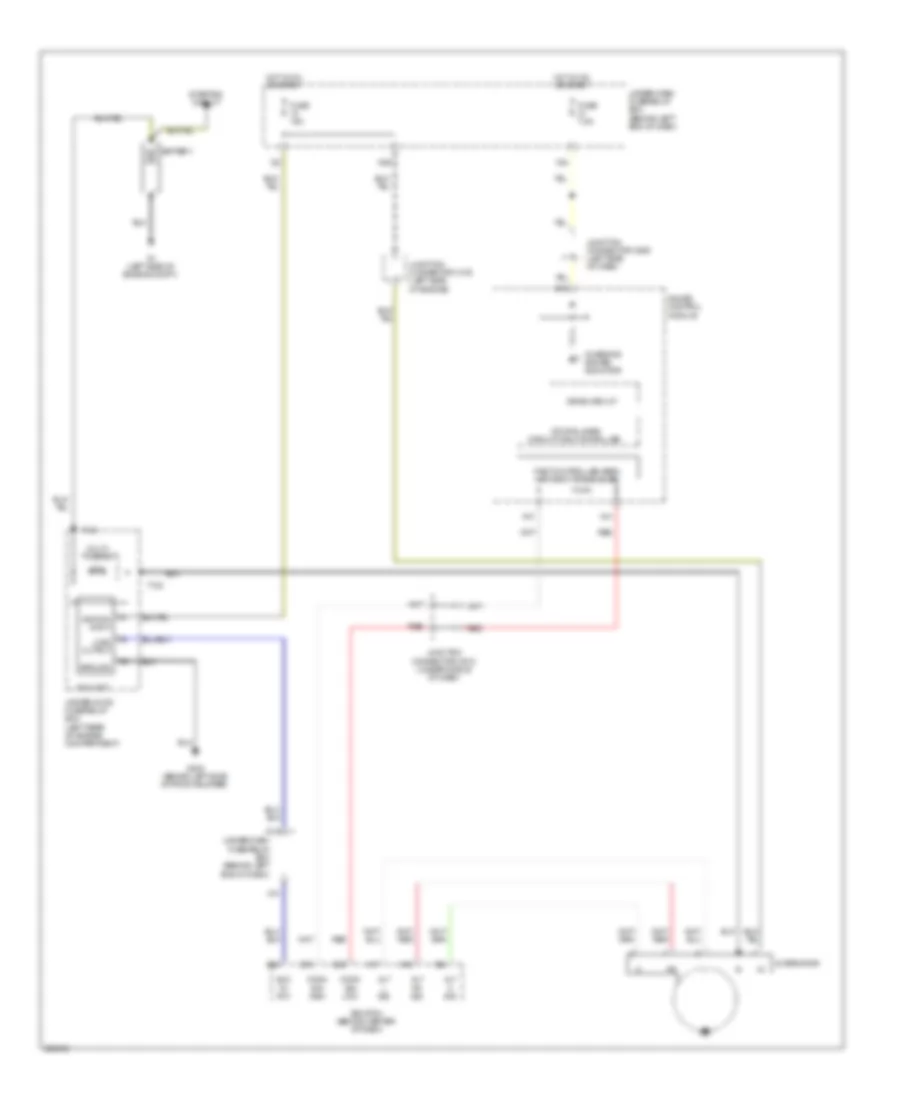 https://portal-diagnostov.com/license.html
Automotive Electricians Portal FZCO
Automotive Electricians Portal FZCO
https://portal-diagnostov.com/license.html
https://portal-diagnostov.com/license.html
Automotive Electricians Portal FZCO
Automotive Electricians Portal FZCOList of elements for Charging Wiring Diagram for Acura TL Type S 2007:
- 120a
- A11
- A12
- A13
- A14
- A24
- Alt c sig
- Alt fr sig
- Alt l sig
- Alternator
- B18
- Battery
- Charging system indicator
- Comm sig high
- Comm sig low
- Cpu/fail safe circuit/can controller
- D13
- Drive circuit
- E15
- E18
- E26
- Ecm/pcm (behind center of dash)
- Eld in- put
- Eld unit
- Fast controller area network transceiver
- Fuse 15a
- Fuse 7.5a
- G1 (left side of engine compt)
- G302 (behind left side of front bumper)
- Gauge control module
- Ground
- Hot in on or start
- Ignition input
- Junction connector c105 (left side of engine)
- Junction connector c506 (left side of dash)
- Junction connector c512 (under middle of dash)
- Load output
- Multi- fuse 22
- N29
- Red
- Starting circuit
- T101
- T102
- Under-dash fuse/relay box (behind left end of dash)
- Under-hood fuse/relay box (left rear of engine compartment)
- X10
- X34
Starting Wiring Diagram, A/T for Acura TL Type S 2007
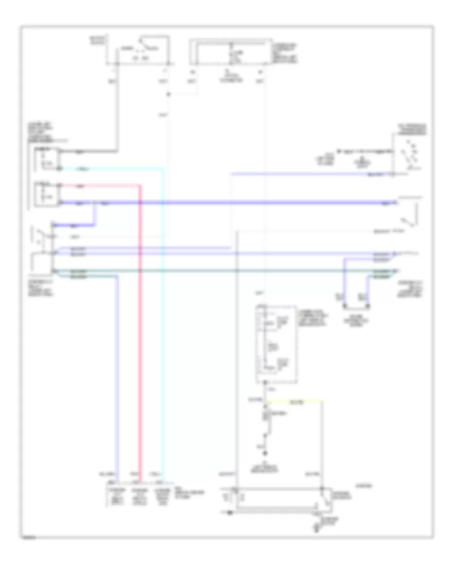 https://portal-diagnostov.com/license.html
Automotive Electricians Portal FZCO
Automotive Electricians Portal FZCO
https://portal-diagnostov.com/license.html
https://portal-diagnostov.com/license.html
Automotive Electricians Portal FZCO
Automotive Electricians Portal FZCOList of elements for Starting Wiring Diagram, A/T for Acura TL Type S 2007:
- (on transaxle) transmission range switch
- (under left side of dash) auxiliary under-dash fuse holder
- 120a
- 50a
- 7.5a
- Battery
- E21
- Eld unit
- Fuse 35
- Fuse 36
- Fuse 7.5a
- G1 (left side of engine compt)
- G101 (left side of dash)
- Hd in
- Ignition switch
- Lock
- Multi- fuse
- On acc
- Option connector
- Pcm (behind center of dash)
- Pl in
- Pnk
- Power distribution system
- S2 (thermal joint)
- Start
- Starter
- Starter cut relay (strly)
- Starter cut relay 1 (under left side of dash)
- Starter cut relay 2 (strld)
- Starter cut relay 2 (under left side of dash)
- Starter motor
- Starter solenoid
- Starter switch signal (sts)
- T101
- Under-dash fuse/relay box (behind left end of dash)
- Under-hood fuse/relay box (left rear of engine compt)
Starting Wiring Diagram, M/T for Acura TL Type S 2007
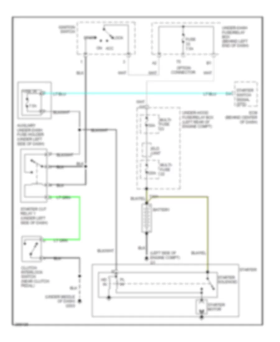 https://portal-diagnostov.com/license.html
Automotive Electricians Portal FZCO
Automotive Electricians Portal FZCO
https://portal-diagnostov.com/license.html
https://portal-diagnostov.com/license.html
Automotive Electricians Portal FZCO
Automotive Electricians Portal FZCOList of elements for Starting Wiring Diagram, M/T for Acura TL Type S 2007:
- (left side of engine compt)
- (under middle of dash) g503
- 120a
- 50a
- 7.5a
- Auxiliary under-dash fuse holder (under left side of dash)
- Battery
- Clutch interlock switch (near clutch pedal)
- Ecm (behind center of dash)
- Eld unit
- Fuse 36
- Fuse 7.5a
- Hd in
- Ignition switch
- Lock
- Multi- fuse
- On acc
- Option connector
- Pl in
- Start
- Starter
- Starter cut relay 1 (under left side of dash)
- Starter motor
- Starter solenoid
- Starter switch signal (sts)
- Under-dash fuse/relay box (behind left end of dash)
- Under-hood fuse/relay box (left rear of engine compt)
SUPPLEMENTAL RESTRAINTS
Supplemental Restraints Wiring Diagram (1 of 2) for Acura TL Type S 2007
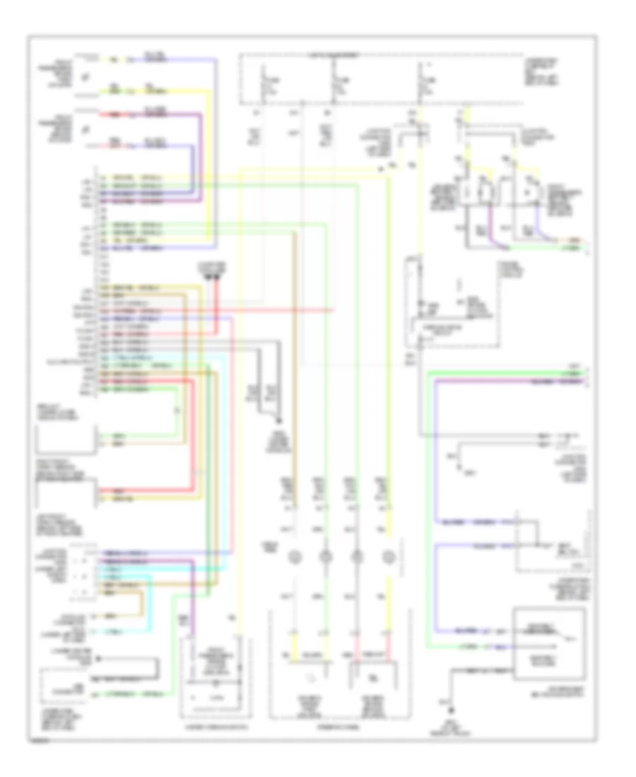 https://portal-diagnostov.com/license.html
Automotive Electricians Portal FZCO
Automotive Electricians Portal FZCO
https://portal-diagnostov.com/license.html
https://portal-diagnostov.com/license.html
Automotive Electricians Portal FZCO
Automotive Electricians Portal FZCOList of elements for Supplemental Restraints Wiring Diagram (1 of 2) for Acura TL Type S 2007:
- (under center console) g505
- A10
- A11
- A12
- A13
- A14
- A15
- A16
- A17
- A18
- A19
- A20
- A21
- A22
- A23
- A24
- A25
- A26
- A27
- A28
- B10
- B18
- Cable reel
- Computer data lines system
- Data link connector (dlc) (under left side of dash)
- Dlc input/output
- Driver's air bag first inflator
- Driver's air bag second inflator
- Driver's seat belt buckle switch
- Driver's seat belt tension reducer solenoid
- F-can+
- F-can-
- F14
- Front passenger's air bag cut-off indicator
- Front passenger's air bag first inflator
- Front passenger's air bag second inflator
- Front passenger's seat belt tension reducer solenoid
- Fuse 10a
- Fuse 7.5a
- G501
- G505 (under center console)
- G601 (at left rear of trunk)
- Gauge control module
- Gnd a
- Gnd b
- H14
- Hazard warning switch
- Hot in on or start
- Ignition
- Junction connector c506 (left side of dash)
- Junction connector c508 (left side of dash)
- Junction connector c509 (under left side of dash)
- Junction connector c602
- La1 +
- La1 -
- La2 +
- La2 -
- Left front impact sensor (behind left side of front bumper)
- Lfs +
- Lfs -
- Mes
- Mes connector
- Micu
- N41
- Ptt
- Ra1 +
- Ra1 -
- Ra2 +
- Ra2 -
- Red
- Rfs +
- Rfs -
- Right front impact sensor (behind right side of front bumper)
- Scs
- Seat belt buckled
- Seat belt sw
- Seat belt unbuckled
- Side air bag cut-off indicator
- Srs ind
- Srs unit (under lower middle of dash)
- Steering wheel
- Under-dash fuse/relay box (behind left end of dash)
- Warning drive circuit
- X34
Supplemental Restraints Wiring Diagram (2 of 2) for Acura TL Type S 2007
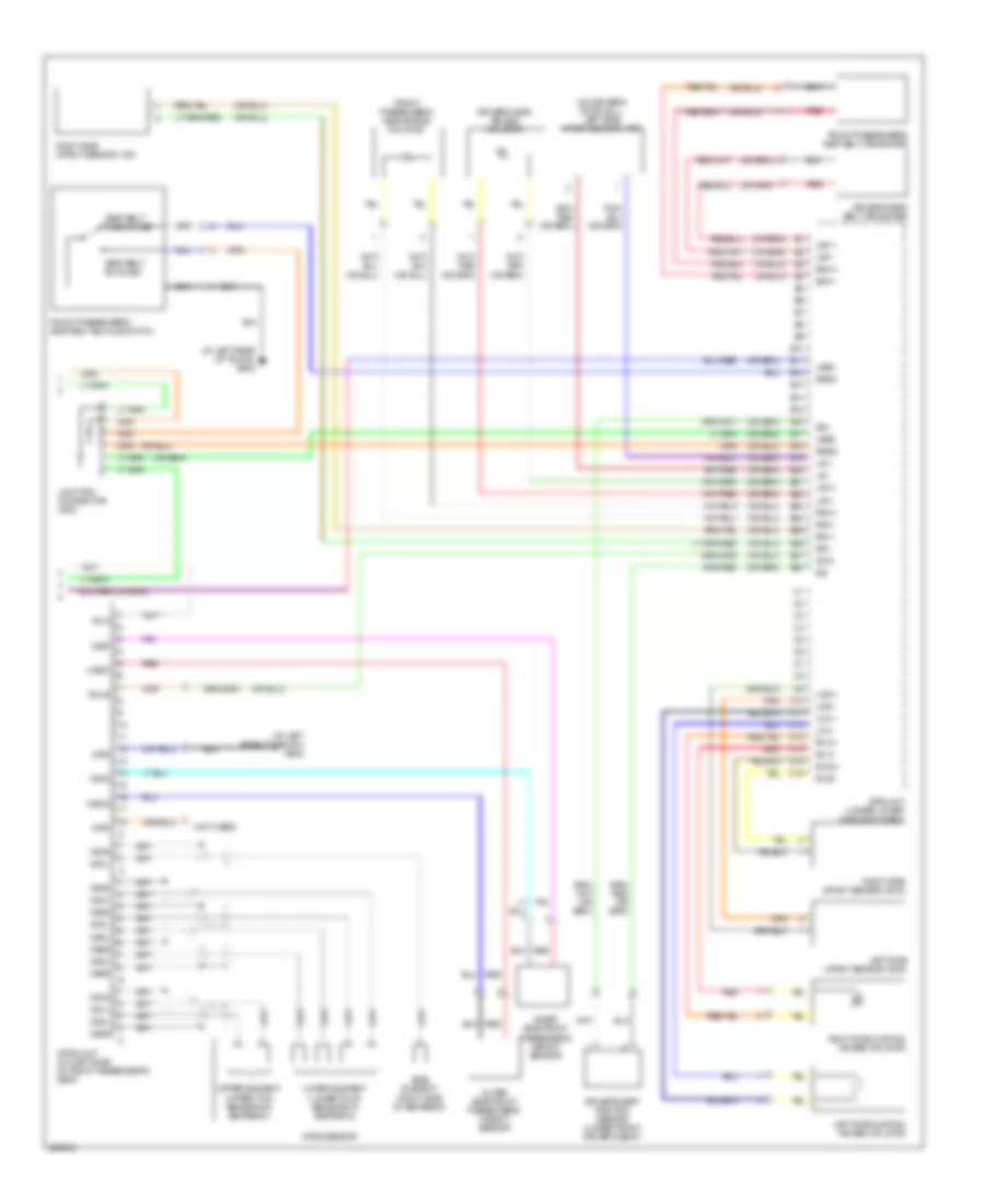 https://portal-diagnostov.com/license.html
Automotive Electricians Portal FZCO
Automotive Electricians Portal FZCO
https://portal-diagnostov.com/license.html
https://portal-diagnostov.com/license.html
Automotive Electricians Portal FZCO
Automotive Electricians Portal FZCOList of elements for Supplemental Restraints Wiring Diagram (2 of 2) for Acura TL Type S 2007:
- (at left rear of trunk) g602
- (not used)
- (on driver's door sill) left side impact sensor (1st)
- B10
- B11
- B12
- B13
- B14
- B15
- B16
- B17
- B18
- B19
- B20
- B21
- B22
- B23
- B24
- B25
- B26
- B27
- B28
- C10
- C11
- C12
- C13
- C14
- C15
- C16
- Driver's seat belt tensioner
- Driver's seat position sensor (under front driver's seat)
- Driver's side air bag inflator
- Front passenger's seat belt buckle switch
- Front passenger's seat belt tensioner
- Front passenger's side air bag inflator
- Grd
- Inner side front passenger's weight sensor
- Junction connector c602
- Lbsc
- Lbsd
- Lca +
- Lca -
- Lcsi +
- Lcsi -
- Left side curtain air bag inflator
- Left side impact sensor (2nd)
- Lower element (lower four sensors in seatback)
- Lrp +
- Lrp -
- Lsa +
- Lsa -
- Lsi +
- Lsi -
- Ods
- Odus
- Opds sensor
- Opds unit (on left side of front passenger's seat)
- Os1l
- Os1s
- Os2l
- Os2s
- Os3l
- Os3s
- Os4l
- Os4s
- Os5l
- Os5s
- Os6l
- Os6s
- Os7l
- Os7s
- Outer side front passenger's weight sensor
- Pow
- Rbsc
- Rbsd
- Rca +
- Rca -
- Rcsi +
- Rcsi -
- Red
- Right side curtain air bag inflator
- Right side impact sensor (1st)
- Right side impact sensor (2nd)
- Rrp +
- Rrp -
- Rsa +
- Rsa -
- Rsi +
- Rsi -
- Seat belt buckled
- Seat belt unbuckled
- Side element (right side of seatback)
- Srs unit (under lower middle of dash)
- Ss+
- Ss-
- Upper element (upper two sensors in seatback)
- Wrn
- Wsig
- Wsip
- Wsog
- Wsop
TRANSMISSION
A/T Wiring Diagram (1 of 2) for Acura TL Type S 2007
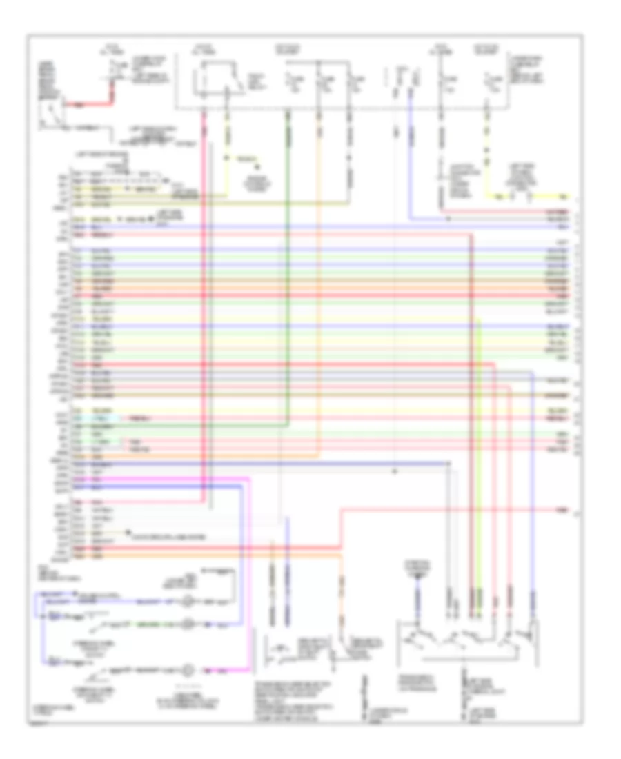 https://portal-diagnostov.com/license.html
Automotive Electricians Portal FZCO
Automotive Electricians Portal FZCO
https://portal-diagnostov.com/license.html
https://portal-diagnostov.com/license.html
Automotive Electricians Portal FZCO
Automotive Electricians Portal FZCOList of elements for A/T Wiring Diagram (1 of 2) for Acura TL Type S 2007:
- (left side of dash) junction connector c506
- (left side of dash) junction connector c507
- (left side of engine) g101
- (left side of engine) s2 (thermal joint)
- (near brake pedal) brake pedal position switch
- (under middle of dash) g503
- A10
- Apsa
- Apsb
- At at all times
- Atft
- Atp-p p16
- Atp-r p20
- Atpd
- Atpfwd
- Atpl
- Atpn
- Atpp
- Atpr
- Atprvs
- B15
- B19
- B23
- Bksw
- C10
- C11
- C12
- C14
- C15
- C16
- C18
- C19
- C20
- C21
- C22
- Cable reel (b: on steering column) (c: on steering wheel)
- Canh
- Canl
- Computer data lines system
- Cruise control system
- D12
- D13
- D15
- D16
- D17
- Down
- E13
- E15
- E16
- E19
- E26
- E30
- Engine controls system
- Fuse 15a
- Fuse 20a
- Fuse 7.5a
- G101 (left side of engine)
- G501 (under left side of dash)
- Hot at all times
- Hot in on or start
- Ig1
- Igp
- Junction connector c510 (under middle of dash)
- Lg1
- Lg2
- Lsa
- Lsb
- Lsc
- Map
- Micu
- Mrly
- N29
- Off
- Op2sw
- Op3sw
- Op4sw
- Pcm (behind center of dash)
- Pg1
- Pg2
- Pgm-fi main relay 1
- Pnk
- Red
- Scs
- Sdn
- Sdnp
- Sequential sportshift a/t shift switch
- Sequential sportshift mode switch
- Sg1
- Sg2
- Sg3
- Sha
- Shb
- Shc
- Shd
- Smode
- Starting/ charging system
- Steering wheel (type s)
- Steering wheel downshift (+) switch
- Steering wheel upshift (+) switch
- Sup
- Supp
- Transmission gear selection switch/park pin switch/a/t gear position indicator panel light (transmission gear selection switch/park pin switch: under center console)
- Transmission range switch (on transaxle)
- Under-dash fuse/relay box (behind left end of dash)
- Under-hood fuse/relay box (left rear of engine compt)
- Vbsol
- Vbsol2
- Vcc1
- Vcc2
- Vcc3
- X20
- X31
- X34
- X35
- X38
A/T Wiring Diagram (2 of 2) for Acura TL Type S 2007
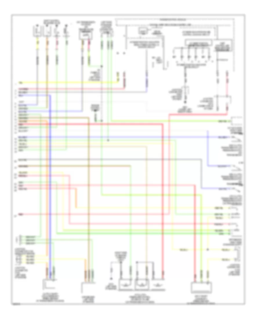 https://portal-diagnostov.com/license.html
Automotive Electricians Portal FZCO
Automotive Electricians Portal FZCO
https://portal-diagnostov.com/license.html
https://portal-diagnostov.com/license.html
Automotive Electricians Portal FZCO
Automotive Electricians Portal FZCOList of elements for A/T Wiring Diagram (2 of 2) for Acura TL Type S 2007:
- (left side of engine) junction connector c105
- (on transmission housing)
- (right side of engine) (thermal joint) s1
- 2nd clutch transmission fluid pressure switch (on transmission)
- 3rd clutch transmission fluid pressure switch (on transmission)
- 4th clutch transmission fluid pressure switch (on transmission)
- A/t clutch pressure control solenoid valves (on transmission housing)
- A/t gear indicator/cruise control dimming circuit
- A/t gear position detection circuit
- A/t gear position indicator
- A/t gear position indicator drive circuit
- A11
- A13
- A14
- App sensor (right side of engine compt)
- Atf temperature sensor
- B10
- B17
- B18
- Brightness control & dimming circuit
- Cpu/fail safe circuit/can controller
- Drive circuit
- Engine control system
- Fast controller area network transceiver
- G101 (left side of engine)
- G501 (under left side of dash)
- Gauge control module
- Imt actuator (right side of engine)
- Input shaft (mainshaft) speed sensor (in transmission housing)
- Junction connector c105 (left side of engine)
- Junction connector c106 (middle of engine)
- Junction connector c508 (left side of dash)
- Junction connector c512 (under middle of dash)
- Lcd back light
- Map sensor (left side of engine)
- Output shaft (countershaft) speed sensor (in transmission housing)
- Pnk
- Red
- S3 (thermal joint) (left side of engine)
- Shift control solenoid valve
- Shift ind
TRUNK, TAILGATE, FUEL DOOR
Trunk, Tailgate, Fuel Door Wiring Diagram for Acura TL Type S 2007
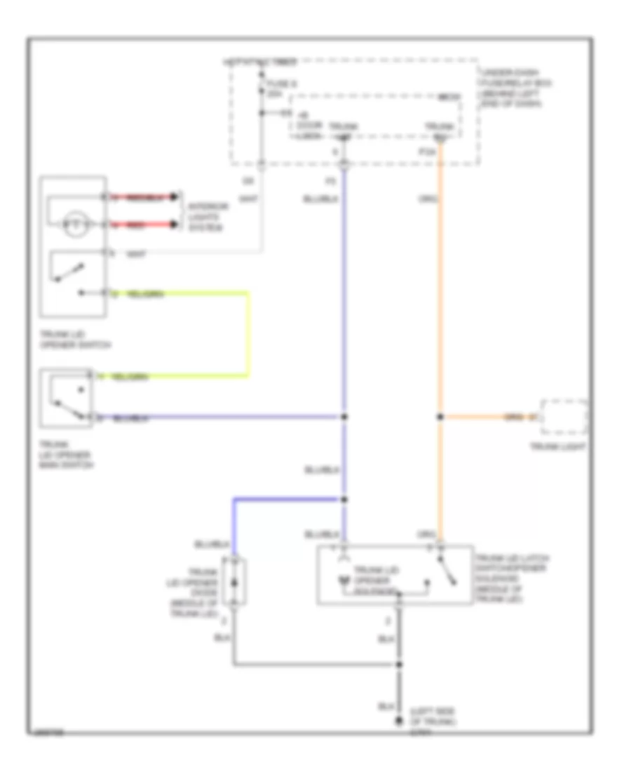 https://portal-diagnostov.com/license.html
Automotive Electricians Portal FZCO
Automotive Electricians Portal FZCO
https://portal-diagnostov.com/license.html
https://portal-diagnostov.com/license.html
Automotive Electricians Portal FZCO
Automotive Electricians Portal FZCOList of elements for Trunk, Tailgate, Fuel Door Wiring Diagram for Acura TL Type S 2007:
- (left side of trunk) g701
- +b door lock
- Fuse 8 20a
- Hot at all times
- Interior lights system
- Micu
- P24
- Red
- Trunk act
- Trunk lid latch switch/opener solenoid (middle of trunk lid)
- Trunk lid opener diode (middle of trunk lid)
- Trunk lid opener main switch
- Trunk lid opener solenoid
- Trunk lid opener switch
- Trunk light
- Trunk sw
- Under-dash fuse/relay box (behind left end of dash)
WARNING SYSTEMS
Chime Wiring Diagram for Acura TL Type S 2007
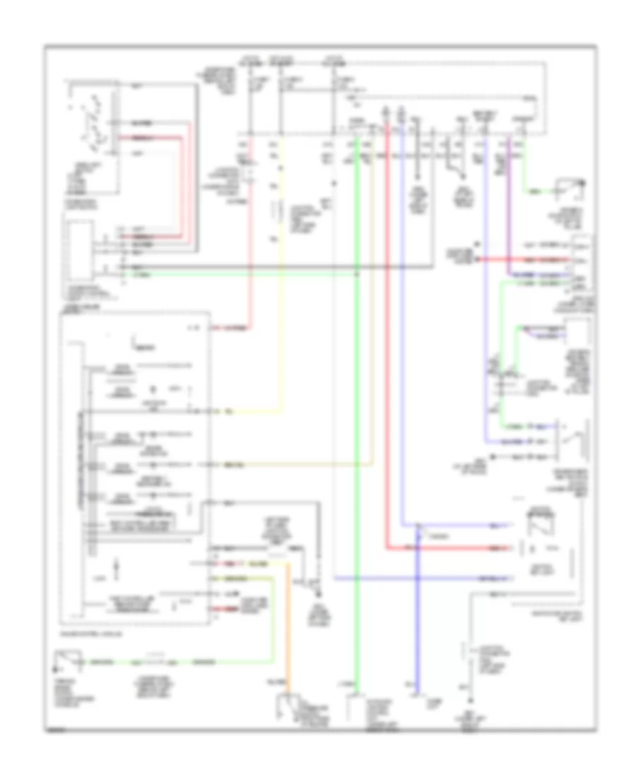 https://portal-diagnostov.com/license.html
Automotive Electricians Portal FZCO
Automotive Electricians Portal FZCO
https://portal-diagnostov.com/license.html
https://portal-diagnostov.com/license.html
Automotive Electricians Portal FZCO
Automotive Electricians Portal FZCOList of elements for Chime Wiring Diagram for Acura TL Type S 2007:
- (left side of dash) junction connector c508
- 0) off 1) park 2) auto 3) head
- 7.5a
- Automatic lighting control unit (under left side of dash)
- B-can
- Beeper
- Body controller area network transceiver
- Brake system ind
- Can-h
- Can-l
- Canada
- Combination light switch
- Combination switch control unit
- Computer data lines system
- Cpu/fail safe circuit/can controller
- Drive circuit
- Driver's door switch (at left "b" pillar)
- Driver's seat belt buckle switch (under driver's seat)
- Driver's seat belt tension reducer solenoid (base of left ``b" pillar)
- Drswdr
- E15
- F14
- Fast controller area network transceiver
- Fuse 21
- Fuse 6
- Fuse 7
- G501 (under left side of dash)
- G502 (under left side of dash)
- G601 (at left rear of trunk)
- Gauge control module
- H14
- Headlight switch
- Hot at all times
- Hot in on or start
- Ig key lt
- Ig key sw
- Ig1
- Ignition key light
- Ignition key switch
- Ignition key switch/ key light
- Imoes unit
- Junction connector c506 (left side of dash)
- Junction connector c508 (left side of dash)
- Junction connector c510 (under middle of dash)
- Junction connector c602
- Lbsc
- Lbso
- Lights on ind
- Low oil pressure ind
- Micu
- N15
- N28
- N30
- N34
- N42
- Oil pressure switch (right side of engine)
- P13
- Parking brake switch (under center console)
- Red
- Seat belt reminder ind
- Seat belt switch
- Sg-1
- Sg-2
- Srs unit (under lower middle of dash)
- Under-dash fuse/relay box (behind left end of dash)
- Wiper/washer switch
- X27
- X34
- X35
Tire Pressure Monitoring Wiring Diagram for Acura TL Type S 2007
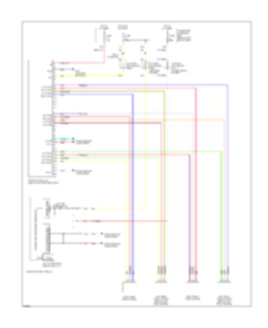 https://portal-diagnostov.com/license.html
Automotive Electricians Portal FZCO
Automotive Electricians Portal FZCO
https://portal-diagnostov.com/license.html
https://portal-diagnostov.com/license.html
Automotive Electricians Portal FZCO
Automotive Electricians Portal FZCOList of elements for Tire Pressure Monitoring Wiring Diagram for Acura TL Type S 2007:
- A13
- A14
- B17
- B18
- Can h
- Can l
- Computer data lines system
- Cpu/fail safe circuit/can controller
- Fast controller area network transceiver
- Fuse 7.5a
- G701 (left side of trunk)
- Gauge control module
- Gnd
- Hot at all times
- Hot in on or start
- Ig1
- Junction connector c506 (left side of dash)
- Junction connector c510 (under middle of dash)
- Junction connector c602
- K-line
- Left front tpms initiator (behind left front fender)
- Left rear tpms initiator (behind left rear fender)
- Lf lf gnd
- Lf lf pwr
- Lf lf sig
- Low tire pressure ind
- Lr lf gnd
- Lr lf pwr
- Lr lf sig
- Multi-information display (mid) unit
- N40
- Pnk
- Red
- Rf lf gnd
- Rf lf pwr
- Rf lf sig
- Right front tpms initiator
- Right rear tpms initiator
- Rr lf gnd
- Rr lf pwr
- Rr lf sig
- Tpms control unit (behind left rear seat back)
- Tpms indicator
- Under-dash fuse/relay box (behind left end of dash)
- Usa w/ navigation
- Warning drive circuit
- X34
- X35
WIPER/WASHER
Wiper/Washer Wiring Diagram for Acura TL Type S 2007
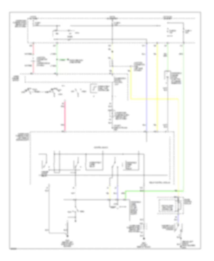 https://portal-diagnostov.com/license.html
Automotive Electricians Portal FZCO
Automotive Electricians Portal FZCO
https://portal-diagnostov.com/license.html
https://portal-diagnostov.com/license.html
Automotive Electricians Portal FZCO
Automotive Electricians Portal FZCOList of elements for Wiper/Washer Wiring Diagram for Acura TL Type S 2007:
- (at left rear of trunk) g601
- B-can
- B18
- Combination switch control unit
- Computer data lines system
- Control block
- Cpu/fail safe circuit/can controller
- D11
- Front bumper) g302
- Fuse 11 30a
- Fuse 20 15a
- Fuse 21 7.5a
- Fuse 7 7.5a
- G302 (behind left side of front bumper)
- G601 (at left rear of trunk)
- Gauge control module
- High
- Hot at all times
- Hot in on or start
- Ig1
- Int
- Int off
- Intermittent dwell time controller
- Intermittent wiper relay
- Junction connector c506 (left side of dash)
- Junction connector c510 (under middle of dash)
- K10
- Low
- Micu
- Mist
- N18
- N42
- Off
- Park
- Pnk
- Relay control module
- Run
- Under-dash fuse/relay box (behind left end of dash)
- Under-hood fuse/relay box (left rear of engine compt)
- Vbu
- Wash
- Washer fluid level switch (canada)
- Washer motor relay
- Windshield washer motor (in bottom of washer reservoir)
- Windshield wiper high relay
- Windshield wiper motor (in left rear of engine compt)
- Wiper/ washer switch
- X27
- X34
- X35

 Čeština
 Dansk
Dansk Deutsch
 Ελληνικά
 English
 English
 Español
 Suomi
Suomi Français
 Français
 עברית
עברית Hrvatski
 Magyar
 Italiano
 日本語
日本語 한국어
한국어 Nederlands
 Polski
 Português
 Português
 Română
 Русский
 Slovenčina
 Slovenščina
 Svenska
 中文 (中国)
