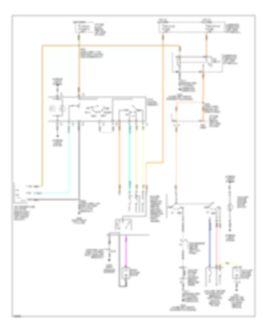
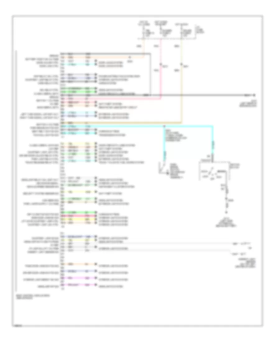
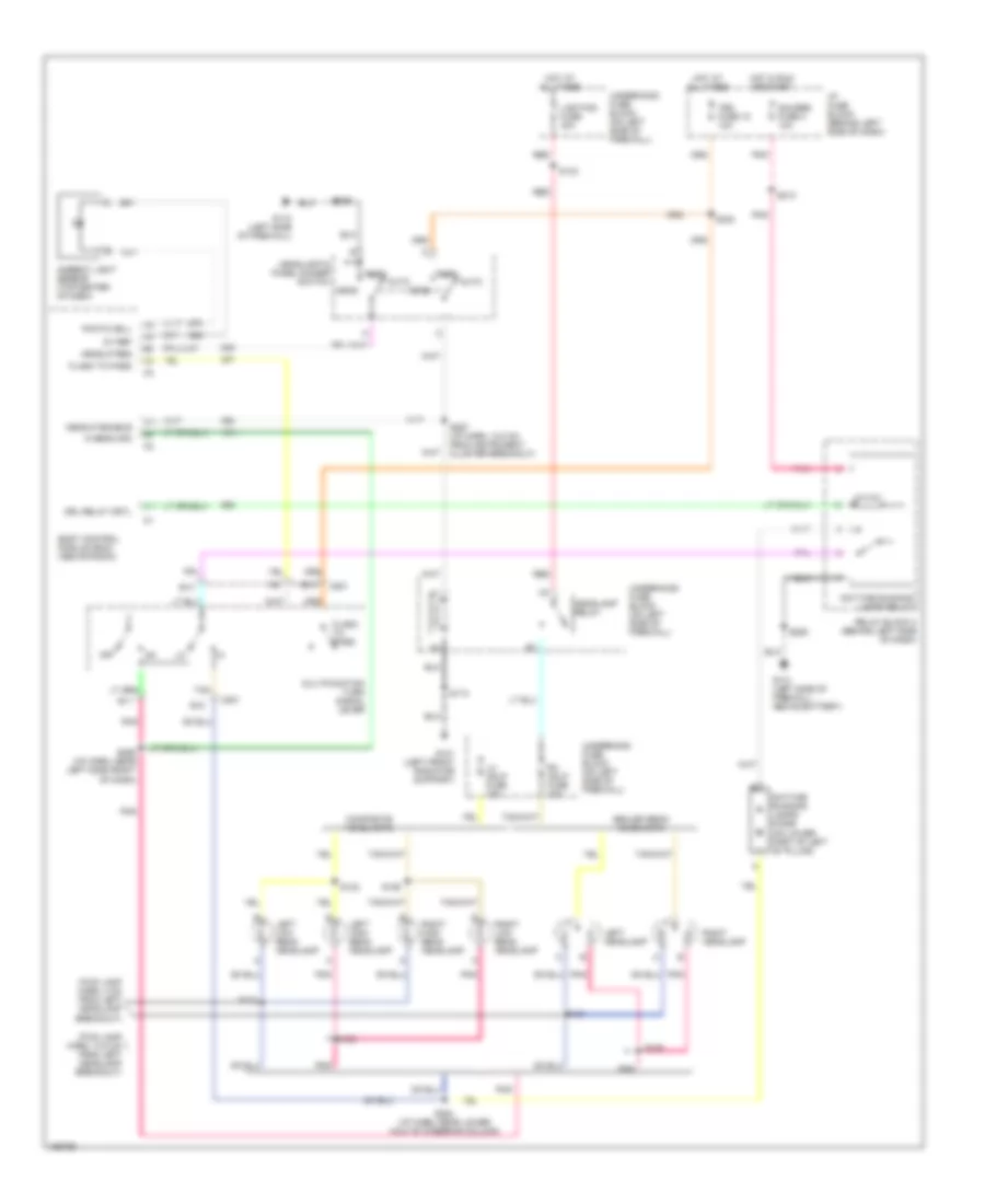
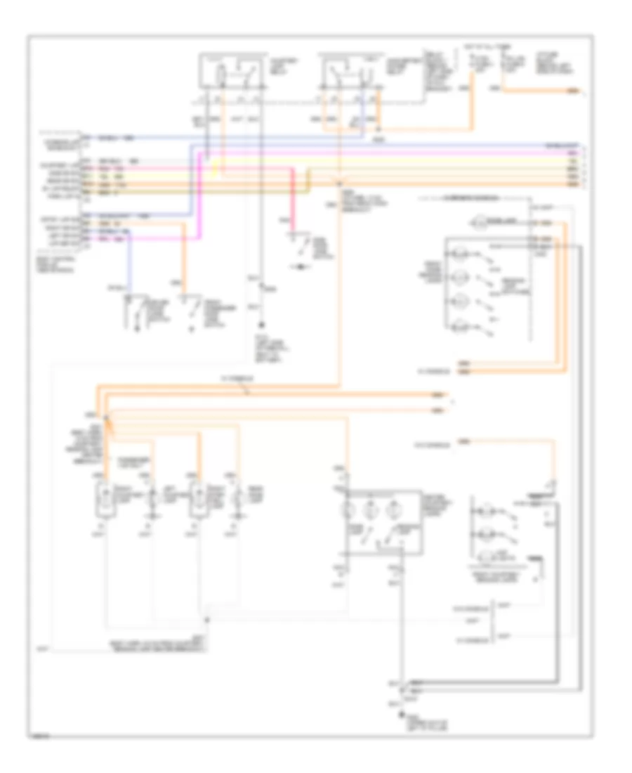
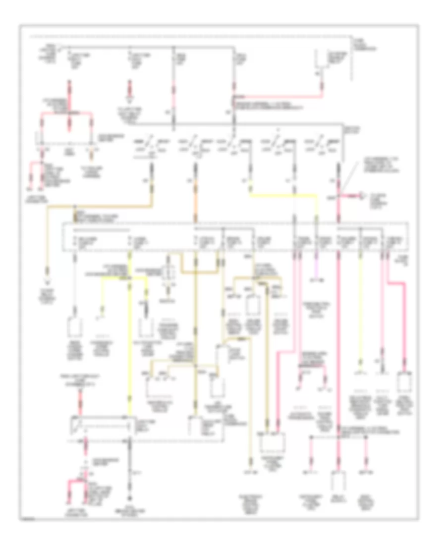
AIR CONDITIONING
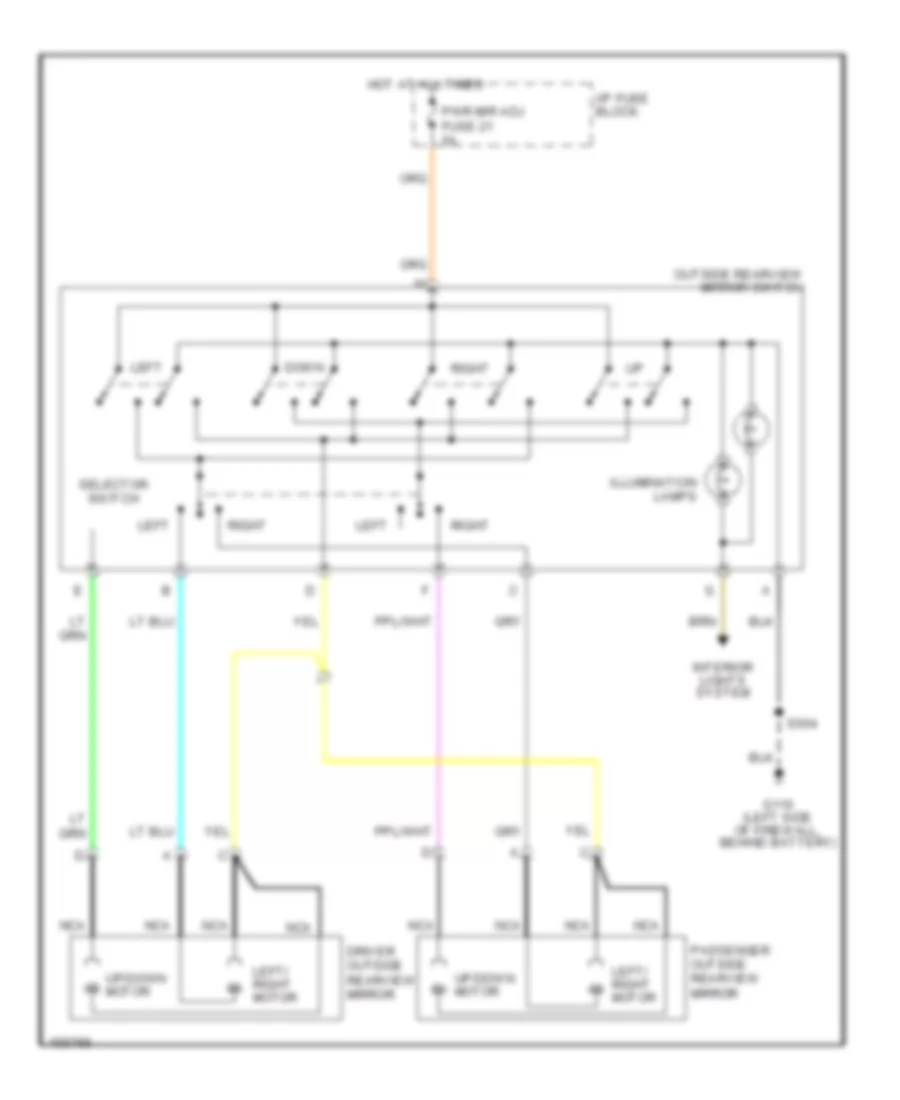
Compressor Wiring Diagram for Chevrolet Astro 2002
 https://portal-diagnostov.com/license.html
Automotive Electricians Portal FZCO
Automotive Electricians Portal FZCO
https://portal-diagnostov.com/license.html
https://portal-diagnostov.com/license.html
Automotive Electricians Portal FZCO
Automotive Electricians Portal FZCO
List of elements for Compressor Wiring Diagram for Chevrolet Astro 2002:
- 11 cm from oil pressure switch breakout)
- A/c comp fuse 10a
- A/c comp relay
- A/c compressor clutch
- A/c compressor clutch diode (in underhood fuse block)
- A/c enable relay
- A/c high pressure switch (rear of a/c comp)
- A/c low press
- A/c low pressure switch (on a/c accumulator)
- A/c request
- Bi-lv
- Blend
- Def
- G104 (lower left side of evaporative housing)
- Heat
- Hot at all times
- Hot in run
- Hot in run or start
- Htr-a/c fuse 12 20a
- Hvac control assembly
- I/p fuse block (behind left side of dash)
- Ign-e fuse 10a
- Max
- Norm
- Off
- Pnk
- Powertrain control module (below underhood fuseblock, on left side of firewall)
- S111 (engine harn, 17 cm from underhood fuse block)
- S224 (dash harn. 17 cm from body control module breakout)
- Underhood fuse block (left side of firewall)
- Vent
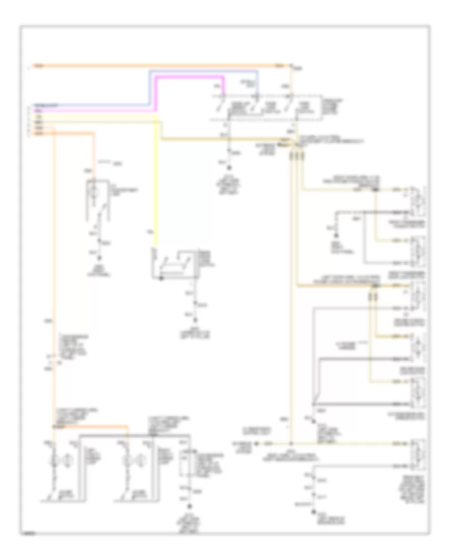
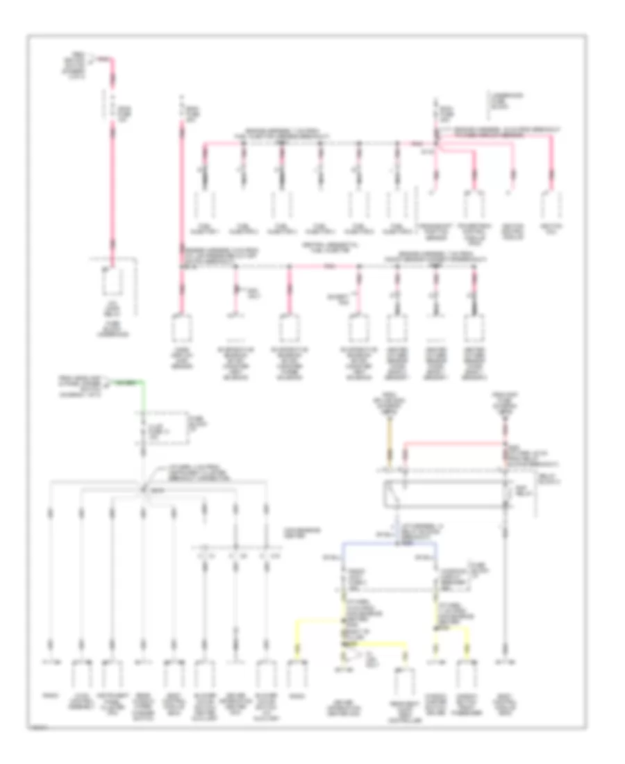
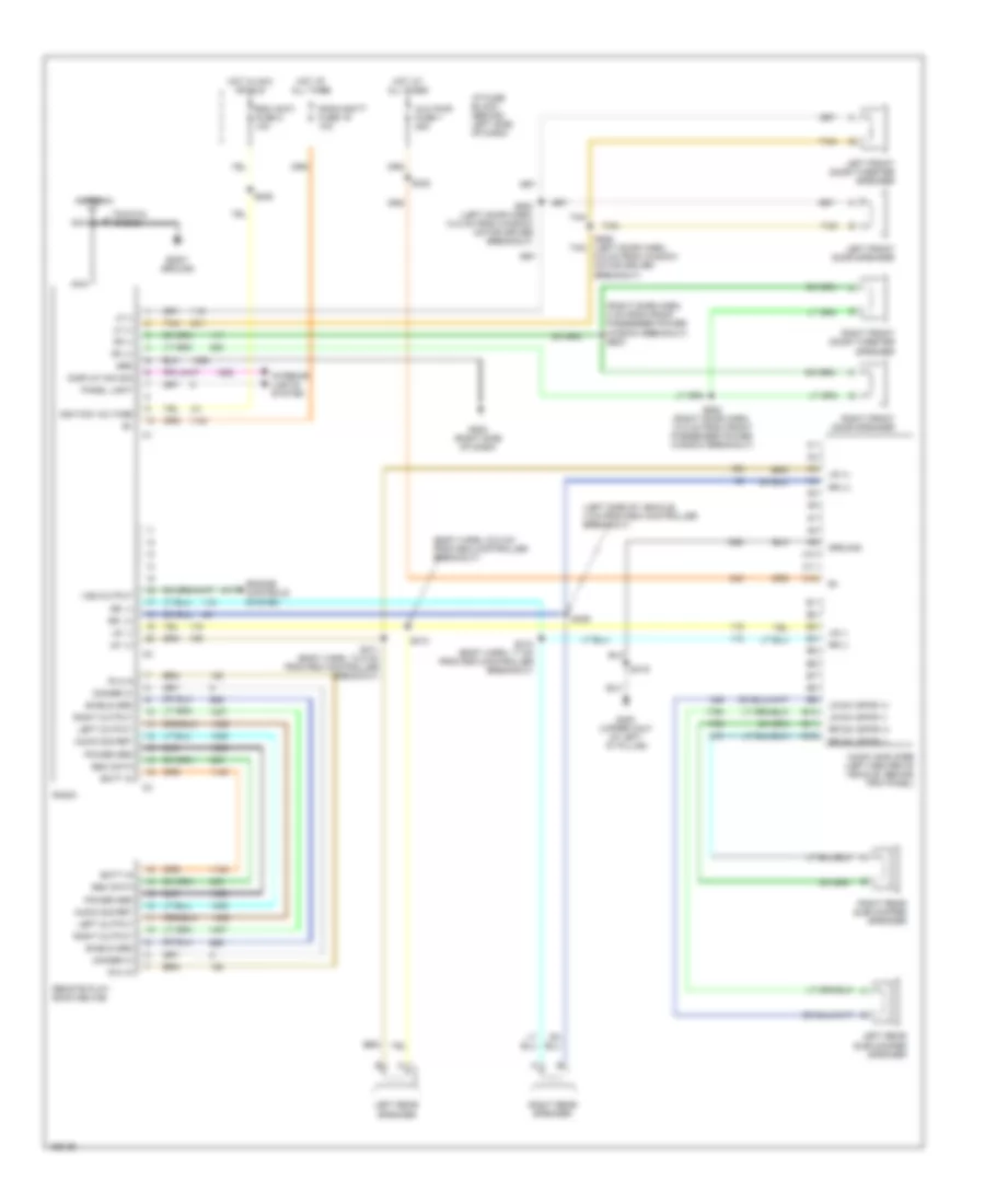
Heater Wiring Diagram for Chevrolet Astro 2002
 https://portal-diagnostov.com/license.html
Automotive Electricians Portal FZCO
Automotive Electricians Portal FZCO
https://portal-diagnostov.com/license.html
https://portal-diagnostov.com/license.html
Automotive Electricians Portal FZCO
Automotive Electricians Portal FZCOList of elements for Heater Wiring Diagram for Chevrolet Astro 2002:
- (forward lamp harn, 8 cm from right headlamp breakout)
- (not used)
- 17 cm from underhood fuse block)
- A/c relay
- Air temperature actuator (behind right side of dash, left side of air duct)
- Auxiliary heater blower motor
- Auxiliary heater blower motor resistor (left side of vehicle, behind "b" pillar)
- Auxiliary heater blower motor switch
- B red
- Bi-lv
- Blend
- Blower motor resistor assembly (behind coolant recovery reservoir, on right front fender)
- Convenience center (behind left kick panel)
- Coolant bypass valve solenoid (behind receiver/ drier)
- Def
- Front blower motor
- Frt hvac fuse 30a
- G100 (right radiator support)
- G104 (lower left side of evaporative housing)
- G200 (right front "a" pillar)
- G301 (above the rear heater, towards rear of vehicle)
- Heat
- Hot at all times
- Hot in run
- Htr-a/c fuse 12 20a
- Hvac control assembly
- I/p fuse block (behind left side of dash)
- Interior lights system
- Med
- Off
- Rr htr a/c fuse 30a
- S100
- S111 (engine harn, 17 cm from underhood fuse block)
- S224 (dash harn. 17 cm from body control module breakout)
- S229 (dash harn, 4 cm from air temp actuator breakout)
- Tan
- Underhood fuse block (left side of firewall)
- Vent
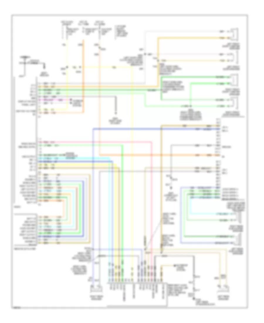
Manual A/C Wiring Diagram for Chevrolet Astro 2002
 https://portal-diagnostov.com/license.html
Automotive Electricians Portal FZCO
Automotive Electricians Portal FZCO
https://portal-diagnostov.com/license.html
https://portal-diagnostov.com/license.html
Automotive Electricians Portal FZCO
Automotive Electricians Portal FZCOList of elements for Manual A/C Wiring Diagram for Chevrolet Astro 2002:
- 11 cm from oil pressure switch breakout)
- 17 cm from underhood fuse block)
- A/c comp fuse 10a
- A/c comp relay
- A/c compressor clutch
- A/c compressor clutch diode (in underhood fuse block)
- A/c enable relay
- A/c high pressure switch (rear of a/c comp)
- A/c low press
- A/c low pressure switch (on a/c accumulator)
- A/c relay
- A/c request
- Air temperature actuator (behind right side of dash, left side of air duct)
- Auxiliary a/c blower motor
- Auxiliary a/c blower motor resistor (left rear of vehicle, near "d" pillar)
- Auxiliary a/c blower motor switch
- Auxiliary heater blower motor
- Auxiliary heater blower motor resistor (left side of vehicle, below "b" pillar)
- Auxiliary heater blower motor switch
- B red
- Bi-lv
- Blend
- Blower motor resistor assembly (behind coolant recovery reservoir, on right front fender)
- C10
- Convenience center (behind left kick panel)
- Coolant bypass valve solenoid (behind receiver/ drier)
- Def
- Front blower motor
- Frt hvac fuse 30a
- G100 (right radiator support)
- G104 (lower left side of evap housing)
- G200 (right front "a" pillar)
- G301 (above the rear heater, towards rear of vehicle)
- G404 (left "d" pillar)
- Heat
- Hot at all times
- Hot in run
- Hot in run or start
- Htr-a/c fuse 12 20a
- Hvac control assembly
- I/p fuse block (behind left side of dash)
- Ign-e fuse 10a
- Interior lights system
- Max
- Med
- Norm
- Off
- Pnk
- Powertrain control module (below underhood fuse block, on left side of firewall)
- Rr htr a/c fuse 30a
- S100 (forward lamp harn, 8 cm from right headlamp breakout)
- S111 (engine harn, 17 cm from underhood fuse block)
- S224 (dash harn. 17 cm from body control module breakout)
- S229 (dash harn, 4 cm from air temp actuator breakout)
- Tan
- Underhood fuse block (left side of firewall)
- Vent
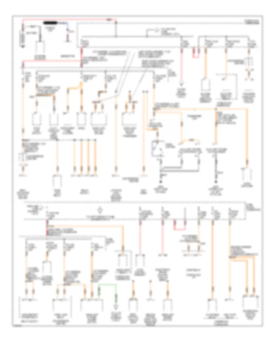
ANTI-LOCK BRAKES
Anti-lock Brake Wiring Diagrams for Chevrolet Astro 2002
 https://portal-diagnostov.com/license.html
Automotive Electricians Portal FZCO
Automotive Electricians Portal FZCO
https://portal-diagnostov.com/license.html
https://portal-diagnostov.com/license.html
Automotive Electricians Portal FZCO
Automotive Electricians Portal FZCOList of elements for Anti-lock Brake Wiring Diagrams for Chevrolet Astro 2002:
- (under left side of dash) data link connector (dlc)
- Abs fuse 60a
- Abs ind
- Brake fluid lvl sw
- Brake fuse 18 10a
- Brake pressure differential switch (on brake pressure modulator valve assembly)
- Brake sw output
- Breakout)
- Computer data lines system
- Cruise control system
- Electronic brake control module (ebcm) (on left front side of frame)
- Fuse output
- G101 (left front radiator support)
- G106 (left rear of engine)
- Ground
- Hot at all times
- Hot in run
- I/p fuse block (behind left side of dash)
- Instrument panel cluster
- Left front wheel speed sensor
- Lf whl spd sens ret
- Lf whl spd sens sig
- Nca
- Power distribution system
- Powertrain control module (pcm) (left side of engine compt)
- Radio batt fuse 19 10a
- Red
- Rf whl spd sens ret
- Rf whl spd sens sig
- Right front wheel speed sensor
- S110
- S127
- Serial data
- Splice pack sp261 (behind left side of dash)
- Stop lamp switch (above brake pedal)
- Tan
- Underhood fuse block (on left side of firewall)
- Vehicle speed out
- Vss
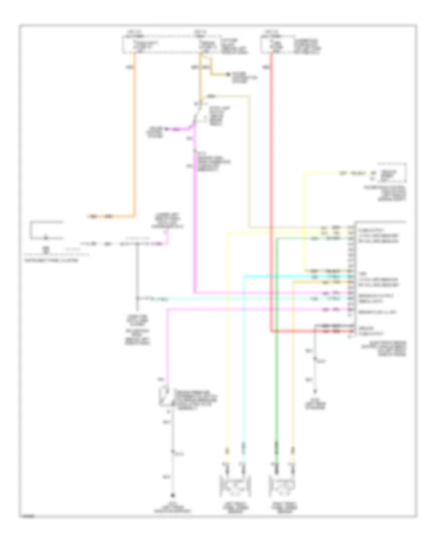
ANTI-THEFT
Anti-theft Wiring Diagram for Chevrolet Astro 2002
 https://portal-diagnostov.com/license.html
Automotive Electricians Portal FZCO
Automotive Electricians Portal FZCO
https://portal-diagnostov.com/license.html
https://portal-diagnostov.com/license.html
Automotive Electricians Portal FZCO
Automotive Electricians Portal FZCOList of elements for Anti-theft Wiring Diagram for Chevrolet Astro 2002:
- 12v ref
- A12
- Body control module (above radio)
- C201
- Class 2 serial data c1
- G107 (left rear of engine, next to knock sensor)
- Gauges fuse 4 10a
- Ground
- Hot at all times
- Hot in run or start
- I/p fuse block (behind left side of dash)
- Ignition
- Instrument panel cluster
- Low ref
- Passlock sensor (in steering column, near lock cylinder)
- Passlock sig
- Pnk
- Power distribution system
- Powertrain control module (below underhood fuse block, on left side of firewall)
- Radio batt fuse 19 10a
- S213
- S225
- S330
- Security hall effect sensor
- Security indicator
- Serial data
- Splice pack sp261 (i/p harn, behind data link connector)
- Tamper hall effect sensor
- Tbc fuse 15 10a
BODY COMPUTER
Body Computer Wiring Diagrams for Chevrolet Astro 2002
 https://portal-diagnostov.com/license.html
Automotive Electricians Portal FZCO
Automotive Electricians Portal FZCO
https://portal-diagnostov.com/license.html
https://portal-diagnostov.com/license.html
Automotive Electricians Portal FZCO
Automotive Electricians Portal FZCOList of elements for Body Computer Wiring Diagrams for Chevrolet Astro 2002:
- 12v ref
- 5v ref
- A10
- A11
- A12
- Acc
- Ambient light sensor (on top left center of dash)
- Ambient light sensor sig
- Anti-theft system
- B10
- B11
- B12
- B7 right turn signal lmp sup volt
- Battery positive voltage
- Body control module (bcm) (above radio)
- Class 2 serial data
- Class 2 serial data sig
- Computer data lines system
- Courtesy lamp low ctrl
- Courtesy lamp on sig
- Courtesy lamp relay ctrl
- Cruise fuse 6 10a
- Door lock ctrl
- Door locks system
- Door unlock ctrl
- Driver door jamb switch sig
- Driver door unlock relay ctrl
- Drl relay ctrl
- Exterior lights system
- G107 (left rear of engine block)
- G110 (left side of firewall, behind battery)
- Gmcm serial data
- Ground
- Guages fuse 4 10a
- Headlamp off sig
- Headlamp relay coil sup volt
- Headlamp sw flash-to-pass
- Headlights system
- High beam sig
- Horn relay ctrl
- Horns system
- Hot at all times
- Hot in run
- Hot in run or start
- I/p fuse block
- I/p lamp sullpy voltage
- Ignition 1 voltage
- Ignition 3 voltage
- Ignition switch
- Instrument cluster system
- Interior lamp defeat sw sig
- Interior lights system
- Key in ignition switch sig
- Led dimming signal
- Left turn signal lmp sup volt
- Lift gate courtesy lamp ctrl
- Lock
- Low ref
- Off
- Park brake switch (on parking brake assembly)
- Park brake switch sig
- Park lamp relay ctrl
- Pass door jamb switch sig
- Pnk
- Power distribution system (rap)
- Rap relay coil ctrl
- Remote keyless entry circuit
- Run
- S201
- S206
- S213
- S225
- S251 (in i/p harn, 7" from lower steering column connector)
- S330
- Seat belt switch sig
- Security system sensor sig
- Side door jamb sw sig
- Start
- Tbc fuse 15 10a
- Tow/haul switch sig
- Transmission system
- Trunk release relay ctrl
- Trunk, tailgate, fuel doors system
- Vehicle speed sensor sig
- Warning sytems
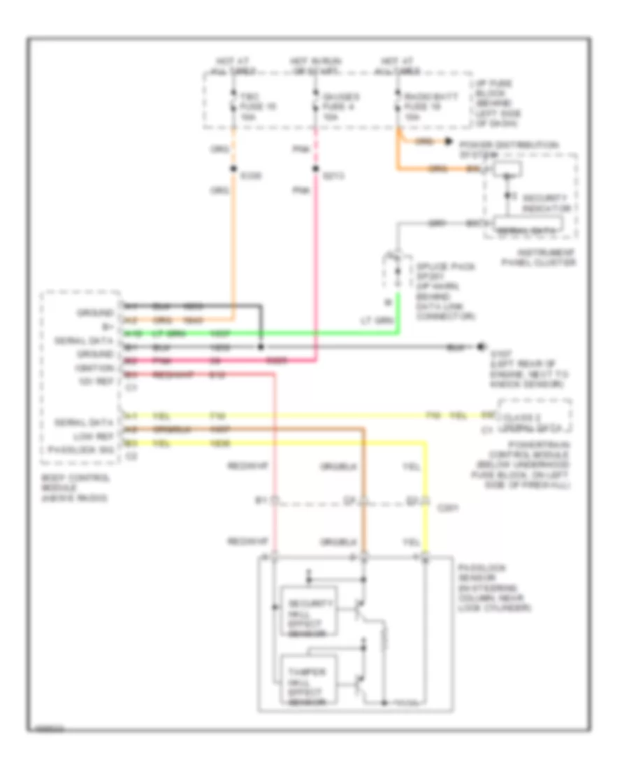
COMPUTER DATA LINES
Computer Data Lines for Chevrolet Astro 2002
 https://portal-diagnostov.com/license.html
Automotive Electricians Portal FZCO
Automotive Electricians Portal FZCO
https://portal-diagnostov.com/license.html
https://portal-diagnostov.com/license.html
Automotive Electricians Portal FZCO
Automotive Electricians Portal FZCOList of elements for Computer Data Lines for Chevrolet Astro 2002:
- A12
- Aux power fuse 7 25a
- Body control module (above radio)
- Convenience center (left of i/p fuse block)
- Data clss 2
- Data link connector (dlc) (under left side of dash)
- Driver information center
- Electronic brake control module (ebcm) (on left front side of frame, left of transmission)
- G105 (front of engine, near thermostat housing)
- G110 (left side of firewall, above battery)
- Hot at all times
- I/p fuse block
- Inflatable restraint sensing & diagnostic module (under driver's seat)
- Instrument panel cluster
- Powertrain control module (below underhood fuse block, on left side of firewall)
- S117
- S204
- S206
- S210
- Splice pack sp261 (strapped on dash harn, behind data link connector)
- Transfer case shift control module (behind left kick panel)
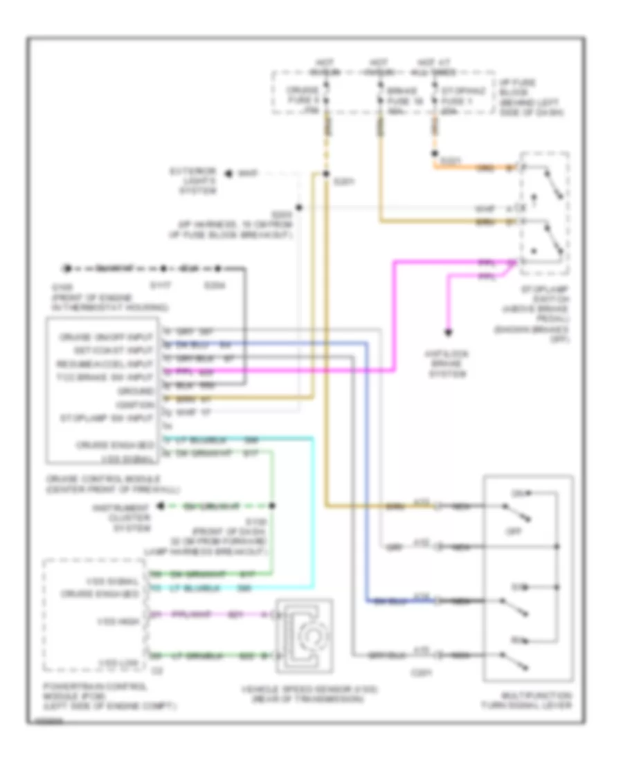
CRUISE CONTROL
Cruise Control Wiring Diagram for Chevrolet Astro 2002
 https://portal-diagnostov.com/license.html
Automotive Electricians Portal FZCO
Automotive Electricians Portal FZCO
https://portal-diagnostov.com/license.html
https://portal-diagnostov.com/license.html
Automotive Electricians Portal FZCO
Automotive Electricians Portal FZCOList of elements for Cruise Control Wiring Diagram for Chevrolet Astro 2002:
- (shown brakes off)
- A12
- A13
- A14
- A15
- Antilock brake system
- Brake fuse 18 10a
- C201
- Cruise control module (center front of firewall)
- Cruise engaged
- Cruise fuse 6 10a
- Cruise on/off input
- Exterior lights system
- G105 (front of engine in thermostat housing)
- Ground
- Hot at all times
- Hot in run
- I/p fuse block (behind left side of dash)
- Ignition
- Instrument cluster system
- Multifunction turn signal lever
- Nca
- Off
- Powertrain control module (pcm) (left side of engine compt)
- R/a
- Resume/accel input
- S/c
- S117
- S130 (front of dash, 32 cm from forward lamp harness breakout)
- S200 (i/p harness, 16 cm from i/p fuse block breakout)
- S201
- S204
- S221
- Set/coast input
- Stop/haz fuse 1 20a
- Stoplamp sw input
- Stoplamp switch (above brake pedal)
- Tcc brake sw input
- Vehicle speed sensor (vss) (rear of transmission)
- Vss high
- Vss low
- Vss signal
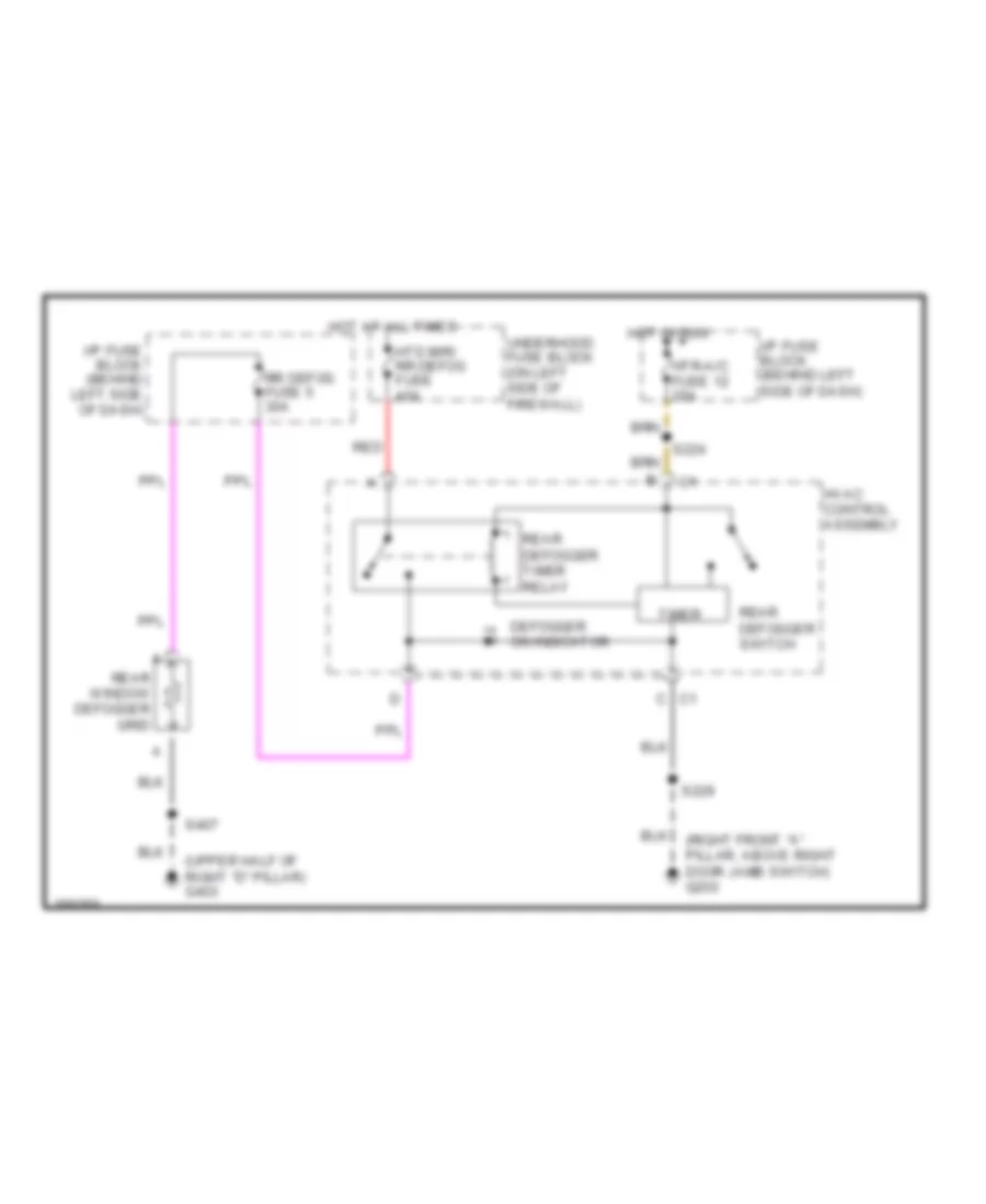
DEFOGGERS
Defogger Wiring Diagram for Chevrolet Astro 2002
 https://portal-diagnostov.com/license.html
Automotive Electricians Portal FZCO
Automotive Electricians Portal FZCO
https://portal-diagnostov.com/license.html
https://portal-diagnostov.com/license.html
Automotive Electricians Portal FZCO
Automotive Electricians Portal FZCOList of elements for Defogger Wiring Diagram for Chevrolet Astro 2002:
- (right front "a" pillar, above right door jamb switch) g200
- (upper half of right "d" pillar) g403
- C1 c
- Defogger on indicator
- Hot at all times
- Hot in run
- Htd mir/ rr-defog fuse 40a
- Htr-a/c fuse 12 20a
- Hvac control assembly
- I/p fuse block (behind left side of dash)
- Rear defogger switch
- Rear defogger timer relay
- Rear window defogger grid
- Red
- Rr defog fuse 5 30a
- S224
- S229
- S407
- Timer
- Underhood fuse block (on left side of firewall)
ENGINE PERFORMANCE
4.3L
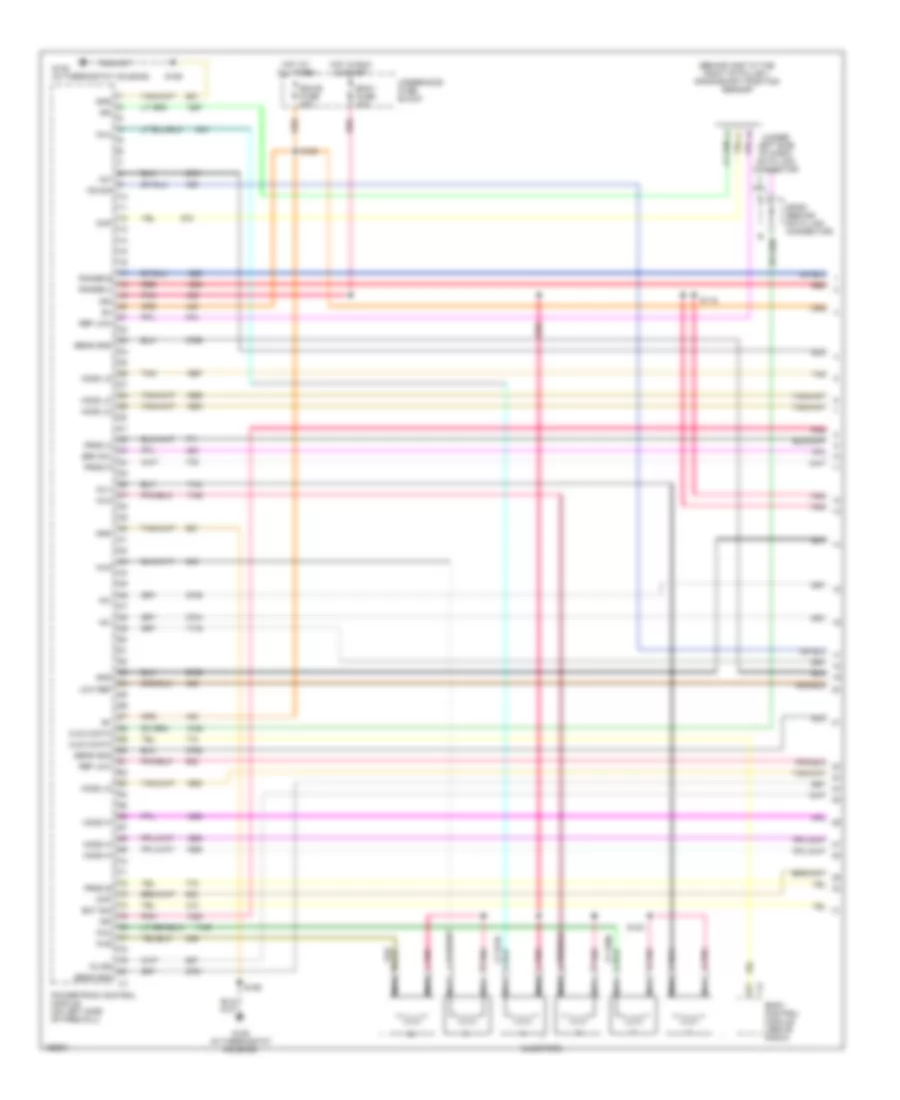
4.3L VIN W, Engine Performance Wiring Diagrams (1 of 4) for Chevrolet Astro 2002
 https://portal-diagnostov.com/license.html
Automotive Electricians Portal FZCO
Automotive Electricians Portal FZCO
https://portal-diagnostov.com/license.html
https://portal-diagnostov.com/license.html
Automotive Electricians Portal FZCO
Automotive Electricians Portal FZCOList of elements for 4.3L VIN W, Engine Performance Wiring Diagrams (1 of 4) for Chevrolet Astro 2002:
- (behind and to the right of pulley) crankshaft position sensor
- (under left side of dash) data link connector
- +5v
- 3-2 ss
- Body control module (above radio)
- Brk sw
- Ckp
- Cls 2 data
- Cmp
- Ecm-b fuse 20a
- Ecm-i fuse 20a
- Ect sig
- G105 (in thermostat housing)
- Gnd
- Ho2s hi
- Ho2s lo
- Hot at all times
- Hot in run & start
- Ign
- Inj1
- Inj2
- Inj3
- Inj4
- Inj5
- Inj6
- Injectors
- Ks sig
- Low ref
- Nca
- Pnk
- Pnk b
- Pnk d
- Pnk e
- Pnk h
- Pnk j
- Pnk l
- Powertrain control module (on left side of firewall)
- Prnd a
- Prnd b
- Prnd p
- Range b
- Range c
- Red
- Ref low
- S109
- S116
- S123
- S155
- Sens gnd
- Sp261 (behind data link connector)
- Tan
- Underhood fuse block
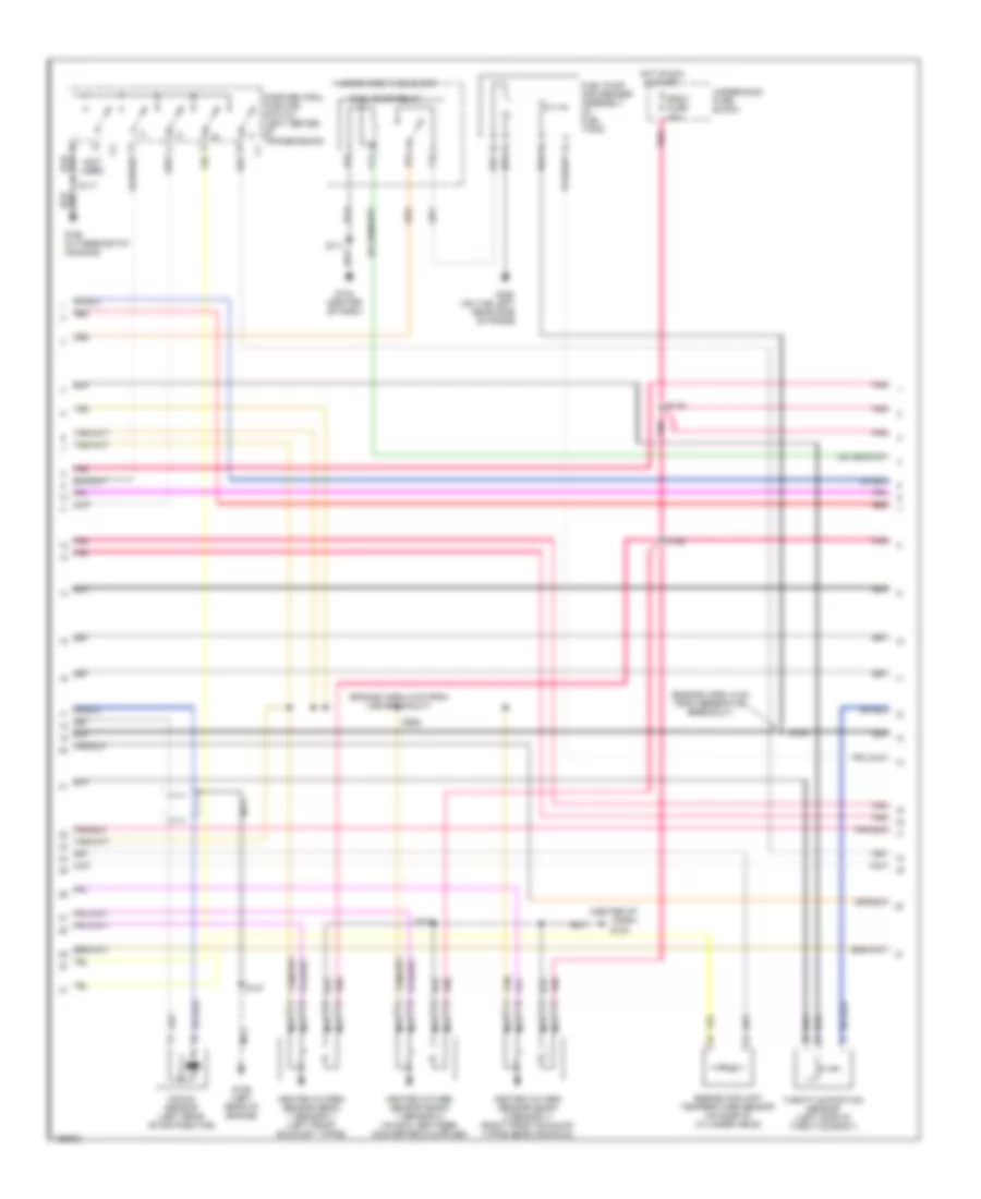
4.3L VIN W, Engine Performance Wiring Diagrams (2 of 4) for Chevrolet Astro 2002
 https://portal-diagnostov.com/license.html
Automotive Electricians Portal FZCO
Automotive Electricians Portal FZCO
https://portal-diagnostov.com/license.html
https://portal-diagnostov.com/license.html
Automotive Electricians Portal FZCO
Automotive Electricians Portal FZCOList of elements for 4.3L VIN W, Engine Performance Wiring Diagrams (2 of 4) for Chevrolet Astro 2002:
- (center of dash)
- (engine harn, 6 cm from generator breakout)
- (engine harn, 6 cm from vss breakout)
- (not used)
- Eng-1 fuse 20a
- Engine coolant temperature sensor (on side of cylinder head)
- Fuel pump and sender assembly (in fuel tank)
- Fuel pump relay
- G104
- G104 (center of dash)
- G105 (in thermostat housing)
- G106 (left rear of engine)
- G302 (on the left rear side of frame
- Heated oxygen sensor (bank 1 sensor 1) (left front exhaust y-pipe)
- Heated oxygen sensor (bank 1 sensor 2) (on exh, between converter & muffler)
- Heated oxygen sensor (bank 2 sensor 1) (right front exhaust y-pipe near manifold)
- Hot in run & start
- Knock sensor (left rear of distributor)
- Nca
- Park/neutral position switch (left center of transmission)
- Pnk
- Red
- S117
- S119
- S124
- S126
- S127
- S154
- S262
- Tan
- Throttle position sensor (left side of throttle body)
- Underhood fuse block
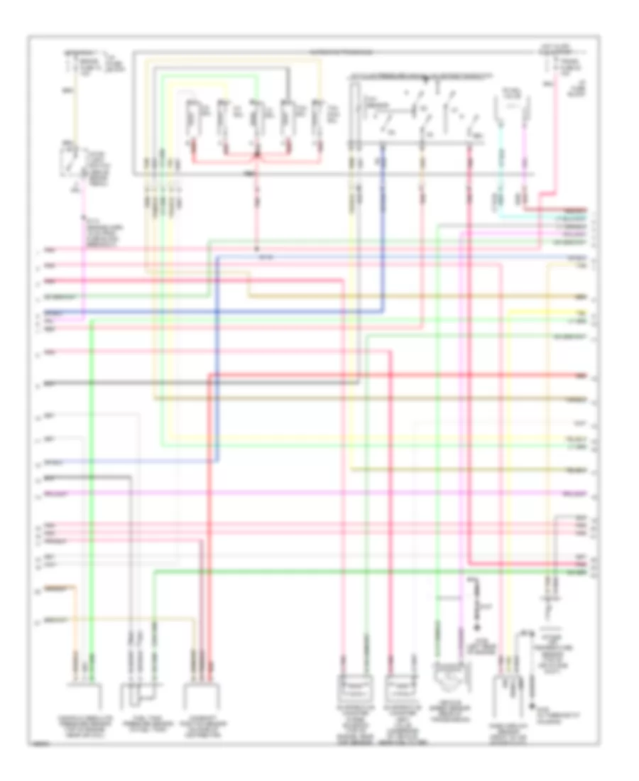
4.3L VIN W, Engine Performance Wiring Diagrams (3 of 4) for Chevrolet Astro 2002
 https://portal-diagnostov.com/license.html
Automotive Electricians Portal FZCO
Automotive Electricians Portal FZCO
https://portal-diagnostov.com/license.html
https://portal-diagnostov.com/license.html
Automotive Electricians Portal FZCO
Automotive Electricians Portal FZCOList of elements for 4.3L VIN W, Engine Performance Wiring Diagrams (3 of 4) for Chevrolet Astro 2002:
- 1-2 sol
- 2-3 sol
- 3-2 sol
- A red
- A/t fluid pressure manual valve position switch
- Air temperature sensor (top of air intake duct)
- Automatic transaxle
- B red
- Brake fuse 18 10a
- Camshaft position sensor (on side of distributor)
- Evaporative canister purge solenoid (top of engine, near map sensor)
- Evaporative canister vent valve (underside of vehicle, near fuel filter)
- Fuel tank pressure sensor (in fuel tank)
- G105 (in thermostat housing)
- G106 (left rear of engine)
- Gnd
- Hot in off run & start
- Hot in run
- I/p fuse block
- Ign
- Intake
- Manifold absolute pressure sensor (top of engine, near ign coil)
- Mass airflow sensor (front of air intake duct)
- N pnk
- P red
- Pc sol valve
- Pnk
- Pnk a
- Pnk c
- Red
- Red/
- Rev
- S112 (engine harn 15 cm from fuse block breakout)
- S115
- S117
- S127
- Signal
- Stop- light switch (above brake pedal)
- Tan
- Tan b
- Tcc pwm sol
- Tcc sol
- Tft sensor
- Trans fuse 20 10a
- Vehicle speed sensor (rear of transmission)
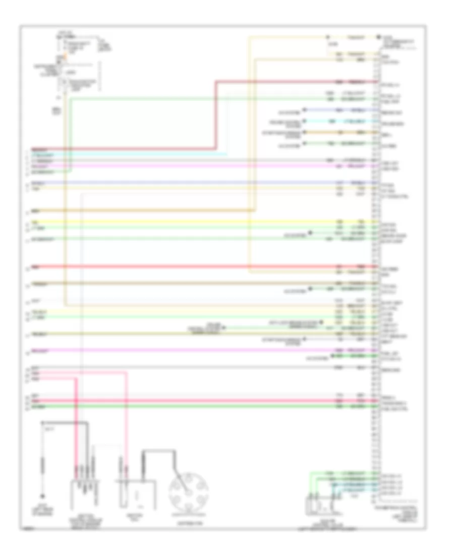
4.3L VIN W, Engine Performance Wiring Diagrams (4 of 4) for Chevrolet Astro 2002
 https://portal-diagnostov.com/license.html
Automotive Electricians Portal FZCO
Automotive Electricians Portal FZCO
https://portal-diagnostov.com/license.html
https://portal-diagnostov.com/license.html
Automotive Electricians Portal FZCO
Automotive Electricians Portal FZCOList of elements for 4.3L VIN W, Engine Performance Wiring Diagrams (4 of 4) for Chevrolet Astro 2002:
- 1-2 ss
- 2-3 ss
- A/c clu
- A/c req
- A/c system
- Anti-lock brake system (speed signal)
- Coil driver
- Coil wire
- Cruise control system
- Cruise control system (speed signal)
- Cruise eng
- Cyc sw in
- Distributor
- Evap canp
- Evap vent
- Fuel lev
- Fuel pmp
- Fuel sig ctrl
- G105 (in thermostat housing)
- G107 (left rear of engine)
- Gen f
- Gen l
- Gnd
- Hot at all times
- I/p fuse block
- Iac coil hi
- Iac coil lo
- Iat sig
- Ic timing ctrl
- Idle air control valve (left rear of throttle body)
- Ign
- Ign feed
- Ignition coil
- Ignition control module (top of engine) front of coil)
- Instrument panel cluster
- Logic
- Maf sig
- Malfunction indicator lamp
- Map sig
- Mil ctrl
- Pc sol hi
- Pc sol lo
- Pnk
- Pnk a
- Powertrain control module (left side of firewall)
- Prnd c
- Radio batt fuse 19 10a
- Recirc door
- Recirc sw
- Red
- S117
- S155
- Sens gnd
- Starting/charging system
- Tan
- Tcc pwm
- Tcc sol
- Tft sens sig
- Timing
- Tp sig
- Trans rng a
- Vss high
- Vss low
- Vss out
EXTERIOR LIGHTS
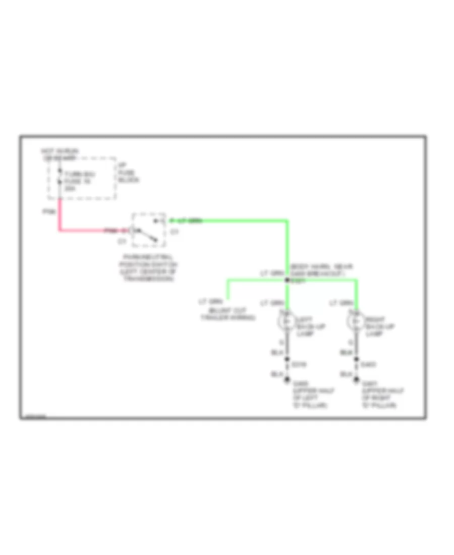
Back-up Lamps Wiring Diagram for Chevrolet Astro 2002
 https://portal-diagnostov.com/license.html
Automotive Electricians Portal FZCO
Automotive Electricians Portal FZCO
https://portal-diagnostov.com/license.html
https://portal-diagnostov.com/license.html
Automotive Electricians Portal FZCO
Automotive Electricians Portal FZCOList of elements for Back-up Lamps Wiring Diagram for Chevrolet Astro 2002:
- (body harn, near g400 breakout) s321
- G400 (upper half of left "d" pillar)
- G401 (upper half of right "d" pillar)
- Hot in run or start
- I/p fuse block
- Left back-up lamp
- Park/neutral position switch (left center of transmission)
- Pnk
- Right back-up lamp
- S319
- S403
- Turn b/u fuse 16 20a
Exterior Lamps Wiring Diagram for Chevrolet Astro 2002
 https://portal-diagnostov.com/license.html
Automotive Electricians Portal FZCO
Automotive Electricians Portal FZCO
https://portal-diagnostov.com/license.html
https://portal-diagnostov.com/license.html
Automotive Electricians Portal FZCO
Automotive Electricians Portal FZCOList of elements for Exterior Lamps Wiring Diagram for Chevrolet Astro 2002:
- (body harn, near right rear door breakout) s401
- (i/p harn, near instrument cluster conn breakout)
- A11
- Auto
- Back-up lamps circuit
- Body control module (above radio)
- C201
- Center high mounted stop lamp (chmsl)
- Chmsl resistor (on left kick panel)
- Convenience center (near left kick panel)
- Cruise control system
- G100 (right front radiator support)
- G101 (left front radiator support)
- G105 (front of engine, near thermostat housing)
- G110 (left side of firewall, above battery)
- G116 (left side of firewall, above battery)
- G400 (upper half of left "d" pillar)
- G401 (upper half of right "d" pillar)
- Haz sw
- Hazard
- Head
- Headlamp & panel dimmer switch
- Hot at all times
- Hot in run or start
- I/p fuse block
- Instru- ment panel cluster
- Interior light system
- Left front marker lamp
- Left front park/ turn signal lamp
- Left rear marker lamp
- Left tail/ stop/ turn signal lamp
- Left turn ind.
- Left turn switch
- License lamp
- Lt turn sig in
- Multi- function turn signal lever
- Nca
- Normal
- Off
- Park
- Park lamp relay (in conven- ience center)
- Park lps fuse 9 20a
- Pl input
- Pl rly enable
- Pnk
- Red
- Right front marker lamp
- Right front park/ turn signal lamp
- Right rear marker lamp
- Right tail/ stop/ turn signal lamp
- Right turn ind.
- Right turn switch
- Rt turn sig in
- S101 (forward lamp harn, 4 cm from right park/ turn lamp breakout)
- S102 (forward lamp harness, 4 cm from left headlamp breakout)
- S103 (forward lamp harn, 3 cm from left headlamp breakout)
- S104
- S204
- S206
- S211 (i/p harn, 6 cm from instrument cluster conn breakout)
- S212 (i/p harn, 11.5 cm from i/p to steering column conn breakout)
- S217
- S250
- S256
- S303
- S319
- S320 (body harn, near g400 breakout)
- S400 (body harn, near chmsl breakout)
- S402 (body harn, near right rear door breakout)
- S403
- Sound systems
- Stop lamp switch (above brake pedal)
- Stop/ haz fuse 1 20a
- Tn sw
- Turn signal/ hazard flasher module (in convenience center)
- Turn- b/u fuse 16 20a
- Underhood fuse/relay center (on left side of firewall)
- Upfit- bat maxi fuse p8 30a
GROUND DISTRIBUTION
Ground Distribution Wiring Diagram (1 of 2) for Chevrolet Astro 2002
 https://portal-diagnostov.com/license.html
Automotive Electricians Portal FZCO
Automotive Electricians Portal FZCO
https://portal-diagnostov.com/license.html
https://portal-diagnostov.com/license.html
Automotive Electricians Portal FZCO
Automotive Electricians Portal FZCOList of elements for Ground Distribution Wiring Diagram (1 of 2) for Chevrolet Astro 2002:
- (vanity mirror harness, 8 cm from left vanity mirror breakout)
- 4 cm from breakout toward top of vehicle) s315
- A/c coil diode 1
- A/c compressor clutch
- A/c compressor low pressure cut-off switch
- A/t shift lock control solenoid
- A16
- Air temperature sensor- (outside)
- Axiliary rear a/c relay
- Blower motor switch- a/c auxiliary
- Blower motor switch- heater auxiliary
- Body control module (bcm)
- C10
- C201
- C303
- Center high mounted stop lamp (chmsl) resistor
- Convenience center
- Coolant bypass valve solenoid
- Cruise control module (ccm)
- Data link connector (dlc)
- Door lock switch- driver
- Driver information center (dic)
- Driver seat adjuster switch
- E15
- E16
- Fuel pump relay
- G104 (behind center of dash)
- G105 (front of engine, in thermostat housing)
- G107 (left rear of engine block)
- G110 (left side of firewall, behind battery)
- Headlamp & panel dimmer switch
- Heated oxygen sensor (ho2s) bank 1 sensor 1
- Heated oxygen sensor (ho2s) bank 1 sensor 2
- Heated oxygen sensor (ho2s) bank 2 sensor 1
- I/p fuse block
- Ignition control module (icm)
- Ignition key alarm switch
- Ignition switch
- Instrument panel cluster (ipc)
- Mass air flow (maf) sensor
- Nca
- Outside rearview mirror switch
- Park/neutral position (pnp) switch
- Powertrain control module (pcm)
- Rear seat audio (rsa) controller (if equipped)
- Relay block 1
- Relay block 2
- S111 (engine harness, 17 cm from fuse block-underhood breakout)
- S124 (engine harness, 11.5 cm from oil pressure switch breakout)
- S204 (i/p harness, 10 cm from c201 in lower half of steering column)
- S206 (i/p harness, 4 cm from c201, in lower half of steering column)
- S225
- S236
- S325
- Starter relay
- Steering column ground- molded
- Tow/ haul switch
- Transfer case shift control module
- Turn signal/ hazard flasher module
- Underhood fuse block
- Upfitter accy relay
- Vanity mirror lamp- left
- Vanity mirror lamp- right
- Window master switch- driver
- Windshield wiper motor & module
Ground Distribution Wiring Diagram (2 of 2) for Chevrolet Astro 2002
 https://portal-diagnostov.com/license.html
Automotive Electricians Portal FZCO
Automotive Electricians Portal FZCO
https://portal-diagnostov.com/license.html
https://portal-diagnostov.com/license.html
Automotive Electricians Portal FZCO
Automotive Electricians Portal FZCOList of elements for Ground Distribution Wiring Diagram (2 of 2) for Chevrolet Astro 2002:
- (behind bottom of left "b" pillar)
- (front of left rear wheelwell)
- (left kick panel)
- (left rear of vehicle)
- (on the left rear side of frame)
- (right front radiator support)
- (right kick panel)
- (upper half of left "d" pillar)
- (upper half of right "d" pillar)
- 15 cm from vehicle speed sensor)
- Air temperature actuator
- Audio amplifier
- Auxiliary power- outlet- front 1
- Auxiliary power- outlet- front 2
- Battery
- Blower motor resistor assembly
- Blower motor- a/c auxiliuary
- Blower motor- heater auxiliuary
- Brake pressure differential switch
- C112
- C302
- C333
- Center high mounted stop lamp (chmsl)
- Cigar lighter
- Conven- ience center
- Courtesy reading lamp- center
- Door lock relay
- Door lock switch- front passenger
- Driver door unlock relay
- Electronic brake control module (ebcm)
- Engine cover ground
- Front courtesy reading lamp
- Fuel pump & sender assembly
- Fuse block- underhood
- G100
- G101 (left front radiator support)
- G102 (left side radiator support)
- G103 (lower right side of engine block)
- G106 (left rear of engine)
- G200
- G300
- G301
- G302
- G303
- G400
- G401
- G403
- G404
- Garage door opener
- Headlamps relay
- Horn- right
- Hvac control assembly
- I/p compartment lamp
- Inflatable restraint sensing & diagnostic module
- Knock sensor (ks) shield
- Left back-up lamp
- Left front park/turn signal lamp
- Left horn
- Left marker lamp
- Left tail/ stop & turn lamp
- License lamp
- Liftglass lock/ unlock relay
- Liftglass release actuator
- Nca
- Overhead console
- Radio
- Reading lamps (1 of 4)
- Rear auxiliary power outlet
- Rear door jamb switch
- Rear window defogger grid
- Rear window washer fluid pump
- Rear window wiper/ washer module
- Rear window wiper/ washer switch
- Relay block 1
- Remote control door lock receiver
- Right backup lamp
- Right front park/ turn signal lamp
- Right rear side marker lamp
- Right tail/stop & turn lamp
- S100 (forward lamp harness, 8 cm from right head- lamp breakout)
- S104 (forward lamp harn, 17 cm from left headlamp lamp breakout)
- S110 (engine harn, 24 cm from fuse block-underhood breakout)
- S127 (engine harness, 11 cm from park/ neutral position switch)
- S134 (engine harn, 5 cm from knock sensor breakout)
- S229 (i/p harness, 4 cm from air temperature actuator motor breakout, toward right side of dash)
- S234 (i/p cowl harness, 28 cm from cigar lighter connector)
- S319 (body harn, 10 cm from g400 breakout)
- S403 (right rear "d" pillar, 5 cm from right rear door breakout)
- S407 (liftgate body harness, 20 cm from g403 breakout)
- S601 (right door harness, 4 cm from power door lock switch breakout)
- Seat belt buckle switch
- Upfitter connector
- Vehicle speed sensor (vss) shield
- W/ overhead console
- W/o overhead console
- Window switch- front passenger
- Windshield washer fluid pump
HEADLIGHTS
Headlight Wiring Diagram for Chevrolet Astro 2002
 https://portal-diagnostov.com/license.html
Automotive Electricians Portal FZCO
Automotive Electricians Portal FZCO
https://portal-diagnostov.com/license.html
https://portal-diagnostov.com/license.html
Automotive Electricians Portal FZCO
Automotive Electricians Portal FZCOList of elements for Headlight Wiring Diagram for Chevrolet Astro 2002:
- (fwd lamp harn, 10.5 cm from left headlamp breakout)
- (fwd lamp harn, 4 cm from left headlamp breakout)
- 5v ref
- A11
- Ambient light sensor (top center of dash)
- Auto
- Body control module (bcm) (above radio)
- C201
- Composite headlamps
- Daytime running lamps diode (on lower part of left "b" pillar)
- Daytime running lamps relay
- Drl relay crtl
- E10
- E11
- E12
- E13
- Flash to pass
- G101 (left front radiator support)
- G110 (left side of firewall)
- G110 (left side of firewall, above battery)
- Gauges fuse 4 10a
- Head
- Headlamp & panel dimmer switch
- Headlamp relay
- Headlp enable
- Headlp req
- Hi beam sig
- Hot at all times
- Hot in run or start
- I/p fuse block (behind left side of dash)
- Left headlamp
- Left high beam headlamp
- Left low beam headlamp
- Lh hdlp fuse 15a
- Lighting fuse 40a
- Multifunction turn signal lever
- Off
- Park
- Photo cell
- Pnk
- Red
- Relay block 2 (behind left side of dash)
- Rh hdlp fuse 15a
- Right headlamp
- Right high beam headlamp
- Right low beam headlamp
- S105
- S106
- S110
- S131
- S132
- S133
- S206
- S213
- S254 (i/p harn, near lower half of steering column)
- S255 (i/p harn, near left side front of dash)
- S257 (i/p harn, 12.5 cm from instrument cluster breakout)
- S330
- Sealed beam headlamps
- Tan
- Tbc fuse 15 10a
- Underhood fuse block (on left side of firewall)
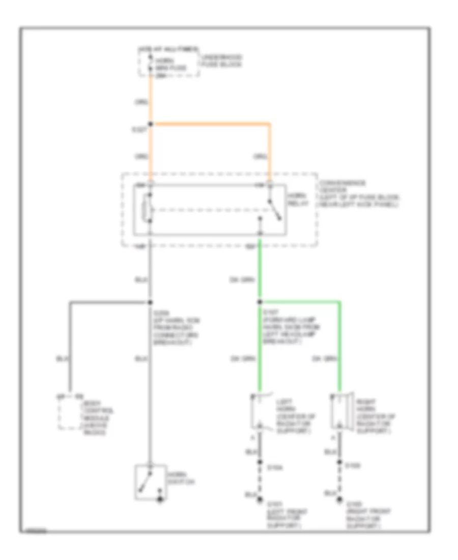
HORN
Horn Wiring Diagram for Chevrolet Astro 2002
 https://portal-diagnostov.com/license.html
Automotive Electricians Portal FZCO
Automotive Electricians Portal FZCO
https://portal-diagnostov.com/license.html
https://portal-diagnostov.com/license.html
Automotive Electricians Portal FZCO
Automotive Electricians Portal FZCOList of elements for Horn Wiring Diagram for Chevrolet Astro 2002:
- C1 body control module (above radio)
- Convenience center (left of i/p fuse block, near left kick panel)
- G100 (right front radiator support)
- G101 (left front radiator support)
- Horn mini fuse 20a
- Horn relay
- Horn switch
- Hot at all times
- Left horn (center of radiator support)
- Right horn (center of radiator support)
- S100
- S104
- S107 (forward lamp harn, 54cm from left headlamp breakout)
- S259 (i/p harn, 5cm from radio connectors breakout)
- S327
- Underhood fuse block
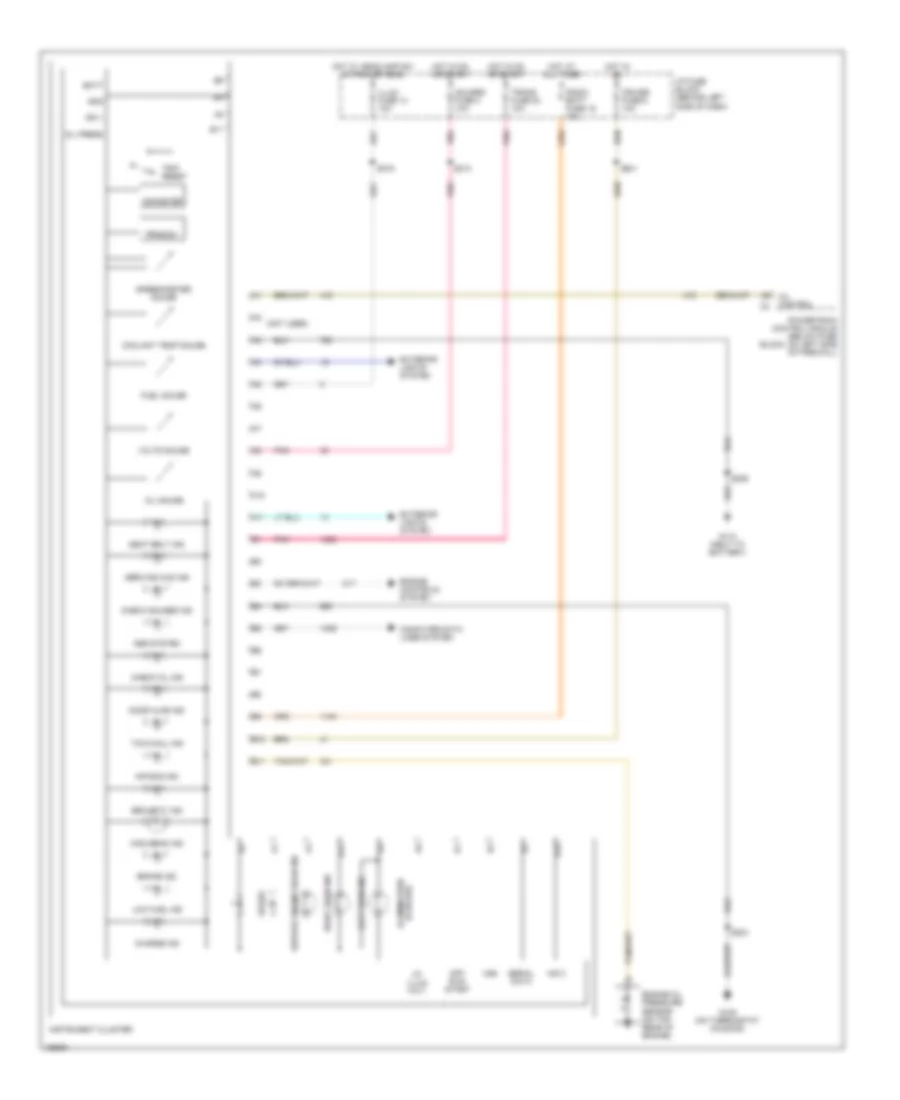
INSTRUMENT CLUSTER
Instrument Cluster Wiring Diagram for Chevrolet Astro 2002
 https://portal-diagnostov.com/license.html
Automotive Electricians Portal FZCO
Automotive Electricians Portal FZCO
https://portal-diagnostov.com/license.html
https://portal-diagnostov.com/license.html
Automotive Electricians Portal FZCO
Automotive Electricians Portal FZCOList of elements for Instrument Cluster Wiring Diagram for Chevrolet Astro 2002:
- (not used)
- A10
- A11
- Abs system
- Air bag ind
- B10
- B11
- Batt
- Brake ind
- Charge ind
- Check gauges ind
- Check oil ind
- Computer data lines system
- Coolant temp gauge
- Cruise fuse 6 10a
- Door ajar ind
- Engine controls system
- Engine oil pressure sensor (on top rear of engine)
- Exterior lights system
- Fuel gauge
- G105 (on thermostat housing)
- G110 (next to battery)
- Gauges fuse 4 10a
- Gnd
- High beam ind
- Hot at all times
- Hot in on
- Hot in on or start
- Hot w/ headlamp sw in park or head
- I/p fuse block (behind left side of dash)
- I/p illum volt
- Ign 1
- Illum fuse 14 10a
- Illumination (6 bulbs)
- Ing 3
- Instrument cluster
- Left turn ind
- Low fuel ind
- Mil control
- Odometer
- Off/ run/ start
- Oil gauge
- Oil press
- Pnk
- Powertrain control module (below fuse block, on left side of firewall)
- Prnd321
- Radio batt fuse 19 10a
- Right turn ind
- S201
- S204
- S206
- S213
- S219
- Seat belt ind
- Security ind
- Serial data
- Service 4wd ind
- Service engine soon ind
- Spare
- Speedometer gauge
- Tow/haul ind
- Trans fuse 20 10a
- Trip reset
- Volts gauge
- Vss
Overhead Console Wiring Diagram for Chevrolet Astro 2002
 https://portal-diagnostov.com/license.html
Automotive Electricians Portal FZCO
Automotive Electricians Portal FZCO
https://portal-diagnostov.com/license.html
https://portal-diagnostov.com/license.html
Automotive Electricians Portal FZCO
Automotive Electricians Portal FZCOList of elements for Overhead Console Wiring Diagram for Chevrolet Astro 2002:
- (i/p harness, 32 cm from i/p fuse block breakout) s130
- (overhead console harn, 18 cm from driver information center connector)
- Ambient air temperature sensor (center of core support, in front of radiator)
- C303
- Computer data lines system
- Driver information center
- G105 (front of engine, near thermostat housing)
- Garage door opener circuit
- Hot in accy or run
- I/p fuse block (behind left side of dash)
- Instrument cluster
- Interior lights system
- Radio accy fuse 2 10a
- Red
- S117
- S204
- S246
- S315 (w/ rear radio controls only)
- S328 (w/ rear radio controls)
- S341
- Vss
INTERIOR LIGHTS
Courtesy Lamps Wiring Diagram (1 of 2) for Chevrolet Astro 2002
 https://portal-diagnostov.com/license.html
Automotive Electricians Portal FZCO
Automotive Electricians Portal FZCO
https://portal-diagnostov.com/license.html
https://portal-diagnostov.com/license.html
Automotive Electricians Portal FZCO
Automotive Electricians Portal FZCOList of elements for Courtesy Lamps Wiring Diagram (1 of 2) for Chevrolet Astro 2002:
- A2 crtsy lmp sig b2 right dr sw b4 left dr sw b6 lmp def sw c3
- A3 courtesy lmp b10 side dr sw b11 rear dr sw b12 b+ lmp rqust b6 park lmp in c2
- A8 interior lmp c1 enable rly
- Body control module (above radio)
- Breakout)
- C302
- Center courtesy/ reading lamps
- Courtesy lamp relay
- Ctsy fuse 3 20a
- Dome lamp
- Driver door jamb switch
- Front courtesy/ reading lamps
- Front dome/ reading lamps
- Front passenger door jamb switch
- G110 (left side of firewall, next to battery)
- G400 (upper half of left "d" pillar)
- Hot at all times
- I/p fuse block (behind left side of dash)
- Inadvertent power relay
- Left courtesy lamp
- Map lights
- Nca
- Overhead console
- Passenger van only
- Pk lps fuse 9 20a
- Pnk
- Reading lamp
- Reading lamp switches
- Rear dome lamp
- Relay block 1 (behind left side of dash, on dlc bracket)
- Right courtesy lamp
- Right step- well lamp
- S206
- S220
- S301 (body harn, 5 cm from courtesy/ reading lamp center breakout)
- S307 (body harn, 5.5 cm from courtesy/ reading lamp center breakout)
- S319
- Side door jamb switch
- W/ console
- W/o console
Courtesy Lamps Wiring Diagram (2 of 2) for Chevrolet Astro 2002
 https://portal-diagnostov.com/license.html
Automotive Electricians Portal FZCO
Automotive Electricians Portal FZCO
https://portal-diagnostov.com/license.html
https://portal-diagnostov.com/license.html
Automotive Electricians Portal FZCO
Automotive Electricians Portal FZCOList of elements for Courtesy Lamps Wiring Diagram (2 of 2) for Chevrolet Astro 2002:
- (i/p harn, 2.5 cm from instrument cluster breakout) s217
- (left door harn, 10.5 cm from power window motor breakout) s503
- (right door harn, 17 cm from power window switch breakout) s605
- (vanity mirror harn, 7.5 cm from left vanity mirror breakout) s236
- (vanity mirror harn, 7.5 cm from left vanity mirror breakout) s237
- Convenience center (left of i/p fuse block, by left kick panel)
- Cover switch
- Dome lamp switch
- Dome lmp defeat switch
- Driver door lock switch
- Driver window master switch
- Exterior lights system
- Front passenger door lock switch
- Front passenger window switch
- G107 (left rear of engine block)
- G110 (left side of firewall, next to battery)
- G200 (right kick panel)
- G400 (upper half of left "d" pillar)
- Headlamp & panel dimmer switch
- I/p compartment lamp
- Left vanity mirror lamp
- Outside rearview mirror switch
- Park lamp switch
- Rear door jamb switch
- Rear seat audio (rsa) controller (on left side of vehicle, behind left "b" pillar)
- Right vanity mirror lamp
- S117
- S206
- S234
- S256
- S315
- S319
- S401 (body harn, 10.5 cm from right rear door breakout)
- S504
- S601
- W/ power mirrors
- W/ rear radio control only
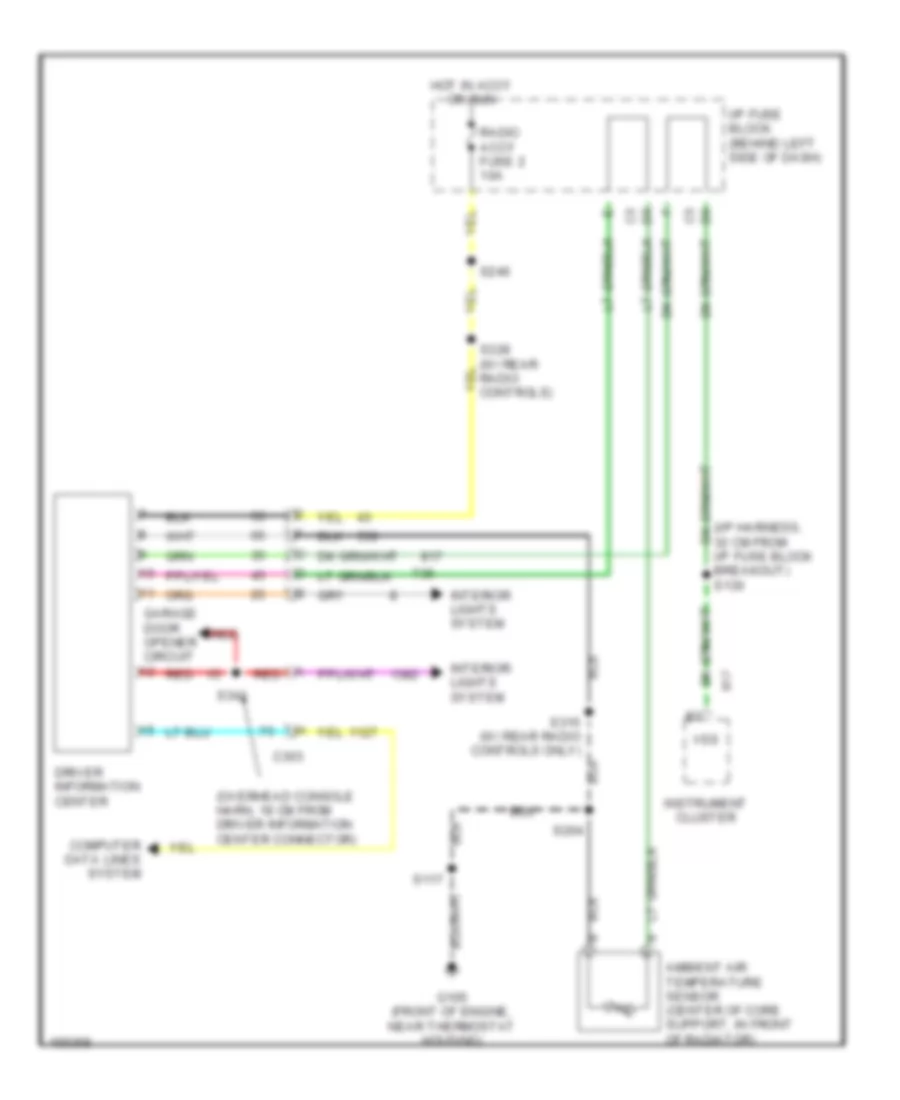
Instrument Illumination Wiring Diagram for Chevrolet Astro 2002
 https://portal-diagnostov.com/license.html
Automotive Electricians Portal FZCO
Automotive Electricians Portal FZCO
https://portal-diagnostov.com/license.html
https://portal-diagnostov.com/license.html
Automotive Electricians Portal FZCO
Automotive Electricians Portal FZCOList of elements for Instrument Illumination Wiring Diagram for Chevrolet Astro 2002:
- (6 bulbs)
- A12
- Auxiliary a/c blower motor switch
- Auxiliary heater blower motor switch
- Body control module (above radio)
- C1 a
- C10
- C5 a
- Convenience center (left of i/p fuse block, by left kick panel)
- Dim stat
- Driver information center (dic)
- G105 (front of engine, on thermostat housing)
- G107 (left rear of engine block)
- G110 (left side of firewall, next to battery)
- G200 (right kick panel)
- Garage door opener
- Headlamp & panel dimmer switch
- Hot at all times
- Hvac control assembly
- I/p fuse block
- I/p fuse block (behind left side of dash)
- Illum fuse 14 10a
- Instrument panel cluster
- Interior lamp dimmer
- Led dim
- Led dim sig
- Park lamps switch
- Pk lps fuse 9 20a
- Radio
- Rear seat audio (rsa) controller (on left side of vehicle, behind "b" pillar)
- Rear window wiper/ washer switch
- Red
- Remote playback device
- S117
- S206
- S219
- S229
- S256
- S315
- S341
- Tan
- W/ rear radio control only
POWER DISTRIBUTION
Power Distribution Wiring Diagram (1 of 3) for Chevrolet Astro 2002
 https://portal-diagnostov.com/license.html
Automotive Electricians Portal FZCO
Automotive Electricians Portal FZCO
https://portal-diagnostov.com/license.html
https://portal-diagnostov.com/license.html
Automotive Electricians Portal FZCO
Automotive Electricians Portal FZCOList of elements for Power Distribution Wiring Diagram (1 of 3) for Chevrolet Astro 2002:
- (eng harn, 3 cm from fuse block-underhood breakout)
- (engine harness, 4 cm from fuse block- underhood breakout) s109
- (i/p harness, 10 cm from bcm connectors breakout)
- (i/p harness, 13cm from fuse block-i/p) s209 red
- (i/p harness, 17 cm from instrument cluster conn breakout)
- (i/p harness, 28 cm from i/p fuse block)
- (i/p harness, in left side front of dash) s210
- (left door harness, 17 cm from power window switch breakout)
- (not used)
- (right door harness, 6 cm from power door lock switch breakout)
- A/c comp fuse 10a
- A/c enable relay
- A12
- Abs fuse 60a
- Atc fuse 20a
- Audio amplifier
- Aux pwr fuse 7 25a
- Auxiliary power outlets-front 1&2
- Auxiliary power outlets-rear
- Auxiliary rear a/c relay
- Batt fuse 50a
- Battery
- Blower motor resistor assembly
- Body control module (bcm)
- Cig ltr fuse 13 20a
- Cigar lighter
- Convenience center
- Ctsy fuse 3 20a
- Data link connector (dlc)
- Door lock relay
- Door lock switch- driver
- Door lock switch- front passenger
- Ecm-b fuse 20a
- Electronic brake control module (ebcm)
- From abs fuse a (diagram 1 of 3)
- Frt hvac fuse 30a
- Fuel pump relay
- Fuse block-
- Fuse block- i/p
- Fuse block- underhood
- Fusible link
- G200 (right side of dash)
- G400 (upper half of left "d" pillar)
- Generator
- Headlamp & panel dimmer switch
- Headlamp dimmer switch
- Headlamps relay
- Horn fuse 20a
- Horn relay
- Htd mir/ rr defog fuse 40a
- Hvac control assembly
- I/p fuse block
- Inadvertent power relay
- Instrument panel cluster
- Liftgate lock/ unlock release switch
- Lighting fuse 40a
- Multi- function turn signal lever
- Nca
- Outside rearview mirror switch
- Park lamp relay
- Passenger van
- Pk lps fuse 9 20a
- Powertrain control module (pcm)
- Pwr accy cb 25a
- Radio
- Radio batt fuse 19 10a
- Rap fuse 40a
- Red
- Relay block 1
- Remote control door lock receiver (rcdlr)
- Rr htr/ac fuse 30a
- S121
- S133
- S221
- S227
- S319
- S322 (left "b" pillar, 4 cm from break- out toward top of vehicle)
- S327
- S500
- S600
- Seat adjuster switch- driver
- Starter solenoid
- Stop lamp switch
- Stop/haz fuse 1 20a
- Tbc fuse 15 10a
- To illum fuse 14 (diagram 3 of 3)
- To lighting fuse (diagram 1 0f 3)
- To rap relay (diagram 3 of 3)
- To upfitter-batt fuse (diagram 2 of 3)
- Transfer case shift control module
- Underhood
- Underhood fuse block
Power Distribution Wiring Diagram (2 of 3) for Chevrolet Astro 2002
 https://portal-diagnostov.com/license.html
Automotive Electricians Portal FZCO
Automotive Electricians Portal FZCO
https://portal-diagnostov.com/license.html
https://portal-diagnostov.com/license.html
Automotive Electricians Portal FZCO
Automotive Electricians Portal FZCOList of elements for Power Distribution Wiring Diagram (2 of 3) for Chevrolet Astro 2002:
- (engine harn, 18 cm from maf sensor breakout)
- (engine harness, 11 cm from fuse block-underhood breakout)
- (i/p harn, 17 cm from bcm connectors breakout)
- (i/p harn, 20 cm from fuse block- i/p)
- (i/p harness, 28 cm from i/p fuse block) s303
- (i/p harness, 38 cm from convenience center) s324
- (i/p harness, 41 cm from headlamp switch connector) s213
- (i/p harness, 7 cm from conn. at lower left of steering column)
- (not used)
- A13
- Acc
- Air bag fuse 10 10a
- Air temperature actuator
- Automatic transmission
- Auxiliary rear a/c relay
- B10
- Body control module (bcm)
- Body control module (ebcm)
- Bottom of left "b" pillar)
- Brake fuse 18 10a
- Convenience center
- Crank fuse 8 10a
- Cruise control module (ccm)
- Cruise control on/off switch
- Cruise fuse 6 10a
- E10
- Electronic brake control module (ebcm)
- From lighting c
- From upfitter-accy fuse (diagram 2 of 3)
- Fuse (diagram 1 of 3)
- Fuse block- i/p
- Fuse block- underhood
- G104 (behind center of dash)
- Gauges fuse 4 10a
- Heater & a/c control module
- Htr-a/c fuse 12 20a
- Ign-a fuse 40a
- Ign-b fuse 40a
- Ignition switch
- Inflatable restraint sensing & diagnostic module (sdm)
- Instrument panel cluster (ipc)
- Lock
- Multi- function turn signal lever
- Multifunction turn signal lever
- Nca
- Off
- Park/ neutral position (pnp) switch
- Park/neutral position & (pnp) switch
- Pnk
- Power- train control module (pcm)
- Rear window wiper/ washer switch
- Red
- Relay block 2
- Rr wiper fuse 23 20a
- Run
- S108
- S111
- S115
- S201
- S203 (i/p harness, toward right side of dash)
- S205
- S224
- S240 (upfitter harn, 30 red cm from convenience center)
- S242 (in upfitter harn, near pnk
- Start
- Starter enable relay
- Stop lamp switch
- To ign-e fuse (diagram 3 of 3)
- To rap relay (diagram 3 of 3)
- To trailer wiring harness
- To upfitter accy relay (diagram 2 of 3)
- Trans fuse 20 10a
- Transfer case shift control module
- Turn-b/u fuse 16 20a
- Upfitter accy relay
- Upfitter connector
- Upfitter- accy fuse 30a
- Upfitter- batt fuse 30a
- Windshield wiper motor & module
- Wiper fuse 17 25a
Power Distribution Wiring Diagram (3 of 3) for Chevrolet Astro 2002
 https://portal-diagnostov.com/license.html
Automotive Electricians Portal FZCO
Automotive Electricians Portal FZCO
https://portal-diagnostov.com/license.html
https://portal-diagnostov.com/license.html
Automotive Electricians Portal FZCO
Automotive Electricians Portal FZCOList of elements for Power Distribution Wiring Diagram (3 of 3) for Chevrolet Astro 2002:
- (engine harness, 16 cm from breakout to mass airflow sensor)
- (engine harness, 7 cm from fuel injector harness breakout) s123
- (engine harness, 7 cm from knock sensor connector breakout) s126
- (engine harness, 9 cm from a/c low-pressure cut-off switch breakout) s119
- (i/p harn, 11 cm from convenience center) s305
- (i/p harn, 15 cm from convenience center) s246
- (i/p harn, 4 cm from instrument cluster breakout connector)
- (i/p harness, 14 relay blocks breakout) s253
- A/c comp relay
- Blower motor switch- a/c auxiliary
- Blower motor switch- heater auxiliary
- Body control module (bcm)
- C10
- Central sequential fuel injector
- Convenience center
- Crankshaft position sensor
- Driver information center (dic)
- Ecm-i fuse 20a
- Eng-i fuse 20a
- Evaporative emission (evap) canister purge solenoid
- Evaporative emission (evap) canister vent solenoid
- Except nm2
- From headlamp & panel dimmer d switch (diagram 1 of 3)
- From ignition f switch (diagram 2 of 3)
- From rap fuse (diagram 1 of 3)
- From splice s203 (diagram 2 of 3)
- Fuel injector 1
- Fuel injector 2
- Fuel injector 3
- Fuel injector 4
- Fuel injector 5
- Fuel injector 6
- Fuse block- i/p
- Fuse block- underhood
- Heated oxygen sensor (ho2s) bank 1 sensor 1
- Heated oxygen sensor (ho2s) bank 1 sensor 2
- Heated oxygen sensor (ho2s) bank 2 sensor 1
- Hvac control assembly
- Ign-e fuse 10a
- Ignition coil
- Ignition control module
- Illum fuse 14 10a
- Instrument panel cluster (ipc)
- Mass airflow (maf) sensor
- Nca
- Nm2 only
- Pnk
- Powertrain control module (pcm)
- Radio
- Radio/ accy fuse 2 10a
- Rap relay
- Rear seat audio (rsa) controller
- Rear window wiper/ washer switch
- Red
- Relay block 2
- S116
- S219
- S252 (i/p harn, 20 cm from relay red blocks breakout)
- Underhood fuse block
- W/ uk6 only
- Window master switch- driver
- Window switch- front passenger
- Windows circuit breaker 25a
POWER DOOR LOCKS
Power Door Lock Wiring Diagram, with Cargo Doors for Chevrolet Astro 2002
 https://portal-diagnostov.com/license.html
Automotive Electricians Portal FZCO
Automotive Electricians Portal FZCO
https://portal-diagnostov.com/license.html
https://portal-diagnostov.com/license.html
Automotive Electricians Portal FZCO
Automotive Electricians Portal FZCOList of elements for Power Door Lock Wiring Diagram, with Cargo Doors for Chevrolet Astro 2002:
- (body harn, 90.5 cm from rear seat audio controller breakout) s316
- (i/p harn, 10 cm from radio connectors breakout) s228
- (i/p harn, 11.5 cm from c203 breakout) s231
- (i/p harn, 5 cm from right kick panel breakout) s232
- Battery
- Body control module (above radio)
- Cig ltr fuse 13 20a
- Convenience center (left of i/p fuse block, by left kick panel)
- Door lock relay (behind right kick panel)
- Driver door lock actuator
- Driver door lock switch
- Driver door unlock relay
- Front passenger door lock actuator
- Front passenger door lock switch
- G200 (right kick panel)
- G2o0 (right kick panel)
- Ground
- Hot at all times
- I/p fuse block (behind left side of dash)
- Lf dr unlk rly ctrl
- Lock
- Lock signal
- Not used
- Pwr accy circuit breaker 30a
- Rear door lock motor
- Rear door unlock relay
- Relay block 1 (behind left side of dash)
- Remote control door lock receiver (left of instrument cluster)
- S223
- S227
- S229
- S230
- S330
- S500
- S600
- Serial data
- Side door contact plate
- Side door lock motor
- Side dr unlk rly ctrl
- Srl data
- Tan
- Tbc fuse 15 10a
- Unlock
- Unlock signal
- W/ remote keyless entry
- W/o remote keyless entry
Power Door Lock Wiring Diagram, with Liftgate for Chevrolet Astro 2002
 https://portal-diagnostov.com/license.html
Automotive Electricians Portal FZCO
Automotive Electricians Portal FZCO
https://portal-diagnostov.com/license.html
https://portal-diagnostov.com/license.html
Automotive Electricians Portal FZCO
Automotive Electricians Portal FZCOList of elements for Power Door Lock Wiring Diagram, with Liftgate for Chevrolet Astro 2002:
- (i/p harn, 10 cm from radio connectors breakout) s228
- (i/p harn, 11.5 cm from c203 breakout) s231
- (i/p harn, 5 cm from right kick panel breakout) s232
- A tan a
- Battery
- Body control module (above radio)
- Cig ltr fuse 13 20a
- Convenience center (left of i/p fuse block, by left kick panel)
- Door lock relay (behind right kick panel)
- Driver door lock actuator
- Driver door lock switch
- Driver door unlock relay
- Front passenger door lock actuator
- Front passenger door lock switch
- G200 (right kick panel)
- Ground
- Hot at all times
- I/p fuse block (behind left side of dash)
- Lf dr unlk rly ctrl
- Liftgate lock/ unlock release switch
- Lock
- Lock signal
- Not used
- Pwr accy circuit breaker 30a
- Rear door lock motor
- Rear door unlock relay
- Rear dr unlk rly ctrl
- Relay block 1 (behind left side of dash)
- Release
- Remote control door lock receiver (left of instrument cluster)
- S223
- S227
- S229
- S230
- S330
- S334
- S335
- S500
- S600
- Serial data
- Side door contact plate
- Side door lock motor
- Srl data
- Tan
- Tbc fuse 15 10a
- Trunk/tailgate/ fuel doors system
- Unlock
- Unlock signal
- W/ remote keyless entry
- W/o remote keyless entry
POWER MIRRORS
Power Mirror Wiring Diagram for Chevrolet Astro 2002
 https://portal-diagnostov.com/license.html
Automotive Electricians Portal FZCO
Automotive Electricians Portal FZCO
https://portal-diagnostov.com/license.html
https://portal-diagnostov.com/license.html
Automotive Electricians Portal FZCO
Automotive Electricians Portal FZCOList of elements for Power Mirror Wiring Diagram for Chevrolet Astro 2002:
- Down
- Driver outside rearview mirror
- G110 (left side of firewall, behind battery)
- Hot at all times
- I/p fuse block
- Illumination lamps
- Interior lights system
- Left
- Left/ right motor
- Nca
- Outside rearview mirror switch
- Passenger outside rearview mirror
- Pwr mir adj fuse 21 5a
- Right
- S504
- Selector switch
- Up/down motor
POWER SEATS
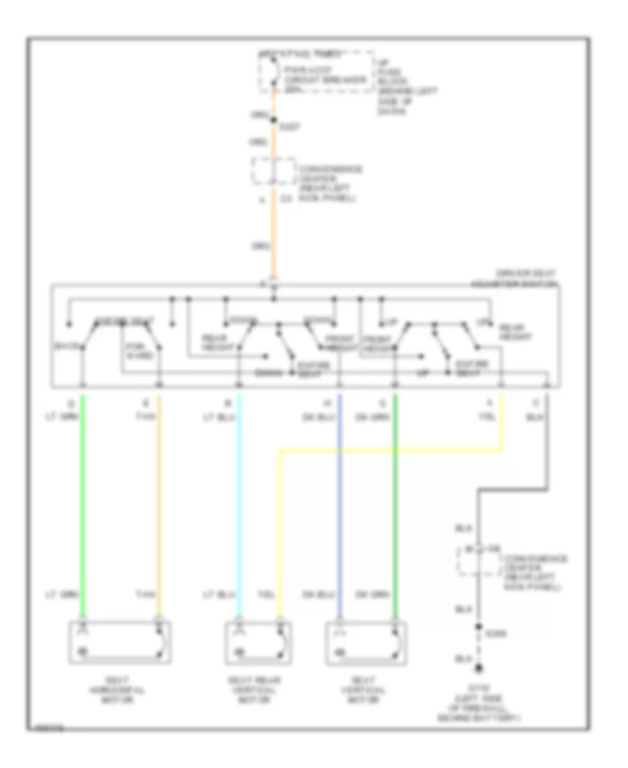
6-Way Power Seat Wiring Diagram for Chevrolet Astro 2002
 https://portal-diagnostov.com/license.html
Automotive Electricians Portal FZCO
Automotive Electricians Portal FZCO
https://portal-diagnostov.com/license.html
https://portal-diagnostov.com/license.html
Automotive Electricians Portal FZCO
Automotive Electricians Portal FZCOList of elements for 6-Way Power Seat Wiring Diagram for Chevrolet Astro 2002:
- Back
- Convenience center (near left kick panel)
- Convenience center (near left kick panel) c3
- Down
- Driver seat adjuster switch
- Entire seat
- For- ward
- Front height
- G110 (left side of firewall, behind battery)
- Hot at all times
- I/p fuse block (behind left side of dash)
- Pwr accy circuit breaker 25a
- Rear height
- S206
- S227
- Seat horizontal motor
- Seat rear vertical motor
- Seat vertical motor
- Tan
POWER WINDOWS
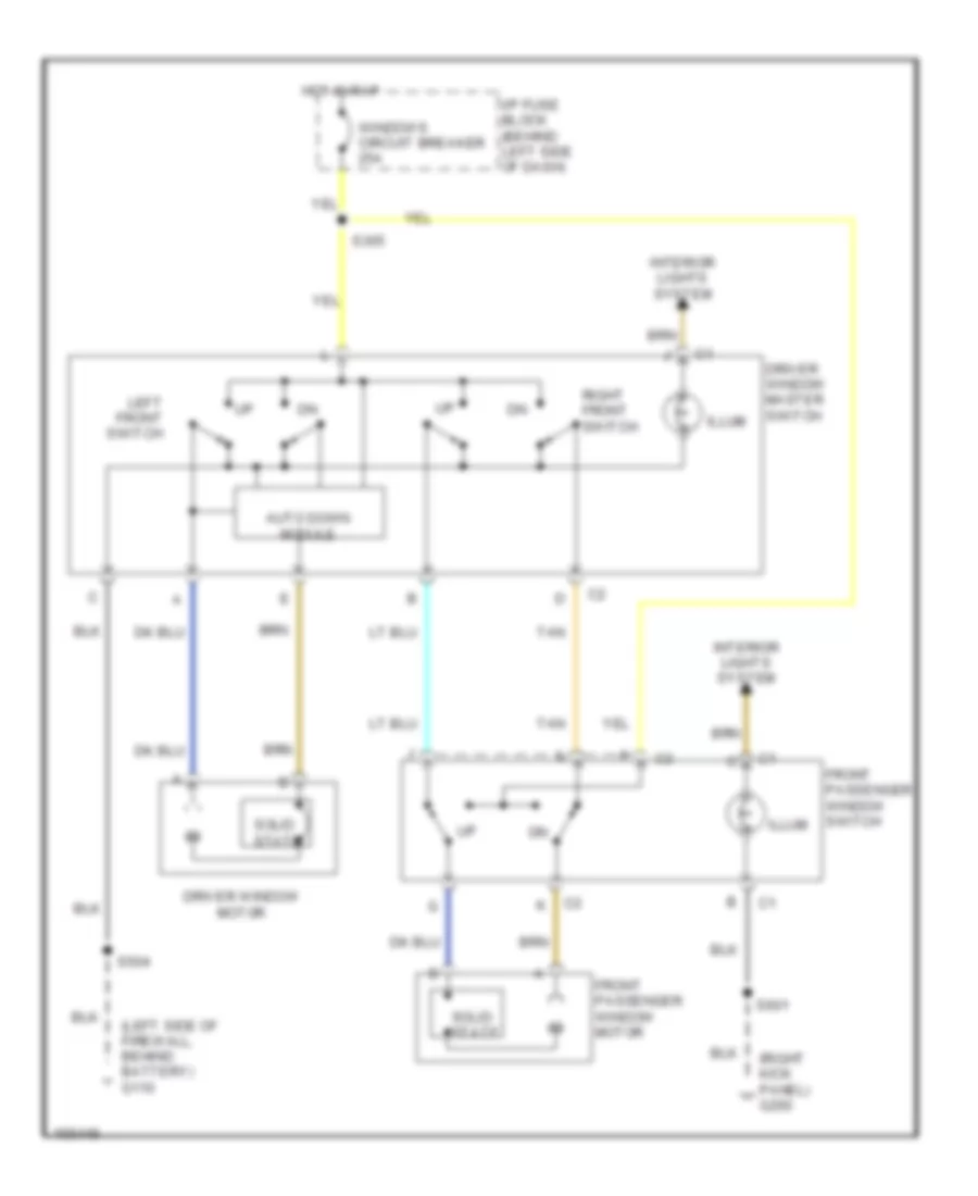
Power Window Wiring Diagram for Chevrolet Astro 2002
 https://portal-diagnostov.com/license.html
Automotive Electricians Portal FZCO
Automotive Electricians Portal FZCO
https://portal-diagnostov.com/license.html
https://portal-diagnostov.com/license.html
Automotive Electricians Portal FZCO
Automotive Electricians Portal FZCOList of elements for Power Window Wiring Diagram for Chevrolet Astro 2002:
- (left side of firewall, behind battery) g110
- (right kick panel) g200
- Auto down module
- Driver window master switch
- Driver window motor
- Front passenger window motor
- Front passenger window switch
- Hot in rap
- I/p fuse block (behind left side of dash)
- Illum
- Interior lights system
- Left front switch
- Right front switch
- S305
- S504
- S601
- Solid state
- Tan
- Windows circuit breaker 25a
RADIO
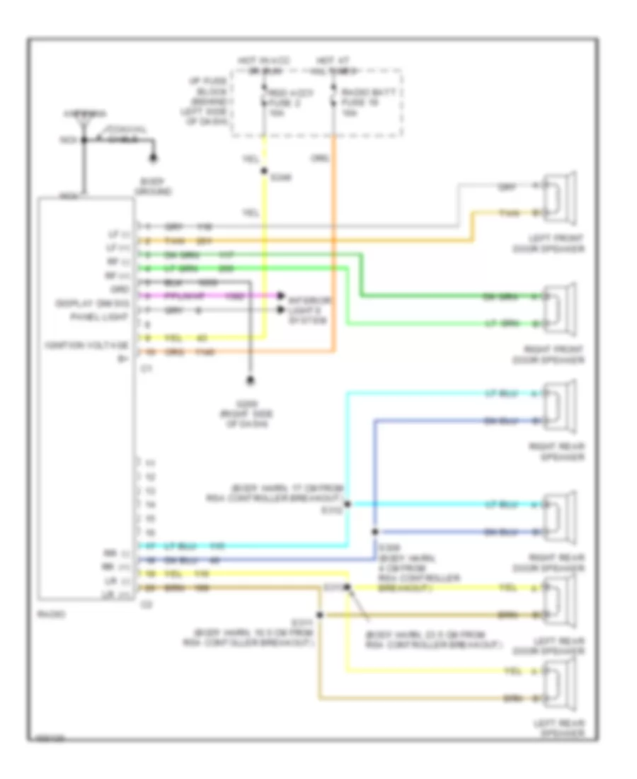
Base Radio for Chevrolet Astro 2002
 https://portal-diagnostov.com/license.html
Automotive Electricians Portal FZCO
Automotive Electricians Portal FZCO
https://portal-diagnostov.com/license.html
https://portal-diagnostov.com/license.html
Automotive Electricians Portal FZCO
Automotive Electricians Portal FZCOList of elements for Base Radio for Chevrolet Astro 2002:
- (body harn, 17 cm from rsa controller breakout)
- (body harn, 23.5 cm from rsa controller breakout)
- Antenna
- Body ground
- Coaxial cable
- Display dim sig
- G200 (right side of dash)
- Grd
- Hot at all times
- Hot in acc or run
- I/p fuse block (behind left side of dash)
- Ignition voltage
- Interior lights system
- Left front door speaker
- Left rear door speaker
- Left rear speaker
- Lf (+)
- Lf (-)
- Lr (+)
- Lr (-)
- Nca
- Panel light
- Radio
- Radio batt fuse 19 10a
- Rdo accy fuse 2 10a
- Rf (+)
- Rf (-)
- Right front door speaker
- Right rear door speaker
- Right rear speaker
- Rr (+)
- Rr (-)
- S246
- S309 (body harn, 4 cm from rsa controller breakout)
- S311 (body harn, 10.5 cm from rsa contoller breakout)
- S312
- S313
- Tan
Premium Sound Radio Wiring Diagram, with Rear Controls for Chevrolet Astro 2002
 https://portal-diagnostov.com/license.html
Automotive Electricians Portal FZCO
Automotive Electricians Portal FZCO
https://portal-diagnostov.com/license.html
https://portal-diagnostov.com/license.html
Automotive Electricians Portal FZCO
Automotive Electricians Portal FZCOList of elements for Premium Sound Radio Wiring Diagram, with Rear Controls for Chevrolet Astro 2002:
- (body harn, 33 cm from the audio amplifier)
- (body harn, 26.5 cm from the audio amplifier)
- (body harn, 4 cm from rsa controller breakout)
- (right door harn, 4 cm from front passenger power window breakout) s603
- 6.5 cm from window motor driver breakout)
- A10
- A11
- A12
- Antenna
- Audio amplifier (left center of vehicle, behind trim panel)
- Audio sig ret
- Aux pwr fuse 7 25a
- B10
- B11
- B12
- Batt in
- Body ground
- Coaxial cable
- Dimmer w
- Display dim sig
- E&c data
- Engine controls system
- Exterior lamps system
- G105 (left rear of engine block)
- G200 (right side of dash)
- G400 (upper half of left "d" pillar)
- Grd
- Ground
- Hot at all times
- Hot in acc or run
- I/p fuse block (behind left side of dash)
- Ign voltage
- Ignition voltage
- Interior lights system
- Left front door speaker
- Left front door tweeter speaker
- Left output
- Left rear speaker
- Left rear sub-woofer speaker
- Lf (+)
- Lf (-)
- Lr (+)
- Lr (-)
- Lr (+)
- Lr (-)
- Lr sw spkr (+)
- Lr sw spkr (-)
- Nca
- Panel light
- Pnk
- Power grd
- R14 in
- Radio
- Radio batt fuse 19 10a
- Radio sig on
- Rdo accy fuse 2 10a
- Rear seat audio (rsa) controller (left side of vehicle, behind "b" pillar)
- Rem rdo cntrl
- Remote cd player
- Rf (+)
- Rf (-)
- Right front door speaker
- Right front door tweeter speaker
- Right output
- Right rear speaker
- Right rear sub-woofer speaker
- Rr (+)
- Rr (-)
- Rr (+)
- Rr (-)
- Rr chnl in (+)
- Rr sw spkr (+)
- Rr sw spkr (-)
- S117
- S246
- S310 (body harn, 4 cm from from rsa controller breakout)
- S314
- S315
- S317
- S318
- S319
- S322
- S328
- S502 (left door harn, 10.5 cm from window motor driver breakout)
- S506 (left door harn, tan
- S602 (right door harn, 10.5 cm from front passenger power window breakout)
- Shield grd
- Tan
- Vss output
Premium Sound Radio Wiring Diagram, without Rear Controls for Chevrolet Astro 2002
 https://portal-diagnostov.com/license.html
Automotive Electricians Portal FZCO
Automotive Electricians Portal FZCO
https://portal-diagnostov.com/license.html
https://portal-diagnostov.com/license.html
Automotive Electricians Portal FZCO
Automotive Electricians Portal FZCOList of elements for Premium Sound Radio Wiring Diagram, without Rear Controls for Chevrolet Astro 2002:
- (body harn, 23.5 cm from rsa controller breakout)
- (left side of vehicle, 4 cm from rsa controller breakout)
- (right door harn, 4 cm from front passenger power window breakout) s603
- 6.5 cm from window motor driver breakout)
- A10
- A11
- A12
- Antenna
- Audio amplifier (left center of vehicle, behind trim panel)
- Audio sig ret
- Aux pwr fuse 7 25a
- B10
- B11
- B12
- Batt in
- Body ground
- Clr
- Coaxial cable
- Dimmer w
- Display dim sig
- E&c data
- Engine controls system
- G200 (right side of dash)
- G400 (upper half of left "d" pillar)
- Grd
- Ground
- Hot at all times
- Hot in acc or run
- I/p fuse block (behind left side of dash)
- Ignition voltage
- Interior lights system
- Left front door speaker
- Left front door tweeter speaker
- Left output
- Left rear speaker
- Left rear sub-woofer speaker
- Lf (+)
- Lf (-)
- Lr (+)
- Lr (-)
- Lr (+)
- Lr (-)
- Lr sw spkr (+)
- Lr sw spkr (-)
- Nca
- Panel light
- Power grd
- R14 in
- Radio
- Radio batt fuse 19 10a
- Rdo accy fuse 2 10a
- Remote play- back device
- Rf (+)
- Rf (-)
- Right front door speaker
- Right front door tweeter speaker
- Right output
- Right rear speaker
- Right rear sub-woofer speaker
- Rr (+)
- Rr (-)
- Rr (+)
- Rr (-)
- Rr sw spkr (+)
- Rr sw spkr (-)
- S246
- S309
- S311 (body harn, 10.5 cm from rsa controller breakout)
- S312 (body harn, 17 cm from rsa controller breakout)
- S313
- S319
- S322
- S502 (left door harn, 10.5 cm from window motor driver breakout)
- S506 (left door harn, tan
- S602 (right door harn, 10.5 cm from front passenger power window breakout)
- Shield grd
- Tan
- Vss output
SHIFT INTERLOCKS
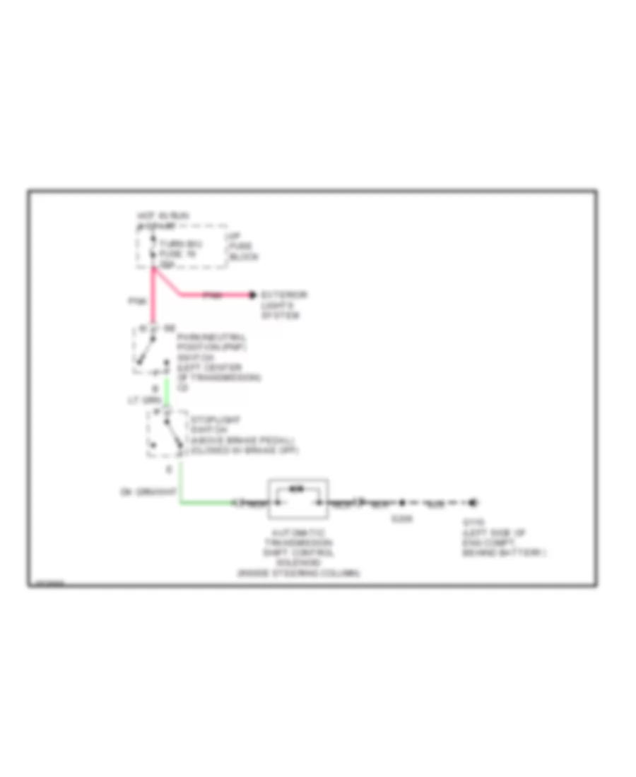
Shift Interlock Wiring Diagram for Chevrolet Astro 2002
 https://portal-diagnostov.com/license.html
Automotive Electricians Portal FZCO
Automotive Electricians Portal FZCO
https://portal-diagnostov.com/license.html
https://portal-diagnostov.com/license.html
Automotive Electricians Portal FZCO
Automotive Electricians Portal FZCOList of elements for Shift Interlock Wiring Diagram for Chevrolet Astro 2002:
- Automatic transmission shift control solenoid (inside steering column)
- Exterior lights system
- G110 (left side of eng compt, behind battery)
- Hot in run & start
- I/p fuse block
- Nca
- Park/neutral position (pnp) switch (left center of transmission) c2
- Pnk
- S206
- Stoplight switch (above brake pedal) (closed w/ brake off)
- Turn b/u fuse 16 20a
STARTING/CHARGING
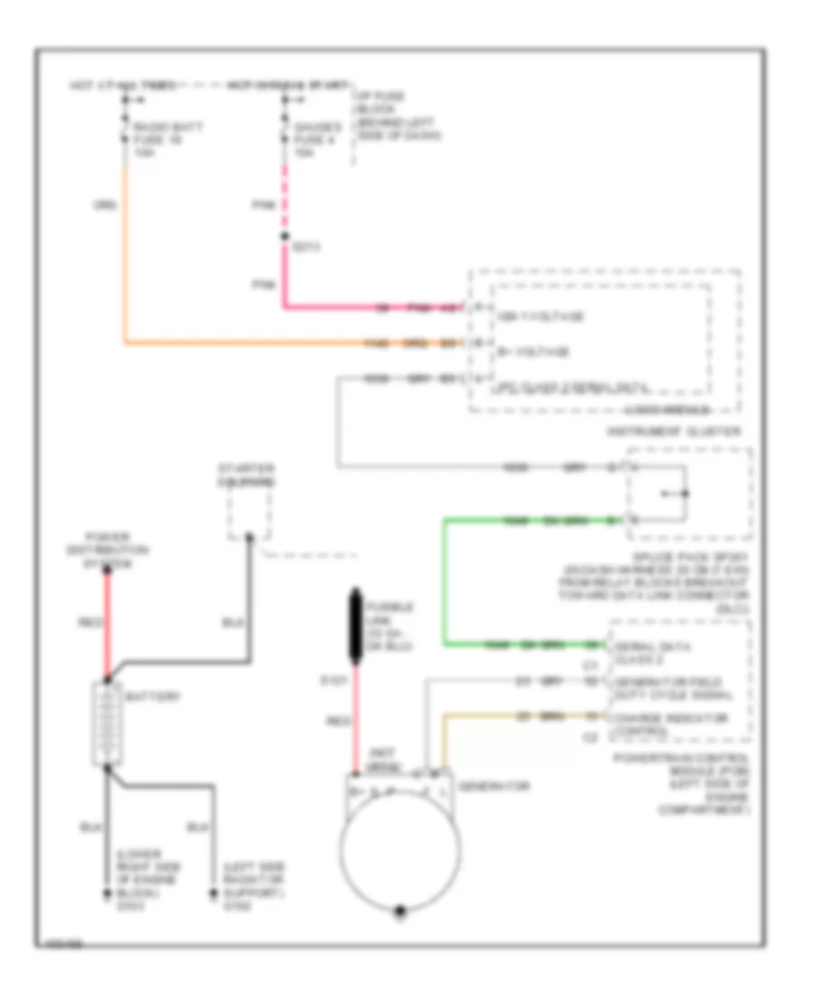
Charging Wiring Diagram for Chevrolet Astro 2002
 https://portal-diagnostov.com/license.html
Automotive Electricians Portal FZCO
Automotive Electricians Portal FZCO
https://portal-diagnostov.com/license.html
https://portal-diagnostov.com/license.html
Automotive Electricians Portal FZCO
Automotive Electricians Portal FZCOList of elements for Charging Wiring Diagram for Chevrolet Astro 2002:
- (left side radiator support) g102
- (lower right side of engine block) g103
- (not used)
- B+ voltage
- Battery
- Charge indicator control
- Gauges fuse 4 10a
- Generator
- Generator field duty cycle signal
- Hot at all times
- Hot in run & start
- I/p fuse block (behind left side of dash)
- Ign 1 voltage
- Instrument cluster
- Ipc class 2 serial data
- Logic module
- Pnk
- Power distribution system
- Powertrain control module (pcm) (left side of engine compartment)
- Radio batt fuse 19 10a
- Red
- S121
- S213
- Serial data class 2
- Splice pack sp261 (in dash harness 20 cm (7.9 in) from relay blocks breakout toward data link connector (dlc))
- Starter solenoid
Starting Wiring Diagram for Chevrolet Astro 2002
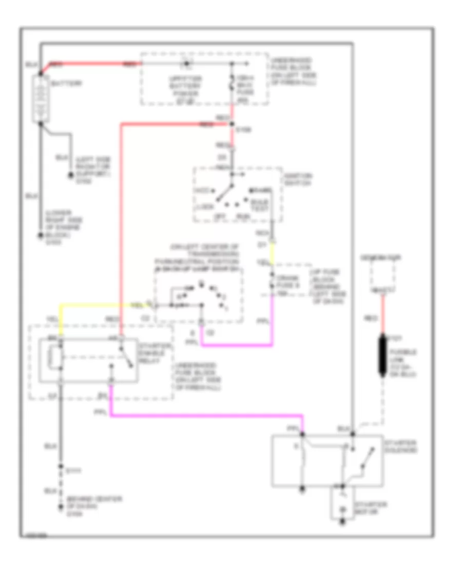 https://portal-diagnostov.com/license.html
Automotive Electricians Portal FZCO
Automotive Electricians Portal FZCO
https://portal-diagnostov.com/license.html
https://portal-diagnostov.com/license.html
Automotive Electricians Portal FZCO
Automotive Electricians Portal FZCOList of elements for Starting Wiring Diagram for Chevrolet Astro 2002:
- (behind center of dash) g104
- (lower right side of engine block) g103
- (on left center of transmission) park/neutral position & back-up lamp switch
- Acc
- Batt
- Battery
- Bulb test
- Crank fuse 8 10a
- Generator
- I/p fuse block (behind left side of dash)
- Ign-a maxi fuse 40a
- Ignition switch
- Lock
- Nca
- Off
- Red
- Run
- S108
- S111
- S121
- Start
- Starter enable relay
- Starter motor
- Starter solenoid
- Underhood fuse block (on left side of firewall)
- Upfitter battery power stud
SUPPLEMENTAL RESTRAINTS
Supplemental Restraint Wiring Diagram for Chevrolet Astro 2002
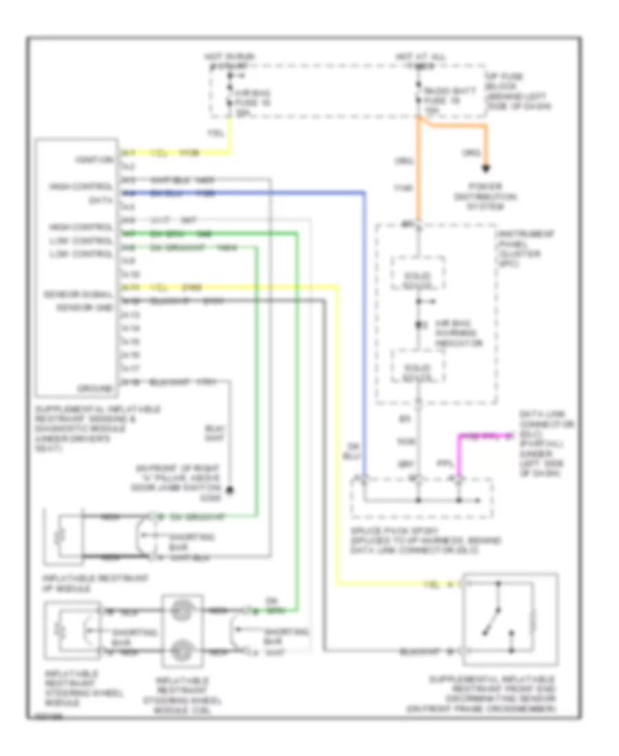 https://portal-diagnostov.com/license.html
Automotive Electricians Portal FZCO
Automotive Electricians Portal FZCO
https://portal-diagnostov.com/license.html
https://portal-diagnostov.com/license.html
Automotive Electricians Portal FZCO
Automotive Electricians Portal FZCOList of elements for Supplemental Restraint Wiring Diagram for Chevrolet Astro 2002:
- (in front of right "a" pillar, above door jamb switch) g300
- (partial) (under left side of dash)
- A10
- A11
- A12
- A13
- A14
- A15
- A16
- A17
- A18
- Air bag fuse 10 10a
- Air bag warning indicator
- Data
- Ground
- High control
- Hot at all times
- Hot in run & start
- I/p fuse block (behind left side of dash)
- Ignition
- Inflatable restraint i/p module
- Inflatable restraint steering wheel module
- Inflatable restraint steering wheel module coil
- Instrument panel cluster (ipc)
- Low control
- Nca
- Power distribution system
- Radio batt fuse 19 10a
- Sensor gnd
- Sensor signal
- Shorting bar
- Solid state
- Splice pack sp261 (spliced to i/p harness, behind data link connector (dlc)
TRANSMISSION
4.3L
4.3L VIN W, A/T Wiring Diagram for Chevrolet Astro 2002
 https://portal-diagnostov.com/license.html
Automotive Electricians Portal FZCO
Automotive Electricians Portal FZCO
https://portal-diagnostov.com/license.html
https://portal-diagnostov.com/license.html
Automotive Electricians Portal FZCO
Automotive Electricians Portal FZCOList of elements for 4.3L VIN W, A/T Wiring Diagram for Chevrolet Astro 2002:
- (engine harn, near breakout to underhood fuse block) s112
- (in the thermostat housing)
- +5v
- 1-2 shift solenoid
- 1-2 ss
- 2-3 shift solenoid
- 2-3 ss
- 3-2 shift solenoid
- 3-2 ss
- A/t fluid pressure manual valve position switch
- A12
- Anti-lock brakes system
- Automatic transmission (4l60-e)
- Body control module (above radio)
- Brake fuse 18 10a
- Brk sw
- Cls 2 data
- Convenience center
- Cruise control system
- D3, d2
- D4, d2
- Data link connector (under left side of dash)
- Ecm b fuse 20a
- Ecm i fuse 20a
- Ect sig
- Electronic brake control module
- Engine coolant temperature sensor (left side of left cyl head)
- Fluid temp sensor
- Fuel pump relay
- G105
- G105 (in the thermostat housing)
- G106 (left rear of engine block)
- Gnd
- Hot at all times
- Hot in run
- Hot in run & start
- I/p fuse block (behind left side of dash)
- Ign
- Ignition
- Ignition coil, ignition control module, fuel injectors
- Instrument panel cluster (ipc)
- Lo ref
- Malfunction indicator lamp
- Mil ctrl
- Park/neutral position switch (left center of transmission)
- Pc sol hi
- Pc sol lo
- Pnk
- Powertrain control module (left side of firewall)
- Press ctrl solenoid
- Prnd a
- Prnd b
- Prnd c
- Prnd p
- Radio
- Radio fuse 19 10a
- Range b
- Range c
- Red
- Red a
- Red b
- Rev, lo
- S109
- S115
- S116
- S117
- S127
- S155
- Sens gnd
- Splice pack sp261 (left side of dash)
- Stoplamp switch (above brake pedal)
- Tan
- Tcc pwm
- Tcc pwm solenoid
- Tcc sol
- Tcc solenoid
- Tft sens sig
- Throttle position sensor (left side of throttle body)
- Tp sig
- Trans fuse 20 10a
- Trans rng a
- Underhood fuse block (left side of firewall)
- Vehicle speed sensor (rear of transmission)
- Vss hi
- Vss lo
4.3L VIN W, Transfer Case Wiring Diagram for Chevrolet Astro 2002
 https://portal-diagnostov.com/license.html
Automotive Electricians Portal FZCO
Automotive Electricians Portal FZCO
https://portal-diagnostov.com/license.html
https://portal-diagnostov.com/license.html
Automotive Electricians Portal FZCO
Automotive Electricians Portal FZCOList of elements for 4.3L VIN W, Transfer Case Wiring Diagram for Chevrolet Astro 2002:
- Atc
- Battery
- Brake
- C8 convenience center (left of i/p fuse block, by left kick panel)
- Convenience center (left of i/p fuse block, by left kick panel)
- Data link connector (dlc) (partial) (under left side of dash)
- E10
- E11
- E12
- E13
- E14
- E15
- E16
- F10
- F11
- F12
- F13
- F14
- F15
- F16
- Front propshaft speed sensor (near center of transfer case)
- Fuse 18 10a
- Fuse 20a
- G110 (left side of engine compt, behind battery)
- Ground
- Hot at all times
- Hot in run
- I/c logic
- I/p fuse block (behind left side of dash)
- Ignition
- Instrument panel cluster (ipc)
- Radio batt fuse 19 10a
- Rear propshaft speed sensor (near center of transfer case)
- Red
- Rr vss
- S206
- S243
- Serial data
- Service awd ind
- Sound system (radio)
- Sp261 (behind data link connector)
- Stoplamp switch, electronic brake control module)
- Tc motor
- Transfer case encoder motor (inside transfer case)
- Transfer case shift control module (behind left kick panel)
- Underhood fuse block (on left side of firewall)
- Voltage regulator
- Vss
TRUNK, TAILGATE, FUEL DOOR
Rear Glass Release Wiring Diagram for Chevrolet Astro 2002
 https://portal-diagnostov.com/license.html
Automotive Electricians Portal FZCO
Automotive Electricians Portal FZCO
https://portal-diagnostov.com/license.html
https://portal-diagnostov.com/license.html
Automotive Electricians Portal FZCO
Automotive Electricians Portal FZCOList of elements for Rear Glass Release Wiring Diagram for Chevrolet Astro 2002:
- (i/p harn, 10cm from radio con- nectors breakout)
- (i/p harn, 18cm from c205 conn in right kick panel)
- Cig ltr fuse 13 20a
- Door lock relay (right kick panel)
- Door locks system
- G200 (right kick panel)
- G403 (upper half of left "d" pillar)
- Hot at all times
- I/p fuse block (left side of dash)
- Liftglass lock/unlock relay (right rear quarter panel)
- Liftglass lock/unlock release switch
- Liftglass release actuator
- Lock
- Nca
- Pwr accy circuit breaker 25a
- Rear door lock motor
- Release switch
- S223
- S227
- S228
- S229
- S230
- S334 (liftgate harn, 49.5 cm from breakout to liftgate lock/ unlock relay)
- S335 (liftgate harn, 56 cm from breakout to liftgate lock/ unlock relay)
- S407
- Tan
- Unlock
WARNING SYSTEMS
Warning System Wiring Diagrams for Chevrolet Astro 2002
 https://portal-diagnostov.com/license.html
Automotive Electricians Portal FZCO
Automotive Electricians Portal FZCO
https://portal-diagnostov.com/license.html
https://portal-diagnostov.com/license.html
Automotive Electricians Portal FZCO
Automotive Electricians Portal FZCOList of elements for Warning System Wiring Diagrams for Chevrolet Astro 2002:
- (dash harn, near breakout to i/p fuse block)
- (i/p harn, behind
- (i/p harn, behind instrument cluster)
- (left front radiator support) g101
- (left side of firewall behind battery) g110
- (upper half of left "d" pillar g400
- A12
- B10
- B11
- Body control module (above radio)
- Brake pressure differential switch (on brake pressure modulator valve assy)
- C201
- Driver door jamb switch
- Drvr dr jamb sig
- Electronic brake control module (left side of frame, left of transmission)
- Exterior lights
- Head
- Headlamp & panel dimmer switch
- Hot at all times
- I/p fuse block
- Ignition key alarm switch
- Ignition switch
- Instrument cluster)
- Instrument panel cluster
- Instrument panel cluster (ipc)
- Key in inp
- Multi- function turn signal lever
- Nca
- Nca b
- Off
- Park
- Park brake indicator switch (base of park brake lever)
- Park brake inp
- Park/head on inp
- Pk lps fuse 9 20a
- S110
- S130
- S206
- S211
- S212 (i/p harn, behind instrument cluster)
- S217
- S251 (i/p harn, at base of steering column)
- S256
- S319
- Seat belt buckle switch (on driver's seat belt buckle)
- Seat belt inp
- Serial data
- Splice pack 261 (i/p harn, 20 cm from relay blocks breakout)
- Start
- Switch input
- Turn input
- Vehicle speed out
- Vss
WIPER/WASHER
Front Wiper/Washer Wiring Diagram for Chevrolet Astro 2002
 https://portal-diagnostov.com/license.html
Automotive Electricians Portal FZCO
Automotive Electricians Portal FZCO
https://portal-diagnostov.com/license.html
https://portal-diagnostov.com/license.html
Automotive Electricians Portal FZCO
Automotive Electricians Portal FZCOList of elements for Front Wiper/Washer Wiring Diagram for Chevrolet Astro 2002:
- 150k
- 240k
- 30k
- 430k
- 68k
- C201
- Delay
- Delay/ low
- G100 (right front radiator support)
- G110 (left side of firewall, above battery)
- High
- Hot in run
- I/p fuse block (behind left side of dash)
- Inst
- Inst wipe
- Mist
- Mist off
- Multifunction turn signal lever
- Nca
- Off
- Pnk
- S100
- S206
- S324
- Solid state
- Wash
- Washer switch
- Windshield washer fluid pump (in windshield washer reservoir)
- Windshield wiper motor & module (on center of firewall, next to cruise control module)
- Wipe
- Wiper fuse 25a
- Wiper switch
Rear Wiper/Washer Wiring Diagram for Chevrolet Astro 2002
 https://portal-diagnostov.com/license.html
Automotive Electricians Portal FZCO
Automotive Electricians Portal FZCO
https://portal-diagnostov.com/license.html
https://portal-diagnostov.com/license.html
Automotive Electricians Portal FZCO
Automotive Electricians Portal FZCOList of elements for Rear Wiper/Washer Wiring Diagram for Chevrolet Astro 2002:
- 12v ref
- Delay
- Delay/on
- G100 (right front radiator support)
- G403 (upper half of right "d" pillar)
- Ground
- Hot in run
- I/p fuse block (behind left side of dash)
- Interior lights system
- Off
- Park sw
- Park switch
- Rear window washer motor (in left side of liftgate)
- Rear window wiper motor (in center of liftgate)
- Rear window wiper/ washer switch
- Rear window wiper/washer module (in left side of liftgate)
- Rr wiper fuse 23 20a
- S100
- S241 (in dash harness 69.5 cm (27.4 in) from right kick panel)
- S407
- Wash

 Čeština
 Dansk
Dansk Deutsch
 Ελληνικά
 English
 English
 Español
 Suomi
Suomi Français
 Français
 עברית
עברית Hrvatski
 Magyar
 Italiano
 日本語
日本語 한국어
한국어 Nederlands
 Polski
 Português
 Português
 Română
 Русский
 Slovenčina
 Slovenščina
 Svenska
 中文 (中国)
