AIR CONDITIONING
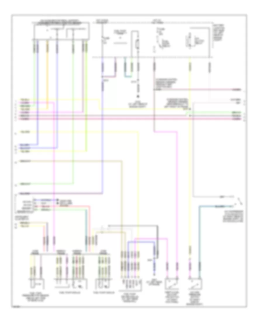
Automatic A/C Wiring Diagram (1 of 3) for Ford Cab & Chassis F350 Super Duty 2008
 https://portal-diagnostov.com/license.html
Automotive Electricians Portal FZCO
Automotive Electricians Portal FZCO
https://portal-diagnostov.com/license.html
https://portal-diagnostov.com/license.html
Automotive Electricians Portal FZCO
Automotive Electricians Portal FZCO
List of elements for Automatic A/C Wiring Diagram (1 of 3) for Ford Cab & Chassis F350 Super Duty 2008:
- (at top left of hvac module) electric heater
- (crew cab & regular cab: in left "a" pillar) (super cab: behind left side of dash)
- (in extension assembly-a/c blower motor feed harness, near top of hvac housing) s250
- (in extension assembly-a/c blower motor feed harness, near top of hvac housing) s251
- 150a
- Ambient
- Battery
- Battery junction box (bjb) (at left rear of engine compt)
- Blower command
- Blower motor relay
- C2280a
- C2280b
- C2280e
- C228a
- C2357b
- C2463a
- C2463b
- C2463c
- Cable pro
- Cbp37
- Ch122
- Ch123
- Ch207
- Ch208
- Ch211
- Ch213
- Ch228
- Ch229
- Ch237
- Ch239
- Chs29
- Chs30
- Computer data lines system
- Driver temperature blend door actuator (at bottom of hvac assembly)
- Drv htd seat sw
- Drv sun load
- Drv temp a+
- Drv temp b+
- Drv temp feedback
- Front blower rly
- Fuse 10a
- Fuse 40a
- Fuse 5a
- G300
- Gd133
- Gnd
- Heated mirror relay
- Hot at all times
- Hot in run or acc
- Hot in run or start
- Hscan+
- Hscan-
- Hvac-eatc
- Incar temp sn
- Lh111
- Mode actr a+
- Mode actr b+
- Mode actr feedback
- Mscan+
- Mscan-
- Nca
- Panel/defrost mode actuator (at left side of hvac assembly)
- Pass htd seat sw
- Pass sun load
- Pass temp a+
- Pass temp b+
- Pass temp feedback
- Passenger temperature blend door actuator (at top middle of hvac assembly)
- Rear def htd mirror
- Recirc door a+
- Recirc door b+
- Recirculation door actuator (at right side of hvac case)
- Red
- Rh111
- S104
- S143
- S144
- S145
- S206
- S224
- Sbp15
- Smart junction box (on passenger side kick panel)
- Steering wheel sw in
- Vbat
- Vdb06
- Vdb07
- Vh101
- Vh407
- Vh414
- Vh416
- Vh417
- Vh436
- Vh440
- Vh441
- Vh444
- Vign
- Vref actr
- Vref rtn
- W/ electric heater
- W/o electric heater
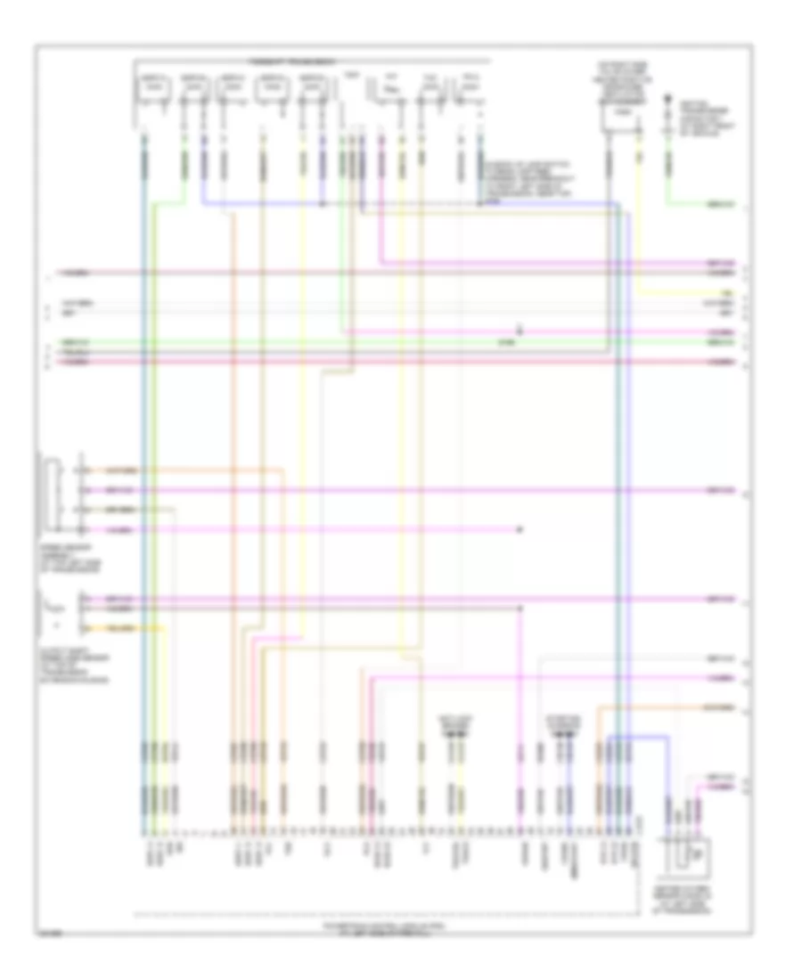
Automatic A/C Wiring Diagram (2 of 3) for Ford Cab & Chassis F350 Super Duty 2008
 https://portal-diagnostov.com/license.html
Automotive Electricians Portal FZCO
Automotive Electricians Portal FZCO
https://portal-diagnostov.com/license.html
https://portal-diagnostov.com/license.html
Automotive Electricians Portal FZCO
Automotive Electricians Portal FZCOList of elements for Automatic A/C Wiring Diagram (2 of 3) for Ford Cab & Chassis F350 Super Duty 2008:
- (at right side of hvac assembly) blower motor control module
- (behind center of dash) autolamp/sunload sensor
- (below driver seat) driver side front heated seat relay
- (below passenger seat) passenger side front heated seat relay
- (in extension
- Assembly-a/c blower motor feed harness, at right side of hvac case)
- Blower motor
- C218a
- C218b
- Ch218
- Ch402
- Clock spring (in steering column)
- Fan down
- Fan up
- G203 (behind center of dash, behind audio control module)
- G300 (crew cab & regular cab: in left "a" pillar) (super cab: behind left side of dash)
- Gd115
- Headlights system
- In vehicle temperature sensor (behind left side of dash)
- Outside air temperature sensor (at right front of engine compt)
- S210 (in main harness, near breakout behind audio control module)
- S225
- S257
- Solid state control
- Steering wheel/speed control switch
- Vh101
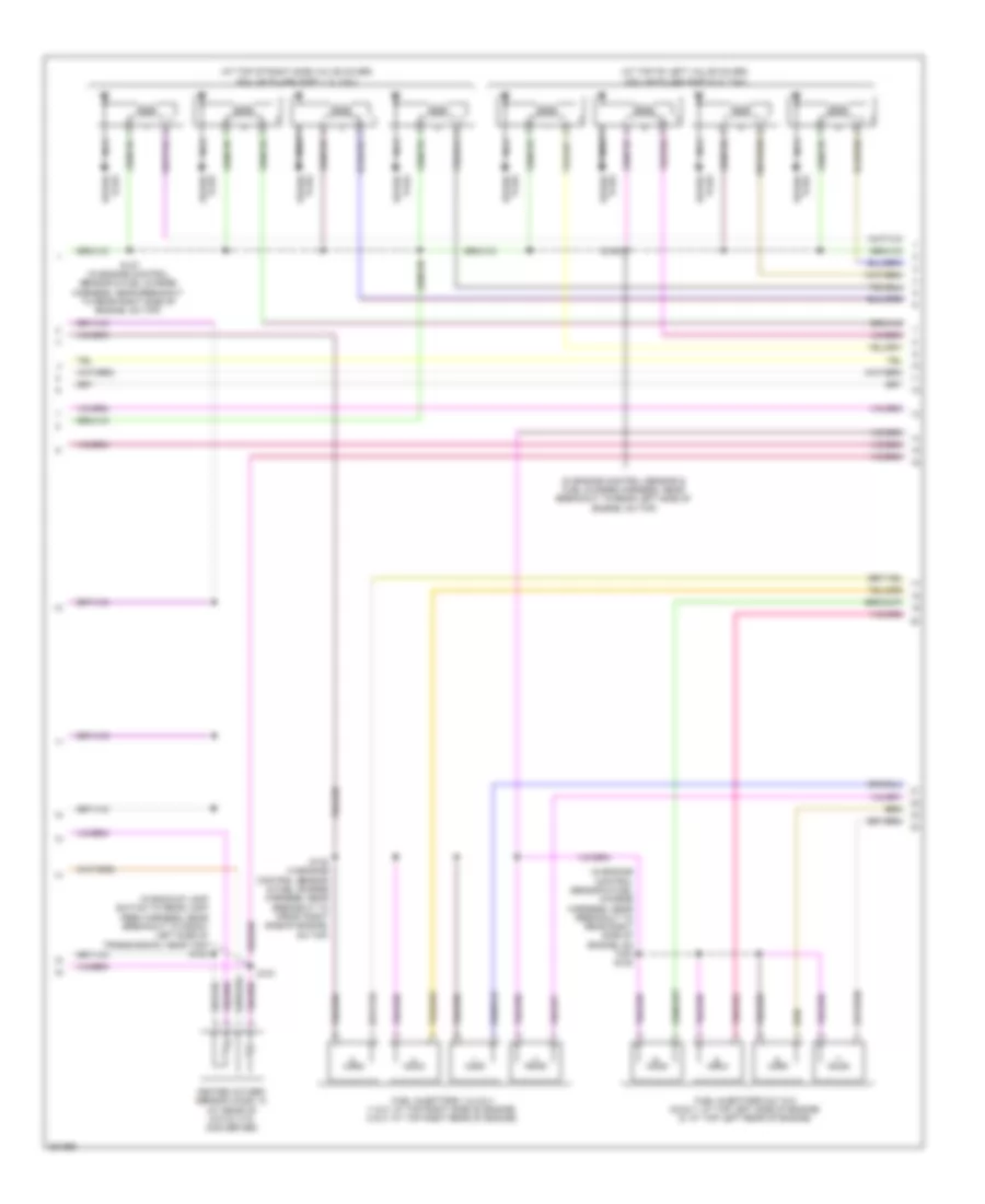
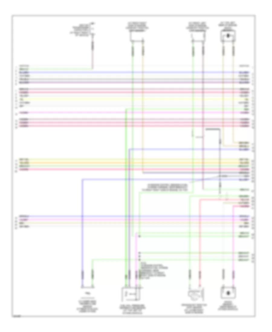
Automatic A/C Wiring Diagram (3 of 3) for Ford Cab & Chassis F350 Super Duty 2008
 https://portal-diagnostov.com/license.html
Automotive Electricians Portal FZCO
Automotive Electricians Portal FZCO
https://portal-diagnostov.com/license.html
https://portal-diagnostov.com/license.html
Automotive Electricians Portal FZCO
Automotive Electricians Portal FZCOList of elements for Automatic A/C Wiring Diagram (3 of 3) for Ford Cab & Chassis F350 Super Duty 2008:
- (at front of engine) (diesel) engine coolant temperature (ect) sensor
- (diesel)
- (diesel) (gas)
- (gas)
- (in engine control sensor & fuel charge harness, near breakout to front right side of engine, on top) s133
- (in engine control sensor harness, near breakout to front center of engine compt)
- (in engine control sensor harness, near breakout to front right side of engine, on top) s1013
- A/c clutch diode
- A/c clutch relay
- A/c clutch solenoid
- A/c cycling switch
- A/c cycling switch (gas)
- A/c high pressure switch (at right side of engine compt)
- Accr
- Accs
- Acpsw
- Audio/climate control switch
- Battery junction box (bjb) (at left rear of engine compt)
- Brake pressure switch (at bottom of master cylinder)
- C1232b
- C1232e
- C175b
- C175e
- Ce237
- Cec11
- Ch302
- Ch421
- Ch425
- Cht
- Control
- Cylinder head temperature sensor (6.8l: on right cylinder head) (5.4l: at rear of block, under intake)
- Diesel
- Dual pressure switch (diesel) (at right front of engine)
- Ect
- Electric fan clutch (at front of engine)
- Engine controls system
- Fuse 10a
- Fuse 20a
- Fuse 50 (gas) 30a fuse 39 (diesel) 50a
- G103 (at right rear of engine compt)
- G108 (at left rear of engine compt)
- Gas
- Gd119
- Gnd
- Hot at all times
- Interior lights system
- Kapwr
- Media
- Mpr (pcm-rc)
- Nca control
- Nca gnd
- Nca sig
- Nca vbpwr
- Nca vpwr
- Near breakout to left front of frame)
- Pcm power relay
- Powertrain control module (pcm) (at left side of firewall)
- Re405
- S1008 (in engine control sensor harness, near breakout to right rear of engine compt)
- S1009 (in engine control sensor harness, near breakout to front right side of engine, on top)
- S1010 (in engine control sensor harness, near breakout to front right side of engine, on top)
- S114
- S115
- S117 (diesel)
- S120
- S128
- S154 (gas)
- S158 (gas)
- Sbb36
- Seek +
- Seek -
- Sig
- Sig rtn
- Sound systems
- Temp +
- Temp -
- Vbpwr
- Ve712
- Ve716
- Vec03
- Vec10
- Vol +
- Vol -
Manual A/C Wiring Diagram (1 of 2) for Ford Cab & Chassis F350 Super Duty 2008
 https://portal-diagnostov.com/license.html
Automotive Electricians Portal FZCO
Automotive Electricians Portal FZCO
https://portal-diagnostov.com/license.html
https://portal-diagnostov.com/license.html
Automotive Electricians Portal FZCO
Automotive Electricians Portal FZCOList of elements for Manual A/C Wiring Diagram (1 of 2) for Ford Cab & Chassis F350 Super Duty 2008:
- (at top left of hvac module) electric heater
- (behind center of dash, behind audio control module) g203
- (in extension assembly-a/c blower motor feed harness, at right side of hvac case) s256
- (in extension assembly-a/c blower motor feed harness, near top of hvac housing) s251
- 150a
- Battery
- Battery junction box (bjb) (at left rear of engine compt)
- Blower motor
- Blower motor relay
- C2280a
- C2280b
- C2280e
- C2357a
- C2357b
- C2463a
- C2463b
- C2463c
- Cable pro
- Cbp37
- Ch122
- Ch123
- Ch202
- Ch203
- Ch207
- Ch208
- Ch233
- Ch234
- Ch428
- Ch429
- Ch430
- Chs29
- Chs30
- Computer data lines system
- Driver side front heated seat relay (below driver seat)
- Drv htd seat sw
- Drv temp a+
- Drv temp b+
- Drv temp feedback
- Front blower motor resistor assembly (at right side of hvac assembly)
- Front blower rly
- Fuse 10a
- Fuse 40a
- Fuse 5a
- G203 (behind center of dash, behind audio control module)
- G300 (crew cab & regular cab: in left "a" pillar) (super cab: behind left side of dash)
- Gd115
- Gd133
- Gnd
- Heated mirror relay
- Hot at all times
- Hot in run or acc
- Hot in run or start
- Hscan+
- Hscan-
- Hvac-emtc
- Lh111
- Med hi
- Med lo
- Mode actr a+
- Mode actr b-
- Mscan+
- Mscan-
- Nca
- Panel/defrost feedback
- Panel/defrost mode actuator (at left side of hvac assembly)
- Pass htd seat sw
- Passenger side front heated seat relay (below passenger seat)
- Rear def htd mirror
- Recirc door a+
- Recirc door b+
- Red
- Rh111
- S104
- S143
- S144
- S145
- S206
- S224
- S225
- S250 (in extension assembly-a/c blower motor feed harness, near top of hvac housing)
- Sbp15
- Smart junction box (on passenger side kick panel)
- Temperature blend door actuator (behind right side of dash)
- Vbat
- Vdb06
- Vdb07
- Vh437
- Vh439
- Vign
- Vref actr
- Vref return
- W/ electric heater
- W/o electric heater
Manual A/C Wiring Diagram (2 of 2) for Ford Cab & Chassis F350 Super Duty 2008
 https://portal-diagnostov.com/license.html
Automotive Electricians Portal FZCO
Automotive Electricians Portal FZCO
https://portal-diagnostov.com/license.html
https://portal-diagnostov.com/license.html
Automotive Electricians Portal FZCO
Automotive Electricians Portal FZCOList of elements for Manual A/C Wiring Diagram (2 of 2) for Ford Cab & Chassis F350 Super Duty 2008:
- (at front of engine) (diesel) engine coolant temperature (ect) sensor
- (diesel)
- (diesel) (gas)
- (gas)
- (in engine control sensor & fuel charge harness, near breakout to front right side of engine, on top) s133
- (in engine control sensor harness, near breakout to front center of engine compt)
- (in engine control sensor harness, near breakout to front right side of engine, on top) s1013
- A/c clutch diode
- A/c clutch relay
- A/c clutch solenoid
- A/c cycling switch
- A/c cycling switch (gas)
- A/c high pressure switch (at right side of engine compt)
- Accr
- Accs
- Acpsw
- Battery junction box (bjb) (at left rear of engine compt)
- Brake pressure switch (at bottom of master cylinder)
- C1232b
- C1232e
- C175b
- C175e
- Ce237
- Cec11
- Ch302
- Ch421
- Ch425
- Cht
- Control
- Cylinder head temperature sensor (6.8l: on right cylinder head) (5.4l: at rear of block, under intake)
- Diesel
- Dual pressure switch (diesel) (at right front of engine)
- Ect
- Electric fan clutch (at front of engine)
- Engine controls system
- Fuse 10a
- Fuse 20a
- Fuse 50 (gas) 30a fuse 39 (diesel) 50a
- G103 (at right rear of engine compt)
- G108 (at left rear of engine compt)
- Gas
- Gd119
- Gnd
- Hot at all times
- Kapwr
- Mpr (pcm-rc)
- Nca control
- Nca gnd
- Nca sig
- Nca vbpwr
- Nca vpwr
- Near breakout to left front of frame)
- Pcm power relay
- Powertrain control module (pcm) (at left side of firewall)
- Re405
- Recirculation door actuator (at right side of hvac case)
- S1008 (in engine control sensor harness, near breakout to right rear of engine compt)
- S114
- S115
- S120
- S128
- S154 s117 (diesel)
- S158 (gas)
- Sbb36
- Sig
- Sig rtn
- Vbpwr
- Ve712
- Ve716
- Vec03
- Vec10
ANTI-LOCK BRAKES
Anti-lock Brakes Wiring Diagram for Ford Cab & Chassis F350 Super Duty 2008
 https://portal-diagnostov.com/license.html
Automotive Electricians Portal FZCO
Automotive Electricians Portal FZCO
https://portal-diagnostov.com/license.html
https://portal-diagnostov.com/license.html
Automotive Electricians Portal FZCO
Automotive Electricians Portal FZCOList of elements for Anti-lock Brakes Wiring Diagram for Ford Cab & Chassis F350 Super Duty 2008:
- (at left front of frame) g135
- (in engine control sensor harness, near breakout to left front of frame) s106
- (or le111)
- Abs control module (diesel: at left side of engine compt) (except diesel: at left rear of engine compt)
- Battery junction box (bjb) (at left rear of engine compt)
- Bpp
- Bps
- Brake pedal position switch (behind left side of dash, above brake pedal)
- Brake pressure switch (at bottom of master cylinder)
- C1232b
- C1232e
- C175b
- C175e
- C175t
- C2280b
- Cbb77
- Cca10
- Cca15
- Ccb08
- Cec11
- Ces09
- Computer data lines system
- Cooling fans & transmissions systems
- Diesel
- Diff sen+
- Diff sen-
- Exterior lights system
- Fl gnd
- Fr gnd
- Fuse 10a
- Fuse 40a
- Fuse 5a
- G135 (at left front of frame)
- Gas
- Gd163
- Gnd
- Hot at all times
- Hot in run or start
- Hs can +
- Hs can -
- Ign
- Interior lights system
- Kl30 p
- Kl30 v
- Left front wheel speed sensor (at left front wheel assembly)
- Lf whl spd+
- Powertrain control module (pcm) (at left side of firewall)
- Rca17
- Rca19
- Rca21
- Rear axle speed sensor (on differential)
- Red
- Rf whl spd+
- Right front wheel speed sensor (at right front wheel assembly)
- S1009 (diesel) s196 (gas) (diesel: in engine control sensor harness, near breakout to front right side of engine, on top) (gas: in backup lamp switch to rear lamp feed harness, near breakout to front left side of transmission, near top)
- S130 (in engine control sensor harness, near breakout to master cylinder)
- S211 (in main harness, near breakout behind audio control module)
- S227
- S404 (in tail lamps harness, in breakout to left rear of frame)
- S405 (in tail lamps harness, in breakout to left rear of frame)
- Sbb06
- Sbb09
- Smart junction box (on passenger side kick panel)
- Tracs
- Tracsil
- Traction control switch
- Vbpwrt (or vbpwr)
- Vca03
- Vca05
- Vca07
- Vdb04
- Vdb05
- Ve822
- Vss
- Wiper/ washer system
ANTI-THEFT
Forced Entry Wiring Diagram (1 of 2) for Ford Cab & Chassis F350 Super Duty 2008
 https://portal-diagnostov.com/license.html
Automotive Electricians Portal FZCO
Automotive Electricians Portal FZCO
https://portal-diagnostov.com/license.html
https://portal-diagnostov.com/license.html
Automotive Electricians Portal FZCO
Automotive Electricians Portal FZCOList of elements for Forced Entry Wiring Diagram (1 of 2) for Ford Cab & Chassis F350 Super Duty 2008:
- (crew cab: in body main harness, near breakout to right "a" pillar) (regular cab: in body main harness, near breakout to right "b" pillar) (super cab: in body main harness, near breakout under passenger seat)
- (super cab: in body main harness, near breakout under passenger seat) (except super cab: in body main harness, near breakout to right "b" pillar)
- All lock relay
- Antenna
- C2280c
- C2280d
- Control
- Driver side door lock switch
- Driver unlock relay
- Fuse 15a
- Fuse 20a
- G302 (in right "a" pillar)
- Hot at all times
- Hot w/ accessory delay relay energized
- Hsd
- Lock
- Logic
- Passenger side door lock switch
- Rke receiver internal antenna
- S301
- S305
- S306
- S308
- S501
- S639
- Sense
- Smart junction box (sjb) (on passenger side kick panel)
- Un lock
Forced Entry Wiring Diagram (2 of 2) for Ford Cab & Chassis F350 Super Duty 2008
 https://portal-diagnostov.com/license.html
Automotive Electricians Portal FZCO
Automotive Electricians Portal FZCO
https://portal-diagnostov.com/license.html
https://portal-diagnostov.com/license.html
Automotive Electricians Portal FZCO
Automotive Electricians Portal FZCOList of elements for Forced Entry Wiring Diagram (2 of 2) for Ford Cab & Chassis F350 Super Duty 2008:
- (in driver door) driver side front door ajar switch
- (in front passenger door) passenger side front door ajar switch
- (in left front door) left front door lock actuator
- (in left rear door harness, in breakout to left "b" pillar) s800
- (in left rear door) driver side rear door ajar switch
- (in right rear door harness, in breakout to left "b" pillar) s700
- (in right rear door) passenger side rear door ajar switch
- 1/2
- 3/4
- 5/6
- 7/8
- 9/0
- Ajar
- G300 (super cab: behind left side of dash) (except super cab: in left "a" pillar)
- G302 (in right "a" pillar)
- Keypad switch assembly
- Left rear door lock actuator (in left rear door)
- Passenger side door lock actuator (in passenger door)
- Right rear door lock actuator (in right rear door)
- S302 (crew cab: in body main harness, near breakout across floor) (regular cab: in body main harness, near breakout to right "b" pillar) (super cab: in body main harness, near breakout under passenger seat)
- S308
- S323
- S326
- S333 (in body main harness, near breakout under passenger seat)
- S501
- S639
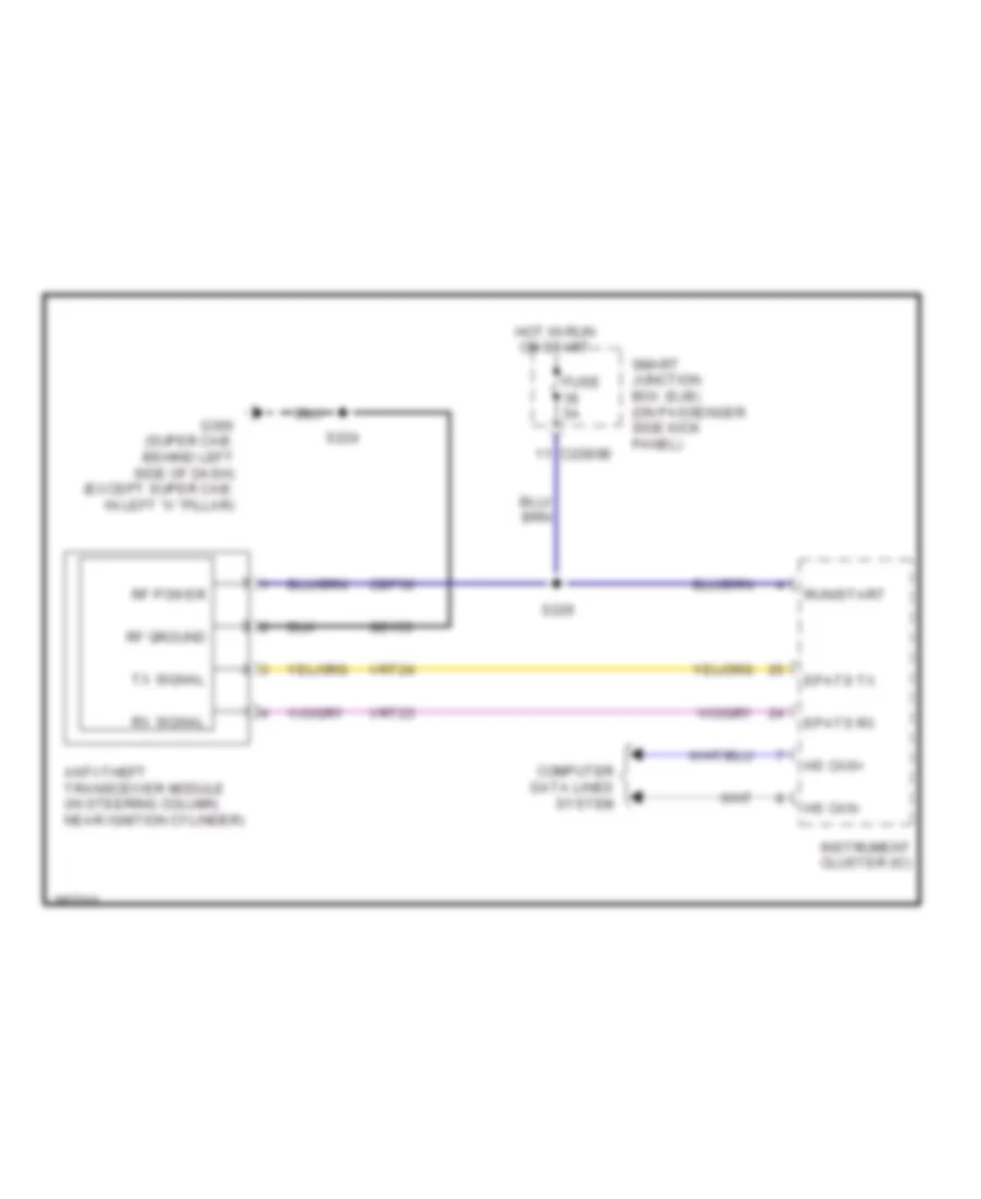
Passive Anti-theft Wiring Diagram for Ford Cab & Chassis F350 Super Duty 2008
 https://portal-diagnostov.com/license.html
Automotive Electricians Portal FZCO
Automotive Electricians Portal FZCO
https://portal-diagnostov.com/license.html
https://portal-diagnostov.com/license.html
Automotive Electricians Portal FZCO
Automotive Electricians Portal FZCOList of elements for Passive Anti-theft Wiring Diagram for Ford Cab & Chassis F350 Super Duty 2008:
- Anti-theft transceiver module (in steering column, near ignition cylinder)
- C2280b
- Cbp36
- Computer data lines system
- Epats rx
- Epats tx
- Fuse 5a
- G300 (super cab: behind left side of dash) (except super cab: in left "a" pillar)
- Gd133
- Hot in run or start
- Hs can+
- Hs can-
- Instrument cluster (ic)
- Rf ground
- Rf power
- Run/start
- Rx signal
- S224
- S226
- Smart junction box (sjb) (on passenger side kick panel)
- Tx signal
- Vrt23
- Vrt24
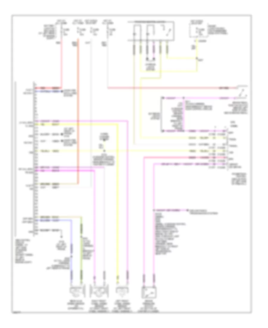
COMPUTER DATA LINES
Computer Data Lines Wiring Diagram for Ford Cab & Chassis F350 Super Duty 2008
 https://portal-diagnostov.com/license.html
Automotive Electricians Portal FZCO
Automotive Electricians Portal FZCO
https://portal-diagnostov.com/license.html
https://portal-diagnostov.com/license.html
Automotive Electricians Portal FZCO
Automotive Electricians Portal FZCOList of elements for Computer Data Lines Wiring Diagram for Ford Cab & Chassis F350 Super Duty 2008:
- (at rear of transfer case) (6.4l) transmission control module (tcm)
- (behind center of dash, behind audio control module) g203
- (in main harness, near breakout behind left side of dash, left of radio opening)
- (near breakout behind audio control module) s212
- (near breakout behind audio control module) s214
- (near breakout behind audio control module) s218
- (near breakout behind left side of dash) s234
- (near breakout behind left side of dash) s238
- (near breakout behind left side of dash) s241
- (near breakout to front left side of transmission, near top)
- (near breakout to master cylinder) s129
- (near breakout to right side of hvac housing) s208
- (near breakout under driver seat) s319
- (near breakout under driver seat) s320
- (near right "c" pillar) s902
- (near right "c" pillar) s903
- (super cab: in body main harness, near breakout under breakout under passenger seat) (regular cab:in body main harness, near breakout to center of cab floor, near rear of cab) (crew cab: in body main harness, near breakout under center console) (others: in body main harness, near breakout to front of right running board) s312
- (super cab: in body main harness, near breakout under breakout under passenger seat) (regular cab:in body main harness, near breakout to center of cab floor, near rear of cab) (crew cab: in body main harness, near breakout under center console) (others: near front of right running board)
- 4x4 control module
- 6.4l
- Abs control module (except 6.4l: at left rear of engine compt) (6.4l: at left side of engine compt)
- Audio control module (acm)
- C1232b
- C175b
- C2280a
- C2280b
- C228a
- C2357a
- C240c
- C240d
- C2463c
- C2500
- C281a
- C310b
- C341c
- C341d
- Cdb08
- Circuit deactivation ignition (cdim) module (behind left side of dash)
- Control module)
- Data link connector (dlc) (behind left side of dash)
- Driver seat module (dsm) (under driver seat)
- Dvd player (on center of inner roof)
- Early production
- Electric heater (6.4l) (at top left of hvac module)
- Except 6.4l
- Feps
- Fuse 15a
- G103 (6.4l) (at right rear of engine compt)
- Gd113
- Gd115
- Hot at all times
- Hs can+
- Hs can-
- Hvac-eatc
- Hvac-emtc
- Instrument cluster (ic)
- Iso
- Late production
- Ms can+
- Ms can-
- Not used
- Parking aid module (at right kick panel)
- Powertrain control module (pcm) (at left side of firewall)
- Restraints control module (rcm) (behind center of dash)
- S1019
- S131 (near breakout to master cylinder)
- S162
- S193
- S215
- S221 (near breakout behind audio control module)
- S222
- S223
- S228
- S230 (near breakout behind audio control module)
- S235
- S236 (near breakout behind left side of dash)
- S313
- Satellite digital audio receiver system (sdars) module (behind glove box)
- Sbp20
- Smart junction box (sjb) (on passenger side kick panel)
- Trailer brake control (tbc) module (behind center of dash)
- Turbocharger actuator (6.4l) (at top left side of engine)
- Vdb04
- Vdb05
- Vdb06
- Vdb07
- Vdb10
COOLING FAN
Cooling Fan Wiring Diagram for Ford Cab & Chassis F350 Super Duty 2008
 https://portal-diagnostov.com/license.html
Automotive Electricians Portal FZCO
Automotive Electricians Portal FZCO
https://portal-diagnostov.com/license.html
https://portal-diagnostov.com/license.html
Automotive Electricians Portal FZCO
Automotive Electricians Portal FZCOList of elements for Cooling Fan Wiring Diagram for Ford Cab & Chassis F350 Super Duty 2008:
- (diesel)
- (diesel) (gas)
- (gas)
- (in engine control sensor & fuel charge harness, near breakout to front right side of engine, on top) s133
- (in engine control sensor harness, near breakout to front right side of engine, on top)
- (in engine control sensor harness, near breakout to right rear of engine compt) s1008
- Battery junction box (bjb) (at left rear of engine compt)
- Brake pressure switch (at bottom of master cylinder)
- C1232b
- C1232e
- C175b
- C175e
- Ce237
- Cec11
- Cht
- Control
- Cylinder head temperature sensor (6.8l: on right cylinder head) (5.4l: at rear of block, under intake)
- Diesel
- Electric fan clutch (at front of engine)
- Engine controls system
- Engine coolant temperature (ect) sensor (diesel) (at front of engine)
- Fuse 10a
- Fuse 20a
- Fuse 50 (gas) 30a fuse 39 (diesel) 50a
- Gas
- Gd119
- Gnd
- Hot at all times
- Kapwr
- Mpr (pcm-rc)
- Nca
- Pcm power relay
- Powertrain control module (pcm) (at left side of firewall)
- Re405
- S1009 (in engine control sensor harness, near breakout to front right side of engine, on top)
- S1013 (in engine control sensor harness, near breakout to front right side of engine, on top)
- S154 s117 (diesel)
- S158 (gas)
- Sbb36
- Sig
- Sig rtn
- Vbpwr
- Ve712
- Ve716
- Vec03
- Vec10
- Vpwr
CRUISE CONTROL
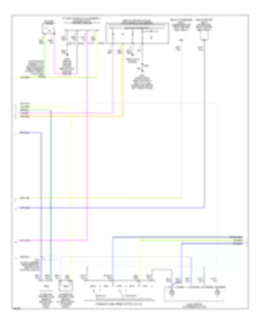
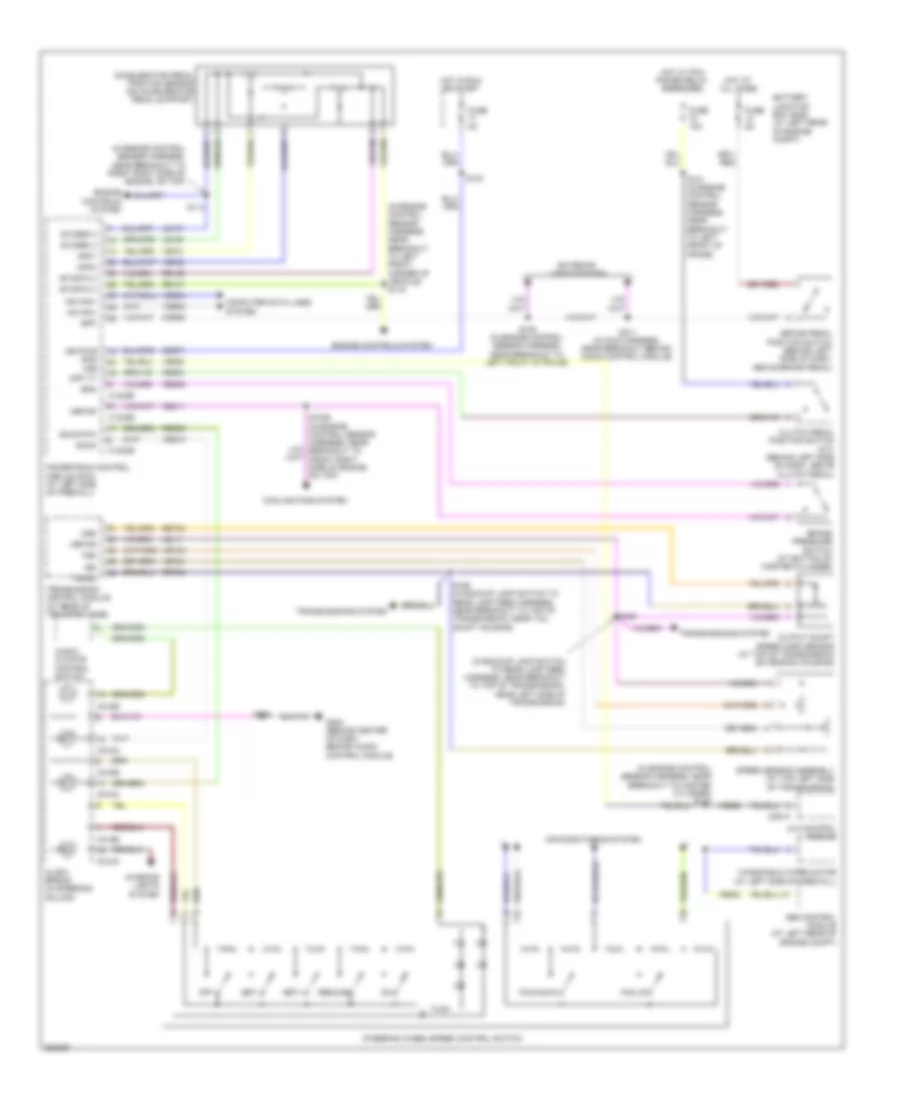
5.4L
5.4L, Cruise Control Wiring Diagram for Ford Cab & Chassis F350 Super Duty 2008
 https://portal-diagnostov.com/license.html
Automotive Electricians Portal FZCO
Automotive Electricians Portal FZCO
https://portal-diagnostov.com/license.html
https://portal-diagnostov.com/license.html
Automotive Electricians Portal FZCO
Automotive Electricians Portal FZCOList of elements for 5.4L, Cruise Control Wiring Diagram for Ford Cab & Chassis F350 Super Duty 2008:
- (at bottom of master cylinder) brake pressure switch
- (at top of transmission extension housing) output shaft speed (oss) sensor
- (in backup lamp switch to rear lamp feed harness, near breakout to front left side of transmission, near top)
- (in engine control sensor harness, near breakout to master cylinder) s130
- 4x4 control module
- Abs control module (at left rear of engine compt)
- Accelerator pedal position sensor (on accelerator pedal support)
- Air conditioning system
- App1
- App2
- App3
- Audio/ climate control switch
- Battery junction box (bjb) (at left rear of engine compt)
- Bpp
- Bps
- Brake pedal position switch (behind left side of dash, above brake pedal)
- C175b
- C175e
- C175t
- C218a
- C218b
- C281a
- Cbb71
- Ccb08
- Ce412
- Ce426
- Ce904
- Ces09
- Clock spring (in steering column)
- Clutch pedal position switch (m/t) (behind left side of dash, above clutch pedal)
- Computer data lines system
- Cpp tt
- Electronic throttle control (etc) motor (on throttle body)
- Etcref
- Etcref1
- Etcrtn
- Etcrtn1
- Exterior lights system
- Fan down
- Fan up
- Fuse 5a
- G103 (at right rear of engine compt)
- G202 (behind center of dash, behind audio control module)
- Hot at all times
- Hot in run or start
- Hs can+
- Hs can-
- Interior lights system
- Isp r
- Iss
- Le111
- Le136
- Le137
- Le428
- Off
- Oss
- Powertrain control module (pcm) (at left side of firewall)
- Re136
- Re137
- Re406
- Re427
- Res08
- Resume
- Ret04
- S106 (in engine control sensor harness, near breakout to left front of frame)
- S123
- S162
- S183
- S196 (in backup lamp switch to rear lamp feed harness, near breakout to front left side of transmission, near top)
- S211 (in main harness, near breakout behind audio control module)
- S239
- Sccs
- Sccs rtn
- Set+
- Set-
- Solid state
- Speed sensor assembly (at top left side of transmission)
- Steering wheel/speed control switch
- T sigrtn
- Tacm n
- Tacm p
- Throttle position sensor (tps) (5.4l: on throttle body) (6.8l: at top center of engine)
- Tp1 ns
- Tp2 ps
- Transmissions system
- Tss
- Vbpwr
- Vdb04
- Vdb05
- Ve701
- Ve702
- Ve703
- Ve744
- Ve818
- Ve819
- Ve822
- Ves10
- Vet33
- Vss
- Windshield wiper motor (at left side of firewall)
6.4L DIESEL
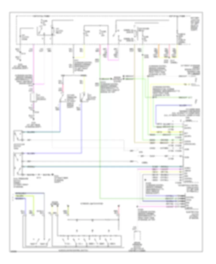
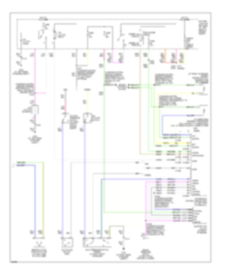
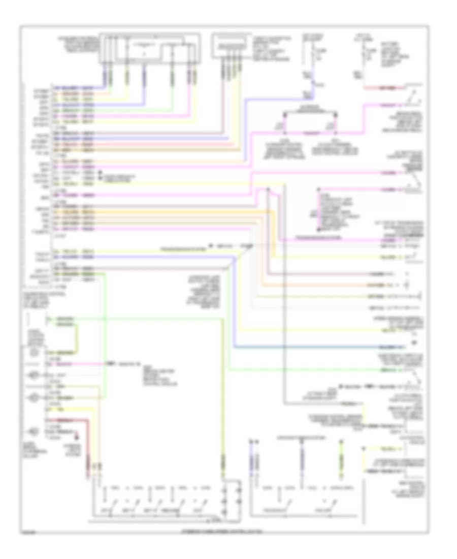
6.4L Diesel, Cruise Control Wiring Diagram for Ford Cab & Chassis F350 Super Duty 2008
 https://portal-diagnostov.com/license.html
Automotive Electricians Portal FZCO
Automotive Electricians Portal FZCO
https://portal-diagnostov.com/license.html
https://portal-diagnostov.com/license.html
Automotive Electricians Portal FZCO
Automotive Electricians Portal FZCOList of elements for 6.4L Diesel, Cruise Control Wiring Diagram for Ford Cab & Chassis F350 Super Duty 2008:
- (in backup lamp switch to rear lamp feed harness, near breakout to top of transmission, near left side of transmission)
- (in engine control sensor harness, near breakout to front right side of engine, on top)
- (in engine control sensor harness, near breakout to left front corner of vehicle) s116
- (in engine control sensor harness, near breakout to master cylinder) s130
- 4x4 control module
- Abs control module (at left rear of engine compt)
- Accelerator pedal position sensor (on accelerator pedal support)
- Air conditioning system
- App1
- App2
- Audio/ climate control switch
- Battery junction box (bjb) (at left rear of engine compt)
- Bpp
- Bps
- Brake pedal position switch (behind left side of dash, above brake pedal)
- Brake pressure switch (at bottom of master cylinder)
- C1232b
- C1232e
- C218a
- C218b
- C281a
- Cbb71
- Ccb08
- Ce904
- Cec11
- Ces09
- Clock spring (in steering column)
- Clutch pedal position switch (m/t) (behind left side of dash, above clutch pedal)
- Computer data lines system
- Cooling fans system
- Cpp tt
- Engine controls system
- Etcref 2
- Etcref 3
- Etcrtn 2
- Etcrtn 3
- Exterior lights system
- Fan down
- Fan up
- Fuse 10a
- Fuse 5a
- G202 (behind center of dash, behind audio control module)
- Hot at all times
- Hot in run or start
- Hot w/ pcm power relay energized
- Hs acn-
- Hs can+
- Interior lights system
- Iss
- Keypwr (r/s) vss
- Le111
- Le136
- Le137
- Off
- Oss
- Output shaft speed (oss) sensor (at top of transmission extension housing)
- Powertrain control module (pcm) (at left side of firewall)
- Re136
- Re137
- Res08
- Resume
- Ret04
- Ret24
- S1009 (in engine control sensor harness, near breakout to front right side of engine, on top)
- S101 (in engine control sensor harness, near breakout to left front of frame)
- S106 (in engine control sensor harness, near breakout to left front of frame)
- S114
- S123
- S196
- S198 (in backup lamp switch to rear lamp feed harness, near breakout to top of transmission, near tail shaft housing)
- S211 (in main harness, near breakout behind audio control module)
- S239
- Sccs
- Sccs rtn
- Set+
- Set-
- Speed sensor assembly (at top left side of transmission)
- Steering wheel/speed control switch
- Transmission control module (at rear of transfer case)
- Transmissions system
- Trgnd
- Tss
- Vbpwr
- Vdb04
- Vdb05
- Ve701
- Ve702
- Ve744
- Ve822
- Ves10
- Vet33
- Windshield wiper motor (at left side of firewall)
6.8L
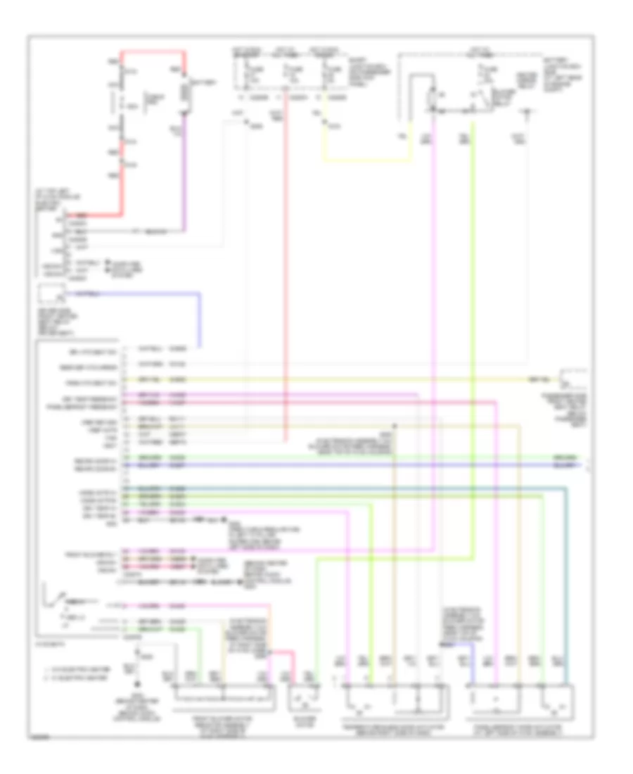
6.8L, Cruise Control Wiring Diagram for Ford Cab & Chassis F350 Super Duty 2008
 https://portal-diagnostov.com/license.html
Automotive Electricians Portal FZCO
Automotive Electricians Portal FZCO
https://portal-diagnostov.com/license.html
https://portal-diagnostov.com/license.html
Automotive Electricians Portal FZCO
Automotive Electricians Portal FZCOList of elements for 6.8L, Cruise Control Wiring Diagram for Ford Cab & Chassis F350 Super Duty 2008:
- (at bottom of master cylinder) brake pressure switch
- (at top of transmission extension housing) output shaft speed (oss) sensor
- (in backup lamp switch to rear lamp feed harness, near breakout to front left side of transmission, near top)
- (in engine control sensor harness, near breakout to master cylinder) s130
- 4x4 control module
- Abs control module (at left rear of engine compt)
- Accelerator pedal position sensor (on accelerator pedal support)
- Air conditioning system
- App1
- App2
- App3
- Audio/ climate control switch
- Battery junction box (bjb) (at left rear of engine compt)
- Bpp
- Bps
- Brake pedal position switch (behind left side of dash, above brake pedal)
- C175b
- C175e
- C175t
- C218a
- C218b
- C281a
- Cbb71
- Ccb08
- Ce412
- Ce426
- Ce904
- Ces09
- Clock spring (in steering column)
- Clutch pedal position switch (m/t) (behind left side of dash, above clutch pedal)
- Computer data lines system
- Cpp tt
- Electronic throttle control (etc) motor (on throttle body)
- Etcref
- Etcref1
- Etcrtn
- Etcrtn1
- Exterior lights system
- Fan down
- Fan up
- Fuse 5a
- G103 (at right rear of engine compt)
- G202 (behind center of dash, behind audio control module)
- Hot at all times
- Hot in run or start
- Hs can+
- Hs can-
- Interior lights system
- Isp r
- Iss
- Le111
- Le136
- Le137
- Le428
- Off
- Oss
- Powertrain control module (pcm) (at left side of firewall)
- Re136
- Re137
- Re406
- Re427
- Res08
- Resume
- Ret04
- S106 (in engine control sensor harness, near breakout to left front of frame)
- S123
- S162
- S183
- S196 (in backup lamp switch to rear lamp feed harness, near breakout to front left side of transmission, near top)
- S211 (in main harness, near breakout behind audio control module)
- S239
- Sccs
- Sccs rtn
- Set+
- Set-
- Solid state
- Speed sensor assembly (at top left side of transmission)
- Steering wheel/speed control switch
- T sigrtn
- Tacm n
- Tacm p
- Throttle position sensor (tps) (5.4l: on throttle body) (6.8l: at top center of engine)
- Tp1 ns
- Tp2 ps
- Transmissions system
- Tss
- Vbpwr
- Vdb04
- Vdb05
- Ve701
- Ve702
- Ve703
- Ve744
- Ve818
- Ve819
- Ve822
- Ves10
- Vet33
- Vss
- Windshield wiper motor (at left side of firewall)
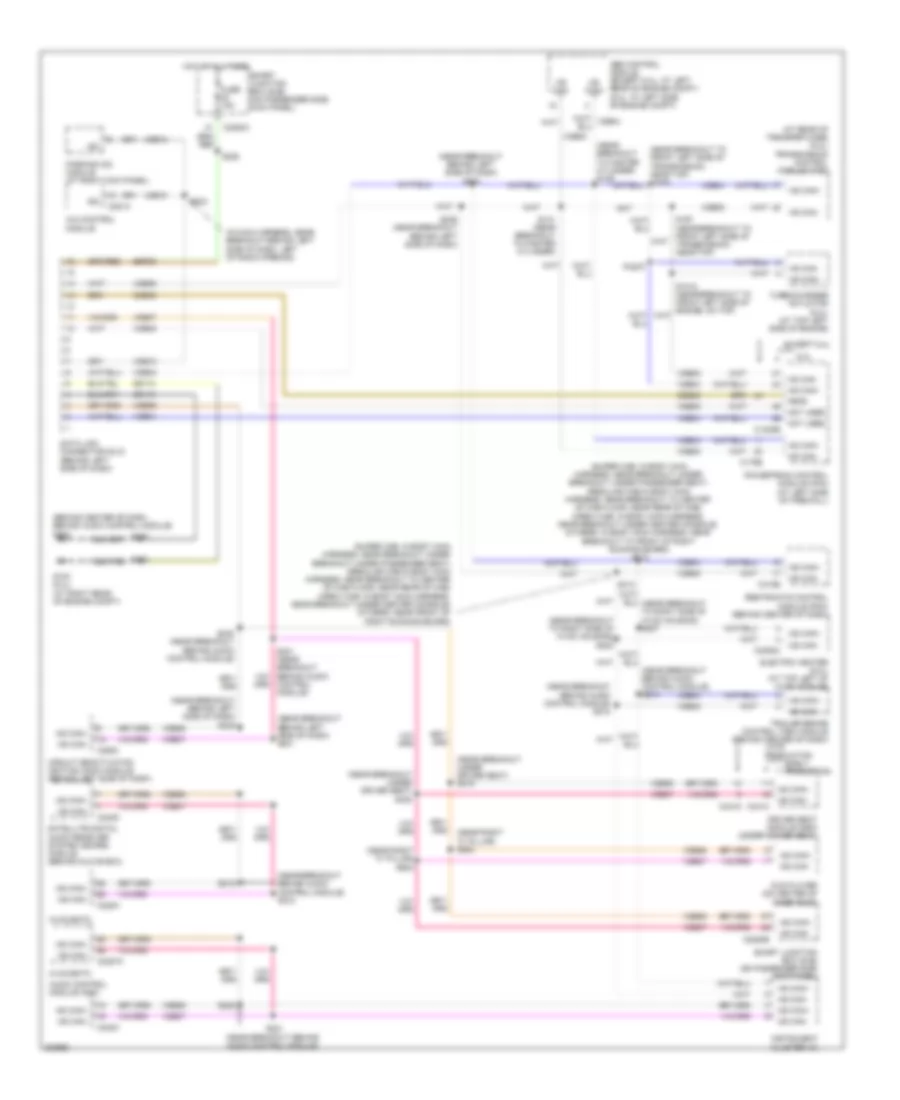
DEFOGGERS
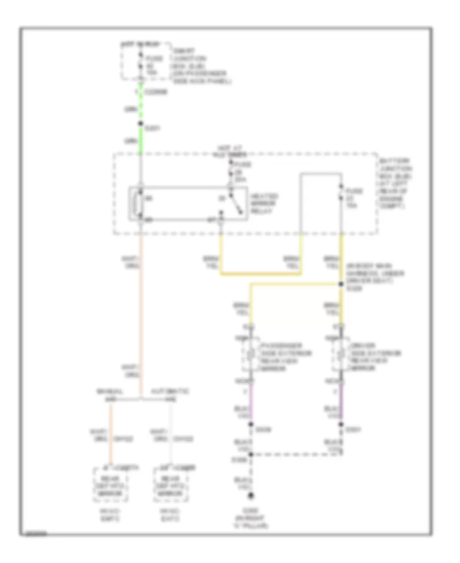
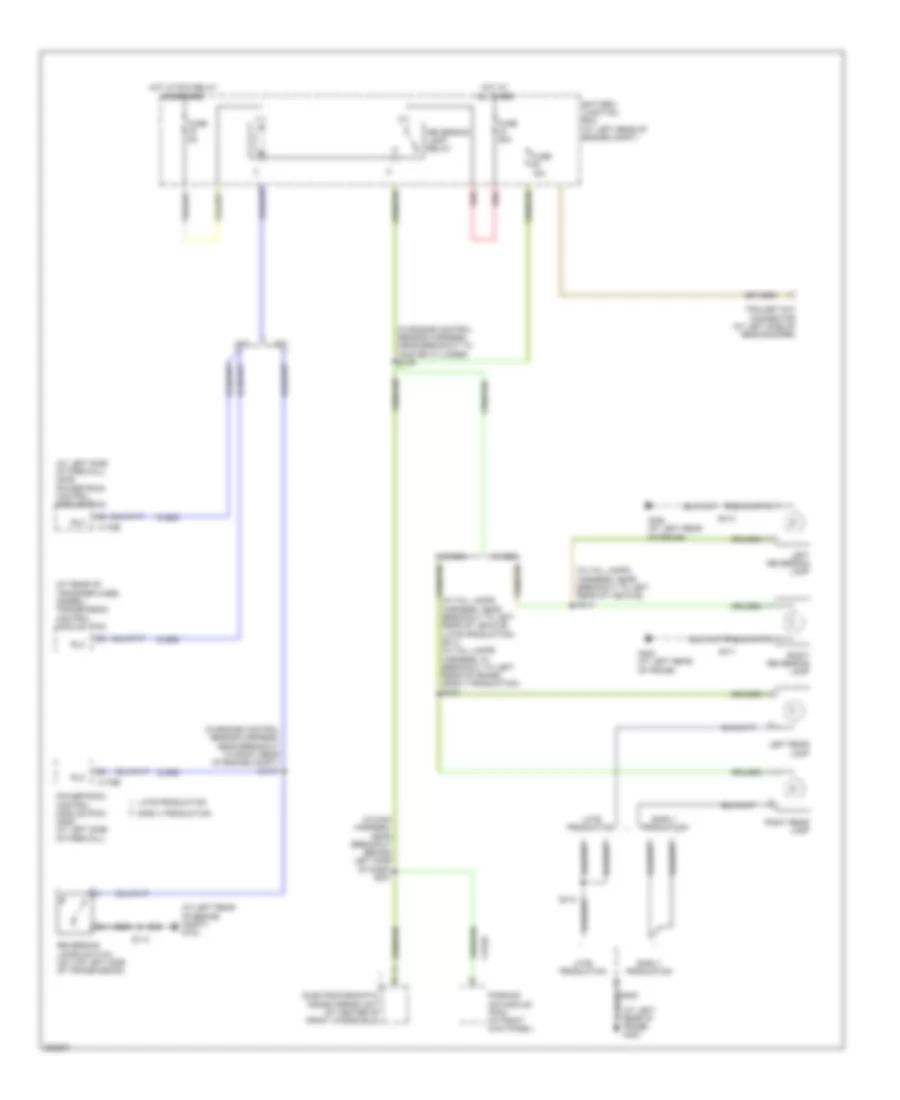
Defoggers Wiring Diagram for Ford Cab & Chassis F350 Super Duty 2008
 https://portal-diagnostov.com/license.html
Automotive Electricians Portal FZCO
Automotive Electricians Portal FZCO
https://portal-diagnostov.com/license.html
https://portal-diagnostov.com/license.html
Automotive Electricians Portal FZCO
Automotive Electricians Portal FZCOList of elements for Defoggers Wiring Diagram for Ford Cab & Chassis F350 Super Duty 2008:
- (in body main harness, under driver seat) s329
- Automatic a/c
- Battery junction box (bjb) (at left rear of engine compt)
- C2280b
- C228b
- C2357a
- Driver side exterior rear view mirror
- Fuse 10a
- Fuse 15a
- Fuse 20a
- G302 (in right "a" pillar)
- Heated mirror relay
- Hot at all times
- Hot in run
- Hvac- eatc
- Hvac- emtc
- Manual a/c
- Nca
- Passenger side exterior rear view mirror
- Rear def htd mirror
- S201
- S308
- S501
- S639
- Smart junction box (sjb) (on passenger side kick panel)
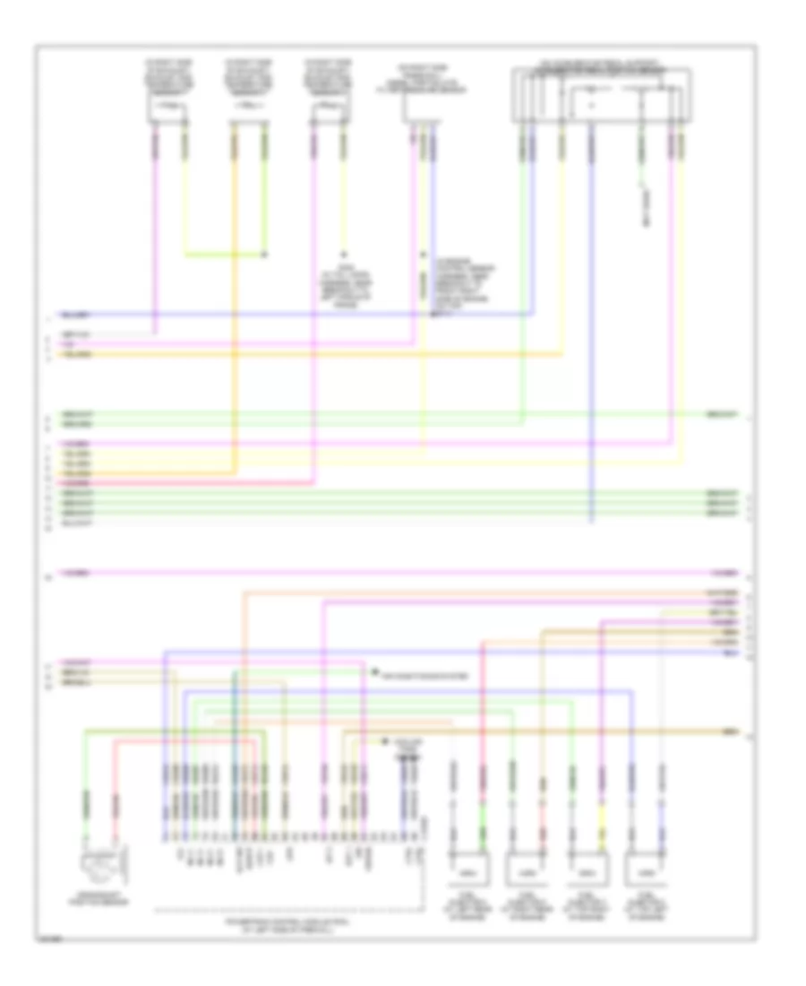
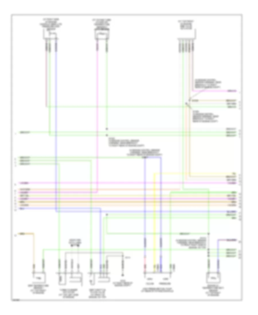
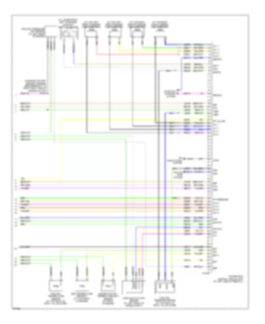
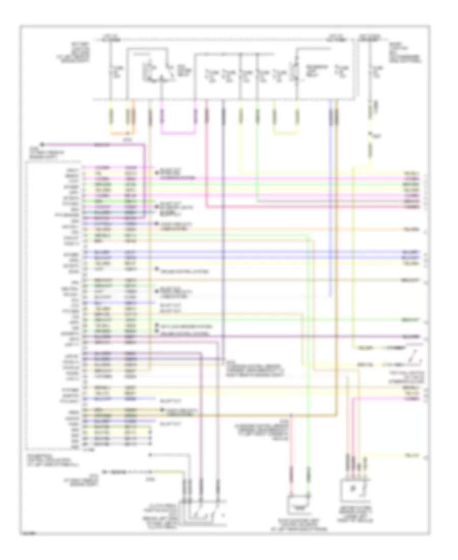
ENGINE PERFORMANCE
5.4L
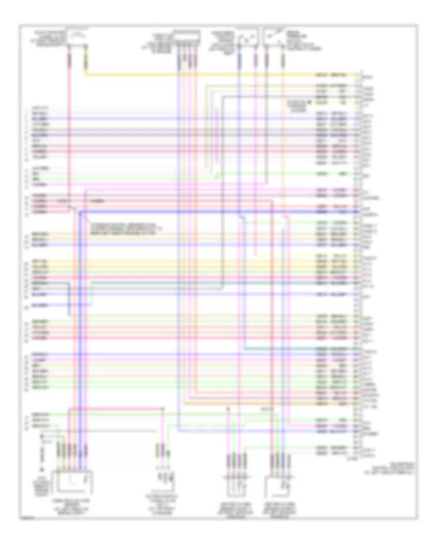
5.4L, Engine Performance Wiring Diagram (1 of 6) for Ford Cab & Chassis F350 Super Duty 2008
 https://portal-diagnostov.com/license.html
Automotive Electricians Portal FZCO
Automotive Electricians Portal FZCO
https://portal-diagnostov.com/license.html
https://portal-diagnostov.com/license.html
Automotive Electricians Portal FZCO
Automotive Electricians Portal FZCOList of elements for 5.4L, Engine Performance Wiring Diagram (1 of 6) for Ford Cab & Chassis F350 Super Duty 2008:
- Anti-lock brakes system
- App1
- App2
- App3
- Battery junction box (bjb) (at left rear of engine compt)
- Boo
- C175b
- C2280b
- Canvnt
- Cat15
- Cbb71
- Cbb76
- Ccb08
- Cdb08
- Cdc12
- Ce114
- Ce237
- Ce326
- Ce903
- Ce904
- Ce912
- Ce913
- Ce914
- Ce924
- Cet21
- Cls05
- Cls28
- Clutch pedal position switch (m/t) (behind left side of dash, above clutch pedal)
- Computer data lines system
- Cpp bt
- Cpp tt
- Cruise control system
- Cto
- Etcref
- Etcrtn
- Evap canister vent control solenoid (at left rear side of frame)
- Exterior lights system
- Fpc
- Fpm
- Ftpt
- Ftptref
- Fuse 10a
- Fuse 15a
- Fuse 20a
- Fuse 30a
- Fuse 5a
- G103 (at right rear of engine compt)
- G106 (at right rear of engine compt)
- Gd113
- Gd164
- Gnd
- Hot at all times
- Hot in run or start
- Hs can +
- Hs can -
- Isp r
- Kapwr
- Le136
- Le137
- Le230
- Nca
- Neutral
- Park
- Pcm power relay
- Pcmrc
- Peps
- Powertrain control module (pcm) (at left side of firewall)
- Pto engage
- Pto okay
- Pto req
- Pto rpm
- Re136
- Re137
- Re407
- Res08
- Reversing lamp relay
- Rlc
- S102 (in engine control sensor harness, near breakout to right rear of engine compt)
- S154
- S158 (in engine control sensor harness, near breakout to left front corner of vehicle)
- S162
- S227
- Sbb36
- Sccs
- Sccsrtn
- Se/smc
- Sigrtnc
- Smart junction box (on passenger side kick panel)
- Tcs
- Tow haul switch (at top of steering column)
- Vdb04
- Vdb05
- Ve225
- Ve518
- Ve701
- Ve702
- Ve703
- Ve822
- Ve922
- Ves10
- Vmc05
- Vpwr1-a
- Vpwr1-b
- Vsout
- Vss
5.4L, Engine Performance Wiring Diagram (2 of 6) for Ford Cab & Chassis F350 Super Duty 2008
 https://portal-diagnostov.com/license.html
Automotive Electricians Portal FZCO
Automotive Electricians Portal FZCO
https://portal-diagnostov.com/license.html
https://portal-diagnostov.com/license.html
Automotive Electricians Portal FZCO
Automotive Electricians Portal FZCOList of elements for 5.4L, Engine Performance Wiring Diagram (2 of 6) for Ford Cab & Chassis F350 Super Duty 2008:
- (in engine control sensor harness, near battery junction box) s156
- (in engine control sensor harness, near breakout to left front of frame) s101
- (on accelerator pedal support) accelerator pedal position sensor
- A/c clutch relay
- A/c compressor cycling switch (at right rear of engine compt, on a/c accumulator)
- A/c high pressure switch (at right side of engine compt)
- Batt
- Battery junction box (bjb) (at left rear of engine compt)
- Ce515
- Ce911
- Computer data lines system
- Fp pwr
- Fpc
- Fpm
- Fpm rtn
- Fuel pump diode
- Fuel pump driver module (at left rear frame rail)
- Fuel pump module
- Fuel pump relay
- Fuel tank pressure (ftp) sensor (above left side of rear axle)
- Fuse 20a
- Fuse 5a
- G108 (at left rear of engine compt)
- G401 (at left rear of frame)
- Gd117
- Hot at all times
- Hot in run or start
- Hs can +
- Hs can -
- Inertia fuel shutoff (ifs) switch (at right kick panel)
- Instrument cluster (ic)
- Le230
- Md grd
- Narrow frame
- Nca
- Re407
- Re515
- Rmc32
- S115
- S123
- S401
- Sender 1
- Sender rtn 2
- Ve225
- Ve518
- Ve922
- Vmc11
- Wide frame
5.4L, Engine Performance Wiring Diagram (3 of 6) for Ford Cab & Chassis F350 Super Duty 2008
 https://portal-diagnostov.com/license.html
Automotive Electricians Portal FZCO
Automotive Electricians Portal FZCO
https://portal-diagnostov.com/license.html
https://portal-diagnostov.com/license.html
Automotive Electricians Portal FZCO
Automotive Electricians Portal FZCOList of elements for 5.4L, Engine Performance Wiring Diagram (3 of 6) for Ford Cab & Chassis F350 Super Duty 2008:
- (in back up lamp switch to rear lamp feed harness, near breakout to front left side of transmission, near top) s194
- (on right side valve cover) heated positive crankcase ventilation (pcv) element
- Anti-lock brakes system
- C175t
- Cca10
- Cca15
- Cdc35
- Cdc38
- Ce233
- Ce234
- Cet05
- Cet06
- Cet07
- Cet08
- Cet09
- Cet22
- Cet25
- Cet49
- Cet50
- Crank
- Heated oxygen sensor (ho2s) 22 (at left side of transmission)
- Ho2s 12
- Ho2s 22
- Htr 12
- Htr 22
- Ignition transformer capacitor 1 (at right front of vehicle)
- Iss
- Le111
- Oss
- Output shaft speed (oss) sensor (at top of transmission extension housing)
- Pc-a
- Pca
- Powertrain control module (pcm) (at left side of firewall)
- Re406
- Ret04
- Ret24
- S196
- Sig rtn
- Sigrtnt
- Smr/start
- Speed sensor assembly (at top left side of transmission)
- Sspc a
- Sspc b
- Sspc c
- Sspc d
- Sspc e
- Sspc-a
- Sspc-b
- Sspc-c
- Sspc-d
- Sspc-e
- Starting/ charging system
- Tcc
- Tft
- Torqshift transmission
- Tr p
- Tr-p
- Tracs
- Tracsil
- Tss
- Vbpwr
- Ve730
- Ve733
- Ve744
- Vet27
- Vet33
- Vpwr
5.4L, Engine Performance Wiring Diagram (4 of 6) for Ford Cab & Chassis F350 Super Duty 2008
 https://portal-diagnostov.com/license.html
Automotive Electricians Portal FZCO
Automotive Electricians Portal FZCO
https://portal-diagnostov.com/license.html
https://portal-diagnostov.com/license.html
Automotive Electricians Portal FZCO
Automotive Electricians Portal FZCOList of elements for 5.4L, Engine Performance Wiring Diagram (4 of 6) for Ford Cab & Chassis F350 Super Duty 2008:
- (at top of left valve cover) coil on plugs (cop) 5, 6, 7 & 8
- (at top of right side valve cover) coil on plugs (cop) 1, 2, 3 & 4
- (in backup lamp switch to rear lamp feed harness, near breakout to front left side of transmission, near top) s183
- (in engine control sensor & fuel charge harness, near breakout to rear left side of engine, on top)
- (in engine control sensor & fuel charge harness, near breakout to rear right side of engine, on top) s108
- Fuel injectors 1,2,3 & 4 (1 & 2: at top right side of engine) (3 & 4: at top right rear of engine)
- Fuel injectors 5,6,7 & 8 (5,6 & 7: at top left side of engine) (8: at top left rear of engine)
- Heated oxygen sensor (ho2s) 12 (at rear of catalytic converter)
- Nca
- Plug spark
- S127 (in engine control sensor & fuel charge harness, near breakout to rear right side of engine, on top)
- S132 (in engine control sensor & fuel charge harness, near breakout to front right side of engine, on top)
- S135
- S181
- Spark plug
5.4L, Engine Performance Wiring Diagram (5 of 6) for Ford Cab & Chassis F350 Super Duty 2008
 https://portal-diagnostov.com/license.html
Automotive Electricians Portal FZCO
Automotive Electricians Portal FZCO
https://portal-diagnostov.com/license.html
https://portal-diagnostov.com/license.html
Automotive Electricians Portal FZCO
Automotive Electricians Portal FZCOList of elements for 5.4L, Engine Performance Wiring Diagram (5 of 6) for Ford Cab & Chassis F350 Super Duty 2008:
- (at front left side of engine) camshaft position (ckp) sensor 2
- (at front right side of engine) camshaft position (ckp) sensor 1
- (at top left rear of engine) knock sensor 2
- (in engine control sensor & fuel charge harness, near breakout to front right side of engine, on top)
- Crankshaft position (cmp) sensor (at lower right side of engine)
- Cylinder head temperature sensor (at rear of block, under intake)
- Fuel rail pressure/ temperature sensor (at top left of intake manifold)
- Ignition transformer capacitor 2 (at right front of vehicle)
- Knock sensor 1 (near rear of intake manifold)
- Nca
- S133 (in engine control sensor & fuel charge harness, near breakout to front right side of engine, on top)
- S134
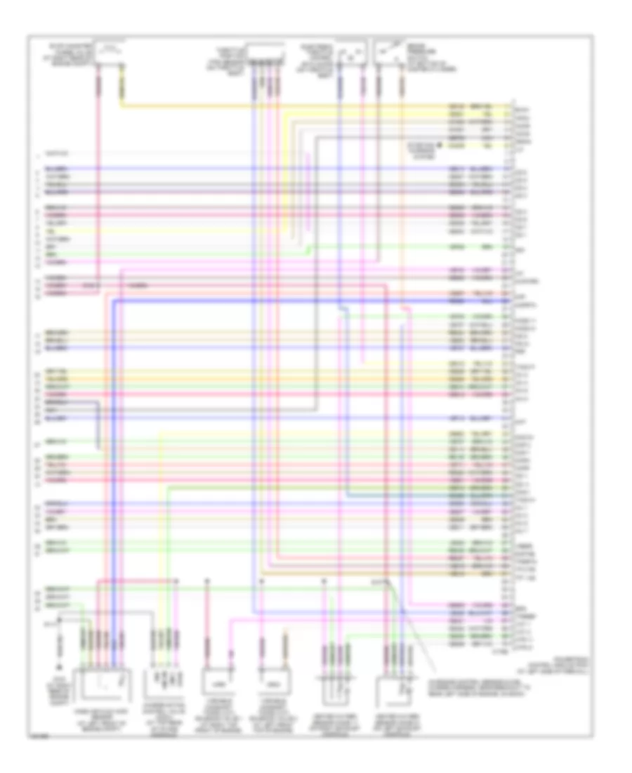
5.4L, Engine Performance Wiring Diagram (6 of 6) for Ford Cab & Chassis F350 Super Duty 2008
 https://portal-diagnostov.com/license.html
Automotive Electricians Portal FZCO
Automotive Electricians Portal FZCO
https://portal-diagnostov.com/license.html
https://portal-diagnostov.com/license.html
Automotive Electricians Portal FZCO
Automotive Electricians Portal FZCOList of elements for 5.4L, Engine Performance Wiring Diagram (6 of 6) for Ford Cab & Chassis F350 Super Duty 2008:
- (in engine control sensor & fuel charge harness, near breakout to rear left side of engine, on back)
- Accr
- Accs
- Bps
- Brake pressure switch (at bottom of master cylinder)
- C175e
- Cac09
- Cd 1
- Cd 2
- Cd 3
- Cd 4
- Cd 5
- Cd 6
- Cd 7
- Cd 8
- Ce114
- Ce132
- Ce205
- Ce206
- Ce207
- Ce208
- Ce209
- Ce210
- Ce211
- Ce212
- Ce235
- Ce236
- Ce303
- Ce304
- Ce305
- Ce306
- Ce307
- Ce308
- Ce309
- Ce310
- Ce321
- Ce412
- Ce421
- Ce422
- Ce426
- Ce608
- Ce918
- Ce923
- Ces09
- Ch302
- Ch421
- Charge motion control valve (cmcv) (at top rear of intake manifold)
- Cht
- Ckpn
- Ckpp
- Cmcv
- Cmcvm
- Cmp 1
- Cmp 2
- De706
- Drain
- Evap canister purge valve (at right rear of engine compt)
- Evmv
- Frp
- Frt
- G103 (at right rear of engine compt)
- Gnd
- Heated oxygen sensor (ho2s) 11 (on right exhaust manifold)
- Heated oxygen sensor (ho2s) 21 (on left exhaust manifold)
- Ho2s 11
- Ho2s 21
- Hpcc
- Htr 11
- Htr 21
- Iat
- Ilc
- Inj 1
- Inj 2
- Inj 3
- Inj 4
- Inj 5
- Inj 6
- Inj 7
- Inj 8
- Injpwrm
- Ks 1+
- Ks 1-
- Ks 2+
- Ks 2-
- Le423
- Le428
- Maf
- Mafrtn
- Mass air flow (maf) sensor (at left front of engine compt)
- Nca
- Powertrain control module (pcm) (at left side of firewall)
- Re135
- Re320
- Re323
- Re324
- Re405
- Re427
- S107
- S114
- S155
- Sigtne
- Solid state
- Starting/ charging system
- Tacm n
- Tacm p
- Throttle position (tps) sensor (on throttle body)
- Tp 1 ns
- Tp 2 ps
- Tpsref
- Tpsrtn
- Variable camshaft timing (vct) solenoid valve 1 (at right top front of engine)
- Variable camshaft timing (vct) solenoid valve 2 (at left front top of engine)
- Vct 1
- Vct 2
- Ve707
- Ve711
- Ve712
- Ve727
- Ve728
- Ve735
- Ve737
- Ve740
- Ve801
- Ve802
- Ve807
- Ve818
- Ve819
- Vpwr
- Vrefe
6.4L DIESEL
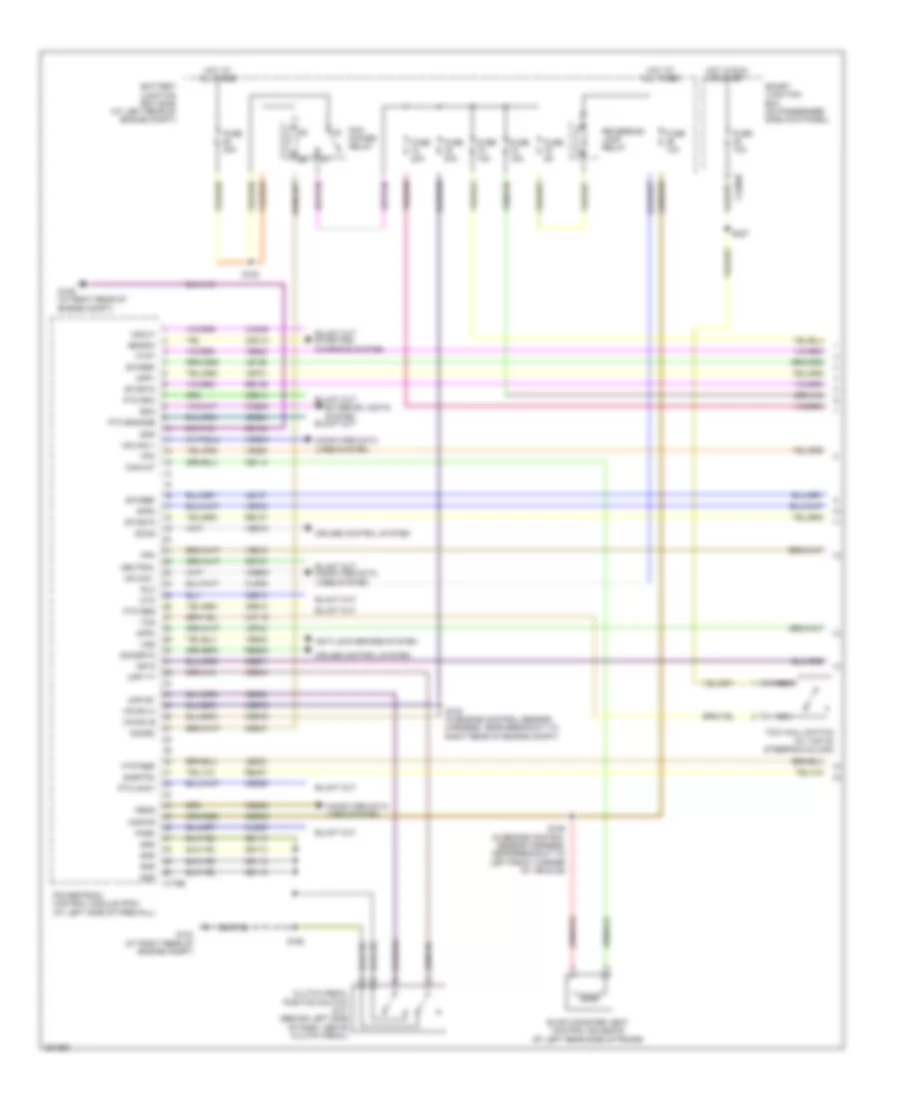
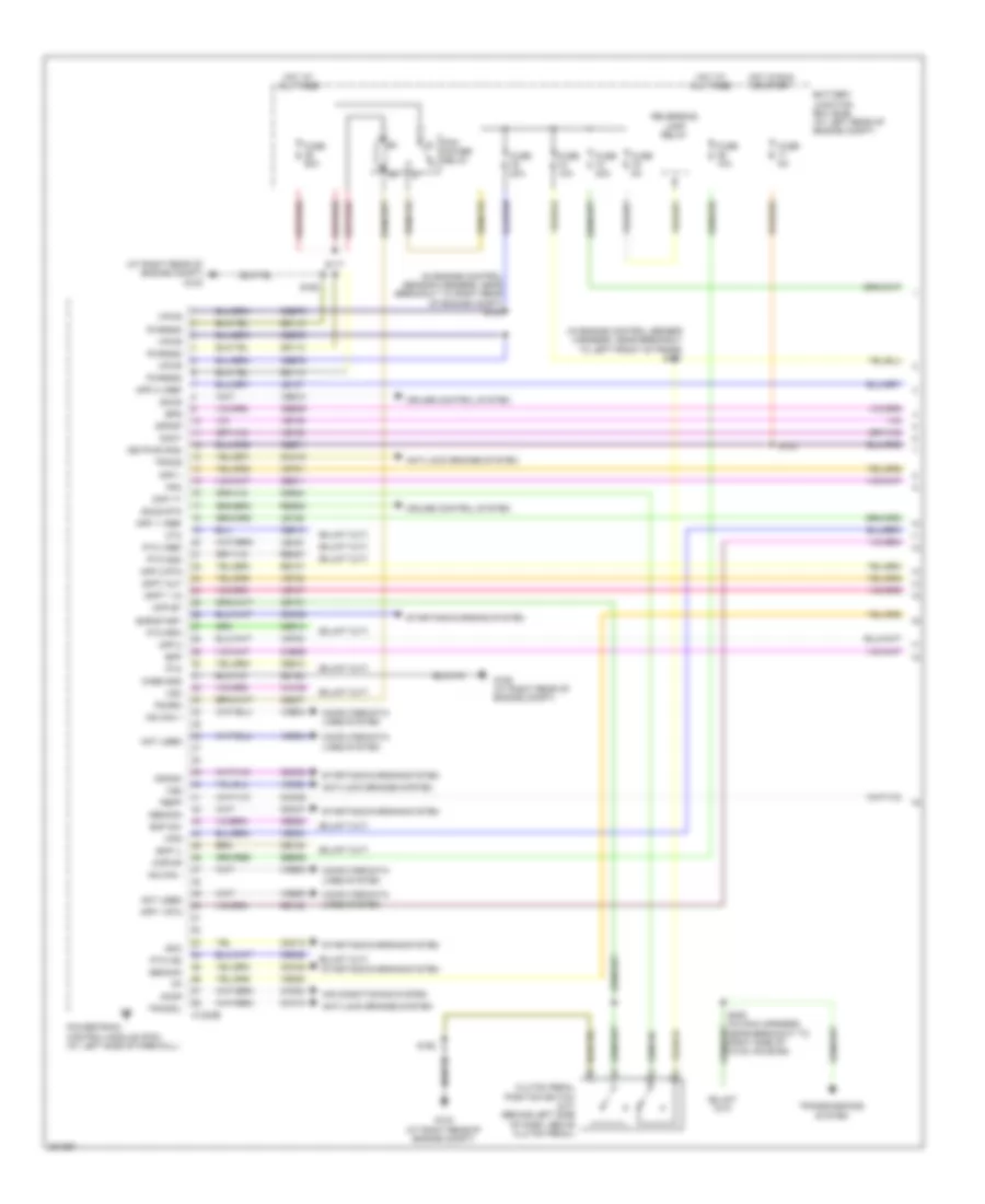
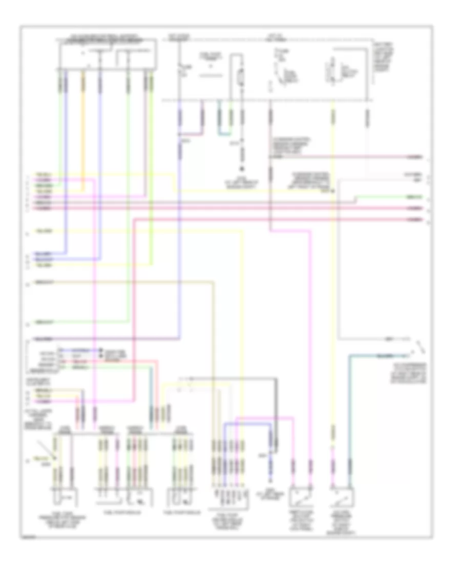
6.4L Diesel, Engine Performance Wiring Diagram (1 of 6) for Ford Cab & Chassis F350 Super Duty 2008
 https://portal-diagnostov.com/license.html
Automotive Electricians Portal FZCO
Automotive Electricians Portal FZCO
https://portal-diagnostov.com/license.html
https://portal-diagnostov.com/license.html
Automotive Electricians Portal FZCO
Automotive Electricians Portal FZCOList of elements for 6.4L Diesel, Engine Performance Wiring Diagram (1 of 6) for Ford Cab & Chassis F350 Super Duty 2008:
- (at right rear of engine compt) g103
- (in engine control sensor harness, near breakout to left front of frame) s101
- (in engine control sensor harness, near breakout to right rear of engine compt) s102
- Accr
- Air conditioning system
- Anti-lock brakes system
- App 1
- App 1 rtn
- App 1 vref
- App 2
- App 2 rtn
- App 2 vref
- Battery junction box (bjb) (at left rear of engine compt)
- Bcp il
- Bcp sw
- Bpp
- Bps
- C1232b
- Case gnd
- Cbb71
- Cbb76
- Cca10
- Cca15
- Ccb06
- Cdc12
- Cdc35
- Cdc38
- Cdc46
- Cdc47
- Ce140
- Ce237
- Ce326
- Ce904
- Ce911
- Ce912
- Ce913
- Ce914
- Ce925
- Ces09
- Cet21
- Ch302
- Clutch pedal position switch (m/t) (behind left side of dash, above clutch pedal)
- Cmc25
- Computer data lines system
- Cpp bt
- Cpp tt
- Crank
- Cruise control system
- Cto
- Doct
- Dpfdp
- Dpft 1 in
- Dpft out
- Fpm
- Fuse 10a
- Fuse 20a
- Fuse 50a
- Fuse 5a
- G103 (at right rear of engine compt)
- G106 (at right rear of engine compt)
- Gd113
- Gd164
- Gencom
- Genmon
- Hot at all times
- Hot in run or start
- Hs can +
- Hs can -
- Kapwr
- Keypwr (r/s)
- Le136
- Le137
- Le434
- Not used
- Pbpp
- Pcm power relay
- Pcmrc
- Powertrain control module (pcm) (at left side of firewall)
- Pto
- Pto gnd
- Pto ind
- Pto rpm
- Pto vref
- Pwrgnd
- Re136
- Re137
- Re327
- Res08
- Reversing lamp relay
- S117
- S123
- S162
- S208 (in main harness, near breakout to right side of hvac housing)
- Sbb36
- Sccs
- Sccs rtn
- Smc
- Smr/start
- Starting/charging system
- Tracs
- Tracsil
- Transmissions system
- Vdb04
- Vdb05
- Ve225
- Ve701
- Ve702
- Ve746
- Ve747
- Ve748
- Ve749
- Ve822
- Ve823
- Ves10
- Vmv05
- Vpwr
- Vso
- Vss
- Wfs
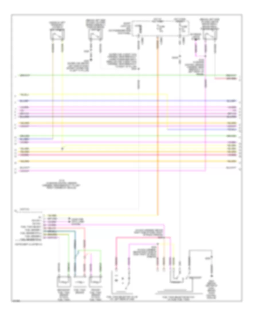
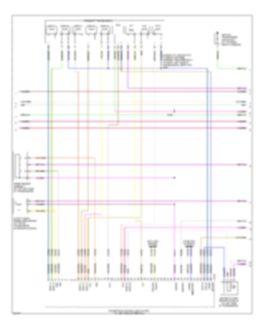
6.4L Diesel, Engine Performance Wiring Diagram (2 of 6) for Ford Cab & Chassis F350 Super Duty 2008
 https://portal-diagnostov.com/license.html
Automotive Electricians Portal FZCO
Automotive Electricians Portal FZCO
https://portal-diagnostov.com/license.html
https://portal-diagnostov.com/license.html
Automotive Electricians Portal FZCO
Automotive Electricians Portal FZCOList of elements for 6.4L Diesel, Engine Performance Wiring Diagram (2 of 6) for Ford Cab & Chassis F350 Super Duty 2008:
- (behind left side of dash, above brake pedal) brake pedal position switch
- (behind left side of dash, on park brake assembly) parking brake switch
- (in main harness, behind right side of dash, right of radio opening)
- (inside of left frame rail) water in fuel sensor
- (super cab: in body main harness, near breakout under passenger seat) (regular cab: in body main harness, near breakout to right "b" pillar) s304
- C2280a
- C2280b
- C2280c
- Computer data lines system
- Exterior lights system
- Fuel sender 1
- Fuel sender 2
- Fuel sender rtn 2
- Fuel tank select
- Fuel tank selector switch (w/ duel fuel tank)
- Fuel tank selector valve (at left rear of cab)
- Fuel tank sensor
- Fuse 10a
- G203 (behind center of dash, behind audio control module)
- G300 (super cab: behind left side of dash) (except super cab: in left "a" pillar)
- Hot at all times
- Hot in run or acc
- Instrument cluster (ic)
- Micro
- Ms can +
- Ms can -
- Primary
- Primary fuel tank sensor (w/ dual fuel tank)
- S106 (in engine control sensor harness, near breakout to left front of frame)
- S116 (in engine control sensor harness, near breakout to left front corner of vehicle)
- S225
- S2439
- S245
- S246 (in main harness, behind right side of dash, right of radio opening)
- S326
- Secondary
- Secondary fuel tank sensor (w/ dual fuel tank)
- Sense
- Smart junction box (on passenger side kick panel)
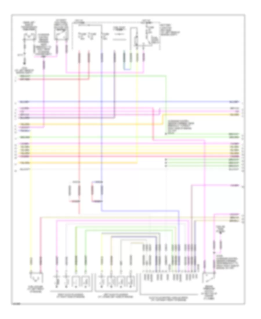
6.4L Diesel, Engine Performance Wiring Diagram (3 of 6) for Ford Cab & Chassis F350 Super Duty 2008
 https://portal-diagnostov.com/license.html
Automotive Electricians Portal FZCO
Automotive Electricians Portal FZCO
https://portal-diagnostov.com/license.html
https://portal-diagnostov.com/license.html
Automotive Electricians Portal FZCO
Automotive Electricians Portal FZCOList of elements for 6.4L Diesel, Engine Performance Wiring Diagram (3 of 6) for Ford Cab & Chassis F350 Super Duty 2008:
- (at right kick panel) inertia fuel shutoff (ifs) switch
- (in engine control sensor harness, near breakout to front right side of engine, on top) s1010
- (in engine control sensor harness, near breakout to right rear of engine compartment) s107
- (near left side of transmission) fuel pump
- Battery junction box (bjb) (at left rear of engine compt)
- Brake pressure switch (at bottom of master cylinder)
- C1273a
- C1273b
- Cbb12
- Ce243
- Ce244
- Ce245
- Ce246
- Ce247
- Ce248
- Ce251
- Ce252
- Ce513
- Ce514
- Cooling fans system
- Fuel cooler (at left front of engine)
- Fuel pump diode
- Fuel pump relay
- Fuse 20a
- Fuse 50a
- Fuse 5a
- G104 (at left rear of engine compt)
- Glow plug control module (gpcm) (at top right front of engine)
- Gpd
- Gpe
- Hot at all times
- Kapwr
- Left glow plug bank (at lower left side of engine)
- Right glow plug bank (at right side of engine)
- S1000
- S1003
- S1009 (in engine control sensor harness, near breakout to front right side of engine, on top)
- S103
- S113
- S124
- Sbb27
- Sbb47
- Vpwr
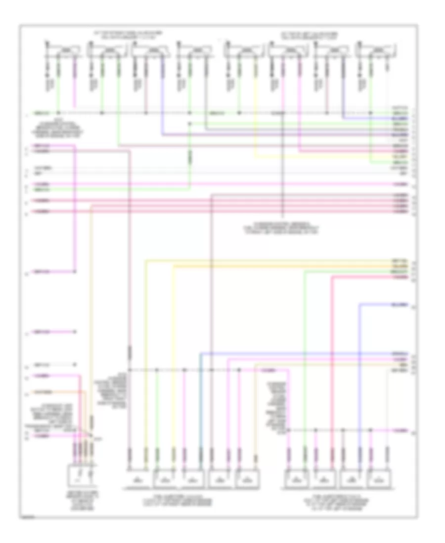
6.4L Diesel, Engine Performance Wiring Diagram (4 of 6) for Ford Cab & Chassis F350 Super Duty 2008
 https://portal-diagnostov.com/license.html
Automotive Electricians Portal FZCO
Automotive Electricians Portal FZCO
https://portal-diagnostov.com/license.html
https://portal-diagnostov.com/license.html
Automotive Electricians Portal FZCO
Automotive Electricians Portal FZCOList of elements for 6.4L Diesel, Engine Performance Wiring Diagram (4 of 6) for Ford Cab & Chassis F350 Super Duty 2008:
- (in engine control sensor harness, near breakout to front right side of engine, on top) s114
- (in right side of exhaust) exhaust gas temperature sensor 1
- (in right side of exhaust) exhaust gas temperature sensor 2
- (in right side of exhaust) exhaust gas temperature sensor 3
- (not used)
- (on accelerator pedal support) accelerator pedal position sensor
- (on right side frame rail) diesel particulate filter pressure sensor
- Acp sw
- Air conditioning system
- C1232e
- Ce250
- Ce315
- Ce514
- Cec11
- Ch425
- Ckp +
- Ckp -
- Cooling fans system
- Crankshaft position sensor
- Ctrl
- Egrvp
- Egt 1
- Fcc
- Fuel injector 2 (at top left of engine)
- Fuel injector 3 (at top right of engine)
- Fuel injector 5 (at right rear of engine)
- Fuel injector 8 (at left rear of engine)
- Gpd
- Iat 2
- Inj 2 -
- Inj 3 -
- Inj 5 -
- Inj 8 -
- Powertrain control module (pcm) (at left side of firewall)
- Re135
- Re206
- Re207
- Re209
- Re212
- Red
- S408 (in tail lamps harness, near breakout to left middle of frame)
- Sig
- Vbpwr
- Ve711
- Ve721
- Ve722
- Ve740
- Vec03
- Vec10
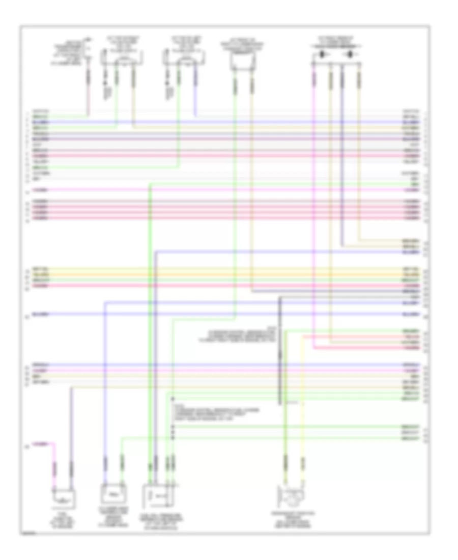
6.4L Diesel, Engine Performance Wiring Diagram (5 of 6) for Ford Cab & Chassis F350 Super Duty 2008
 https://portal-diagnostov.com/license.html
Automotive Electricians Portal FZCO
Automotive Electricians Portal FZCO
https://portal-diagnostov.com/license.html
https://portal-diagnostov.com/license.html
Automotive Electricians Portal FZCO
Automotive Electricians Portal FZCOList of elements for 6.4L Diesel, Engine Performance Wiring Diagram (5 of 6) for Ford Cab & Chassis F350 Super Duty 2008:
- (at intake tube) intake air temperature sensor 2 (iat2) sensor
- (at right side of engine) manifold absolute pressure (map) sensor
- (at top front of engine) egr valve actuator
- (in engine control sensor harness, near breakout to right rear of engine compt)
- (in engine control sensor harness, near breakout to right rear of engine compt) s1007
- C1906a
- C1906b
- Computer data lines system
- Egr temperature sensor 1 (at top front of engine)
- Egr throttle plate valve (at front of engine, on top)
- Engine oil temperature (eot) sensor (at top right of engine)
- G103 (at right rear of engine compt)
- High pressure fuel pump (at rear of intake manifold)
- Pressure
- Red
- S1002 (in engine control sensor harness, near breakout to right rear of engine compt)
- S1005
- S1006 (in engine control sensor harness, near breakout to right rear of engine compt)
- S1013 (in engine control sensor harness, near breakout to front right side of engine, on top)
- S114
- Turbo charger actuator (at top left side of engine)
- Volume
6.4L Diesel, Engine Performance Wiring Diagram (6 of 6) for Ford Cab & Chassis F350 Super Duty 2008
 https://portal-diagnostov.com/license.html
Automotive Electricians Portal FZCO
Automotive Electricians Portal FZCO
https://portal-diagnostov.com/license.html
https://portal-diagnostov.com/license.html
Automotive Electricians Portal FZCO
Automotive Electricians Portal FZCOList of elements for 6.4L Diesel, Engine Performance Wiring Diagram (6 of 6) for Ford Cab & Chassis F350 Super Duty 2008:
- (at lower front left of engine) camshaft position sensor
- (at top left rear of engine) fuel injector 6
- (at top left side of engine) fuel injector 4
- (at top right rear of engine) fuel injector 7
- (at top right side of engine) fuel injector 1
- (in engine control sensor harness, near breakout to front right side of engine, on top) s1012
- Accs
- Air conditioning system
- C1232e
- Cdc10
- Cdc15
- Ce205
- Ce206
- Ce207
- Ce208
- Ce209
- Ce210
- Ce211
- Ce212
- Ce316
- Ce321
- Ce328
- Ch421
- Cmp +
- Cmp -
- Cooling fans system
- Ebp
- Ect
- Egr temperature sensor 2 (at top front of engine)
- Egt 2
- Engine coolant temperature (ect) sensor (at front of engine)
- Eot
- Exhaust pressure (ep) sensor (at left rear of engine)
- Frpi
- Frt
- Fuel rail pressure sensor (at top right of right valve cover)
- Fuel rail temperature sensor (at top right of right valve cover)
- Gd119
- Ge513
- Gencom
- Genmon
- Gnd
- Gpe
- Iat 1
- Inj 1 +
- Inj 1 -
- Inj 2 +
- Inj 3 +
- Inj 4 +
- Inj 4 -
- Inj 5 +
- Inj 6 +
- Inj 6 -
- Inj 7 +
- Inj 7 -
- Inj 8 +
- Le139
- Le423
- Lr139
- Maf
- Maf rtn
- Map
- Mass air flow (maf) sensor (at left front of engine compt)
- Powertrain control module (pcm) (at left side of firewall)
- Pp pressure
- Pp volume
- Re139
- Re205
- Re208
- Re210
- Re211
- Re230
- Re405
- Re406
- Re429
- Red
- Ref
- Rtn
- Sig
- Sig rtn
- Sigrtn
- Starting/ charging system
- Ve607
- Ve706
- Ve716
- Ve717
- Ve726
- Ve727
- Ve728
- Ve740
- Ve803
- Ve921
- Vref
6.8L
6.8L, Engine Performance Wiring Diagram (1 of 6) for Ford Cab & Chassis F350 Super Duty 2008
 https://portal-diagnostov.com/license.html
Automotive Electricians Portal FZCO
Automotive Electricians Portal FZCO
https://portal-diagnostov.com/license.html
https://portal-diagnostov.com/license.html
Automotive Electricians Portal FZCO
Automotive Electricians Portal FZCOList of elements for 6.8L, Engine Performance Wiring Diagram (1 of 6) for Ford Cab & Chassis F350 Super Duty 2008:
- Anti-lock brakes system
- App1
- App2
- App3
- Battery junction box (bjb) (at left rear of engine compt)
- Boo
- C175b
- C2280b
- Canvnt
- Cat15
- Cbb71
- Cbb76
- Ccb08
- Cdb08
- Cdc12
- Ce114
- Ce237
- Ce239
- Ce326
- Ce903
- Ce904
- Ce912
- Ce913
- Ce914
- Ce924
- Cet21
- Cls05
- Cls28
- Clutch pedal position switch (m/t) (behind left side of dash, above clutch pedal)
- Computer data lines system
- Cpp bt
- Cpp tt
- Cruise control system
- Cto
- Etcref
- Etcrtn
- Evap canister vent control solenoid (at left rear side of frame)
- Fpc
- Fpm
- Ftpt
- Ftptref
- Fuse 10a
- Fuse 15a
- Fuse 20a
- Fuse 30a
- Fuse 5a
- G103 (at right rear of engine compt)
- G106 (at right rear of engine compt)
- Gd113
- Gd164
- Gnd
- Heated oxygen sensor (ho2s) 13 (under left front of vehicle)
- Ho2s 13
- Hot at all times
- Hot in run or start
- Hs can +
- Hs can -
- Htr 13
- Isp r
- Kapwr
- Le136
- Le137
- Le230
- Nca
- Neutral
- Park
- Pcm power relay
- Pcmrc
- Peps
- Powertrain control module (pcm) (at left side of firewall)
- Pto engage
- Pto okay
- Pto req
- Pto rpm
- Re136
- Re137
- Re407
- Res08
- Reversing lamp relay
- Rlc
- S102 (in engine control sensor harness, near breakout to right rear of engine compt)
- S154
- S158 (in engine control sensor harness, near breakout to left front corner of vehicle)
- S162
- S227
- Sbb36
- Sccs
- Sccsrtn
- Se/smc
- Sigrtnc
- Smart junction box (on passenger side kick panel)
- Tcs
- Tow haul switch (at top of steering column)
- Vdb04
- Vdb05
- Ve225
- Ve518
- Ve701
- Ve702
- Ve703
- Ve745
- Ve822
- Ve922
- Ves10
- Vmc05
- Vpwr1-a
- Vpwr1-b
- Vsout
- Vss
6.8L, Engine Performance Wiring Diagram (2 of 6) for Ford Cab & Chassis F350 Super Duty 2008
 https://portal-diagnostov.com/license.html
Automotive Electricians Portal FZCO
Automotive Electricians Portal FZCO
https://portal-diagnostov.com/license.html
https://portal-diagnostov.com/license.html
Automotive Electricians Portal FZCO
Automotive Electricians Portal FZCOList of elements for 6.8L, Engine Performance Wiring Diagram (2 of 6) for Ford Cab & Chassis F350 Super Duty 2008:
- (in engine control sensor harness, near battery junction box) s156
- (in engine control sensor harness, near breakout to left front of frame) s101
- (in tail lamps harness, near breakout to cross brace)
- (on accelerator pedal support) accelerator pedal position sensor
- A/c clutch relay
- A/c compressor cycling switch (at right rear of engine compt, on a/c accumulator)
- A/c high pressure switch (at right side of engine compt)
- Batt
- Battery junction box (bjb) (at left rear of engine compt)
- Ce515
- Ce911
- Computer data lines system
- Fp pwr
- Fpc
- Fpm
- Fpm rtn
- Fuel pump diode
- Fuel pump driver module (at left rear frame rail)
- Fuel pump module
- Fuel pump relay
- Fuel tank pressure (ftp) sensor (above left side of rear axle)
- Fuse 20a
- Fuse 5a
- G108 (at left rear of engine compt)
- G400 (at left rear of frame)
- Gd117
- Hot at all times
- Hot in run or start
- Hs can +
- Hs can -
- Inertia fuel shutoff (ifs) switch (at right kick panel)
- Instrument cluster (ic)
- Le230
- Md grd
- Narrow frame
- Nca
- Re407
- Re515
- Rmc32
- S115
- S123
- S401
- S406
- Sender 1
- Sender rtn 2
- Ve225
- Ve518
- Ve922
- Vmc11
- Wide frame
6.8L, Engine Performance Wiring Diagram (3 of 6) for Ford Cab & Chassis F350 Super Duty 2008
 https://portal-diagnostov.com/license.html
Automotive Electricians Portal FZCO
Automotive Electricians Portal FZCO
https://portal-diagnostov.com/license.html
https://portal-diagnostov.com/license.html
Automotive Electricians Portal FZCO
Automotive Electricians Portal FZCOList of elements for 6.8L, Engine Performance Wiring Diagram (3 of 6) for Ford Cab & Chassis F350 Super Duty 2008:
- (in back up lamp switch to rear lamp feed harness, near breakout to front left side of transmission, near top) s194
- Anti-lock brakes system
- C175t
- Cca10
- Cca15
- Cdc35
- Cdc38
- Ce233
- Ce234
- Cet05
- Cet06
- Cet07
- Cet08
- Cet09
- Cet22
- Cet25
- Cet49
- Cet50
- Crank
- Heated oxygen sensor (ho2s) 22 (at left side of transmission)
- Ho2s 12
- Ho2s 22
- Htr 12
- Htr 22
- Ignition transformer capacitor 1 (at top right front of engine)
- Iss
- Le111
- Oss
- Output shaft speed (oss) sensor (at top of transmission extension housing)
- Pc-a
- Pca
- Powertrain control module (pcm) (at left side of firewall)
- Re406
- Ret04
- Ret24
- S196
- Sig rtn
- Sigrtnt
- Smr/start
- Speed sensor assembly (at top left side of transmission)
- Sspc a
- Sspc b
- Sspc c
- Sspc d
- Sspc e
- Sspc-a
- Sspc-b
- Sspc-c
- Sspc-d
- Sspc-e
- Starting/ charging system
- Tcc
- Tft
- Torqshift transmission
- Tr p
- Tr-p
- Tracs
- Tracsil
- Tss
- Vbpwr
- Ve730
- Ve733
- Ve744
- Vet27
- Vet33
- Vpwr
6.8L, Engine Performance Wiring Diagram (4 of 6) for Ford Cab & Chassis F350 Super Duty 2008
 https://portal-diagnostov.com/license.html
Automotive Electricians Portal FZCO
Automotive Electricians Portal FZCO
https://portal-diagnostov.com/license.html
https://portal-diagnostov.com/license.html
Automotive Electricians Portal FZCO
Automotive Electricians Portal FZCOList of elements for 6.8L, Engine Performance Wiring Diagram (4 of 6) for Ford Cab & Chassis F350 Super Duty 2008:
- (at top of left valve cover) coil on plugs (cop) 6, 7, 8 & 9
- (at top of right side valve cover) coil on plugs (cop) 1, 2, 3 & 4
- (in backup lamp switch to rear lamp feed harness, near breakout to front left side of transmission, near top) s183
- (in engine control sensor & fuel charge harness, near breakout to front left side of engine, on top)
- (in engine control sensor & fuel charge harness, near breakout to rear left side of engine, on top) s136
- Fuel injectors 1,2,3,4 & 5 (1,2 & 5: at top right side of engine) (3 & 4: at top right rear of engine)
- Fuel injectors 6,7,8 & 10 (6 & 7: at top left side of engine) (8: at top left rear of engine) (10: at top left of engine)
- Heated oxygen sensor (ho2s) 12 (at rear of catalytic converter)
- Nca
- Plug spark
- S127 (in engine control sensor & fuel charge harness, near rear right side of engine, on top)
- S132 (in engine control sensor & fuel charge harness, near breakout to front right side of engine, on top)
- S135
- S181
- Spark plug
6.8L, Engine Performance Wiring Diagram (5 of 6) for Ford Cab & Chassis F350 Super Duty 2008
 https://portal-diagnostov.com/license.html
Automotive Electricians Portal FZCO
Automotive Electricians Portal FZCO
https://portal-diagnostov.com/license.html
https://portal-diagnostov.com/license.html
Automotive Electricians Portal FZCO
Automotive Electricians Portal FZCOList of elements for 6.8L, Engine Performance Wiring Diagram (5 of 6) for Ford Cab & Chassis F350 Super Duty 2008:
- (at front of right cylinder bank) camshaft position sensor 1
- (at right rear of cylinder head) dual knock sensor
- (at top of left valve cover) coil on plugs (cop) 10
- (at top of right valve cover) coil on plugs (cop) 5
- Crankshaft position sensor (on lower front center of engine)
- Cylinder head temperature sensor (on right cylinder head)
- Fuel injector (at top left of engine)
- Fuel rail pressure/ temperature sensor (at top left of intake manifold)
- Ignition transformer capacitor 2 (at top front of left cylinder head)
- Nca
- S133 (in engine control sensor & fuel charge harness, near breakout to front right side of engine, on top)
- S134 (in engine control sensor & fuel charge harness, near breakout to front right side of engine, on top)
- Spark plug
6.8L, Engine Performance Wiring Diagram (6 of 6) for Ford Cab & Chassis F350 Super Duty 2008
 https://portal-diagnostov.com/license.html
Automotive Electricians Portal FZCO
Automotive Electricians Portal FZCO
https://portal-diagnostov.com/license.html
https://portal-diagnostov.com/license.html
Automotive Electricians Portal FZCO
Automotive Electricians Portal FZCOList of elements for 6.8L, Engine Performance Wiring Diagram (6 of 6) for Ford Cab & Chassis F350 Super Duty 2008:
- (in engine control sensor & fuel charge harness, near breakout to rear left side of engine, on top)
- Accr
- Accs
- Bps
- Brake pressure switch (at bottom of master cylinder)
- C175e
- Cac09
- Cd 1
- Cd 10
- Cd 2
- Cd 3
- Cd 4
- Cd 5
- Cd 6
- Cd 7
- Cd 8
- Cd 9
- Ce132
- Ce205
- Ce206
- Ce207
- Ce208
- Ce209
- Ce210
- Ce211
- Ce212
- Ce213
- Ce214
- Ce235
- Ce236
- Ce303
- Ce304
- Ce305
- Ce306
- Ce307
- Ce308
- Ce309
- Ce310
- Ce311
- Ce312
- Ce316
- Ce412
- Ce426
- Ce608
- Ces09
- Ch302
- Ch421
- Cht
- Ckpn
- Ckpp
- Cmp 1
- De706
- Drain
- Etcref1
- Etcrtn1
- Evap canister purge valve (at right rear of engine compt)
- Evmv
- Frp
- Frt
- G103 (at right rear of engine compt)
- Gnd
- Heated oxygen sensor (ho2s) 11 (on right exhaust manifold)
- Heated oxygen sensor (ho2s) 21 (on left exhaust manifold)
- Ho2s 11
- Ho2s 21
- Htr 11
- Htr 21
- Iat
- Ilc
- Imtv
- Inj 1
- Inj 10
- Inj 2
- Inj 3
- Inj 4
- Inj 5
- Inj 6
- Inj 7
- Inj 8
- Inj 9
- Injpwrm
- Intake manifold tuning valve (imtv) (at top right of engine)
- Ks 1+
- Ks 1-
- Ks 2+
- Ks 2-
- Le423
- Le428
- Maf
- Mafrtn
- Mass air flow (maf) sensor (at left front of engine compt)
- Nca
- Powertrain control module (pcm) (at left side of firewall)
- Re135
- Re320
- Re323
- Re324
- Re405
- Re427
- S107
- S114
- S155
- Sigtne
- Solid state
- Starting/ charging system
- Tacm n
- Tacm p
- Throttle position (tps) sensor (at top center of engine)
- Tp 1 ns
- Tp 2 ps
- Ve706
- Ve711
- Ve712
- Ve727
- Ve728
- Ve735
- Ve737
- Ve740
- Ve801
- Ve802
- Ve807
- Ve818
- Ve819
- Vpwr
- Vrefe
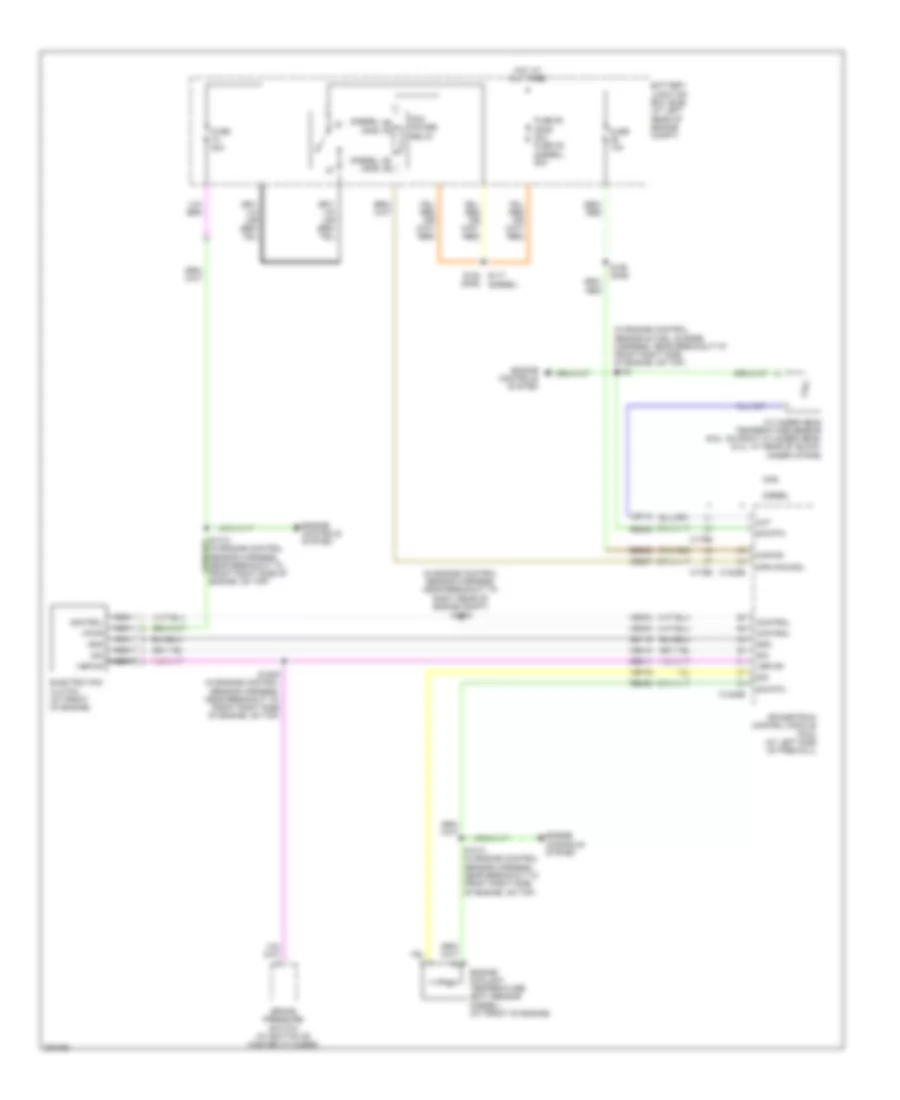
EXTERIOR LIGHTS
Backup Lamps Wiring Diagram for Ford Cab & Chassis F350 Super Duty 2008
 https://portal-diagnostov.com/license.html
Automotive Electricians Portal FZCO
Automotive Electricians Portal FZCO
https://portal-diagnostov.com/license.html
https://portal-diagnostov.com/license.html
Automotive Electricians Portal FZCO
Automotive Electricians Portal FZCOList of elements for Backup Lamps Wiring Diagram for Ford Cab & Chassis F350 Super Duty 2008:
- (at left rear of engine compt) g104
- (at left rear of frame) g400
- (at left side of firewall) (gas) powertrain control module (pcm)
- (at rear of transfer case) (diesel) transmisson control module (tcm)
- (in engine control sensor harness, near breakout to master cylinder) s109
- (in engine control sensor harness, near breakout to right rear of engine compt) s1777
- (in main harness, near breakout behind left side of dash) s237
- (in tail lamps harness, near breakout to left rear of vehicle) (late production) s414 (in tail lamps harness, in breakout to left rear of frame) (early production) s403
- (in tail lamps harness, near breakout to left rear of vehicle) s414
- A/t
- Battery junction box (at left rear of engine compt)
- C175b
- Cls10
- Cls28
- Early production
- Electrochromatic inside mirror unit (at center of front windshield)
- Fuse 15a
- Fuse 20a
- Fuse 5a
- G400 (at left rear of frame)
- Hot at all times
- Hot w/ pcm relay energized
- Late production
- Left rear lamp
- Left reversing lamp
- M/t
- Parking aid module (pam) (at right kick panel)
- Powertrain control module (pcm) (gas) (at left side of firewall)
- Red
- Reversing lamp relay
- Reversing lamps switch (on top left side of transmission)
- Right rear lamp
- Right reversing lamp
- Rlc
- S113
- S400
- S411
- S413
- Trailer tow connector (at left side of rear bumper)
- W/ box
- W/o box
Exterior Lamps Wiring Diagram, with Box (1 of 2) for Ford Cab & Chassis F350 Super Duty 2008
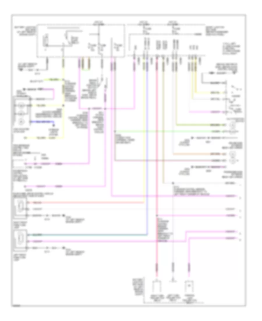 https://portal-diagnostov.com/license.html
Automotive Electricians Portal FZCO
Automotive Electricians Portal FZCO
https://portal-diagnostov.com/license.html
https://portal-diagnostov.com/license.html
Automotive Electricians Portal FZCO
Automotive Electricians Portal FZCOList of elements for Exterior Lamps Wiring Diagram, with Box (1 of 2) for Ford Cab & Chassis F350 Super Duty 2008:
- (at left rear of engine compt) g104
- (behind center of dash, behind audio control module) g203
- 1) full left 2) lane change 3) neutral 4) lane change 5) full right
- Battery junction box (bjb) (at left rear of engine compt)
- Boo
- Brake pedal position switch (behind left side of dash, above brake pedal)
- C1232b
- C175b
- C2280b
- C2280d
- C2280f
- C281b
- Ccb08
- Cls43
- Diesel
- Driver side exterior rear view mirror
- Four-wheel drive control module (behind right side of dash)
- Fuse 15a
- Fuse 20a
- Fuse 5a
- G104 (at left rear of engine compt)
- G108 (at left rear of engine compt)
- G302 (in right "a" pillar)
- Gas
- Haz
- Hazard
- High mounted stoplamp
- Hot at all times
- Interior lights system
- Left front park/turn lamp
- Left turn trailer tow relay
- Lf turn lp
- Lp/lh mir
- Lp/rh mir
- Lr stop turn lp
- Lts
- Micro
- Multi-function switch
- Parking lamp trailer tow relay
- Passenger side exterior rear view mirror
- Powertrain control module (pcm) (at left side of firewall)
- Rf turn lp
- Right front park/turn lamp
- Right turn trailer tow relay
- Rr stop turn lp
- Rts
- S106 (in engine control sensor harness, near breakout to left front of frame)
- S110 (in engine control sensor harness, near breakout to left front corner of vehicle)
- S111 (in engine control sensor harness, near breakout to left front corner of vehicle)
- S112 (in engine control sensor harness, near breakout to master cylinder)
- S113
- S115
- S211 (in main harness, near breakout behind audio control module)
- S229 (in main harness, near breakout behind audio control module)
- S235
- S323
- S329 (in body main harness, under driver seat)
- S501
- S639
- Smart junction box (sjb) (behind passenger side kick panel)
- Stop lamp relay
- Trailer brake control (tbc) module (behind center of dash)
- Turn signal
Exterior Lamps Wiring Diagram, with Box (2 of 2) for Ford Cab & Chassis F350 Super Duty 2008
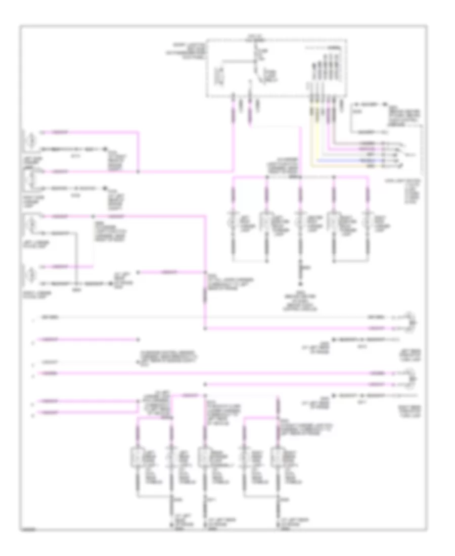 https://portal-diagnostov.com/license.html
Automotive Electricians Portal FZCO
Automotive Electricians Portal FZCO
https://portal-diagnostov.com/license.html
https://portal-diagnostov.com/license.html
Automotive Electricians Portal FZCO
Automotive Electricians Portal FZCOList of elements for Exterior Lamps Wiring Diagram, with Box (2 of 2) for Ford Cab & Chassis F350 Super Duty 2008:
- (at left rear of frame) g400
- (in engine control sensor harness, near breakout to left rear of engine compt) s121
- (in left marker lamp (pia) harness, in breakout to left rear of vehicle) s423
- (in marker lamp-to-switch harness, near front of roof) s906
- 1) auto 2) off 3) park 4) head 5) fog
- Autolamp on
- C2280b
- C2280d
- C2280e
- Center roof marker lamp
- Fog lamp
- Fuse 15a
- G104 (at right rear of engine compt)
- G108 (at left rear of engine compt)
- G203 (behind center of dash, behind audio control module)
- G400 (at left rear of frame)
- Headlamp
- Headlamp off
- Hot at all times
- Left center roof marker lamp
- Left license plate lamp
- Left rear park/stop turn lamp
- Left rear side lamp 1 (w/ dual rear wheels)
- Left rear side lamp 2 (w/ dual rear wheels)
- Left roof marker lamp
- Left side marker lamp
- Main light switch
- Micro
- Park lamp relay
- Parklamp on
- Rear marker lamp assemblly (w/ dual rear wheels)
- Right center roof marker lamp
- Right license plate lamp
- Right rear park/stop turn lamp
- Right rear side lamp 1 (w/ dual rear wheels)
- Right rear side lamp 2 (w/ dual rear wheels)
- Right roof marker lamp
- Right side marker lamp
- S113
- S128
- S235
- S402 (in tail lamps harness, in breakout to left rear of frame)
- S411
- S412 (in backup alarm jumper harness, in breakout to left rear of vehicle)
- S413
- S424 (in right marker lamp (pia) harness, in breakout to left rear of frame)
- S426
- S905
- S906 (in marker lamp-to-switch harness, near front of roof)
- Smart junction box (sjb) (on passenger side kick panel)
Exterior Lamps Wiring Diagram, without Box (1 of 2) for Ford Cab & Chassis F350 Super Duty 2008
 https://portal-diagnostov.com/license.html
Automotive Electricians Portal FZCO
Automotive Electricians Portal FZCO
https://portal-diagnostov.com/license.html
https://portal-diagnostov.com/license.html
Automotive Electricians Portal FZCO
Automotive Electricians Portal FZCOList of elements for Exterior Lamps Wiring Diagram, without Box (1 of 2) for Ford Cab & Chassis F350 Super Duty 2008:
- (at left rear of engine compt) g104
- (behind center of dash, behind audio control module) g203
- 1) full left 2) lane change 3) neutral 4) lane change 5) full right
- Battery junction box (bjb) (at left rear of engine compt)
- Boo
- Brake pedal position switch (behind left side of dash, above brake pedal)
- C1232b
- C175b
- C2280b
- C2280d
- C2280f
- C281b
- Ccb08
- Cls43
- Diesel
- Driver side exterior rear view mirror
- Four-wheel drive control module (behind right side of dash)
- Fuse 15a
- Fuse 20a
- Fuse 5a
- G104 (at left rear of engine compt)
- G108 (at left rear of engine compt)
- G302 (in right "a" pillar)
- Gas
- Haz
- High mounted stoplamp
- Hot at all times
- Interior lights system
- Left front park/turn lamp
- Left turn trailer tow relay
- Lf turn lp
- Lp/lh mir
- Lp/rh mir
- Lr stop turn lp
- Lts
- Micro
- Multi-function switch
- Parking lamp trailer tow relay
- Passenger side exterior rear view mirror
- Powertrain control module (pcm) (at left side of firewall)
- Rf turn lp
- Right front park/turn lamp
- Right turn trailer tow relay
- Rr stop turn lp
- Rts
- S106 (in engine control sensor harness, near breakout to left front of frame)
- S110 (in engine control sensor harness, near breakout to left front corner of vehicle)
- S111 (in engine control sensor harness, near breakout to left front corner of vehicle)
- S112 (in engine control sensor harness, near breakout to master cylinder)
- S113
- S115
- S211 (in main harness, near breakout behind audio control module)
- S229 (in main harness, near breakout behind audio control module)
- S235
- S323
- S329 (in body main harness, under driver seat)
- S501
- S639
- Smart junction box (sjb) (on passenger side kick panel)
- Stop lamp relay
- Trailer brake control (tbc) module (behind center of dash)
Exterior Lamps Wiring Diagram, without Box (2 of 2) for Ford Cab & Chassis F350 Super Duty 2008
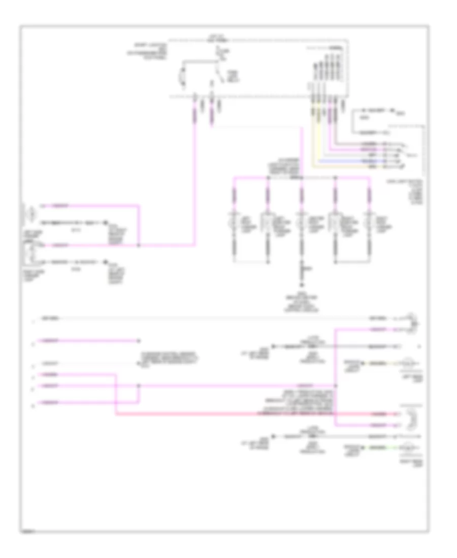 https://portal-diagnostov.com/license.html
Automotive Electricians Portal FZCO
Automotive Electricians Portal FZCO
https://portal-diagnostov.com/license.html
https://portal-diagnostov.com/license.html
Automotive Electricians Portal FZCO
Automotive Electricians Portal FZCOList of elements for Exterior Lamps Wiring Diagram, without Box (2 of 2) for Ford Cab & Chassis F350 Super Duty 2008:
- (early production)
- (in engine control sensor harness, near breakout to left rear of engine compt) s121
- (in marker lamp-to-switch harness, near front of roof) s906
- (late production)
- (late production) s413
- Autolamp on
- Backup lamps circuit
- C2280b
- C2280d
- C2280e
- Center roof marker lamp
- Fog lamp
- Fuse 15a
- G104 (at right rear of engine compt)
- G108 (at left rear of engine compt)
- G203
- G203 (behind center of dash, behind audio control module)
- G400 (at left rear of frame)
- Headlamp
- Headlamp off
- Hot at all times
- Left center roof marker lamp
- Left rear lamp
- Left roof marker lamp
- Left side marker lamp
- Main light switch 1) auto 2) off 3) park 4) head 5) fog
- Micro
- Park lamp relay
- Parklamp on
- Right center roof marker lamp
- Right rear lamp
- Right roof marker lamp
- Right side marker lamp
- S113
- S128
- S235
- S400 (early production)
- S403 (in tail lamps harness, in breakout to left rear of frame) s412 (in backup alarm jumper harness, in breakout to left rear of vehicle)
- Smart junction box (on passenger side kick panel)
Trailer/Camper Adapter Wiring Diagram for Ford Cab & Chassis F350 Super Duty 2008
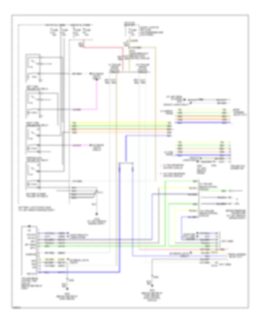 https://portal-diagnostov.com/license.html
Automotive Electricians Portal FZCO
Automotive Electricians Portal FZCO
https://portal-diagnostov.com/license.html
https://portal-diagnostov.com/license.html
Automotive Electricians Portal FZCO
Automotive Electricians Portal FZCOList of elements for Trailer/Camper Adapter Wiring Diagram for Ford Cab & Chassis F350 Super Duty 2008:
- (at left rear of frame) g400
- (behind center of dash, behind audio control module)
- (not used)
- (not used) c2142
- B+brake
- Backup lamps circuit
- Battery charge trailer tow relay
- Battery junction box (bjb) (at left rear of engine compt)
- Boo
- Bpt sens
- Bpt+
- Bpt-
- Brake control module
- Brake pressure transducer (at left rear of engine compt)
- C2142
- C2280b
- Cat19
- Cbp33
- Cls43
- Computer data lines system
- Control module
- Exterior lights circuit
- Fuse 10a
- Fuse 25a
- Fuse 30a
- G104 (at left rear of engine compt)
- G203
- G400 (at left rear of frame)
- Gd115
- Gnd
- Hot at all times
- Hot in on or start
- Hs can+
- Hs can-
- Lca16
- Left turn trailer tow relay
- Parking lamp trailer tow relay
- R/s
- Rca16
- Red
- Right turn trailer tow relay
- S113
- S203 (behind center of dash, behind
- S225
- S400
- Sbb05
- Smart junction box (sjb) (on passenger side kick panel)
- Tbc out
- Trailer brake control (tbc) module (behind center of dash)
- Trailer tow connector
- Vca13
- Vdb04
- Vdb05
- W/ narrow frame
- W/ trailer
- W/ trailer brake
- W/ trailer brake control module
- W/ wide frame
- W/o trailer brake control module
GROUND DISTRIBUTION
Ground Distribution Wiring Diagram (1 of 5) for Ford Cab & Chassis F350 Super Duty 2008
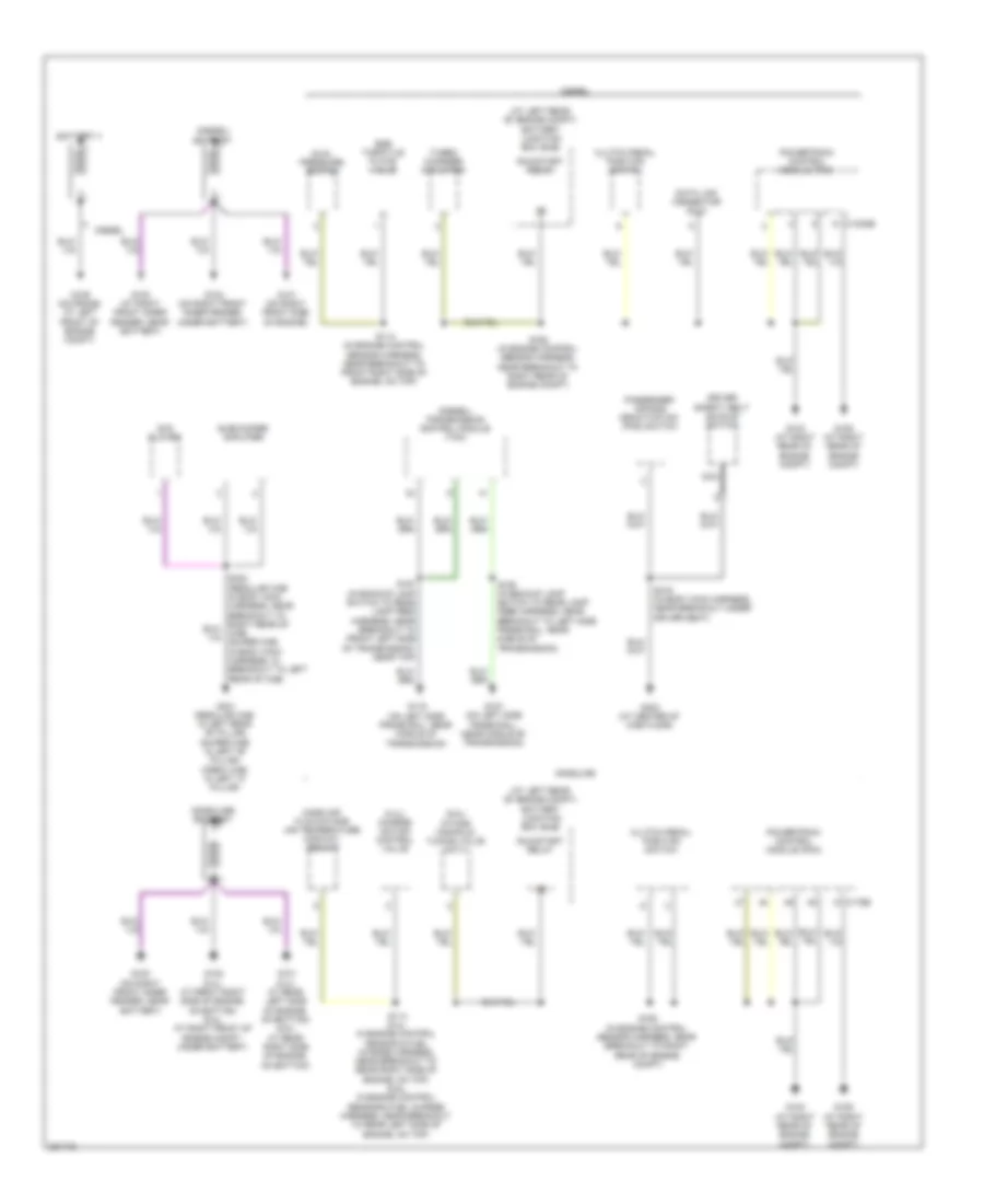 https://portal-diagnostov.com/license.html
Automotive Electricians Portal FZCO
Automotive Electricians Portal FZCO
https://portal-diagnostov.com/license.html
https://portal-diagnostov.com/license.html
Automotive Electricians Portal FZCO
Automotive Electricians Portal FZCOList of elements for Ground Distribution Wiring Diagram (1 of 5) for Ford Cab & Chassis F350 Super Duty 2008:
- (5.4l) charge motion control valve
- (6.8l) intake manifold tuning valve (imtv)
- (at left rear of engine compt) battery junction box (bjb)
- (diesel) battery
- (diesel) transmission control module (tcm)
- (gasoline) battery
- Battery ii
- C1232b
- C175b
- Clutch pedal position switch
- Data link connector (dlc)
- Diesel
- Driver safety belt buckle switch
- Dual pressure switch
- Dvd player
- Egr throttle plate valve
- G100 (at right front inner fender, near battery)
- G100 (on right front inner fender, near battery)
- G101 (5.4l: at rear left side of engine, on bottom) (6.8l: at rear right side of engine, on bottom)
- G101 (on right front side of engine)
- G102 (5.4l: at front right side of engine, on bottom) (6.8l: at right front of engine compt, under battery)
- G102 (on right front inner fender, under battery)
- G103 (at right rear of engine compt)
- G106 (at right rear of engine compt)
- G107 (on left side frame rail, near middle of transmission)
- G109 (on frame, at left front of engine compt)
- G116 (on left side frame rail, near middle of transmission)
- G301 (regular cab: in left rear "b" pillar) (super cab: in left "b" pillar) (crew cab: in left "c" pillar)
- G303 (at center of cab floor)
- Gasoline
- Mass air flow/intake air temperature (maf/iat) sensor
- Nca
- Passenger air bag deactivation (pad) switch
- Powertrain control module (pcm)
- Run/start relay
- S114 (5.4l: in engine control sensor & fuel charge harness, near breakout to rear right side of engine, on top) (6.8l: in engine control sensor & fuel charge harness, near breakout to rear left side of engine, on top)
- S114 (in engine control sensor harness, near breakout to front right side of engine, on top)
- S162 (in engine control sensor harness, near breakout to right rear of engine compt)
- S190 (in backup lamp switch to rear lamp feed harness, near breakout to left side frame rail, near middle of transmission)
- S191 (in backup lamp switch to rear lamp feed harness, near breakout to front left side of transmission, near top)
- S316 (in body main harness, near breakout under driver seat)
- Subwoofer amplifier
- Turbo charger actuator
Ground Distribution Wiring Diagram (2 of 5) for Ford Cab & Chassis F350 Super Duty 2008
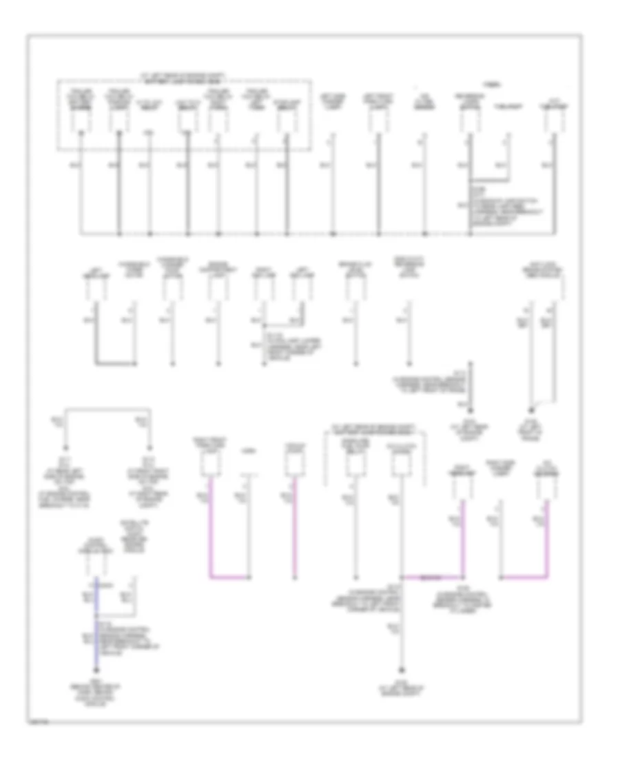 https://portal-diagnostov.com/license.html
Automotive Electricians Portal FZCO
Automotive Electricians Portal FZCO
https://portal-diagnostov.com/license.html
https://portal-diagnostov.com/license.html
Automotive Electricians Portal FZCO
Automotive Electricians Portal FZCOList of elements for Ground Distribution Wiring Diagram (2 of 5) for Ford Cab & Chassis F350 Super Duty 2008:
- (a/t) fuel pump
- (at left rear of engine compt) battery junction box (bjb)
- (gas w/ m/t) reversing lamp switch
- (gasoline) fuel pump relay
- 87a
- A/c clutch diode
- A/c clutch solenoid
- Air filter sensor
- Anti-lock brake system (abs) module
- Audio control module (acm)
- Brake fluid level switch
- C240a
- Diesel
- Engine compartment lamp
- Fuel pump
- G104 (at left rear of engine compt)
- G108 (at left rear of engine compt)
- G111 (5.4l: at rear left side of engine, on top) (6.8l: at engine control fuel charge, near breakout to c115)
- G112 (5.4l: at front right side of engine, on top) (6.8l: at right rear of engine compt)
- G135 (at left front of frame)
- G201 (behind center of dash, behind audio control module)
- Hi to low relay
- Horn
- Left fog lamp
- Left front park/turn lamp
- Left headlamp
- Left side marker lamp
- Low to hi relay
- Reversing lamps switch
- Right fog lamp
- Right front park/turn lamp
- Right headlamp
- Right side marker lamp
- S1119 (in fog lamp jumper harness, near left front corner of vehicle)
- S113 (in engine control sensor harness, near breakout to left front of frame)
- S115 (in engine control sensor harness, near breakout to left front corner of vehicle)
- S119 (in engine control sensor harness, near breakout to left front corner of vehicle)
- S128 (in engine control sensor harness, in breakout to master cylinder)
- S199 (m/t) (in backup lamp switch to rear lamp feed harness, near breakout to left rear of engine compt)
- Satellite digital audio receiver (sdars) module
- Stoplamp relay
- Trailer tow relay battery charge
- Trailer tow relay left turn
- Trailer tow relay parking lamp
- Trailer tow relay right turn
- Vacuum pump
- Windshield washer pump motor
- Windshield wiper motor
Ground Distribution Wiring Diagram (3 of 5) for Ford Cab & Chassis F350 Super Duty 2008
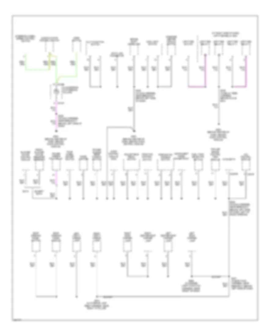 https://portal-diagnostov.com/license.html
Automotive Electricians Portal FZCO
Automotive Electricians Portal FZCO
https://portal-diagnostov.com/license.html
https://portal-diagnostov.com/license.html
Automotive Electricians Portal FZCO
Automotive Electricians Portal FZCOList of elements for Ground Distribution Wiring Diagram (3 of 5) for Ford Cab & Chassis F350 Super Duty 2008:
- (at right side of dash) upfitter relay box
- 4x4 control module
- Adjustable pedal switch
- Audio control module (acm)
- Audio/climate control switch
- Behind left side of dash)
- Blower motor control module
- Brake shift interlock
- C218a
- C218b
- C2357b
- C281b
- Cigar lighter
- Clockspring (in steering column)
- Data link connector
- Eatc
- Except eatc
- Four- wheel driver switch
- Front blower motor resister assembly
- Fuel tank selector switch
- G202 (behind center of dash, behind audio control module)
- G203 (behind center of dash, behind audio control module)
- G204 (behind center of dash, behind audio control module)
- Horn switch
- Hvac-emtc
- Instrument panel power point
- Left center roof marker lamp
- Left roof marker lamp
- Left vanity mirror lamp
- Main light switch
- Massage center module switch
- Multi-function switch
- Parking aid disable switch
- Power mirror fold relay
- Power sliding rear window switch
- Radio opening)
- Right center roof marker lamp
- Right roof marker lamp
- Right vanity mirror lamp
- Roof opening panel module
- Roof opening panel switch
- S235 (in main harness, near breakout behind left side of dash)
- S247 (in body main harness, near breakout behind left side of dash)
- S249 (in relay feed harness, behind glove box)
- S905 (in marker lamp-to-switch harness, near front of roof)
- S910 (in interior lamp feed harness, near right "a" pillar)
- Steering wheel/ speed control switch
- Traction control switch
- Trailer brake control (tbc) module
- Upfitter relay 1
- Upfitter relay 2
- Upfitter relay 3
- Upfitter relay 4
- Upfitter switch
Ground Distribution Wiring Diagram (4 of 5) for Ford Cab & Chassis F350 Super Duty 2008
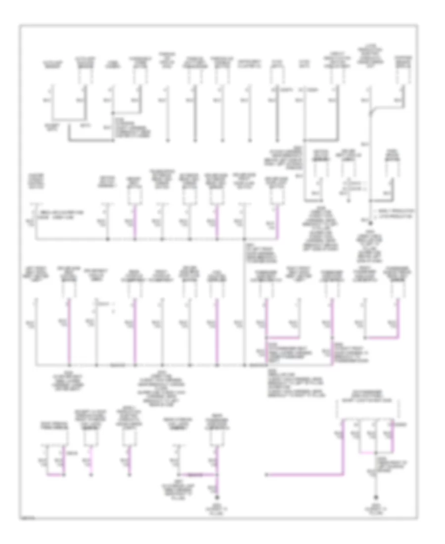 https://portal-diagnostov.com/license.html
Automotive Electricians Portal FZCO
Automotive Electricians Portal FZCO
https://portal-diagnostov.com/license.html
https://portal-diagnostov.com/license.html
Automotive Electricians Portal FZCO
Automotive Electricians Portal FZCOList of elements for Ground Distribution Wiring Diagram (4 of 5) for Ford Cab & Chassis F350 Super Duty 2008:
- (crew cab)
- (early production) electro- chromatic inside mirror unit
- (except w/ roof opening panel) front interior/ map lamps assembly
- (late production) electro- chromatic inside mirror unit
- (on passenger side kick panel) smart junction box (sjb)
- (regular & super cab)
- Autolamp sensor
- Autolamp/ sunload sensor
- C2280d
- C228a
- C2357a
- C341a
- C341b
- C341c
- C921b
- Circuit deactivation ignition module (cdim)
- Compass sensor module
- Driver seat module (dsm)
- Driver side door lock switch
- Driver side exterior rear view mirror
- Driver side front door ajar switch
- Driver side rear door ajar switch
- Driver side seat control switch
- Early production
- Eatc
- Except eatc
- Exterior rear view mirror switch
- Front console power point
- Front passenger side door ajar switch
- G300 (crew cab & regular cab: in left "a" pillar) (super cab: behind left side of dash)
- G302 (in right "a" pillar)
- G304 (in right "a" pillar)
- High mounted stoplamp
- Hvac- eatc
- Hvac- emtc
- Instrument cluster (ic)
- Keypad switch assembly
- Late production
- Left front seat back rest heater mat
- Master window control switch
- Memory seat switch
- Park brake switch
- Parking aid disable switch
- Parking aid module (pam)
- Passenger side door lock switch
- Passenger side exterior rear view mirror
- Passenger side seat control switch
- Passive anti-theft transceiver
- Rear console power point
- Rear interior/ map lamps assembly
- Rear passenger side door ajar switch
- Right front seat back rest heater mat
- Roof opening panel module
- S185 (in engine compt harness, in breakout near master cylinder)
- S224 (in main harness, near breakout behind left side of dash, left of radio opening)
- S308 (regular cab: in body main harness, near breakout to left "b" pillar) (super cab: in body main harness, near breakout to right "a" pillar)
- S323 (crew cab: in body main harness, near breakout across floor) (super cab: in body main harness, near breakout to left rear of cab)
- S326 (crew cab: in body main harness, near breakout to left "a" pillar) (super cab: in body main harness, near breakout behind left side of dash)
- S338 (in driver seat feed jumper harness, under driver seat)
- S339 (in passenger seat feed jumper harness, under passenger seat)
- S501 (in left front door harness, near breakout to driver door)
- S639 (in right front door harness, in breakout to passenger door)
- S907 (in interior lamp feed harness, near right "a" pillar)
- Telescoping exterior rear view mirror switch
- Video camera
- Windshield wiper motor
Ground Distribution Wiring Diagram (5 of 5) for Ford Cab & Chassis F350 Super Duty 2008
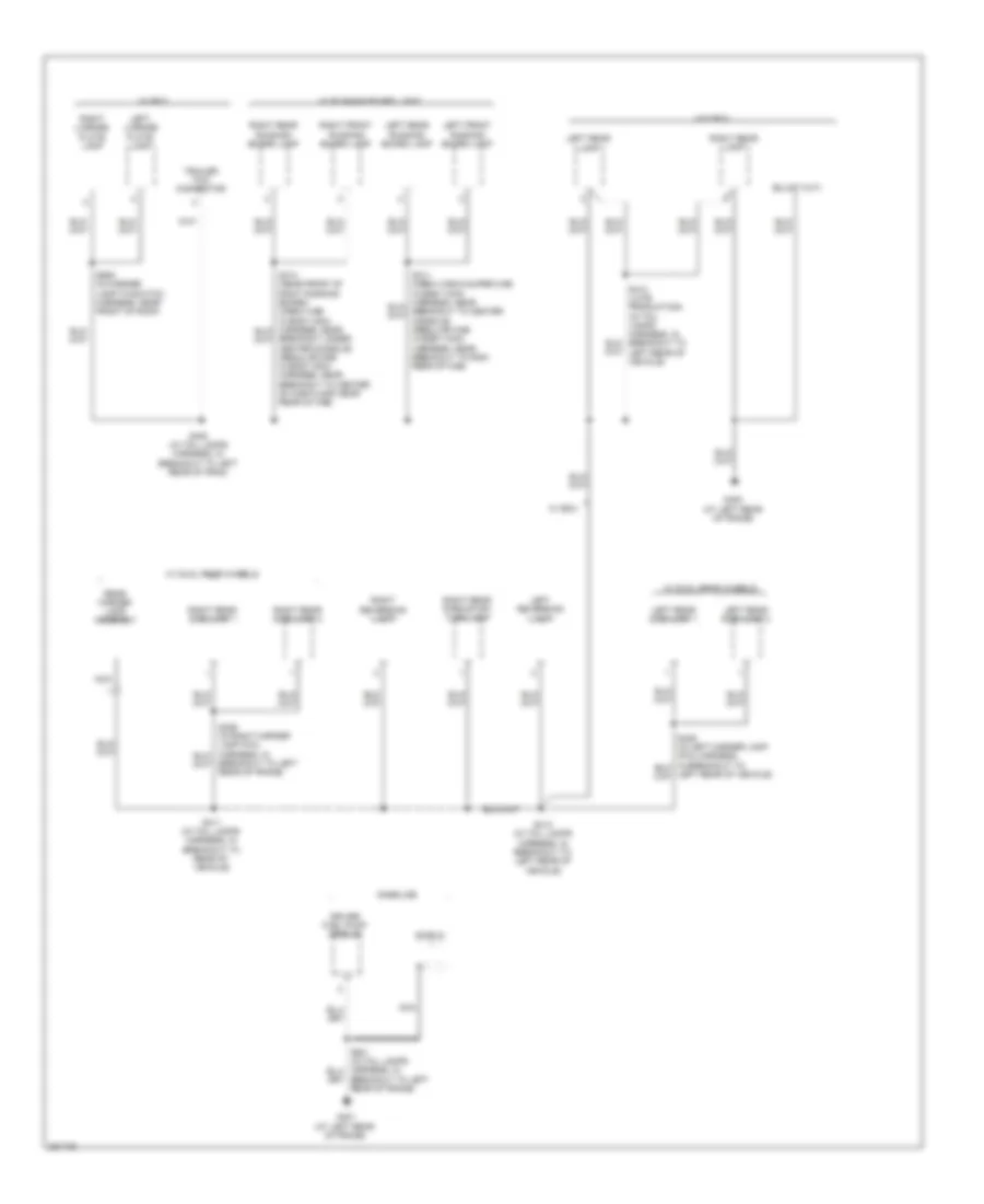 https://portal-diagnostov.com/license.html
Automotive Electricians Portal FZCO
Automotive Electricians Portal FZCO
https://portal-diagnostov.com/license.html
https://portal-diagnostov.com/license.html
Automotive Electricians Portal FZCO
Automotive Electricians Portal FZCOList of elements for Ground Distribution Wiring Diagram (5 of 5) for Ford Cab & Chassis F350 Super Duty 2008:
- Breakout to left rear of frame)
- Breakout under center console) (regular cab: in body main harness, near breakout to center of cab floor, near rear of cab)
- Driver fuel pump module
- G400 (at left rear of frame)
- G401 (at left rear of frame)
- Gasoline
- Left front running board lamp
- Left license plate lamp
- Left rear lamp
- Left rear running board lamp
- Left rear side lamp 1
- Left rear side lamp 2
- Left reversing lamp
- Nca
- Rear marker lamp assembly
- Right front running board lamp
- Right license plate lamp
- Right rear lamp
- Right rear park/stop/ turn lamp
- Right rear running board lamp
- Right rear side lamp 1
- Right rear side lamp 2
- Right reversing lamp
- S400 (in tail lamps harness, in breakout to left rear of fram)
- S411 (in tail lamps harness, in breakout to rear of vehicle)
- S413 (in tail lamps harness, in breakout to left rear of vehicle)
- S905 (in marker lamp-to-switch harness, near front of roof)
- Shield
- Trailer tow connector
- W/ box
- W/ dual rear wheels
- W/ running board light
- W/o box
HEADLIGHTS
Headlights Wiring Diagram for Ford Cab & Chassis F350 Super Duty 2008
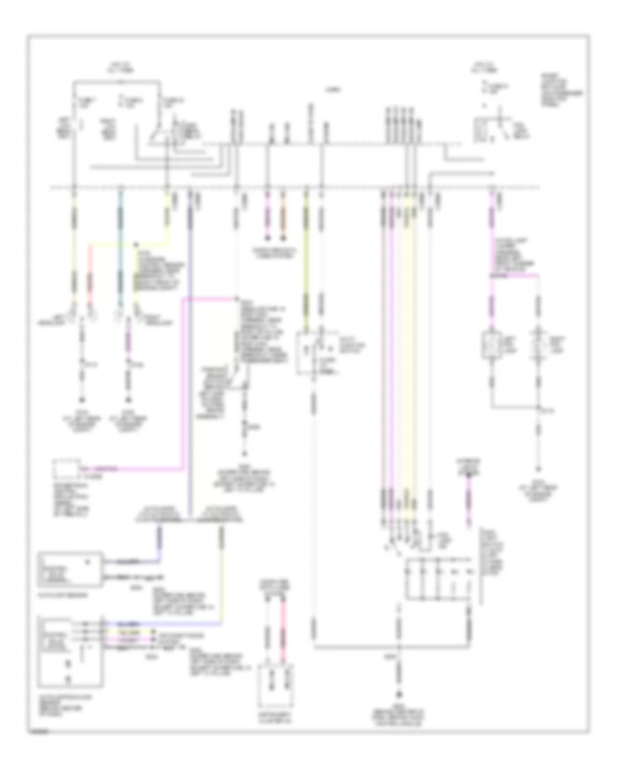 https://portal-diagnostov.com/license.html
Automotive Electricians Portal FZCO
Automotive Electricians Portal FZCO
https://portal-diagnostov.com/license.html
https://portal-diagnostov.com/license.html
Automotive Electricians Portal FZCO
Automotive Electricians Portal FZCOList of elements for Headlights Wiring Diagram for Ford Cab & Chassis F350 Super Duty 2008:
- (in fog lamp jumper harness, near left front corner of vehicle) s142
- Air conditioning system
- Autolamp in
- Autolamp on
- Autolamp sensor
- Autolamp/sunload sensor (behind center of dash)
- Autolamps w/ automatic climate control
- Autolamps w/o automatic climate control
- C1232b
- C2280a
- C2280b
- C2280c
- C2280e
- Computer data lines system
- Control solid state
- Flash to pass
- Fog lamp
- Fog lamp ind
- Fog lamp relay
- Ftp
- Fuse 21 15a
- Fuse 23 15a
- Fuse 7 10a
- Fuse 8 10a
- G104 (at left rear of engine compt)
- G108 (at left rear of engine compt)
- G203 (behind center of dash, behind audio control module)
- G300 (super cab: behind left side of dash) (except super cab: in left "a" pillar)
- Headlamp off
- Headlamp on
- Hi beam
- High beam relay
- Hot at all times
- Instrument cluster (ic)
- Interior lights system
- Left fog lamp
- Left headlamp
- Left low beam (fet)
- Main light switch 1) auto 2) off 3) park 4) head 5) fog
- Micro
- Ms can+
- Ms can-
- Multi- function switch
- Park brake
- Parking brake switch (behind left side of dash, on park brake assembly)
- Parklamp on
- Powertrain control module (pcm) (diesel) (at left side of firewall)
- Right fog lamp
- Right headlamp
- Right low beam (fet)
- S113
- S119
- S122 (in engine control sensor harness, near breakout to right front of engine compt)
- S128
- S224
- S235
- S304 (regular cab: in body main harness, near breakout to right "b" pillar) (super cab: in body main harness, near breakout under passenger seat)
- S326
- Smart junction box (sjb) (on passenger side kick panel)
HORN
Horn Wiring Diagram for Ford Cab & Chassis F350 Super Duty 2008
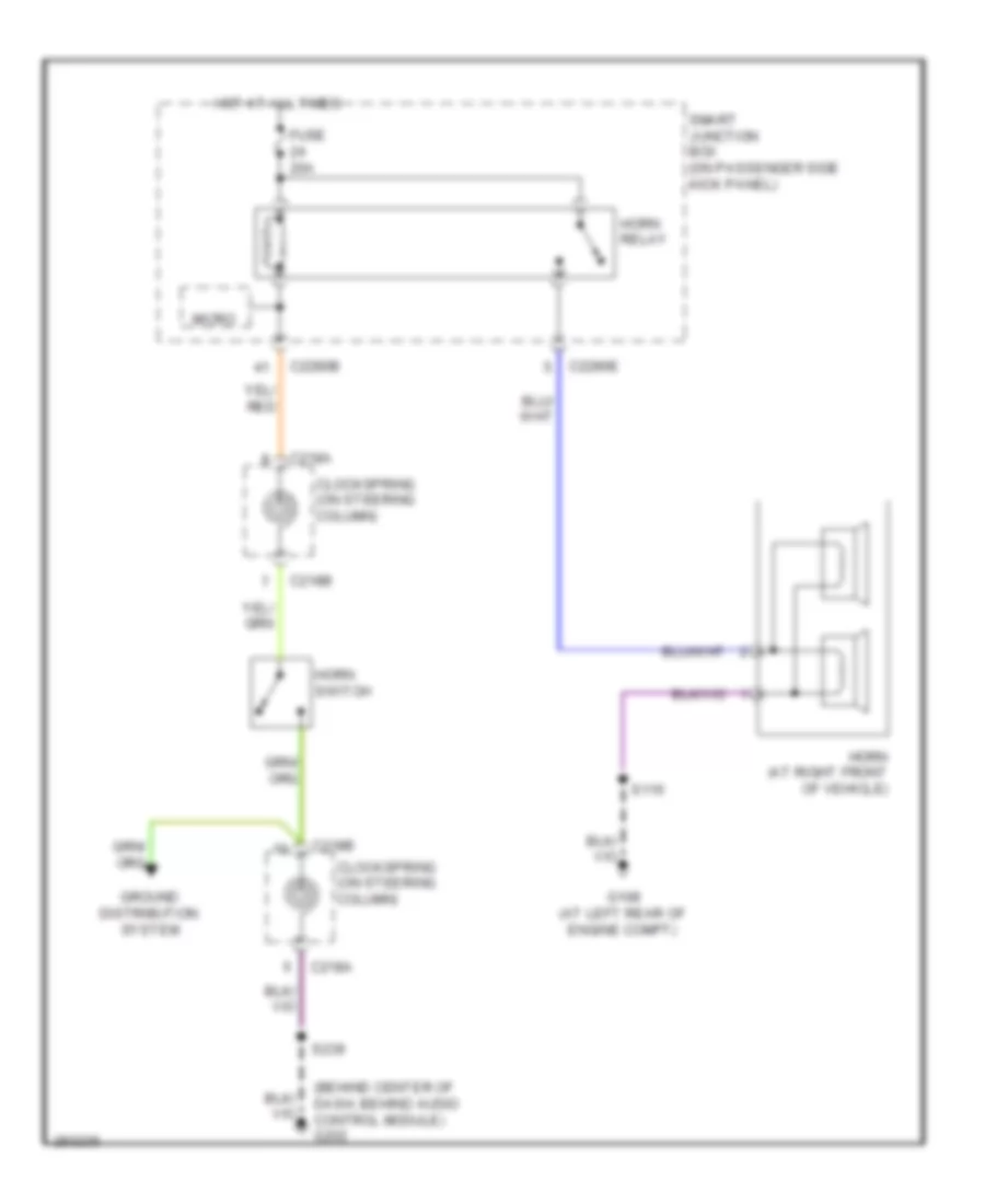 https://portal-diagnostov.com/license.html
Automotive Electricians Portal FZCO
Automotive Electricians Portal FZCO
https://portal-diagnostov.com/license.html
https://portal-diagnostov.com/license.html
Automotive Electricians Portal FZCO
Automotive Electricians Portal FZCOList of elements for Horn Wiring Diagram for Ford Cab & Chassis F350 Super Duty 2008:
- (behind center of dash, behind audio control module) g202
- C218a
- C218b
- C2280b
- C2280e
- Clockspring (on steering column)
- Fuse 20a
- G108 (at left rear of engine compt)
- Ground distribution system
- Horn (at right front of vehicle)
- Horn relay
- Horn switch
- Hot at all times
- Micro
- S115
- S239
- Smart junction box (on passenger side kick panel)
INSTRUMENT CLUSTER
Instrument Cluster Wiring Diagram (1 of 2) for Ford Cab & Chassis F350 Super Duty 2008
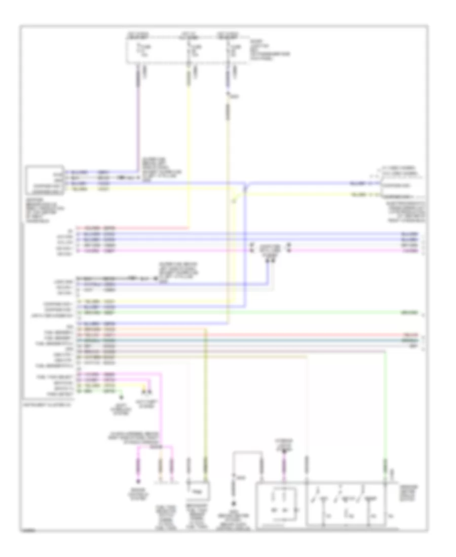 https://portal-diagnostov.com/license.html
Automotive Electricians Portal FZCO
Automotive Electricians Portal FZCO
https://portal-diagnostov.com/license.html
https://portal-diagnostov.com/license.html
Automotive Electricians Portal FZCO
Automotive Electricians Portal FZCOList of elements for Instrument Cluster Wiring Diagram (1 of 2) for Ford Cab & Chassis F350 Super Duty 2008:
- (in main harness, behind right side of dash, right of radio opening)
- (super cab: behind left side of dash) (except super cab: in left "a" pillar) g300
- 4x4 high
- 4x4 low
- Air filter minder sw
- Anti-theft system
- C218a
- C2280a
- C2280b
- Cbp31
- Cbp36
- Ccf06
- Ccf22
- Ce927
- Ce929
- Cet52
- Cmc24
- Cmc29
- Compass mod +
- Compass mod -
- Compass sensor module (early production) (at top center of front windshield)
- Computer data lines system
- Electrochromatic inside mirror unit (late production) (at center of front windshield)
- Engine controls system
- Epats rx
- Epats tx
- Fuel sender 1
- Fuel sender 2
- Fuel sender rtn 2
- Fuel tank select
- Fuel tank selector switch (diesel w/ dual fuel tank)
- Fuse 10a
- Fuse 5a
- G203 (behind center of dash, behind audio control module)
- Gd133
- Gnd
- Hot at all times
- Hot in run or start
- Hs can +
- Hs can -
- Info
- Instrument cluster (ic)
- Interior lights system
- Logic gnd
- Message center module switch
- Ms can +
- Ms can -
- Msg ctr +
- Msg ctr -
- Ops
- Park detect
- Pwr
- R/s
- Reset
- Rmc27
- Rmc32
- Rmc33
- S223
- S224
- S235
- S245
- S326
- Sbp26
- Secondary fuel tank sensor (diesel w/ dual fuel tank)
- Setup
- Shift interlock system
- Smart junction box (on passenger side kick panel)
- Vdb04
- Vdb05
- Vdb06
- Vdb07
- Vmc11
- Vmc23
- Vmc30
- Vmc31
- Vrt23
- Vrt24
- W/ video camera
- W/o video camera
Instrument Cluster Wiring Diagram (2 of 2) for Ford Cab & Chassis F350 Super Duty 2008
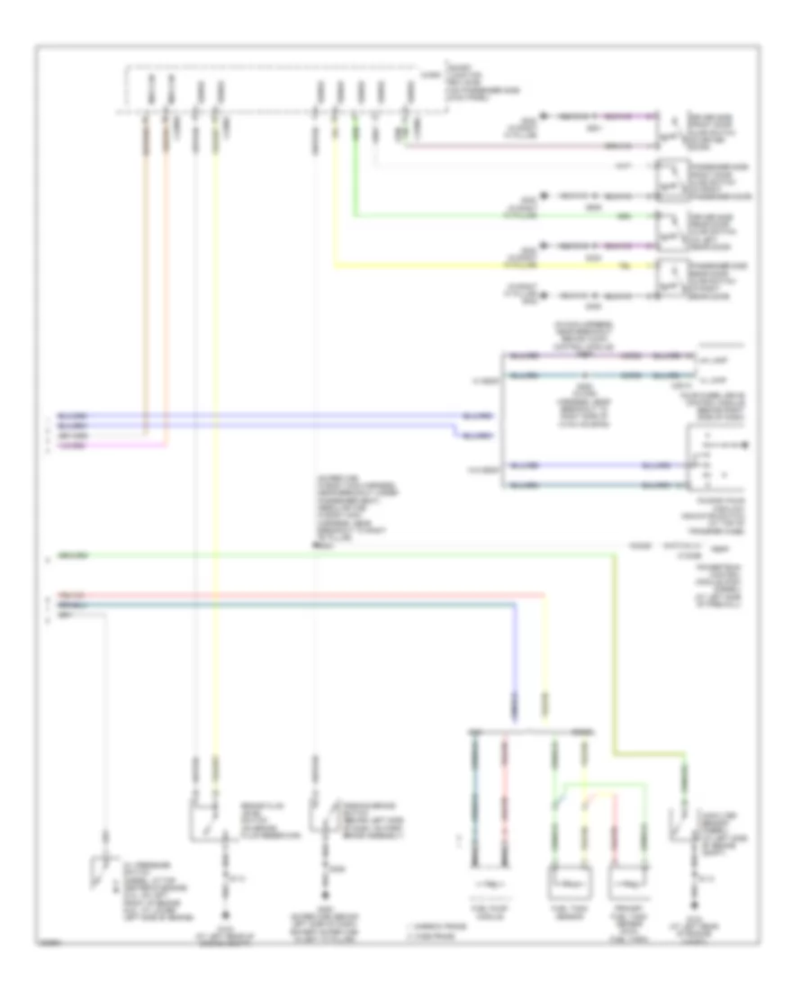 https://portal-diagnostov.com/license.html
Automotive Electricians Portal FZCO
Automotive Electricians Portal FZCO
https://portal-diagnostov.com/license.html
https://portal-diagnostov.com/license.html
Automotive Electricians Portal FZCO
Automotive Electricians Portal FZCOList of elements for Instrument Cluster Wiring Diagram (2 of 2) for Ford Cab & Chassis F350 Super Duty 2008:
- (in main harness, near breakout behind audio control module) s209
- (in right "a" pillar) g302
- (super cab: in body main harness, near breakout under passenger seat) (regular cab: in body main harness, near breakout to right "b" pillar) s304
- 4h lamp
- 4l lmap
- Air filter sensor (diesel) (at left side of engine compt)
- Ajar
- Brake fluid level switch (on brake fluid reservoir)
- C1232b
- C2280b
- C2280c
- C2280f
- C281a
- Ccf06
- Ccf22
- Cmc25
- Diesel
- Driver side front door ajar switch (in driver door)
- Driver side rear door ajar switch (in left rear door)
- Four-by-four high/low indicator switch (at top of transfer case)
- Four-wheel drive control module (behind right side of dash)
- Fuel pump module
- Fuel tank sensor
- G104 (at left rear of engine compt)
- G300 (super cab: behind left side of dash) (except super cab: in left "a" pillar)
- G302 (in right "a" pillar)
- Gas
- Med can
- Micro
- Narrow frame
- Nca
- Oil pressure switch (diesel: at top center of engine) (5.4l: on left front of engine (6.8l: at lower left side of engine)
- Parking brake switch (behind left side of dash, on park brake assembly)
- Passenger side front door ajar switch (in front passenger door)
- Passenger side rear door ajar switch (in right rear door)
- Pbpp
- Powertrain control module (pcm) (diesel) (at left side of firewall)
- Primary fuel tank sensor (dual fuel tank)
- S113
- S205 (in main harness, near breakout to right side of hvac housing)
- S308
- S323
- S326
- S501
- S639
- Sense
- Smart junction box (sjb) (on passenger side kick panel)
- W/ esof
- W/o esof
- Wide frame
INTERIOR LIGHTS
Courtesy Lamps Wiring Diagram for Ford Cab & Chassis F350 Super Duty 2008
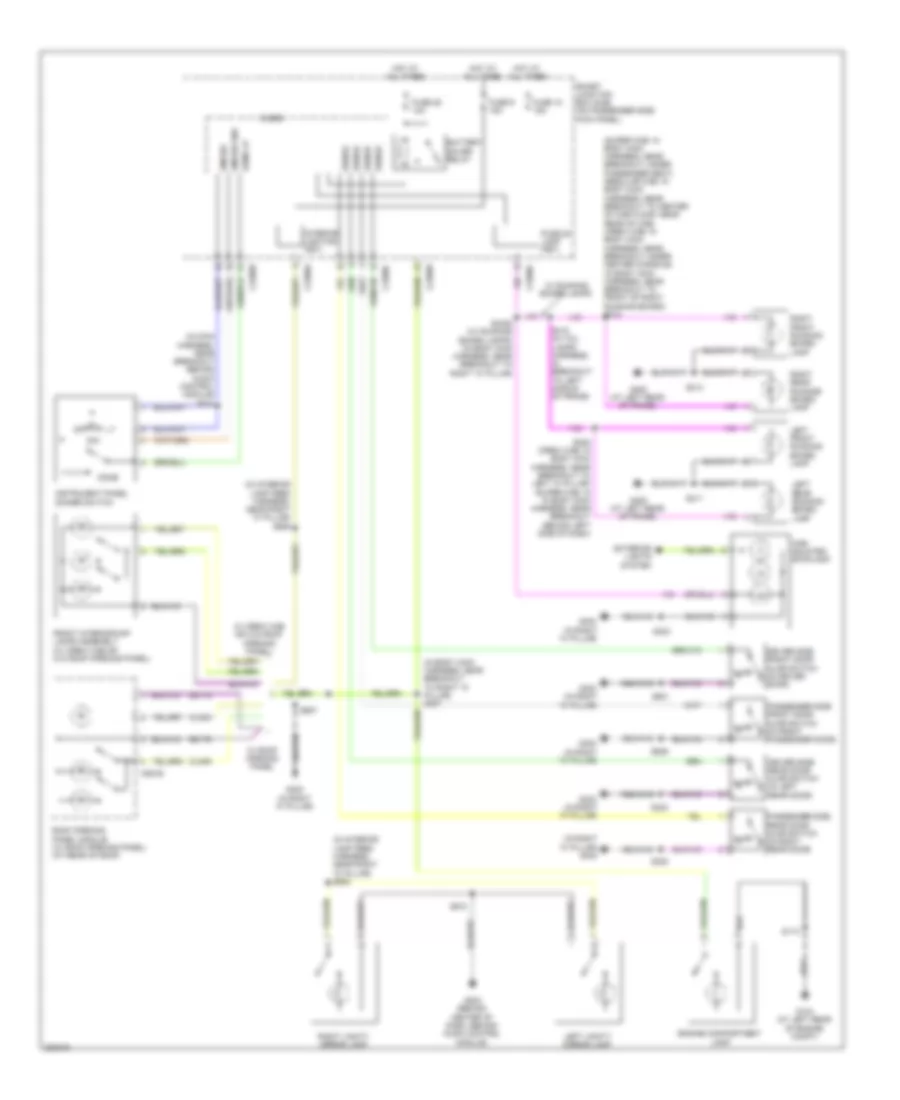 https://portal-diagnostov.com/license.html
Automotive Electricians Portal FZCO
Automotive Electricians Portal FZCO
https://portal-diagnostov.com/license.html
https://portal-diagnostov.com/license.html
Automotive Electricians Portal FZCO
Automotive Electricians Portal FZCOList of elements for Courtesy Lamps Wiring Diagram for Ford Cab & Chassis F350 Super Duty 2008:
- (in body main harness, near breakout to right "a" pillar) s307
- (in interior lamp feed harness, near right "a" pillar) s908
- (in interior lamp feed harness, near right "a" pillar) s909
- (in main harness, near breakout behind audio control module) s214
- (in right "a" pillar) g302
- (super cab: in body main harness, near breakout under passenger seat) (regular cab: in body main harness, near breakout to center of cab floor, near rear of cab) (crew cab: in body main harness, near breakout under center console) (in body main harness, near breakout to front of right running board) s312
- Ajar
- Battery saver relay
- C2280a
- C2280b
- C2280c
- C2280d
- C921b
- Cln03
- Cln09
- Dim
- Dim sw
- Dim sw gnd
- Dome
- Dome lp
- Driver side front door ajar switch (in driver door)
- Driver side rear door ajar switch (in left rear door)
- Engine compartment lamp
- Exterior lights system
- Front interior/map lamps assembly (w/ crew cab or w/o roof opening panel)
- Fuse 10 15a
- Fuse 25 10a
- Fuse 9 15a
- G104 (at left rear of engine compt)
- G203 (behind center of dash, behind audio control module)
- G302 (in right "a" pillar)
- G400 (at left rear of frame)
- Gd179
- High mounted stoplamp
- Hot at all times
- Instrument panel dimmer switch
- Interior lighting (fet)
- Left front running board lamp
- Left rear running board lamp
- Left vanity mirror lamp
- Micro
- Passenger side front door ajar switch (in front passenger door)
- Passenger side rear door ajar switch (in right rear door)
- Puddle lamp (fet)
- Right front running board lamp
- Right rear running board lamp
- Right vanity mirror lamp
- Roof opening panel module (w/ roof opening panel) (at rear of roof)
- S113
- S308
- S311
- S313
- S323
- S328 (crew cab: in body main harness, near breakout to left "a" pillar) (super cab: in in body main harness, near breakout behind left side of dash)
- S3325 (w/ running board lamps) (in body main harness, near breakout to right "a" pillar)
- S410 (in tail lamps harness, in breakout to left middle of frame)
- S501
- S639
- S907
- S910
- Sense
- Smart junction box (sjb) (on passenger side kick panel)
- W/ crew cab or w/o roof opening panel)
- W/ roof opening panel
- W/ running board lamps
Instrument Illumination Wiring Diagram for Ford Cab & Chassis F350 Super Duty 2008
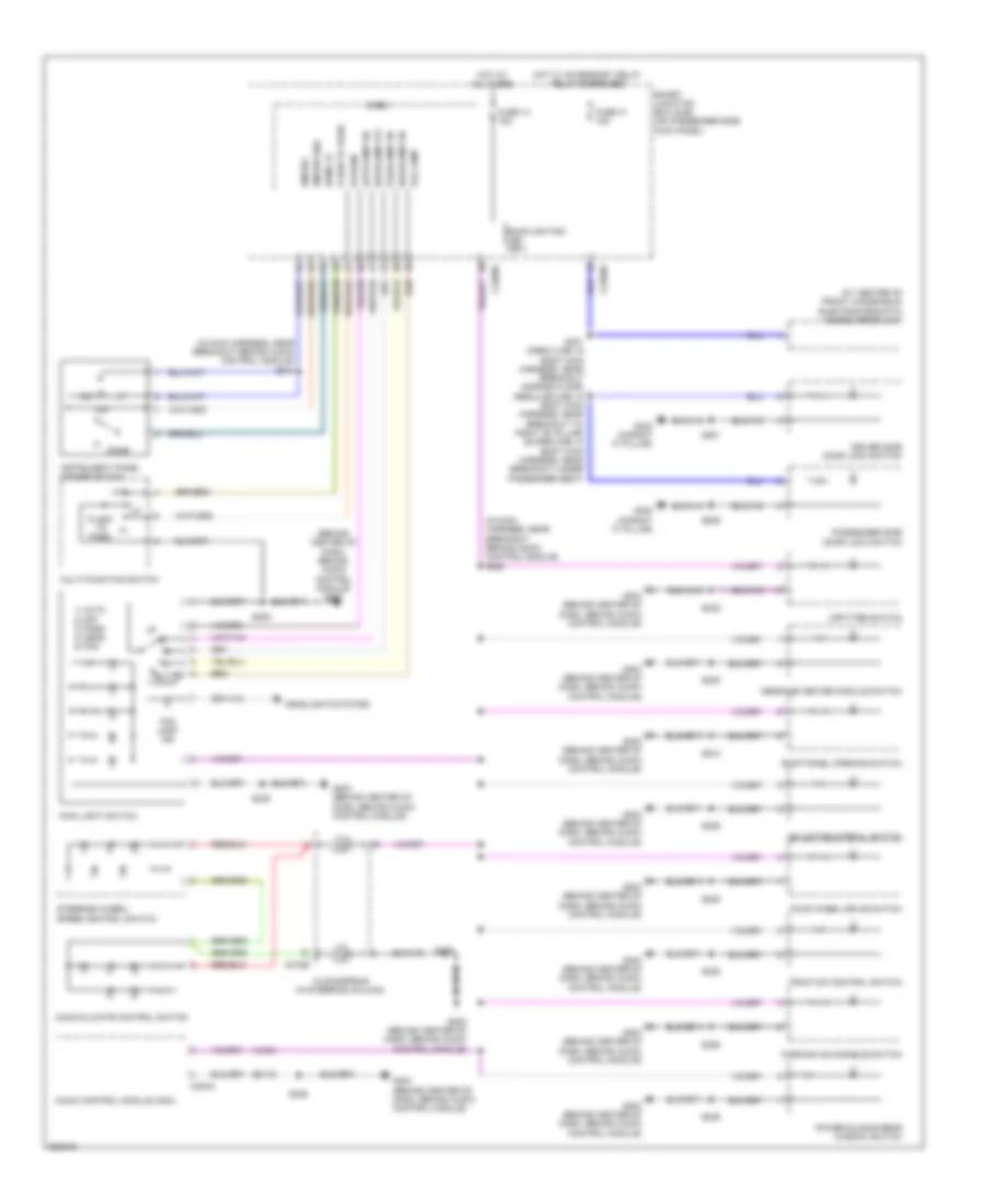 https://portal-diagnostov.com/license.html
Automotive Electricians Portal FZCO
Automotive Electricians Portal FZCO
https://portal-diagnostov.com/license.html
https://portal-diagnostov.com/license.html
Automotive Electricians Portal FZCO
Automotive Electricians Portal FZCOList of elements for Instrument Illumination Wiring Diagram for Ford Cab & Chassis F350 Super Duty 2008:
- (at center of front windshield) electrochromatic inside mirror unit
- (behind center of dash, behind audio control module) g203
- (in main harness, near breakout behind audio control module) s214
- (in main harness, near breakout behind audio control module) s220
- 1) auto 2) off 3) park 4) head 5) fog
- Adjustable pedal switch
- Audio control module (acm)
- Audio/climate control switch
- Autolamp on
- Backlighting led (fet)
- C218b
- C2280b
- C2280d
- C240a
- Clockspring (in steering column)
- Dim
- Dim sw
- Dim sw gnd
- Dome
- Dome lp
- Driver side door lock switch
- Flash to pass
- Fog lamp
- Fog lamp ind
- Four wheel drive switch
- Ftp
- Fuse 10 15a
- Fuse 41 15a
- G202 (behind center of dash, behind audio control module)
- G203 (behind center of dash, behind audio control module)
- G204 (behind center of dash, behind audio control module)
- G302 (in right "a" pillar)
- Gd115
- Headlamp off
- Headlamp on
- Headlights system
- Hi beam
- Hot at all times
- Hot w/ accessory delay relay energized
- Instrument panel dimmer switch
- Main light switch
- Message center module switch
- Micro
- Multi-function switch
- Parking aid disable switch
- Parklamp on
- Passenger side door lock switch
- Power sliding rear window switch
- Roof panel opening switch
- S225
- S235
- S239
- S301 (crew cab: in body main harness, near breakout across floor) (regular cab: in body main harness, near breakout to right "b" pillar) (super cab: in body main harness, near breakout under passenger seat)
- S501
- S639
- S910
- Smart junction box (sjb) (on passenger side kick panel)
- Steering wheel/ speed control switch
- Traction control switch
- Upfitter switch
- Vln04
MEMORY SYSTEMS
Adjustable Pedal Wiring Diagram for Ford Cab & Chassis F350 Super Duty 2008
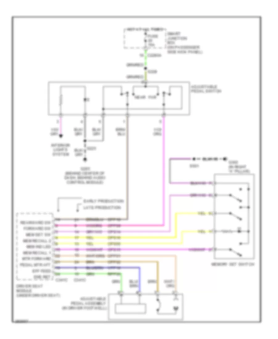 https://portal-diagnostov.com/license.html
Automotive Electricians Portal FZCO
Automotive Electricians Portal FZCO
https://portal-diagnostov.com/license.html
https://portal-diagnostov.com/license.html
Automotive Electricians Portal FZCO
Automotive Electricians Portal FZCOList of elements for Adjustable Pedal Wiring Diagram for Ford Cab & Chassis F350 Super Duty 2008:
- Adjustable pedal assembly (in driver footwell)
- Adjustable pedal switch
- C2280a
- C341c
- Cpp01
- Cpp02
- Cpp09
- Cpp10
- Cps14
- Cps15
- Cps16
- Cps55
- Driver seat module (under driver seat)
- Early production
- Eff feed
- Far
- Forward sw
- Fuse 15a
- G203 (behind center of dash, behind audio control module)
- G302 (in right "a" pillar)
- Hot at all times
- Interior lights system
- Late production
- Mem ind led
- Mem recall 1
- Mem recall 2
- Mem set sw
- Memory set switch
- Mtr forward
- Near
- Pedal mtr aft
- Rearward sw
- Rpp06
- S228
- S501
- Smart junction box (on passenger side kick panel)
- Sns ret
- Vpp16
Driver"s Memory Seat Wiring Diagram, Early Production for Ford Cab & Chassis F350 Super Duty 2008
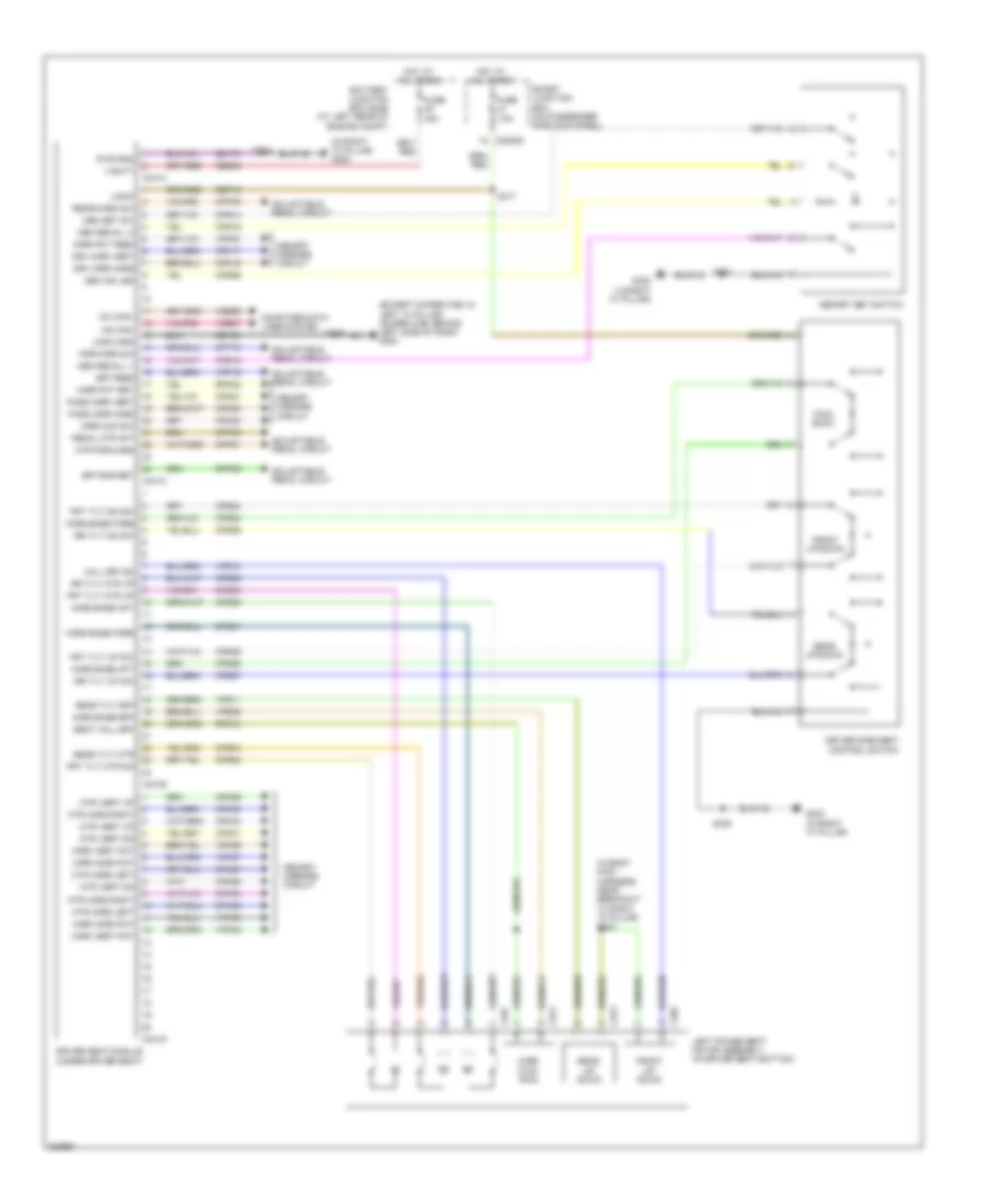 https://portal-diagnostov.com/license.html
Automotive Electricians Portal FZCO
Automotive Electricians Portal FZCO
https://portal-diagnostov.com/license.html
https://portal-diagnostov.com/license.html
Automotive Electricians Portal FZCO
Automotive Electricians Portal FZCOList of elements for Driver"s Memory Seat Wiring Diagram, Early Production for Ford Cab & Chassis F350 Super Duty 2008:
- (except super cab: in left "a" pillar) (super cab: behind left side of dash) g300
- (in body main harness, near breakout to right "a" pillar) s334
- (in right "a" pillar) g302
- Adjustable pedal circuit
- Battery junction box (bjb) (at left rear of engine compt)
- C2280d
- C341a
- C341b
- C341c
- C341d
- C357
- C372
- C373
- C383
- Computer data lines system
- Cpm16
- Cpm17
- Cpm20
- Cpm21
- Cpm23
- Cpm26
- Cpm27
- Cpm28
- Cpm29
- Cpm31
- Cpm32
- Cpm33
- Cpm34
- Cpp01
- Cpp02
- Cpp09
- Cpp10
- Cps01
- Cps02
- Cps03
- Cps04
- Cps05
- Cps06
- Cps14
- Cps15
- Cps16
- Cps23
- Cps24
- Cps25
- Cps26
- Cps27
- Cps28
- Cps55
- Driver seat module (under driver seat)
- Driver side seat control switch
- Drv mirr horz
- Drv mirr vert
- Eff feed
- Eff sns ret
- Forward sw
- Front up/ down
- Front up/down
- Frt tilt dn sw
- Frt tilt mtr dn
- Frt tilt mtr up
- Frt tilt up sw
- Fuse 30a
- Fuse 7.5a
- Fwd/ back
- G302 (in right "a" pillar)
- Gd133
- Gd179
- Hall eff sn
- Horz base aft
- Horz base eff
- Horz base fore
- Horz fwd/ rwd
- Hot at all times
- Left power seat motor assembly (in driver seat bottom)
- Logic
- Logic gnd
- Lpm30
- Mc can+
- Mem ind led
- Mem recall 1
- Mem recall 2
- Mem set sw
- Memory mirrors circuit
- Memory set switch
- Mirr com sw
- Mirr horz pot
- Mirr pot feed
- Mirr pot ret
- Mirr vert pot
- Ms can-
- Mtr forward
- Mtr horz left
- Mtr horz right
- Mtr vert dn
- Mtr vert up
- Pass mirr horz
- Pass mirr vert
- Pedal mtr aft
- Pwr gnd
- Rear tilt eff
- Rear tilt mtr
- Rear up/ down
- Rear up/down
- Rearward sw
- Rpm30
- Rpp06
- Rps13
- Rr tilt dn sw
- Rr tilt mtr up
- Rr tilt up sw
- S317
- S326
- S338
- S501
- Sbb45
- Sbp12
- Seat hall eff
- Smart junction box (on passenger side kick panel)
- V batt
- Vdb06
- Vdb07
- Vpm35
- Vpm36
- Vpm37
- Vpm38
- Vpp16
- Vps09
- Vps10
- Vps11
Driver"s Memory Seat Wiring Diagram, Late Production for Ford Cab & Chassis F350 Super Duty 2008
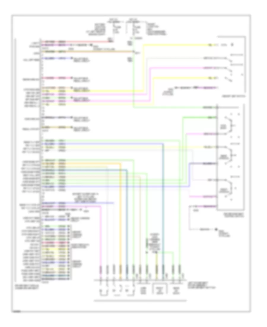 https://portal-diagnostov.com/license.html
Automotive Electricians Portal FZCO
Automotive Electricians Portal FZCO
https://portal-diagnostov.com/license.html
https://portal-diagnostov.com/license.html
Automotive Electricians Portal FZCO
Automotive Electricians Portal FZCOList of elements for Driver"s Memory Seat Wiring Diagram, Late Production for Ford Cab & Chassis F350 Super Duty 2008:
- (except super cab: in left "a" pillar) (super cab: behind left side of dash)
- (in body main harness, near breakout to right "a" pillar) s334
- Adjustable pedal circuit
- Battery junction box (bjb) (at left rear of engine compt)
- C2280d
- C341a
- C341b
- C341c
- C341d
- C357
- C372
- C373
- C383
- Computer data lines system
- Cpm03
- Cpm06
- Cpm16
- Cpm17
- Cpm20
- Cpm21
- Cpm23
- Cpm28
- Cpm29
- Cpm33
- Cpm34
- Cpp01
- Cpp02
- Cpp09
- Cpp10
- Cps01
- Cps02
- Cps03
- Cps04
- Cps05
- Cps06
- Cps14
- Cps15
- Cps16
- Cps23
- Cps24
- Cps25
- Cps26
- Cps27
- Cps28
- Cps55
- Driver seat module (under driver seat)
- Driver side seat control switch
- Drv mirr horz
- Drv mirr vert
- Eff sns ret
- Forward sw
- Front up/ down
- Front up/down
- Frt tilt dn sw
- Frt tilt eff
- Frt tilt mtr dn
- Frt tilt mtr up
- Frt tilt up sw
- Fuse 30a
- Fuse 7.5a
- Fwd/ back
- G300
- G302 (in right "a" pillar)
- Gd133
- Gd179
- Hall eff feed
- Horz base aft
- Horz base eff
- Horz base fore
- Horz fwd/ rwd
- Hot at all times
- Left power seat motor assembly (in driver seat bottom)
- Logic
- Logic gnd
- Lpm30
- Mem ind led
- Mem recall 1
- Mem recall 2
- Mem set sw
- Memory mirrors circuit
- Memory set switch
- Mirr com sw
- Mirr horz pot
- Mirr pot feed
- Mirr pot ret
- Mirr vert pot
- Ms can +
- Ms can -
- Mtr forward
- Mtr horz right
- Mtr ver up
- Mtr vert dn
- Pass mirr horz
- Pass mirr vert
- Pedal mtr aft
- Pwr gnd
- Rear tilt eff
- Rear tilt mtr up
- Rear up/ down
- Rear up/down
- Rearward sw
- Rpm30
- Rpp06
- Rps13
- Rr tilt dn sw
- Rr tilt mtr dn
- Rr tilt up sw
- S317
- S326
- S338
- S501
- Sbb45
- Sbp12
- Seat hall eff
- Smart junction box (on passenger side kick panel)
- V batt
- Vdb06
- Vdb07
- Vpm35
- Vpm36
- Vpm37
- Vpm38
- Vpp16
- Vps09
- Vps10
- Vps11
Memory Mirrors Wiring Diagram, Early Production (1 of 2) for Ford Cab & Chassis F350 Super Duty 2008
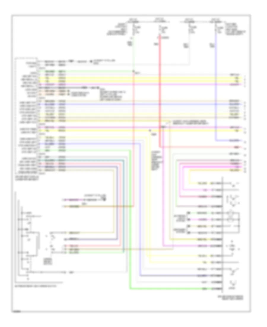 https://portal-diagnostov.com/license.html
Automotive Electricians Portal FZCO
Automotive Electricians Portal FZCO
https://portal-diagnostov.com/license.html
https://portal-diagnostov.com/license.html
Automotive Electricians Portal FZCO
Automotive Electricians Portal FZCOList of elements for Memory Mirrors Wiring Diagram, Early Production (1 of 2) for Ford Cab & Chassis F350 Super Duty 2008:
- (in body main harness, near breakout under driver seat)
- (in right "a" pillar) g302
- Battery junction box (bjb) (at left rear of engine compt)
- C2280d
- C341a
- C341c
- C341d
- Computer data lines system
- Cpm16
- Cpm17
- Cpm20
- Cpm21
- Cpm23
- Cpm26
- Cpm27
- Cpm28
- Cpm29
- Cpm31
- Cpm32
- Cpm33
- Cpm34
- Cps14
- Cps15
- Cps16
- Cps55
- Defogger system
- Driver seat module (under driver seat)
- Driver side exterior rear view mirror
- Drv mirr horz
- Drv mirr vert
- Exterior lights system
- Exterior rear view mirror switch
- Fuse 10a
- Fuse 15a
- Fuse 30a
- Fuse 7.5a
- G300 (except super cab: in left "a" pillar) (super cab: behind left side of dash)
- Gd133
- Gd179
- Hot at all times
- L/r
- Logic
- Logic gnd
- Lpm30
- Mc can+
- Mem ind led
- Mem recall 1
- Mem recall 2
- Mem set sw
- Mirr com sw
- Mirr horz pot
- Mirr pot feed
- Mirr pot ret
- Mirr vert pot
- Mirror select switch
- Ms can-
- Mtr hor right
- Mtr horz left
- Mtr horz right
- Mtr vert dn
- Mtr vert up
- Nca
- Pass mirr horz
- Pass mirr vert
- Pwr gnd
- Red
- Rpm30
- S317
- S318
- S326
- S336
- S338
- S501
- Sbb45
- Sbp12
- Smart junction box (on passenger side kick panel)
- Up/dn
- V batt
- Vdb06
- Vdb07
- Vpm35
- Vpm36
- Vpm37
- Vpm38
Memory Mirrors Wiring Diagram, Early Production (2 of 2) for Ford Cab & Chassis F350 Super Duty 2008
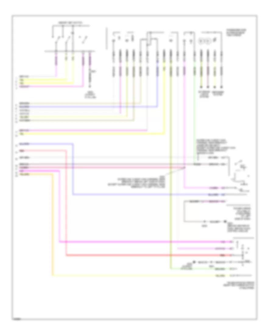 https://portal-diagnostov.com/license.html
Automotive Electricians Portal FZCO
Automotive Electricians Portal FZCO
https://portal-diagnostov.com/license.html
https://portal-diagnostov.com/license.html
Automotive Electricians Portal FZCO
Automotive Electricians Portal FZCOList of elements for Memory Mirrors Wiring Diagram, Early Production (2 of 2) for Ford Cab & Chassis F350 Super Duty 2008:
- (super cab: in body main harness, near breakout under driver seat) (except super cab: in body main harness, near breakout across floor)
- Defogger system
- Dn/up
- Exterior lights system
- G203 (behind center of dash, behind audio control module)
- G302 (in right "a" pillar)
- L/r
- Memory set switch
- Nca
- Out
- Passenger side exterior rear view mirror
- Power mirror fold relay (if equipped) (at left side of dash)
- Red
- S225
- S325
- S327 (super cab: in body main harness, near breakout behind left side of dash) (except super cab: in body main harness, near breakout to left "a" pillar)
- S501
- Telescoping exterior rear view mirror switch (if equipped)
Memory Mirrors Wiring Diagram, Late Production (1 of 2) for Ford Cab & Chassis F350 Super Duty 2008
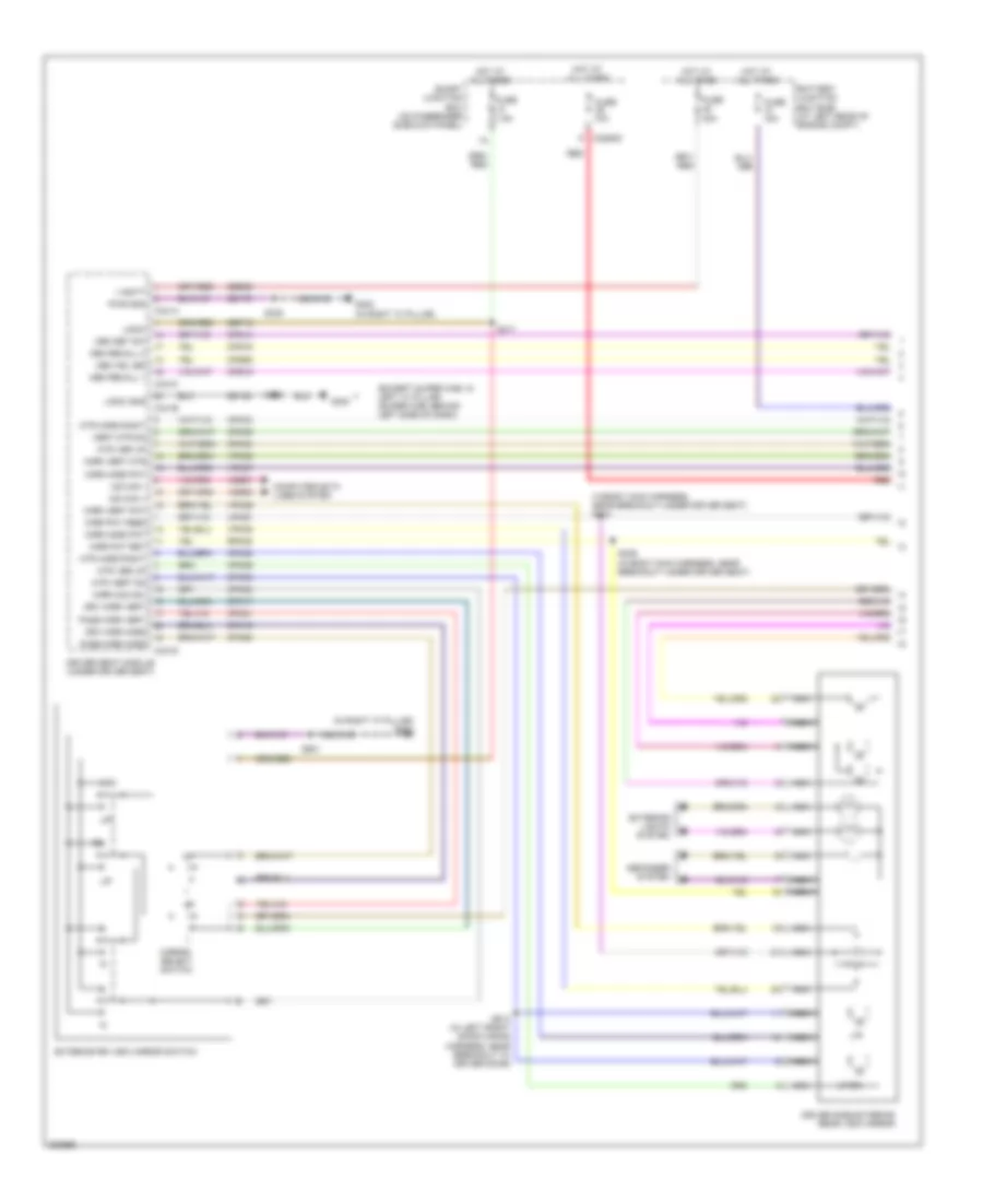 https://portal-diagnostov.com/license.html
Automotive Electricians Portal FZCO
Automotive Electricians Portal FZCO
https://portal-diagnostov.com/license.html
https://portal-diagnostov.com/license.html
Automotive Electricians Portal FZCO
Automotive Electricians Portal FZCOList of elements for Memory Mirrors Wiring Diagram, Late Production (1 of 2) for Ford Cab & Chassis F350 Super Duty 2008:
- (except super cab: in left "a" pillar) (super cab: behind left side of dash)
- (in body main harness, near breakout under driver seat) s318
- (in right "a" pillar) g302
- Battery junction box (bjb) (at left rear of engine compt)
- C2280d
- C341a
- C341b
- C341c
- C341d
- Computer data lines system
- Cpm03
- Cpm06
- Cpm16
- Cpm17
- Cpm20
- Cpm21
- Cpm23
- Cpm28
- Cpm29
- Cpm33
- Cpm34
- Cps14
- Cps15
- Cps16
- Cps55
- Defogger system
- Driver seat module (under driver seat)
- Driver side exterior rear view mirror
- Drv mirr horz
- Drv mirr vert
- Exterior lights system
- Exterior rr view mirror switch
- Fuse 10a
- Fuse 15a
- Fuse 30a
- Fuse 7.5a
- G300
- G302 (in right "a" pillar)
- Gd133
- Gd179
- Hot at all times
- L/r
- Logic
- Logic gnd
- Lpm30
- Mem ind led
- Mem recall 1
- Mem recall 2
- Mem set sw
- Mirr com sw
- Mirr horz pot
- Mirr pot feed
- Mirr pot ret
- Mirr vert mtr
- Mirr vert pot
- Mirror select switch
- Ms can +
- Ms can -
- Mtr horz right
- Mtr ver up
- Mtr vert dn
- Nca
- Pass mirr horz
- Pass mirr vert
- Pwr gnd
- Red
- Rpm30
- S317
- S326
- S336 (in body main harness, near breakout under driver seat)
- S338
- S501
- S513 (in left front door wiring harness, near breakout to driver door)
- Sbb45
- Sbp12
- Smart junction box (on passenger side kick panel)
- Up/dn
- V batt
- Vdb06
- Vdb07
- Vert mtr dn
- Vpm35
- Vpm36
- Vpm37
- Vpm38
Memory Mirrors Wiring Diagram, Late Production (2 of 2) for Ford Cab & Chassis F350 Super Duty 2008
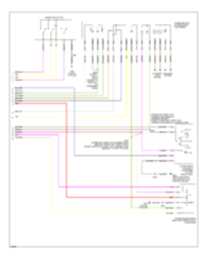 https://portal-diagnostov.com/license.html
Automotive Electricians Portal FZCO
Automotive Electricians Portal FZCO
https://portal-diagnostov.com/license.html
https://portal-diagnostov.com/license.html
Automotive Electricians Portal FZCO
Automotive Electricians Portal FZCOList of elements for Memory Mirrors Wiring Diagram, Late Production (2 of 2) for Ford Cab & Chassis F350 Super Duty 2008:
- (super cab: in body main harness, near breakout under driver seat) (except super cab: in body main harness, near breakout across floor)
- Defogger system
- Dn/up
- Exterior lights system
- G203 (behind center of dash, behind audio control module)
- G302 (in right "a" pillar)
- L/r
- Memory set switch
- Nca
- Out
- Passenger side exterior rear view mirror
- Power mirror fold relay (if equipped) (at left side of dash)
- Red
- S225
- S325
- S327 (super cab: in body main harness, near breakout behind left side of dash) (except super cab: in body main harness, near breakout to left "a" pillar)
- S501
- S609 (in right front door harness, in breakout to passenger door)
- Telescoping exterior rear view mirror switch (if equipped)
NAVIGATION
Navigation Wiring Diagram for Ford Cab & Chassis F350 Super Duty 2008
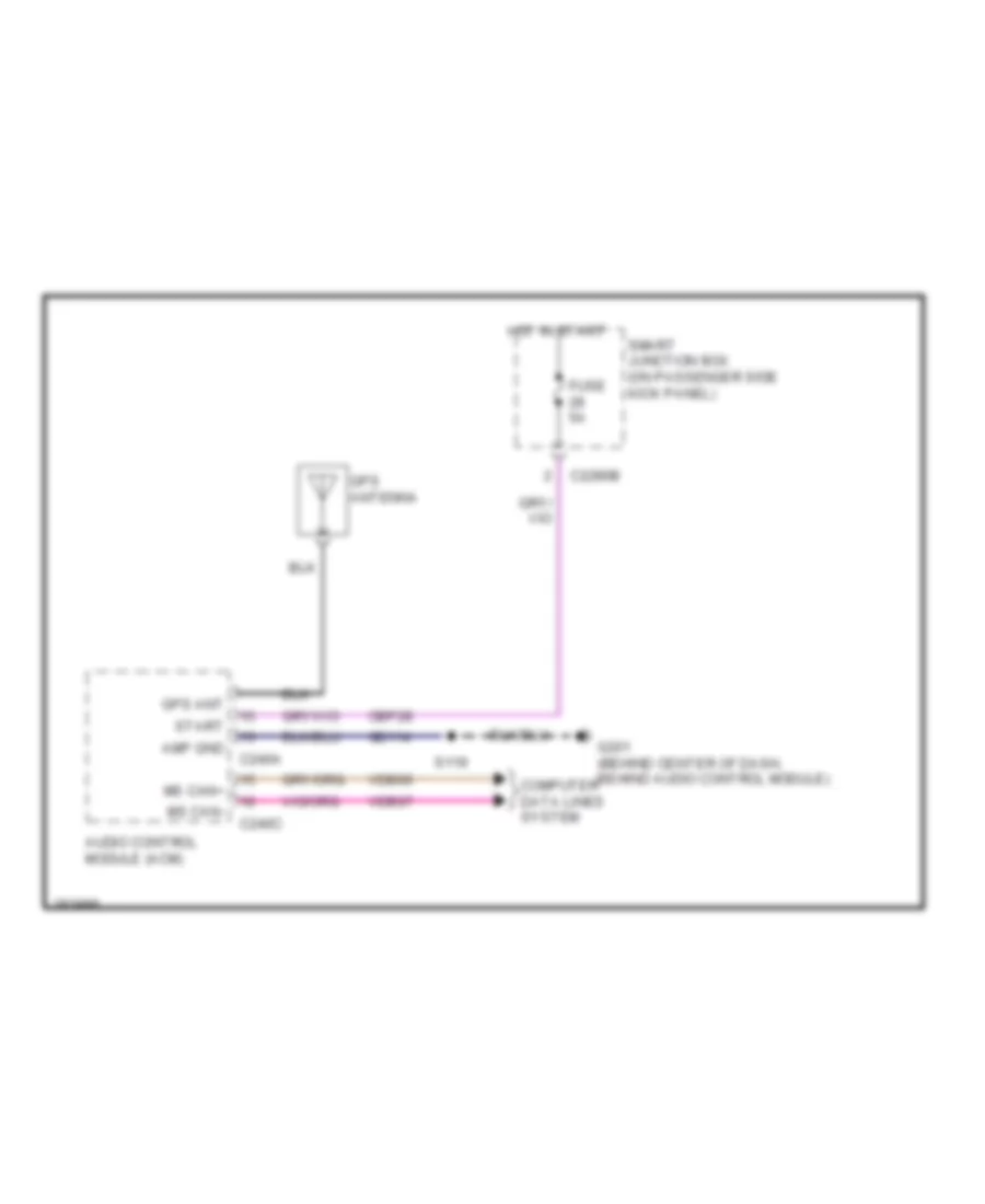 https://portal-diagnostov.com/license.html
Automotive Electricians Portal FZCO
Automotive Electricians Portal FZCO
https://portal-diagnostov.com/license.html
https://portal-diagnostov.com/license.html
Automotive Electricians Portal FZCO
Automotive Electricians Portal FZCOList of elements for Navigation Wiring Diagram for Ford Cab & Chassis F350 Super Duty 2008:
- Amp gnd
- Audio control module (acm)
- C2280b
- C240a
- C240c
- Cbp28
- Computer data lines system
- Fuse 5a
- G201 (behind center of dash, behind audio control module)
- Gd114
- Gps ant
- Gps antenna
- Hot in start
- Ms can+
- Ms can-
- S119
- Smart junction box (on passenger side kick panel)
- Start
- Vdb06
- Vdb07
Parking Assistant Wiring Diagram for Ford Cab & Chassis F350 Super Duty 2008
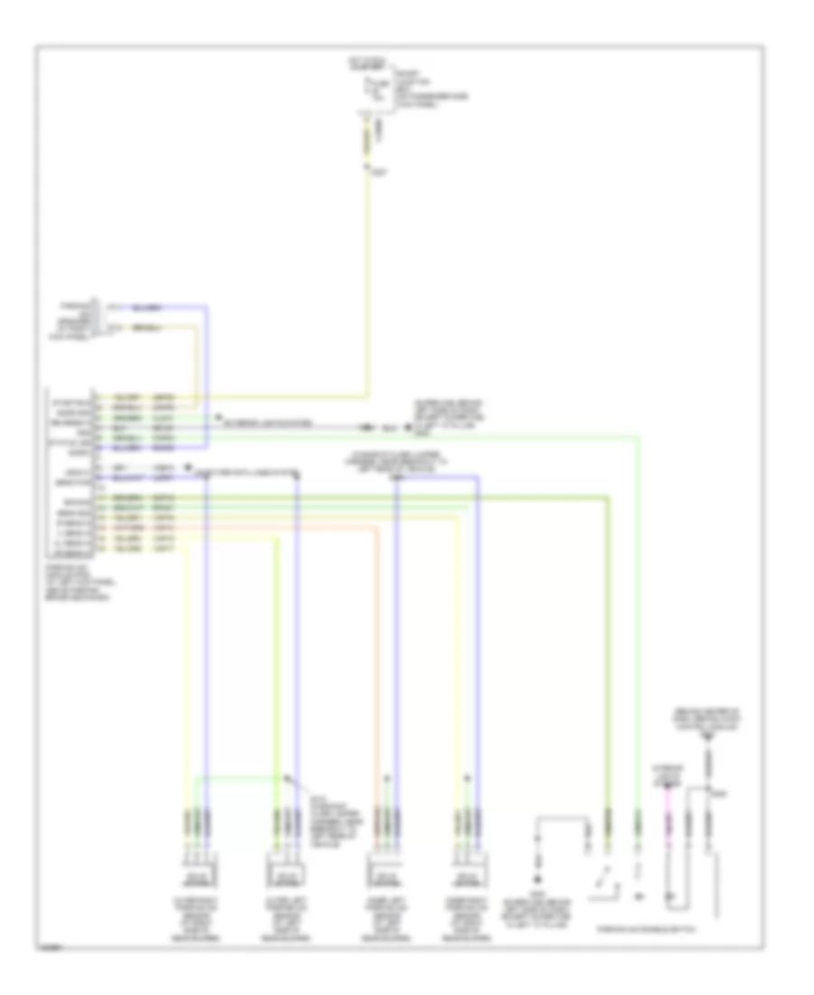 https://portal-diagnostov.com/license.html
Automotive Electricians Portal FZCO
Automotive Electricians Portal FZCO
https://portal-diagnostov.com/license.html
https://portal-diagnostov.com/license.html
Automotive Electricians Portal FZCO
Automotive Electricians Portal FZCOList of elements for Parking Assistant Wiring Diagram for Ford Cab & Chassis F350 Super Duty 2008:
- (behind center of dash, behind audio control module) g203
- (in backup alarm jumper harness, near breakout to left rear of vehicle) s416
- (super cab: behind left side of dash) (except super cab: in left "a" pillar) g300
- C2280b
- Cbp35
- Cls10
- Cmp02
- Cmp09
- Cmp18
- Computer data lines system
- Ena/dis
- Exterior lights system
- Fuse 10a
- G300 (super cab: behind left side of dash) (except super cab: in left "a" pillar)
- Gd133
- Gnd
- Hot in run or start
- Il sens in
- Inner left parking aid sensor (at left side of rear bumper)
- Inner right parking aid sensor (at right side of rear bumper)
- Interior lights system
- Ir sens in
- Iso9141
- Lmp07
- Ol sens in
- Or sens in
- Outer left parking aid sensor (at left side of rear bumper)
- Outer right parking aid sensor (at right side of rear bumper)
- Parking aid disable switch
- Parking aid module (pam) (at left kick panel, above parking brake mechanism)
- Parking aid speaker (at right kick panel)
- Reverse in
- Rmp09
- Rpm07
- S224
- S225
- S227
- S415 (in backup alarm jumper harness, near breakout to left rear of vehicle)
- Sens gnd
- Sens pwr
- Smart junction box (on passenger side kick panel)
- Sndr gnd
- Sndr+
- Solid state
- Start/run
- Status led
- Vdb10
- Vmp14
- Vmp15
- Vmp16
- Vmp17
Rear Camera Wiring Diagram for Ford Cab & Chassis F350 Super Duty 2008
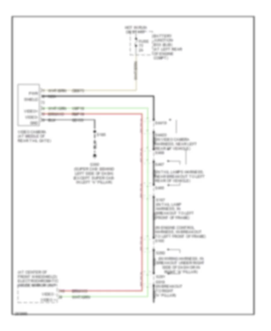 https://portal-diagnostov.com/license.html
Automotive Electricians Portal FZCO
Automotive Electricians Portal FZCO
https://portal-diagnostov.com/license.html
https://portal-diagnostov.com/license.html
Automotive Electricians Portal FZCO
Automotive Electricians Portal FZCOList of elements for Rear Camera Wiring Diagram for Ford Cab & Chassis F350 Super Duty 2008:
- (at center of front windshield) electrochromatic inside mirror unit
- (in engine control harness, in breakout to left front of frame) s165
- (in tail lamps harness, near breakout to left nca rear of vehicle)
- (in wiring harness, in breakout under right side of dash or in right "a" pillar)
- Battery junction box (bjb) (at left rear of engine compt)
- Cbb73
- Fuse 2a
- G300 (super cab: behind left side of dash) (except super cab: in left "a" pillar)
- Gd133
- Gnd
- Hot in run or start
- Nca
- Pwr
- Rmp19
- S167 (in tail lamp harness, in breakout to left front of frame)
- S185
- S291
- S292
- S4419
- S4420 (in video camera harness, near left nca rear of vehicle) s468
- S465
- S467
- S919 (in breakout to right nca "a" pillar)
- Shield
- Video +
- Video -
- Video camera (at middle of rear tail gate)
- Video+
- Video-
- Vmp19
POWER DISTRIBUTION
Power Distribution Wiring Diagram (1 of 7) for Ford Cab & Chassis F350 Super Duty 2008
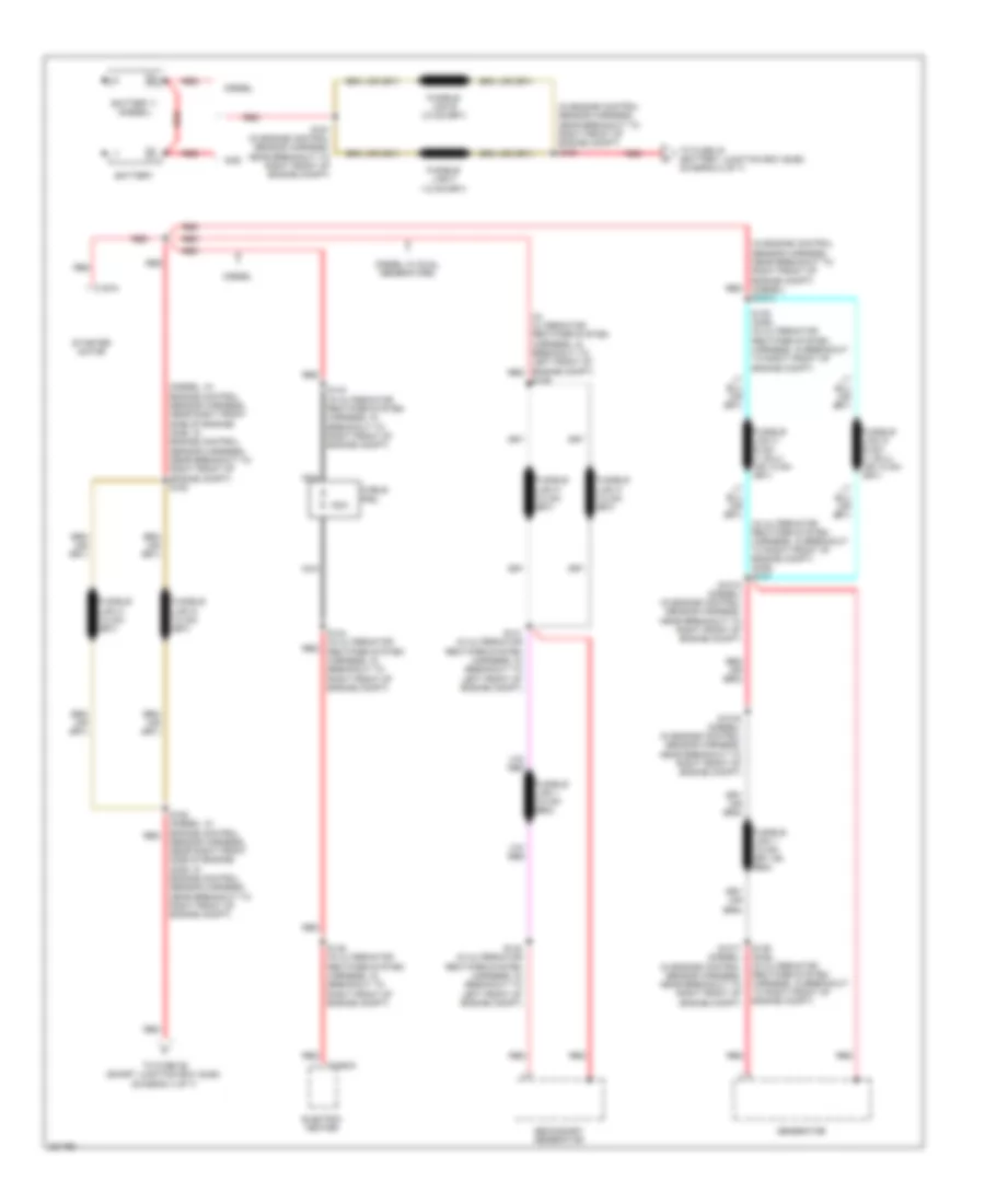 https://portal-diagnostov.com/license.html
Automotive Electricians Portal FZCO
Automotive Electricians Portal FZCO
https://portal-diagnostov.com/license.html
https://portal-diagnostov.com/license.html
Automotive Electricians Portal FZCO
Automotive Electricians Portal FZCOList of elements for Power Distribution Wiring Diagram (1 of 7) for Ford Cab & Chassis F350 Super Duty 2008:
- (diesel: in engine control sensor harness, near right front side of engine) (gas: in engine control sensor harness, near breakout to right front of engine compt) s153
- (in alternator rectifier system harness, in breakout to left front of engine compt) red
- (in alternator rectifier system harness, in breakout to right front of engine compt) (gas) s137
- (in engine control sensor harness, near breakout to right front of engine compt) (diesel) s1014
- (in engine control sensor harness, near breakout to right front of engine compt) s160
- 150a
- Battery
- Battery ii (diesel)
- C197a
- C2463a
- Cable pro
- Diesel
- Diesel w/ dual generators
- Electric heater
- Gas
- Generator
- Nca
- Red
- S1015 (diesel) (in engine control sensor harness, near breakout to right front of engine compt)
- S1016 (diesel) (in engine control sensor harness, near breakout to right front of engine compt)
- S1017 (diesel) (in engine control sensor harness, near breakout to right front of engine compt)
- S138 (gas) (in alternator rectifier system harness, in breakout to right front of engine compt)
- S139
- S139 (gas) (in alternator rectifier system harness, in breakout to right front of engine compt)
- S140 (in alternator rectifier system harness, in breakout to left front of engine compt)
- S141 (in alternator rectifier system harness, in breakout to left front of engine compt)
- S143 (in alternator rectifier system harness, in breakout to right front of engine compt)
- S144 (in alternator rectifier system harness, in breakout to right front of engine compt)
- S145 (in alternator rectifier system harness, in breakout to right front of engine compt)
- S152 (diesel: in engine control sensor harness, near right front side of engine) (gas: in engine control sensor harness, near breakout to right front of engine compt)
- S161 (in engine control sensor harness, near breakout to right front of engine compt)
- Secondary generator
- Starter motor
- To fuse 26 (smart junction box (sjb)) (diagram 4 of 7)
- To fuse 40 (battery junction box (bjb)) (diagram 2 of 7)
Power Distribution Wiring Diagram (2 of 7) for Ford Cab & Chassis F350 Super Duty 2008
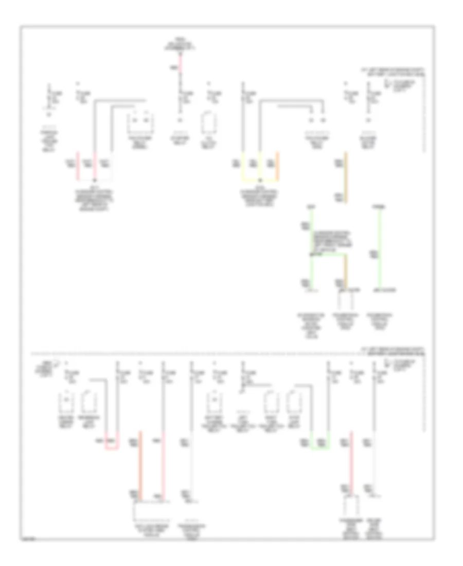 https://portal-diagnostov.com/license.html
Automotive Electricians Portal FZCO
Automotive Electricians Portal FZCO
https://portal-diagnostov.com/license.html
https://portal-diagnostov.com/license.html
Automotive Electricians Portal FZCO
Automotive Electricians Portal FZCOList of elements for Power Distribution Wiring Diagram (2 of 7) for Ford Cab & Chassis F350 Super Duty 2008:
- (at left rear of engine compt) battery junction box (bjb)
- (in engine control sensor harness, near breakout to left front corner of vehicle) s158
- A/c clutch relay
- Anti-lock brake system (abs) module
- Battery charge trailer tow relay
- Blower motor relay
- C1232b
- Diesel
- Driver side seat control switch
- Evaporative emission (evap) canister vent valve
- From c fuse 24 (diagram 2 of 7)
- From splice s160 (diagram 1 of 7)
- Fuse 10a
- Fuse 15a
- Fuse 20a
- Fuse 25a
- Fuse 30a
- Fuse 40a
- Fuse 50a
- Gas
- Heated mirror relay
- Left turn trailer tow relay
- Parking lamp trailer tow relay
- Passenger side seat control switch
- Pcm power relay (diesel)
- Pcm power relay (gas)
- Powertrain control module (pcm)
- Red
- Reversing lamp relay
- Right turn trailer tow relay
- S117 (in engine control sensor harness, near breakout to left rear of engine compt)
- S154 (in engine control sensor harness, near battery junction box)
- Starter relay
- Stop lamp relay
- To fuse 28 (diagram 2 of 7)
- To fuse 49 (diagram 3 of 7)
- Transmission control module (tcm)
Power Distribution Wiring Diagram (3 of 7) for Ford Cab & Chassis F350 Super Duty 2008
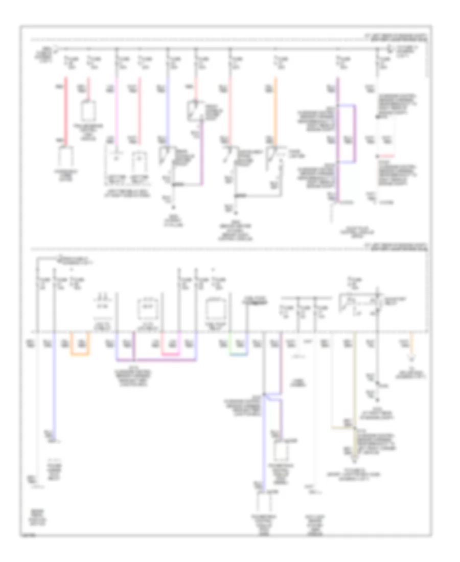 https://portal-diagnostov.com/license.html
Automotive Electricians Portal FZCO
Automotive Electricians Portal FZCO
https://portal-diagnostov.com/license.html
https://portal-diagnostov.com/license.html
Automotive Electricians Portal FZCO
Automotive Electricians Portal FZCOList of elements for Power Distribution Wiring Diagram (3 of 7) for Ford Cab & Chassis F350 Super Duty 2008:
- (at left rear of engine compt) battery junction box (bjb)
- (in engine control sensor harness, near breakout to right rear of engine compt) s103
- Anti-lock brake system (abs) module
- Brake pedal position switch
- C1232b
- C1273a
- C1273b
- C175b
- Cigar lighter
- From d fuse 45 (diagram 2 of 7)
- From fuse 47 (diagram 3 of 7)
- Front console power point
- Fuel pump motor diode
- Fuel pump relay
- Fuse 10a
- Fuse 15a
- Fuse 20a
- Fuse 2a
- Fuse 30a
- Fuse 40a
- Fuse 50a
- Fuse 5a
- G103 (at right rear of engine compt)
- G203 (behind center of dash, behind audio control module)
- G302 (in right "a" pillar)
- Glow plug control module (gpcm)
- Hi to low relay
- Instrument panel power point
- Low to hi relay
- Power mirror fold relay
- Powertrain control module (pcm) (diesel)
- Powertrain control module (pcm) (gas)
- Rear console power point
- Red
- Run/start relay
- S1000 (in engine control sensor harness, near breakout to right rear of engine compt)
- S1003 (in engine control sensor harness, near breakout to right rear of engine compt)
- S118 (in engine control sensor harness, near battery junction box)
- S119 (in engine control sensor harness, near breakout to left front corner of vehicle)
- S123 (in engine control sensor harness, near battery junction box)
- S124 (in engine control sensor harness, near breakout to right rear of engine compt)
- S162
- S225
- S323
- To fuse 13 (diagram 3 of 7)
- To fuse 33 (smart junction box (sjb)) (diagram 4 of 7)
- To splice s233 (diagram 4 of 7)
- Trailer brake control (tbc) module
- Upfitter relay 1
- Upfitter relay 2
- Upfitter relay box (at right side of dash)
- Video camera
- Windshield wiper motor
Power Distribution Wiring Diagram (4 of 7) for Ford Cab & Chassis F350 Super Duty 2008
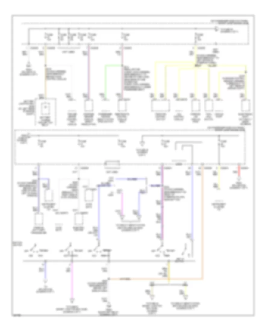 https://portal-diagnostov.com/license.html
Automotive Electricians Portal FZCO
Automotive Electricians Portal FZCO
https://portal-diagnostov.com/license.html
https://portal-diagnostov.com/license.html
Automotive Electricians Portal FZCO
Automotive Electricians Portal FZCOList of elements for Power Distribution Wiring Diagram (4 of 7) for Ford Cab & Chassis F350 Super Duty 2008:
- (not used)
- (on passenger side kick panel) smart junction box (sjb)
- 4x4 control module
- Acc
- Battery charge trailer tow relay
- Battery junction box (bjb) (at left rear of engine compt)
- C2280a
- C2280b
- C2280d
- C2280e
- C2280h
- C2357a
- C2463c
- C281b
- Compass sensor module (early production)
- Electric heater
- Electronic shift on the fly (esof) solenoid
- From h fuse 35 (diagram 4 of 7)
- From run/start relay (diagram 3 of 7)
- From splice s119 (diagram 3 of 7)
- From splice s152 (diagram 1 of 7)
- Fuse 10a
- Fuse 20a
- Fuse 5a
- Fuse 7.5a
- Hvac eatc
- Hvac emtc
- Ignition switch
- Instrument cluster (ic)
- Key in switch
- Logic
- Off
- Parking aid module (pam)
- Passenger air bag deactivation (pad) switch
- Passive anti-theft transceiver
- Red
- Restraints control module (rcm)
- Run
- S105 (in engine control sensor harness, in breakout to left rear of engine compt)
- S206 (in main harness, near breakout to right side of hvac housing)
- S216 (in main harness, near breakout behind audio control module)
- S223 (in main harness, near breakout behind left side of dash, left of radio opening)
- S233 (in main harness, near breakout behind left side of dash)
- S240 (in main harness, near breakout on front of steering column, near bottom)
- S314 (regular cab: in body main harness, near breakout to center of cab floor, near rear of cab) (super cab: in body main harness, near breakout under passenger seat)
- Start
- To circuit deactivation ignition module (cdim) (diagram 5 of 7)
- To fuse 36 (diagram 4 of 7)
- To fuse 38 (diagram 5 of 7)
- To fuse 43 (smart junction box (sjb)) (diagram 5 of 7)
- To fuse 44 (smart junction box (sjb)) (diagram 5 of 7)
- To splice s126 (diagram 5 of 7)
- Towl haul switch
- Traction control switch
- Trailer brake control (tbc) module
- Vacuum pump
- W/ cdim
- W/o cdim
Power Distribution Wiring Diagram (5 of 7) for Ford Cab & Chassis F350 Super Duty 2008
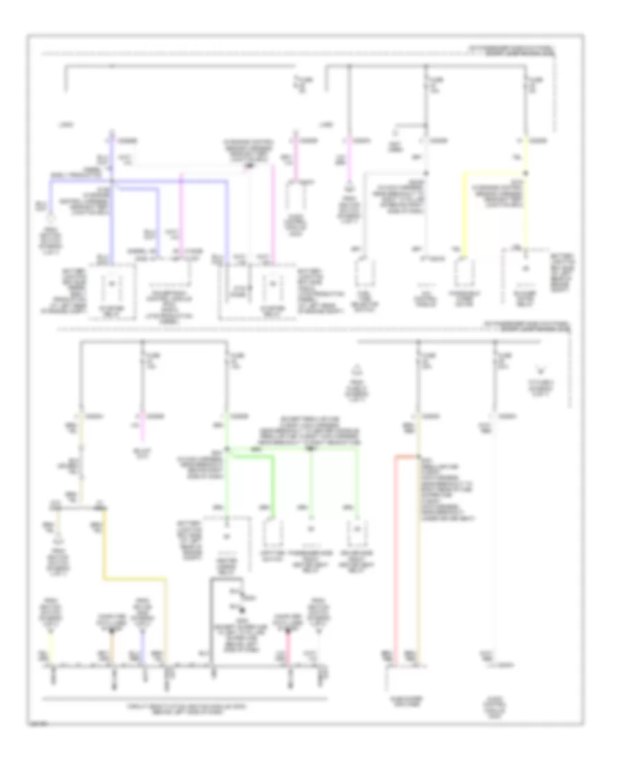 https://portal-diagnostov.com/license.html
Automotive Electricians Portal FZCO
Automotive Electricians Portal FZCO
https://portal-diagnostov.com/license.html
https://portal-diagnostov.com/license.html
Automotive Electricians Portal FZCO
Automotive Electricians Portal FZCOList of elements for Power Distribution Wiring Diagram (5 of 7) for Ford Cab & Chassis F350 Super Duty 2008:
- (diesel)
- (except regular cab: in body main harness, near breakout to center console) (regular cab: in body main harness, near breakout to right rear of cab) s310
- (gas)
- (in engine control sensor harness, near battery junction box) s157
- (not used)
- (on passenger side kick panel) smart junction box (sjb)
- 4x4 control module
- Audio control module (acm)
- Batt
- Battery junction box (bjb) (at left rear of engine compt)
- Battery junction box (bjb) (diesel early production) (at left rear of engine compt)
- Battery junction box (bjb) (gas & late production diesel) (at left rear of engine compt)
- Blower motor relay
- C1232b
- C175t
- C2280a
- C2280b
- C2280d
- C2280e
- C240a
- C281b
- Circuit deactivation ignition module (cdim) (behind left side of dash)
- Computer data lines system
- Diesel early production
- Driver side front heated seat relay
- From fuse 27 (diagram 4 of 7)
- From ignition switch (diagram 4 of 7)
- From splice s240 (diagram 4 of 7)
- Fuel tank selector switch
- Fuse 10a
- Fuse 20a
- Fuse 5a
- G300 (except super cab: in left "a" pillar) (super cab: behind left side of dash)
- Gnd
- Heated mirror relay
- Logic
- Ms can+
- Ms can-
- Otis diode
- Passenger side front heated seat relay
- Powertrain control module (pcm) (gas & late production diesel)
- Run in
- S104 (in engine control sensor harness, near battery junction box)
- S126 (in engine control harness, near battery junction box)
- S201 (in main harness, near breakout behind right side of dash)
- S224
- S2439 (in main harness, near breakout to right "a" pillar or behind right side of dash)
- S321 (regular cab: in body main harness, near breakout to right rear of cab) (super cab: in body main harness, near breakout under driver seat)
- Starter relay
- Subwoofer amplifier
- To fuse 2 (diagram 6 of 7)
- Upfitter switch
- W/ cdim
- W/o cdim
- Windshield wiper motor
Power Distribution Wiring Diagram (6 of 7) for Ford Cab & Chassis F350 Super Duty 2008
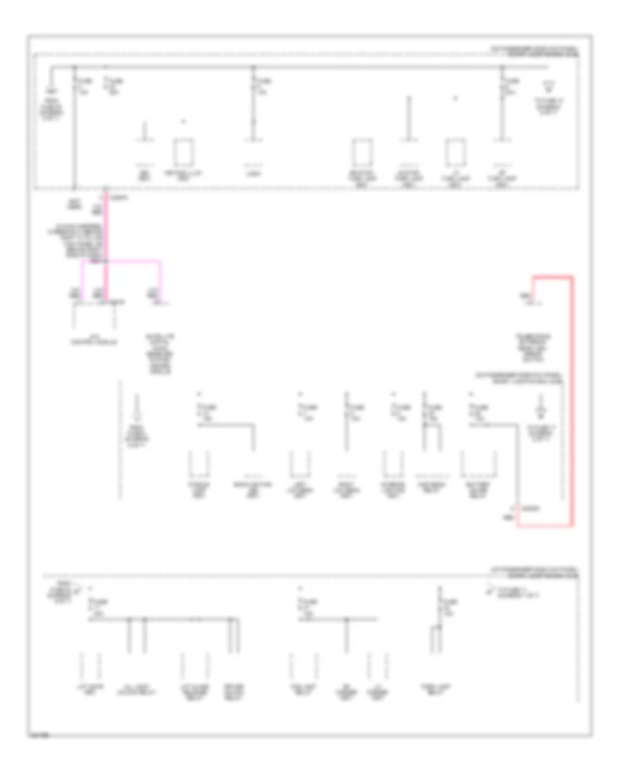 https://portal-diagnostov.com/license.html
Automotive Electricians Portal FZCO
Automotive Electricians Portal FZCO
https://portal-diagnostov.com/license.html
https://portal-diagnostov.com/license.html
Automotive Electricians Portal FZCO
Automotive Electricians Portal FZCOList of elements for Power Distribution Wiring Diagram (6 of 7) for Ford Cab & Chassis F350 Super Duty 2008:
- (in main harness, in breakout behind right "a" pillar kick panel or behind right side of dash) s204
- (not used)
- (on passenger side kick panel) smart junction box (sjb)
- 4x4 control module
- All lock/ unlock relay
- Backlighting led (fet)
- Battery saver relay
- Bs1 (fet)
- C2280a
- C2280d
- Driver unlock relay
- Fog lamp relay
- From fuse 25 r (diagram 6 of 7)
- From fuse 39 (diagram 5 of 7)
- From fuse 6 (diagram 6 of 7)
- Fuse 10a
- Fuse 15a
- Fuse 20a
- High beam relay
- Interior lighting (fet)
- Keypad illum (fet)
- Left low beam (fet)
- Lf turn lamp (fet)
- Lh corner (fet)
- Lift gate (fet)
- Lift glass release relay
- Logic
- Lr stop/ turn lamp (fet)
- Park lamp relay
- Puddle lamp (fet)
- Red
- Rf turn lamp (fet)
- Rh corner (fet)
- Right low beam (fet)
- Rr stop/ turn lamp (fet)
- Satellite digital audio receiver system (sdars) module
- Telescoping exterior rear view mirror switch
- To fuse 10 (diagram 6 of 7)
- To fuse 11 (diagram 7 of 7)
- To fuse 17 (diagram 6 of 7)
Power Distribution Wiring Diagram (7 of 7) for Ford Cab & Chassis F350 Super Duty 2008
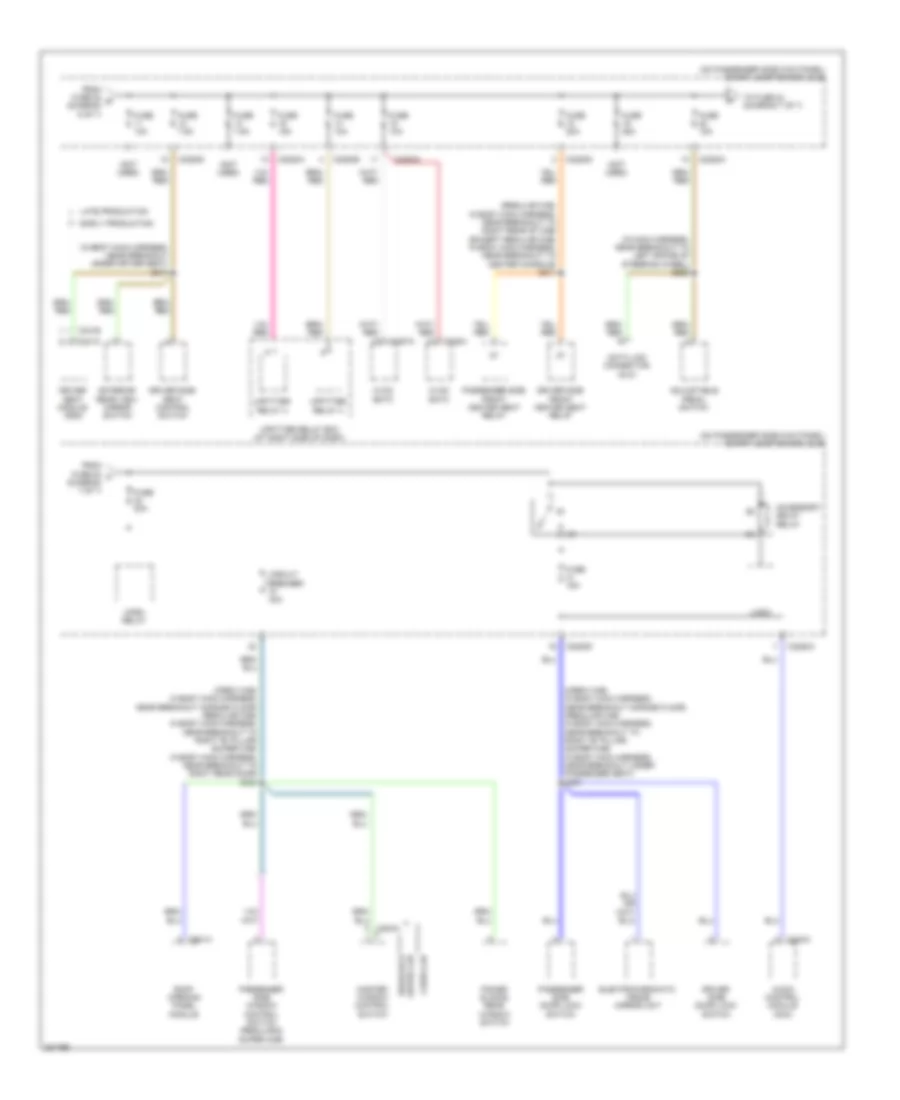 https://portal-diagnostov.com/license.html
Automotive Electricians Portal FZCO
Automotive Electricians Portal FZCO
https://portal-diagnostov.com/license.html
https://portal-diagnostov.com/license.html
Automotive Electricians Portal FZCO
Automotive Electricians Portal FZCOList of elements for Power Distribution Wiring Diagram (7 of 7) for Ford Cab & Chassis F350 Super Duty 2008:
- (crew cab: in body main harness, near breakout across floor) (regular cab: in body main harness, near breakout to right "b" pillar) (super cab: in body main harness, near breakout to right rear door) s303
- (crew cab: in body main harness, near breakout across floor) (regular cab: in body main harness, near breakout to right "b" pillar) (super cab: in body main harness, near breakout under passenger seat) s301
- (in body main harness, near breakout under driver seat) s317
- (in main harness, near breakout to left spoke of steering wheel) s228
- (not used)
- (on passenger side kick panel) smart junction box (sjb)
- (regular cab: in body main harness, near breakout to right rear of cab) (except regular cab: in body main harness, near breakout to center console) s311
- Accessory delay relay
- Adjustable pedal switch
- Audio control module (acm)
- C2280a
- C2280b
- C2280d
- C228a
- C2357a
- C240a
- C341b
- C341c
- C921a
- Circuit breaker 30a
- Crew cab
- Data link connector (dlc)
- Driver seat module (dsm)
- Driver side door lock switch
- Driver side front heated seat relay
- Driver side seat control switch
- Early production
- Electrochromatic inside mirror unit
- Exterior rear view mirror switch
- From fuse 20 t (diagram 7 of 7)
- From fuse 22 s (diagram 6 of 7)
- Fuse 10a
- Fuse 15a
- Fuse 20a
- Fuse 25a
- Fuse 7.5a
- Horn relay
- Hvac eatc
- Hvac emtc
- Late production
- Logic
- Master window control switch
- Passenger side door lock switch
- Passenger side front heated seat relay
- Passenger side window control switch (regular & super cab)
- Power sliding rear window switch
- Regular & super cab
- Roof opening panel module
- To fuse 24 (diagram 7 of 7)
- Upfitter relay 3
- Upfitter relay 4
- Upfitter relay box (at right side of dash)
POWER DOOR LOCKS
Power Door Locks Wiring Diagram (1 of 2) for Ford Cab & Chassis F350 Super Duty 2008
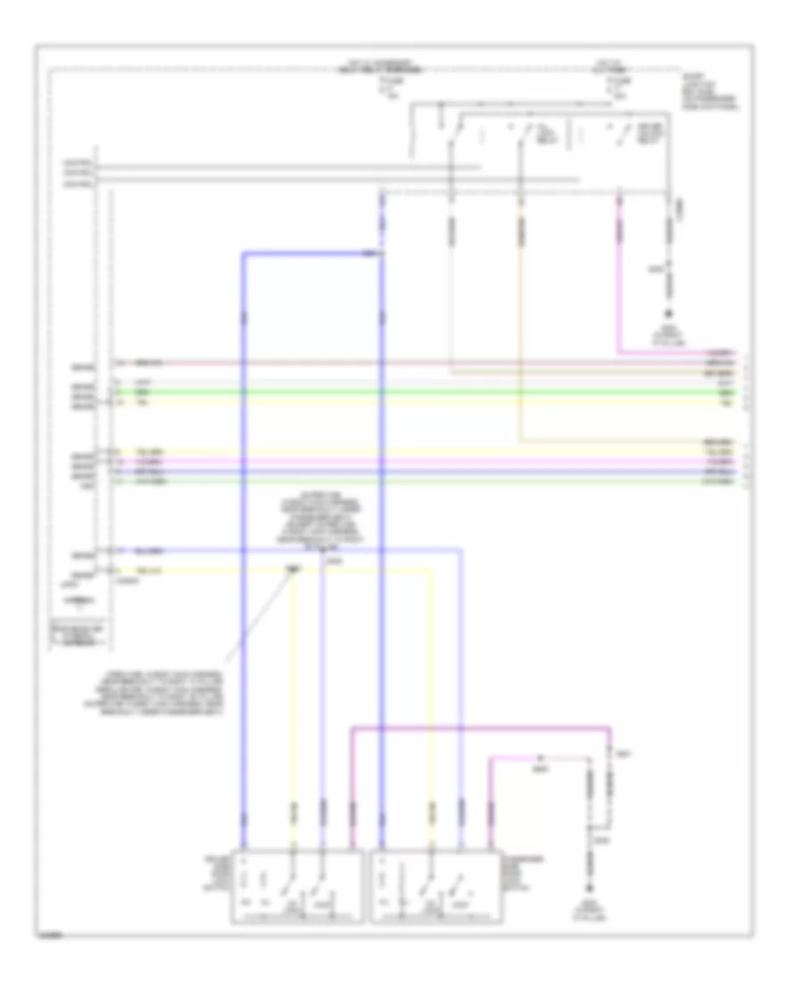 https://portal-diagnostov.com/license.html
Automotive Electricians Portal FZCO
Automotive Electricians Portal FZCO
https://portal-diagnostov.com/license.html
https://portal-diagnostov.com/license.html
Automotive Electricians Portal FZCO
Automotive Electricians Portal FZCOList of elements for Power Door Locks Wiring Diagram (1 of 2) for Ford Cab & Chassis F350 Super Duty 2008:
- (crew cab: in body main harness, near breakout to right "a" pillar) (regular cab: in body main harness, near breakout to right "b" pillar) (super cab: in body main harness, near breakout under passenger seat)
- (super cab: in body main harness, near breakout under passenger seat) (except super cab: in body main harness, near breakout to right "b" pillar)
- All lock relay
- Antenna
- C2280c
- C2280d
- Control
- Driver side door lock switch
- Driver unlock relay
- Fuse 15a
- Fuse 20a
- G302 (in right "a" pillar)
- Hot at all times
- Hot w/ accessory delay relay energized
- Hsd
- Lock
- Logic
- Passenger side door lock switch
- Rke receiver internal antenna
- S301
- S305
- S306
- S308
- S501
- S639
- Sense
- Smart junction box (sjb) (on passenger side kick panel)
- Un lock
Power Door Locks Wiring Diagram (2 of 2) for Ford Cab & Chassis F350 Super Duty 2008
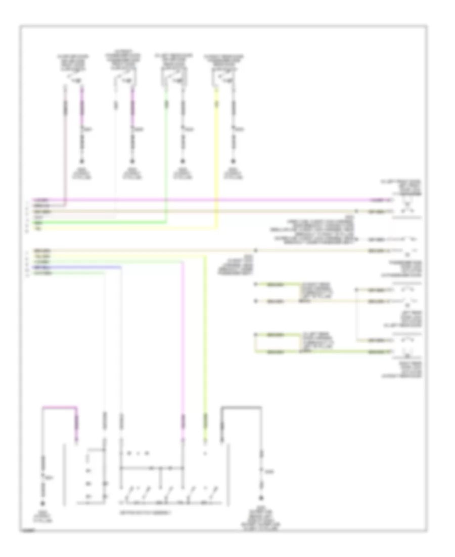 https://portal-diagnostov.com/license.html
Automotive Electricians Portal FZCO
Automotive Electricians Portal FZCO
https://portal-diagnostov.com/license.html
https://portal-diagnostov.com/license.html
Automotive Electricians Portal FZCO
Automotive Electricians Portal FZCOList of elements for Power Door Locks Wiring Diagram (2 of 2) for Ford Cab & Chassis F350 Super Duty 2008:
- (in driver door) driver side front door ajar switch
- (in front passenger door) passenger side front door ajar switch
- (in left front door) left front door lock actuator
- (in left rear door harness, in breakout to left "b" pillar) s800
- (in left rear door) driver side rear door ajar switch
- (in right rear door harness, in breakout to left "b" pillar) s700
- (in right rear door) passenger side rear door ajar switch
- 1/2
- 3/4
- 5/6
- 7/8
- 9/0
- Ajar
- G300 (super cab: behind left side of dash) (except super cab: in left "a" pillar)
- G302 (in right "a" pillar)
- Keypad switch assembly
- Left rear door lock actuator (in left rear door)
- Passenger side door lock actuator (in passenger door)
- Right rear door lock actuator (in right rear door)
- S302 (crew cab: in body main harness, near breakout across floor) (regular cab: in body main harness, near breakout to right "b" pillar) (super cab: in body main harness, near breakout under passenger seat)
- S308
- S323
- S326
- S333 (in body main harness, near breakout under passenger seat)
- S501
- S639
POWER MIRRORS
Electrochromic Mirror Wiring Diagram, Early Production for Ford Cab & Chassis F350 Super Duty 2008
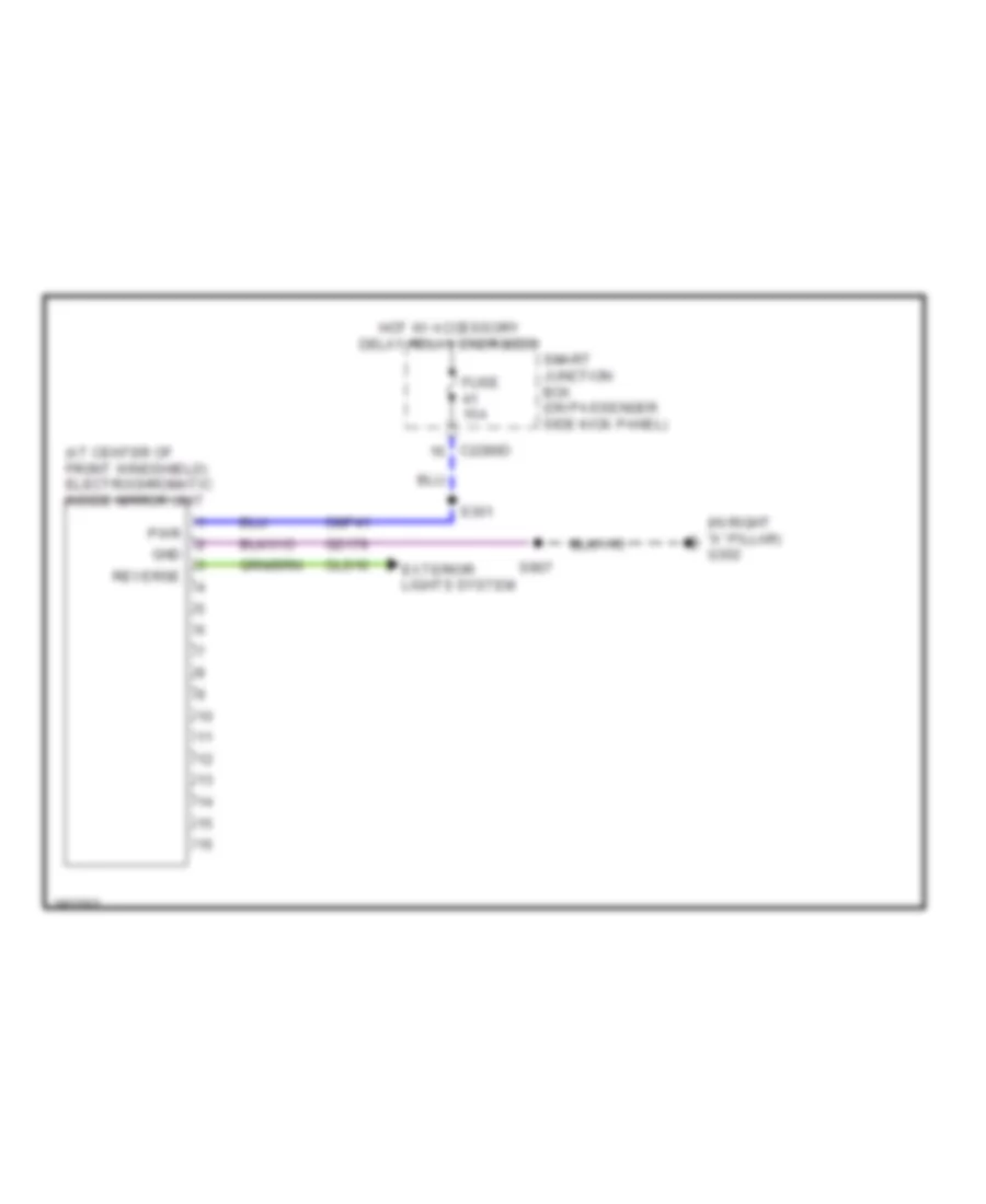 https://portal-diagnostov.com/license.html
Automotive Electricians Portal FZCO
Automotive Electricians Portal FZCO
https://portal-diagnostov.com/license.html
https://portal-diagnostov.com/license.html
Automotive Electricians Portal FZCO
Automotive Electricians Portal FZCOList of elements for Electrochromic Mirror Wiring Diagram, Early Production for Ford Cab & Chassis F350 Super Duty 2008:
- (at center of front windshield) electrochromatic inside mirror unit
- (in right "a" pillar) g302
- C2280d
- Cls10
- Cmp41
- Exterior lights system
- Fuse 15a
- Gd179
- Gnd
- Hot w/ accessory delay relay energized
- Pwr
- Reverse
- S301
- S907
- Smart junction box (on passenger side kick panel)
Electrochromic Mirror Wiring Diagram, Late Production for Ford Cab & Chassis F350 Super Duty 2008
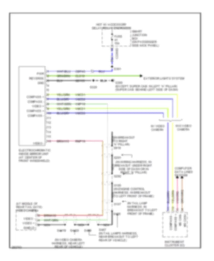 https://portal-diagnostov.com/license.html
Automotive Electricians Portal FZCO
Automotive Electricians Portal FZCO
https://portal-diagnostov.com/license.html
https://portal-diagnostov.com/license.html
Automotive Electricians Portal FZCO
Automotive Electricians Portal FZCOList of elements for Electrochromic Mirror Wiring Diagram, Late Production for Ford Cab & Chassis F350 Super Duty 2008:
- (at middle of rear tail gate) video camera
- (in breakout to right nca "a" pillar) s919
- (in tail lamp harness, in breakout to left front of frame)
- (in video camera harness, near left rear of vehicle)
- (in wiring harness, in breakout under right side of dash or in right "a" pillar)
- C2280d
- Cbp46
- Cls10
- Compass +
- Compass -
- Computer data lines system
- Electrochromatic inside mirror unit (at center of front windshield)
- Exterior lights system
- Fuse 15a
- G300 (except super cab: in left "a" pillar) (super cab: behind left side of dash)
- Gd133
- Gnd
- Hot w/ accessory delay relay energized
- Instrument cluster (ic)
- Ms can+
- Ms can-
- Nca
- Pwr
- Reverse
- Rmp19
- S165 (in engine control harness, in breakout to left front of frame)
- S167
- S291
- S292
- S301
- S326
- S4419
- S4420
- S465
- S467 (in tail lamps harness, near breakout to left rear of vehicle)
- S468
- Shield
- Smart junction box (on passenger side kick panel)
- Video +
- Video -
- Vmc30
- Vmc31
- Vmp19
- W/ video camera
- W/o video camera
Power Mirrors Wiring Diagram for Ford Cab & Chassis F350 Super Duty 2008
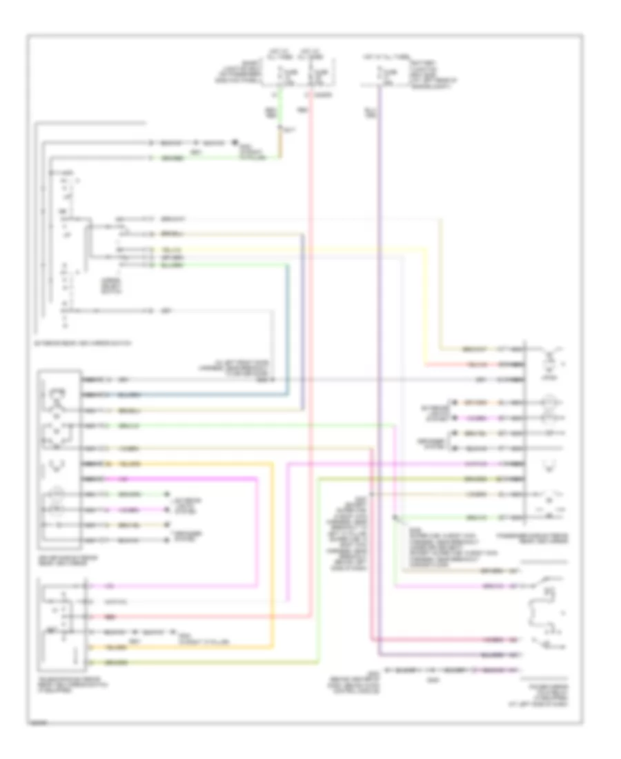 https://portal-diagnostov.com/license.html
Automotive Electricians Portal FZCO
Automotive Electricians Portal FZCO
https://portal-diagnostov.com/license.html
https://portal-diagnostov.com/license.html
Automotive Electricians Portal FZCO
Automotive Electricians Portal FZCOList of elements for Power Mirrors Wiring Diagram for Ford Cab & Chassis F350 Super Duty 2008:
- (in left front door harness, near breakout to driver door) s500
- Battery junction box (bjb) (at left rear of engine compt)
- C2280d
- Defogger
- Defogger system
- Driver side exterior rear view mirror
- Exterior
- Exterior lights system
- Exterior rear view mirror switch
- Fuse 10a
- Fuse 15a
- Fuse 7.5a
- G203 (behind center of dash, behind audio control module)
- G302 (in right "a" pillar)
- Hot at all times
- L/r
- Lights system
- Mirror select switch
- Nca
- Out
- Passenger side exterior rear view mirror
- Power mirror fold relay (if equipped) (at left side of dash)
- Red
- S225
- S317
- S325 (super cab: in body main harness, near breakout under driver seat) (except super cab: in body main harness, near breakout across floor)
- S327 (except super cab: in body main harness, near breakout to left "a" pillar) (super cab: in body main harness, near breakout behind left side of dash)
- S501
- Smart junction box (on passenger side kick panel)
- System
- Telescoping exterior rear view mirror switch (if equipped)
- Up/dn
POWER SEATS
Adjustable Pedal Wiring Diagram for Ford Cab & Chassis F350 Super Duty 2008
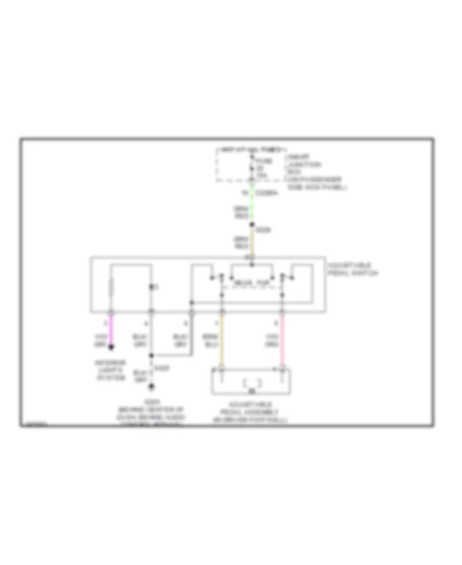 https://portal-diagnostov.com/license.html
Automotive Electricians Portal FZCO
Automotive Electricians Portal FZCO
https://portal-diagnostov.com/license.html
https://portal-diagnostov.com/license.html
Automotive Electricians Portal FZCO
Automotive Electricians Portal FZCOList of elements for Adjustable Pedal Wiring Diagram for Ford Cab & Chassis F350 Super Duty 2008:
- Adjustable pedal assembly (in driver footwell)
- Adjustable pedal switch
- C2280a
- Far
- Fuse 15a
- G203 (behind center of dash, behind audio control module)
- Hot at all times
- Interior lights system
- Near
- S228
- Smart junction box (on passenger side kick panel)
Driver Power Seat Wiring Diagram for Ford Cab & Chassis F350 Super Duty 2008
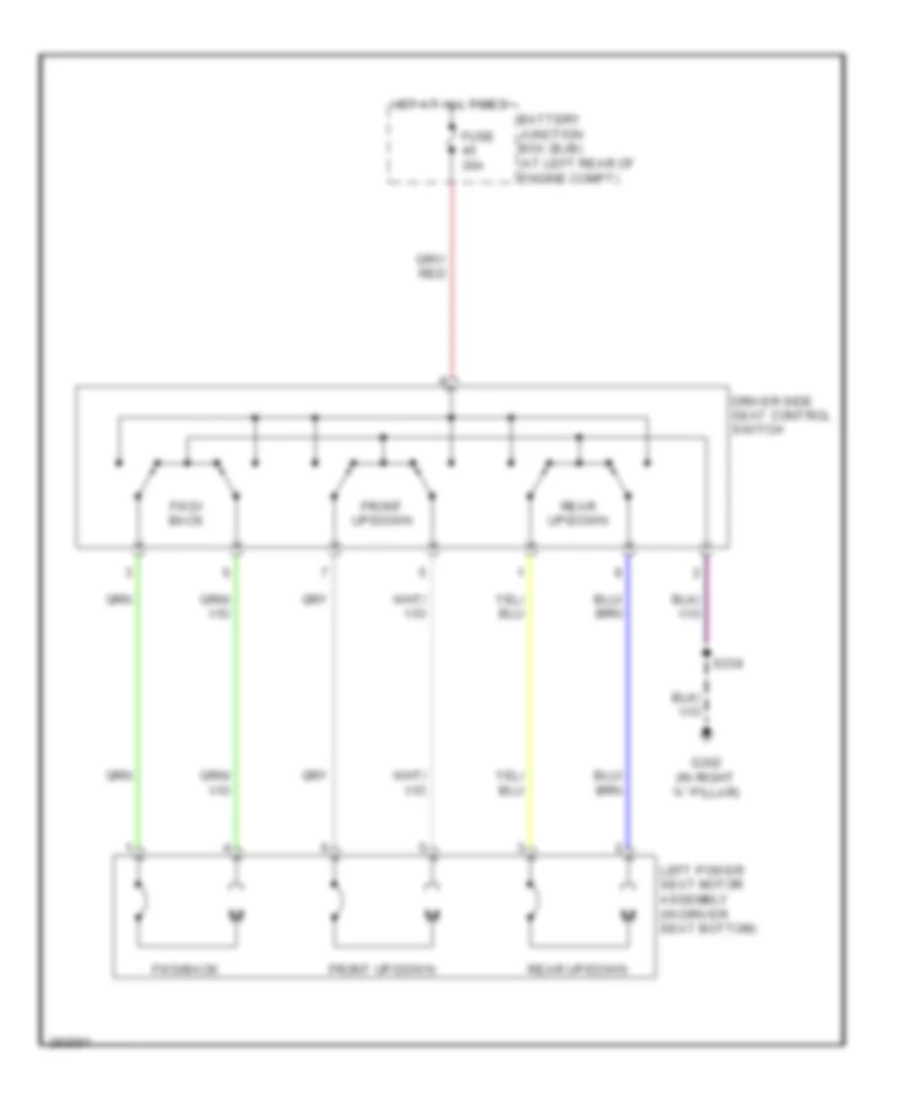 https://portal-diagnostov.com/license.html
Automotive Electricians Portal FZCO
Automotive Electricians Portal FZCO
https://portal-diagnostov.com/license.html
https://portal-diagnostov.com/license.html
Automotive Electricians Portal FZCO
Automotive Electricians Portal FZCOList of elements for Driver Power Seat Wiring Diagram for Ford Cab & Chassis F350 Super Duty 2008:
- Battery junction box (bjb) (at left rear of engine compt)
- Driver side seat control switch
- Front up/down
- Fuse 30a
- Fwd/ back
- Fwd/back
- G302 (in right "a" pillar)
- Hot at all times
- Left power seat motor assembly (in driver seat bottom)
- Rear up/down
- S338
Heated Seats Wiring Diagram for Ford Cab & Chassis F350 Super Duty 2008
 https://portal-diagnostov.com/license.html
Automotive Electricians Portal FZCO
Automotive Electricians Portal FZCO
https://portal-diagnostov.com/license.html
https://portal-diagnostov.com/license.html
Automotive Electricians Portal FZCO
Automotive Electricians Portal FZCOList of elements for Heated Seats Wiring Diagram for Ford Cab & Chassis F350 Super Duty 2008:
- Automatic a/c
- C2280b
- C2280d
- C228b
- C2357a
- Driver side front heated seat relay (below driver seat)
- Drv seat heater switch
- Fuse 10a
- Fuse 20a
- G302 (in right "a" pillar)
- Hot at all times
- Hot in run
- Hvac-eatc
- Hvac-emtc
- Left front seat back rest heater mat (in driver seat back)
- Left front seat cushion heater mat (in driver seat)
- Manual a/c
- Pass seat heater switch
- Passenger side front heated seat relay (below passenger seat)
- Right front seat back rest heater mat (in front passenger seat back)
- Right front seat cushion heater mat (in front passenger seat cushion)
- S310
- S311
- S338
- S339
- Smart junction box (on passenger side kick panel)
Passenger Power Seat Wiring Diagram for Ford Cab & Chassis F350 Super Duty 2008
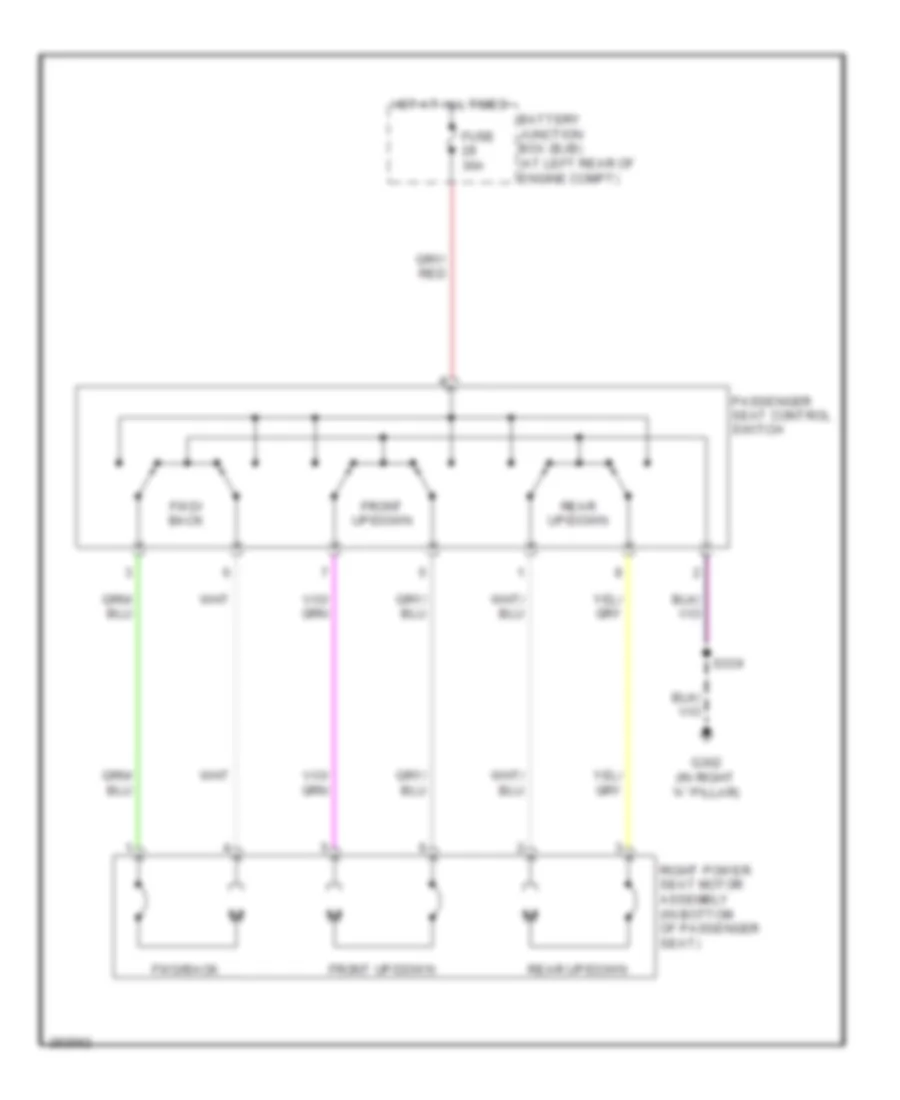 https://portal-diagnostov.com/license.html
Automotive Electricians Portal FZCO
Automotive Electricians Portal FZCO
https://portal-diagnostov.com/license.html
https://portal-diagnostov.com/license.html
Automotive Electricians Portal FZCO
Automotive Electricians Portal FZCOList of elements for Passenger Power Seat Wiring Diagram for Ford Cab & Chassis F350 Super Duty 2008:
- Battery junction box (bjb) (at left rear of engine compt)
- Front up/down
- Fuse 30a
- Fwd/ back
- Fwd/back
- G302 (in right "a" pillar)
- Hot at all times
- Passenger seat control switch
- Rear up/down
- Right power seat motor assembly (in bottom of passenger seat)
- S339
POWER TOP/SUNROOF
Power Top/Sunroof Wiring Diagram for Ford Cab & Chassis F350 Super Duty 2008
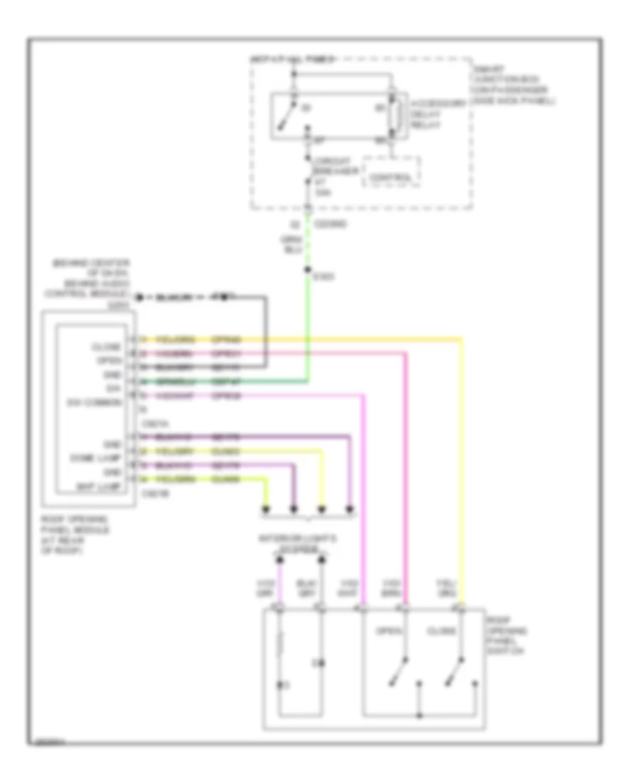 https://portal-diagnostov.com/license.html
Automotive Electricians Portal FZCO
Automotive Electricians Portal FZCO
https://portal-diagnostov.com/license.html
https://portal-diagnostov.com/license.html
Automotive Electricians Portal FZCO
Automotive Electricians Portal FZCOList of elements for Power Top/Sunroof Wiring Diagram for Ford Cab & Chassis F350 Super Duty 2008:
- (behind center of dash, behind audio control module)
- Accessory delay relay
- C2280d
- C921a
- C921b
- Cbp47
- Circuit breaker 30a
- Cln03
- Cln09
- Close
- Control
- Cpr31
- Cpr39
- Cpr40
- D/a
- Dome lamp
- G203
- Gd115
- Gd179
- Gnd
- Hot at all times
- Interior lights system
- Map lamp
- Open
- Roof opening panel module (at rear of roof)
- Roof opening panel switch
- S303
- S910
- Smart junction box (on passenger side kick panel)
- Sw common
POWER WINDOWS
Power Windows Wiring Diagram, Crew Cab (1 of 2) for Ford Cab & Chassis F350 Super Duty 2008
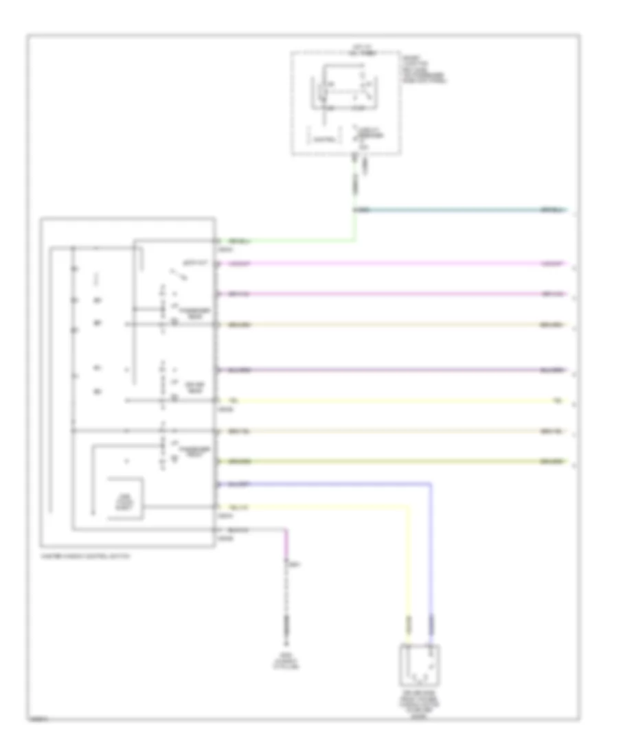 https://portal-diagnostov.com/license.html
Automotive Electricians Portal FZCO
Automotive Electricians Portal FZCO
https://portal-diagnostov.com/license.html
https://portal-diagnostov.com/license.html
Automotive Electricians Portal FZCO
Automotive Electricians Portal FZCOList of elements for Power Windows Wiring Diagram, Crew Cab (1 of 2) for Ford Cab & Chassis F350 Super Duty 2008:
- C2280d
- C504a
- C504b
- Circuit breaker 30a
- Control
- Driver rear
- Driver side front power window motor (in driver door)
- G302 (in right "a" pillar)
- Hot at all times
- Lock out
- Master window control switch
- One touch elect
- Passenger front
- Passenger rear
- S303
- S501
- Smart junction box (sjb) (on passenger side kick panel)
Power Windows Wiring Diagram, Crew Cab (2 of 2) for Ford Cab & Chassis F350 Super Duty 2008
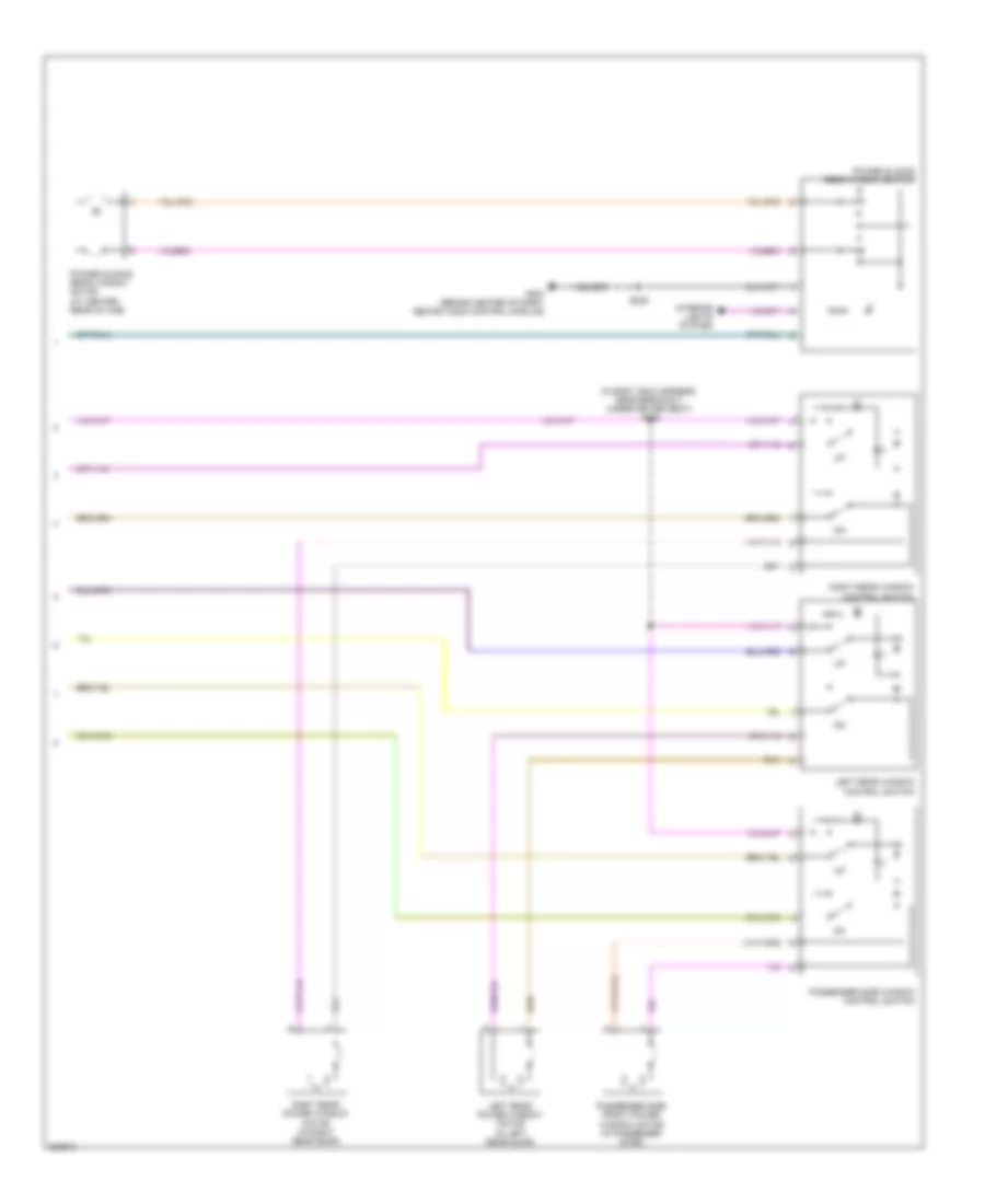 https://portal-diagnostov.com/license.html
Automotive Electricians Portal FZCO
Automotive Electricians Portal FZCO
https://portal-diagnostov.com/license.html
https://portal-diagnostov.com/license.html
Automotive Electricians Portal FZCO
Automotive Electricians Portal FZCOList of elements for Power Windows Wiring Diagram, Crew Cab (2 of 2) for Ford Cab & Chassis F350 Super Duty 2008:
- (in body main harness, near breakout under driver seat) s335
- G203 (behind center of dash, behind audio control module)
- Interior lights system
- Left rear power window motor (in left rear door)
- Left rear window control switch
- Passenger side front power window motor (in passenger door)
- Passenger side window control switch
- Power sliding rear window motor (at center rear of cab)
- Power sliding rear window switch
- Right rear power window motor (in right rear door)
- Right rear window control switch
- S225
Power Windows Wiring Diagram, Except Crew Cab for Ford Cab & Chassis F350 Super Duty 2008
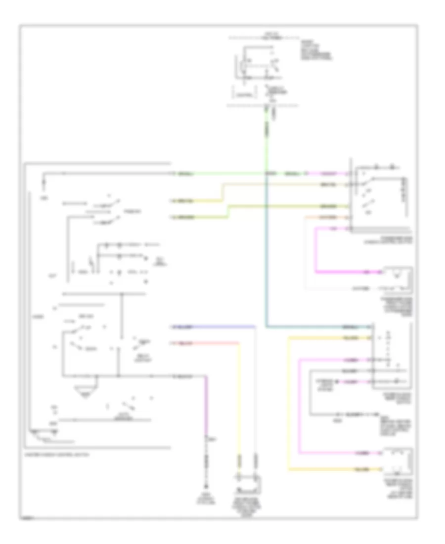 https://portal-diagnostov.com/license.html
Automotive Electricians Portal FZCO
Automotive Electricians Portal FZCO
https://portal-diagnostov.com/license.html
https://portal-diagnostov.com/license.html
Automotive Electricians Portal FZCO
Automotive Electricians Portal FZCOList of elements for Power Windows Wiring Diagram, Except Crew Cab for Ford Cab & Chassis F350 Super Duty 2008:
- Ain
- Amp
- Auto down sw
- C2280d
- Circuit breaker 30a
- Control
- Down
- Driver side front power window motor (in driver door)
- Drv sw
- G203 (behind center of dash, behind audio control module)
- G302 (in right "a" pillar)
- Gnd
- Hot at all times
- Interior lights system
- Master window control switch
- Micro
- Out
- Pass sw
- Passenger side front power window motor (in passenger door)
- Passenger side window control switch
- Power sliding rear window motor (at center rear of cab)
- Power sliding rear window switch
- Relay contact
- Rly coil
- S225
- S303
- S501
- Smart junction box (sjb) (on passenger side kick panel)
- Vdd
- Xin
- Xout
RADIO
Audiophile Sound Radio Wiring Diagram, with DVD (1 of 3) for Ford Cab & Chassis F350 Super Duty 2008
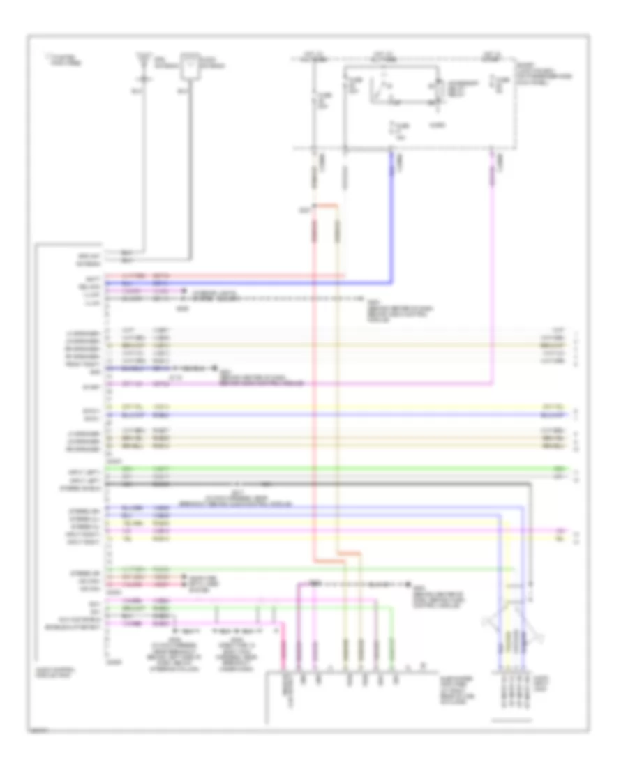 https://portal-diagnostov.com/license.html
Automotive Electricians Portal FZCO
Automotive Electricians Portal FZCO
https://portal-diagnostov.com/license.html
https://portal-diagnostov.com/license.html
Automotive Electricians Portal FZCO
Automotive Electricians Portal FZCOList of elements for Audiophile Sound Radio Wiring Diagram, with DVD (1 of 3) for Ford Cab & Chassis F350 Super Duty 2008:
- Accessory delay relay
- Antenna
- Audio antenna
- Audio control module (acm)
- Audio input jack
- Aux aud shield
- Batt
- C2280a
- C2280b
- C2280d
- C240a
- C240c
- C240d
- Cbp28
- Cbp41
- Computer data lines system
- Del/acc
- Dme22
- Dme45
- Enable/ clip detect
- Enable/clip detect
- Front right-
- Fuse 15a
- Fuse 20a
- Fuse 5a
- G201 (behind center of dash, behind audio control module)
- G202 (behind center of dash, behind audio control module)
- G203 (behind center of dash, behind audio control module)
- Gd114
- Gd115
- Gnd
- Gps ant
- Gps antenna
- Hot at all times
- Hot in start
- Illum+
- Illum-
- Input left+
- Input left-
- Input right+
- Input right-
- Interior lights system
- Lf speaker+
- Lf speaker-
- Lr speaker+
- Lr speaker-
- Micro
- Ms can+
- Ms can-
- Nca
- Pair wires
- Pwr
- Rf speaker+
- Rme07
- Rme09
- Rme10
- Rme12
- Rme17
- Rme18
- Rme22
- Rme24
- Rme45
- Rme46
- Rr speaker+
- Rr speaker-
- S119
- S217 (in main harness, near breakout behind audio control module)
- S225
- S232 (in main harness, near breakout behind left side of dash, below steering column)
- S248 (crew cab: in body main harness, near breakout under dash)
- S321
- S322
- Sbp39
- Smart junction box (on passenger side kick panel)
- Sme23
- St input 2l+
- St input 2l-
- St input 2r+
- St input 2r-
- Start
- Stereo 2l+
- Stereo 2l-
- Stereo 2r+
- Stereo 2r-
- Stereo shield
- Subwoofer amplifier (at right rear of cab, on floor)
- Sw+
- Sw-
- Swc1+
- Swc1-
- Twisted
- Vdb06
- Vdb07
- Vln04
- Vme07
- Vme09
- Vme10
- Vme12
- Vme14
- Vme17
- Vme18
- Vme22
- Vme45
- Vme46
Audiophile Sound Radio Wiring Diagram, with DVD (2 of 3) for Ford Cab & Chassis F350 Super Duty 2008
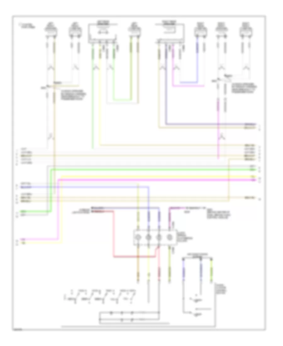 https://portal-diagnostov.com/license.html
Automotive Electricians Portal FZCO
Automotive Electricians Portal FZCO
https://portal-diagnostov.com/license.html
https://portal-diagnostov.com/license.html
Automotive Electricians Portal FZCO
Automotive Electricians Portal FZCOList of elements for Audiophile Sound Radio Wiring Diagram, with DVD (2 of 3) for Ford Cab & Chassis F350 Super Duty 2008:
- (in radio speaker extension harness, near breakout to passenger door)
- Air conditioning system
- Audio/ climate control switch
- C218a
- C218b
- C395a
- C395b
- C396a
- C396b
- Clock spring (in steering column)
- G202 (behind center of dash, behind audio control module)
- Interior lights system
- Left front speaker
- Left front tweeter
- Left rear speaker
- Left rear tweeter
- Media
- Pair wires
- Right front speaker
- Right front tweeter
- Right rear speaker
- Right rear tweeter
- S239
- S502
- S503
- S602
- S603
- Seek+
- Seek-
- Temp+
- Temp-
- Twisted
- Vol+
- Vol-
Audiophile Sound Radio Wiring Diagram, with DVD (3 of 3) for Ford Cab & Chassis F350 Super Duty 2008
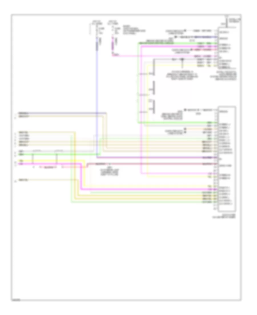 https://portal-diagnostov.com/license.html
Automotive Electricians Portal FZCO
Automotive Electricians Portal FZCO
https://portal-diagnostov.com/license.html
https://portal-diagnostov.com/license.html
Automotive Electricians Portal FZCO
Automotive Electricians Portal FZCOList of elements for Audiophile Sound Radio Wiring Diagram, with DVD (3 of 3) for Ford Cab & Chassis F350 Super Duty 2008:
- (in main harness, in breakout behind right "a" pillar kick panel or behind right side of dash)
- Audio shld
- C2280a
- C2280d
- Computer data lines system
- Dme17
- Drain wire
- Dvd player (on center of inner)
- Fuse 15a
- Fuse 20a
- G201 (behind center of dash, behind audio control module)
- G202 (behind center of dash, behind audio control module)
- Gd114
- Ground
- Hot at all times
- In spkr l+
- In spkr l-
- In spkr r+
- In spkr r-
- Ms can h
- Ms can l
- Nca
- Out spkr l+
- Out spkr l-
- Out spkr r+
- Out spkr r-
- Radio l (+)
- Radio l (-)
- Radio r (+)
- Radio r (-)
- Rme17
- Rme18
- S119
- S203
- S204
- S322
- S901 (in interior lamp harness, near right "c" pillar)
- Satellite antenna
- Satellite digital audio receiver system (sdars) module (behind glove box)
- Sbp40
- Smart junction box (on passenger side kick panel)
- Stereo l+
- Stereo l-
- Stereo r+
- Stereo r-
- Vdb06
- Vdb07
- Vme17
- Vme18
Audiophile Sound Radio Wiring Diagram, without DVD (1 of 2) for Ford Cab & Chassis F350 Super Duty 2008
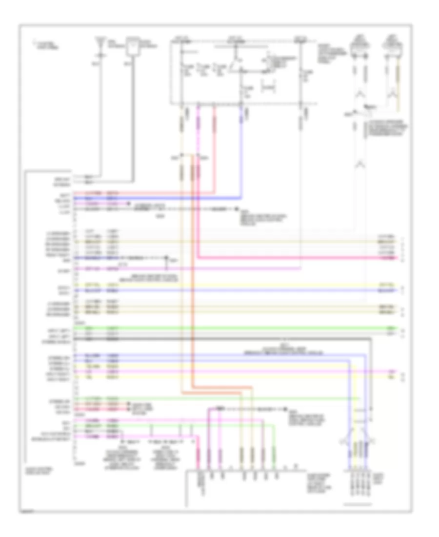 https://portal-diagnostov.com/license.html
Automotive Electricians Portal FZCO
Automotive Electricians Portal FZCO
https://portal-diagnostov.com/license.html
https://portal-diagnostov.com/license.html
Automotive Electricians Portal FZCO
Automotive Electricians Portal FZCOList of elements for Audiophile Sound Radio Wiring Diagram, without DVD (1 of 2) for Ford Cab & Chassis F350 Super Duty 2008:
- (behind center of dash, behind audio control module)
- (in radio speaker extension harness, near breakout to passenger door)
- Accessory delay relay
- Antenna
- Audio antenna
- Audio control module (acm)
- Audio input jack
- Aux aud shield
- Batt
- C2280a
- C2280b
- C2280d
- C240a
- C240c
- C240d
- Cbp28
- Cbp41
- Computer data lines system
- Del/acc
- Dme22
- Dme45
- Enable/ clip detect
- Enable/clip detect
- Front right-
- Fuse 15a
- Fuse 20a
- Fuse 5a
- G201
- G202 (behind center of dash, behind audio control module)
- G203 (behind center of dash, behind audio control module)
- Gd114
- Gd115
- Gnd
- Gps ant
- Gps antenna
- Hot at all times
- Hot in start
- Illum+
- Illum-
- Input left+
- Input left-
- Input right+
- Input right-
- Interior lights system
- Left front speaker
- Left front tweeter
- Lf speaker+
- Lf speaker-
- Lr speaker+
- Lr speaker-
- Micro
- Ms can+
- Ms can-
- Nca
- Pair wires
- Pwr
- Rf speaker+
- Rme07
- Rme09
- Rme10
- Rme12
- Rme17
- Rme18
- Rme22
- Rme24
- Rme45
- Rme46
- Rr speaker+
- Rr speaker-
- S119
- S204
- S217 (in main harness, near breakout behind audio control module)
- S225
- S232 (in main harness, near breakout behind left side of dash, below steering column)
- S248 (crew cab: in body main harness, near breakout under dash)
- S321
- S322
- S502
- S503
- Sbp39
- Smart junction box (on passenger side kick panel)
- Sme23
- St input 2l+
- St input 2l-
- St input 2r+
- St input 2r-
- Start
- Stereo 2l+
- Stereo 2l-
- Stereo 2r+
- Stereo 2r-
- Stereo shield
- Subwoofer amplifier (at right rear of cab, on floor)
- Sw+
- Sw-
- Swc1+
- Swc1-
- Twisted
- Vdb06
- Vdb07
- Vln04
- Vme07
- Vme09
- Vme10
- Vme12
- Vme14
- Vme17
- Vme18
- Vme22
- Vme45
- Vme46
Audiophile Sound Radio Wiring Diagram, without DVD (2 of 2) for Ford Cab & Chassis F350 Super Duty 2008
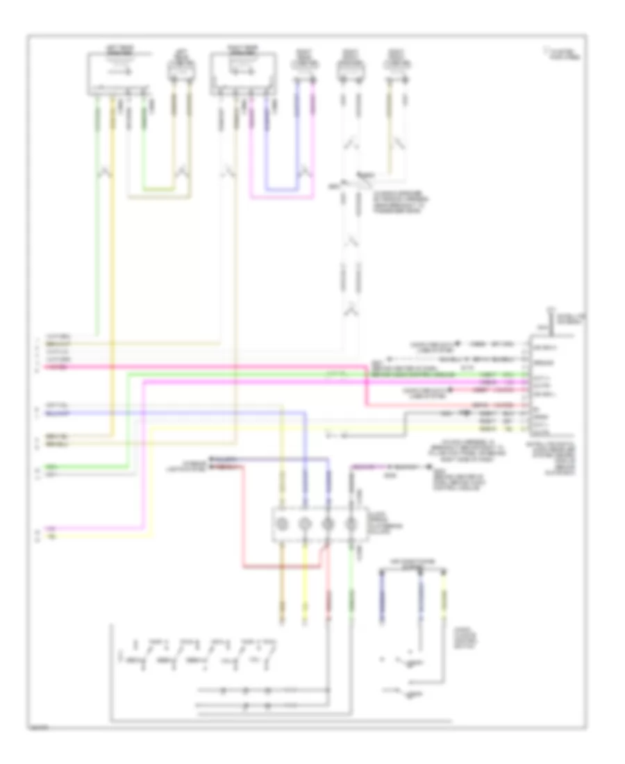 https://portal-diagnostov.com/license.html
Automotive Electricians Portal FZCO
Automotive Electricians Portal FZCO
https://portal-diagnostov.com/license.html
https://portal-diagnostov.com/license.html
Automotive Electricians Portal FZCO
Automotive Electricians Portal FZCOList of elements for Audiophile Sound Radio Wiring Diagram, without DVD (2 of 2) for Ford Cab & Chassis F350 Super Duty 2008:
- (in main harness, in breakout behind right "a" pillar kick panel or behind right side of dash)
- (in radio speaker extension harness, near breakout to passenger door)
- Air conditioning system
- Audio/ climate control switch
- C218a
- C218b
- C395a
- C395b
- C396a
- C396b
- Clock spring (in steering column)
- Computer data lines system
- Dme17
- Drain
- G201 (behind center of dash, behind audio control module)
- G202 (behind center of dash, behind audio control module)
- Gd114
- Ground
- Interior lights system
- Left rear speaker
- Left rear tweeter
- Media
- Ms can h
- Ms can l
- Nca
- Out l+
- Out l-
- Out r+
- Out r-
- Pair wires
- Right front speaker
- Right front tweeter
- Right rear speaker
- Right rear tweeter
- Rme17
- Rme18
- S119
- S239
- S352
- S602
- S603
- Satellite antenna
- Satellite digital audio receiver system (sdars) module (behind glove box)
- Sbp40
- Seek+
- Seek-
- Temp+
- Temp-
- Twisted
- Vdb06
- Vdb07
- Vme17
- Vme18
- Vol+
- Vol-
Base Radio Wiring Diagram for Ford Cab & Chassis F350 Super Duty 2008
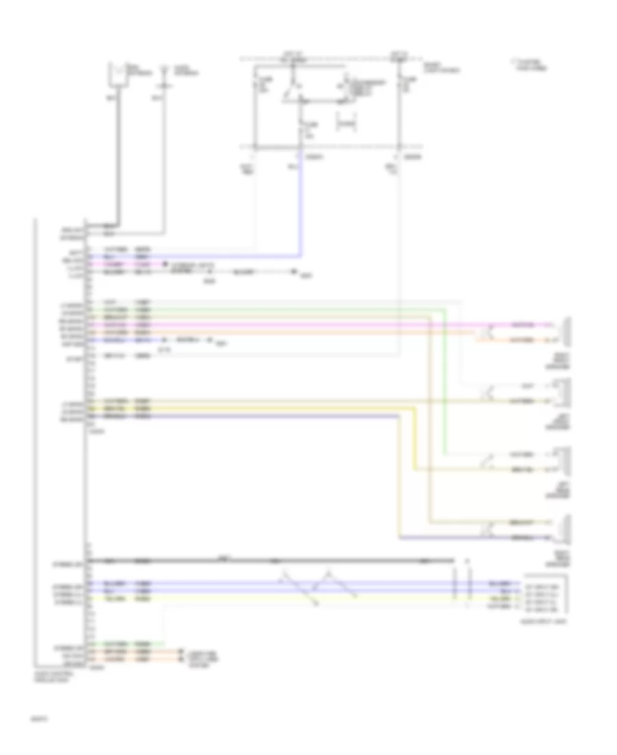 https://portal-diagnostov.com/license.html
Automotive Electricians Portal FZCO
Automotive Electricians Portal FZCO
https://portal-diagnostov.com/license.html
https://portal-diagnostov.com/license.html
Automotive Electricians Portal FZCO
Automotive Electricians Portal FZCOList of elements for Base Radio Wiring Diagram for Ford Cab & Chassis F350 Super Duty 2008:
- Accessory delay relay
- Amp gnd
- Antenna
- Audio antenna
- Audio control module (acm)
- Audio input jack
- Batt
- C2280a
- C2280b
- C240a
- C240c
- Cbp28
- Cbp41
- Computer data lines system
- Del/acc
- Dme45
- Fuse 15a
- Fuse 20a
- Fuse 5a
- G201
- G203
- Gd114
- Gd115
- Gps ant
- Gps antenna
- Hot at all times
- Hot in start
- Illum+
- Illum-
- Interior lights system
- Left front speaker
- Left rear speaker
- Lf spkr+
- Lf spkr-
- Lr spkr-
- Micro
- Ms can+
- Ms can-
- Nca
- Pair wires
- Rf spkr+
- Rf spkr-
- Right front speaker
- Right rear speaker
- Rme07
- Rme09
- Rme10
- Rme12
- Rme45
- Rme46
- Rr spkr+
- Rr spkr-
- S119
- S217
- S225
- Sbp39
- Smart junction box
- St input 2l+
- St input 2l-
- St input 2r+
- St input 2r-
- Start
- Stereo 2l+
- Stereo 2l-
- Stereo 2r+
- Stereo 2r-
- Twisted
- Vdb06
- Vdb07
- Vln04
- Vme07
- Vme09
- Vme10
- Vme12
- Vme45
- Vme46
SHIFT INTERLOCK
Shift Interlock Wiring Diagram for Ford Cab & Chassis F350 Super Duty 2008
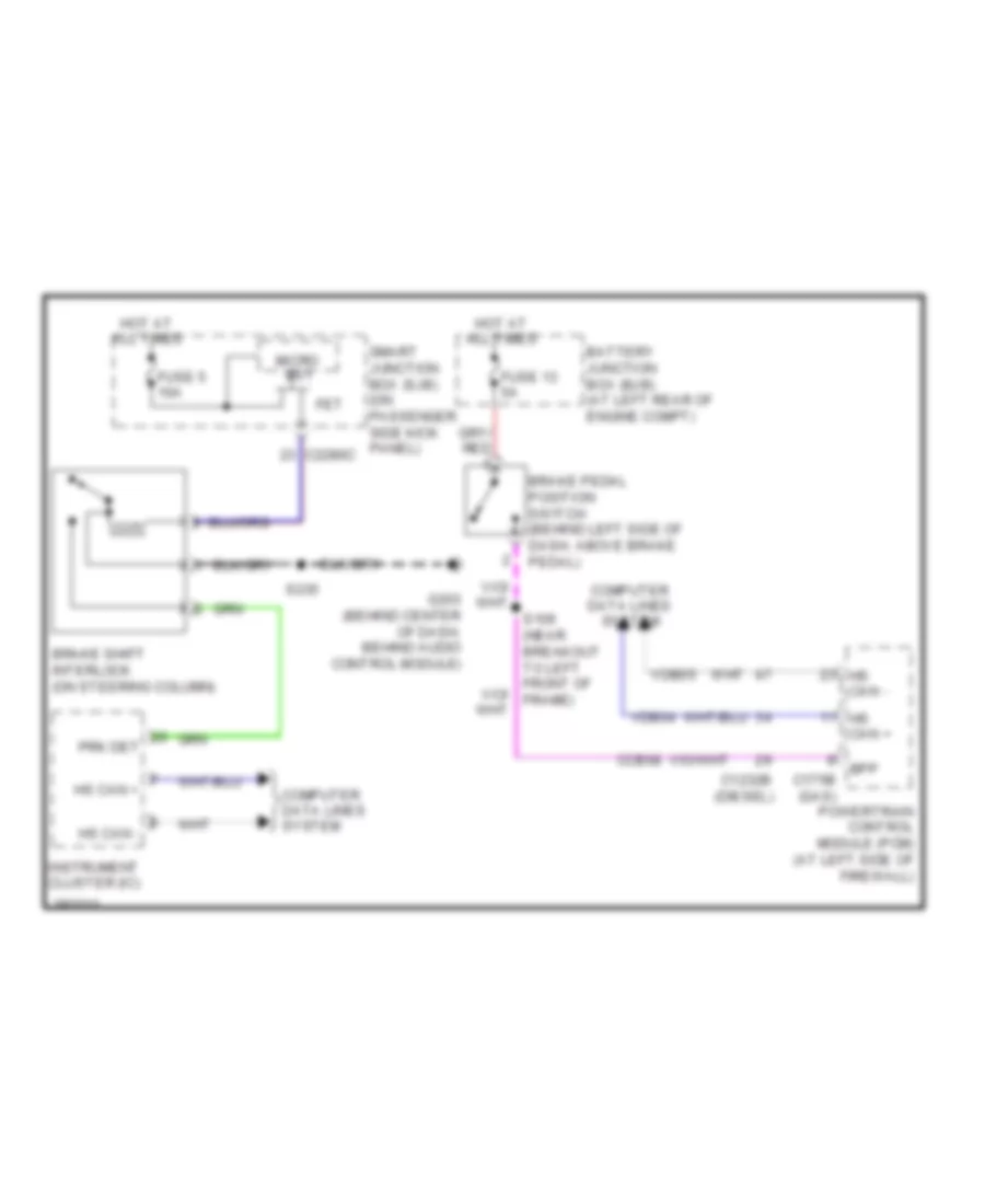 https://portal-diagnostov.com/license.html
Automotive Electricians Portal FZCO
Automotive Electricians Portal FZCO
https://portal-diagnostov.com/license.html
https://portal-diagnostov.com/license.html
Automotive Electricians Portal FZCO
Automotive Electricians Portal FZCOList of elements for Shift Interlock Wiring Diagram for Ford Cab & Chassis F350 Super Duty 2008:
- Battery junction box (bjb) (at left rear of engine compt)
- Bpp
- Brake pedal position switch (behind left side of dash, above brake pedal)
- Brake shift interlock (on steering column)
- C1232b (diesel)
- C175b (gas)
- C2280c
- Ccb08
- Computer data lines system
- Fet
- Fuse 13 5a
- Fuse 5 10a
- G203 (behind center of dash, behind audio control module)
- Hot at all times
- Hs can +
- Hs can -
- Instrument cluster (ic)
- Micro bs1
- Powertrain control module (pcm) (at left side of firewall)
- Prk det
- S106 (near breakout to left front of frame)
- S235
- Smart junction box (sjb) (on passenger side kick panel)
- Vdb04
- Vdb05
STARTING/CHARGING
5.4L
5.4L, Charging Wiring Diagram for Ford Cab & Chassis F350 Super Duty 2008
 https://portal-diagnostov.com/license.html
Automotive Electricians Portal FZCO
Automotive Electricians Portal FZCO
https://portal-diagnostov.com/license.html
https://portal-diagnostov.com/license.html
Automotive Electricians Portal FZCO
Automotive Electricians Portal FZCOList of elements for 5.4L, Charging Wiring Diagram for Ford Cab & Chassis F350 Super Duty 2008:
- Battery
- Battery junction box (bjb) (at left rear of engine compt)
- C102a
- C102b
- C175b
- C175e
- Cbb71
- Cdc09
- Computer data lines system
- Fuse 5a
- G100 (on right front inner fender, near battery)
- G101 (5.4l: at rear left side of engine, on bottom) (6.8l: at rear right side of engine, on bottom)
- G102 (5.4l: at front right side of engine, on bottom) (6.8l: at right front of engine compt, under battery)
- Generator
- Hot in run or start
- Hscan bus+
- Hscan bus-
- Ilc
- Isp-r
- Power distribution system
- Powertrain control module (pcm) (at left side of firewall)
- Red
- S123
- S137
- S138
- S139
- Starting circuit
- Vdbo4
- Vdbo5
5.4L, Starting Wiring Diagram for Ford Cab & Chassis F350 Super Duty 2008
 https://portal-diagnostov.com/license.html
Automotive Electricians Portal FZCO
Automotive Electricians Portal FZCO
https://portal-diagnostov.com/license.html
https://portal-diagnostov.com/license.html
Automotive Electricians Portal FZCO
Automotive Electricians Portal FZCOList of elements for 5.4L, Starting Wiring Diagram for Ford Cab & Chassis F350 Super Duty 2008:
- (6.8l: at rear right side of engine, on bottom) (5.4l: at rear left side of engine, on bottom) g101
- (6.8l: under battery)
- (at left rear of engine compt) battery junction box (bjb)
- Acc
- Batt
- Battery
- Battery junction box (bjb) (at left rear of engine compt)
- C175b
- C175t
- C281a
- Cdc12
- Cdc35
- Cdc38
- Ce903
- Ce904
- Cet21
- Circuit deactivation ignition module (cdim) (behind left side of dash)
- Cls05
- Clutch pedal position switch (m/t) (behind left side of dash, above clutch pedal)
- Cpp bt
- Cpp tt
- Crank
- Early production
- Four-wheel drive control module (behind right side of dash)
- Fuse 20a
- Fuse 40 30a
- G100 (on right front inner fender, near battery)
- G102 (5.4l: at front right side of engine, on bottom)
- Hot at all times
- Ignition switch
- Late production
- Lock
- Neutral
- Otis diode
- Out
- Park
- Power distribution system
- Powertrain control module (pcm) (at left side of firewall)
- Red
- Run
- S126
- S157
- S162
- Se/smc
- Smart junction box (sjb) (on passenger side kick panel)
- Smr/ start
- Start
- Starter motor
- Starter relay
- W/ cdim
6.4L DIESEL
6.4L Diesel, Charging Wiring Diagram for Ford Cab & Chassis F350 Super Duty 2008
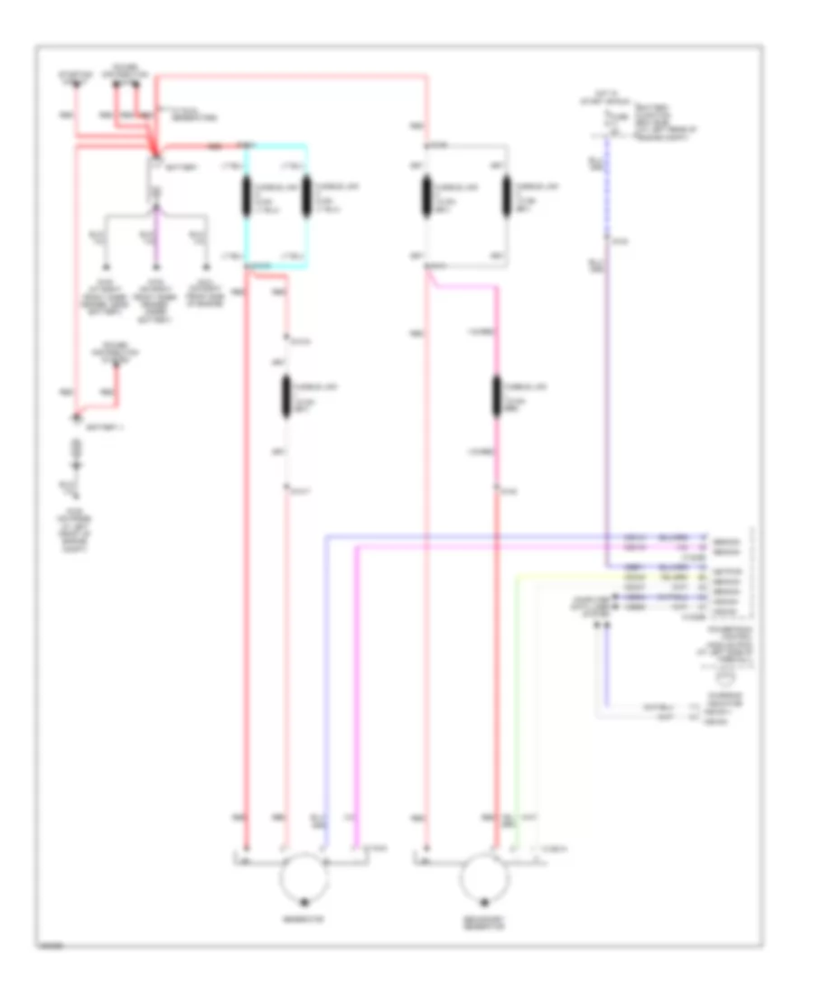 https://portal-diagnostov.com/license.html
Automotive Electricians Portal FZCO
Automotive Electricians Portal FZCO
https://portal-diagnostov.com/license.html
https://portal-diagnostov.com/license.html
Automotive Electricians Portal FZCO
Automotive Electricians Portal FZCOList of elements for 6.4L Diesel, Charging Wiring Diagram for Ford Cab & Chassis F350 Super Duty 2008:
- Battery
- Battery ii
- Battery junction box (bjb) (at left rear of engine compt)
- C1104a
- C1232b
- C1232e
- C1251a
- Cbb71
- Cdc10
- Cdc15
- Cdc47
- Cdc48
- Charging indicator
- Computer data lines system
- Fuse 5a
- G100 (at right front inner fender, near battery)
- G101 (on right front side of engine)
- G102 (on right front inner fender, under battery)
- G109 (on frame, at left front of engine compt)
- Gencon
- Generator
- Genmon
- Hot in start or run
- Hscan +
- Hscan+
- Hscan-
- Keypwr
- Power distribution system
- Powertrain control module (pcm) (at left side of firewall)
- Red
- S1014
- S1015
- S1016
- S1017
- S123
- S139
- S140
- S141
- Secondary generator
- Starting circuit
- Vdb04
- Vdb05
- W/ dual generators
6.4L Diesel, Starting Wiring Diagram, Early Production for Ford Cab & Chassis F350 Super Duty 2008
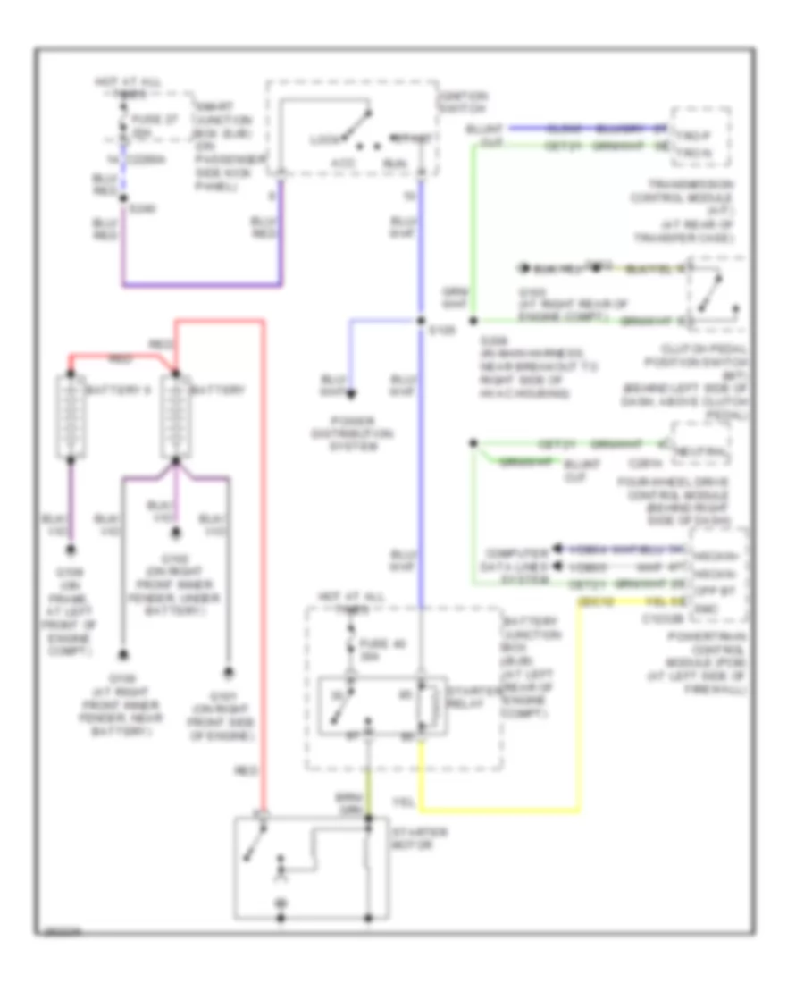 https://portal-diagnostov.com/license.html
Automotive Electricians Portal FZCO
Automotive Electricians Portal FZCO
https://portal-diagnostov.com/license.html
https://portal-diagnostov.com/license.html
Automotive Electricians Portal FZCO
Automotive Electricians Portal FZCOList of elements for 6.4L Diesel, Starting Wiring Diagram, Early Production for Ford Cab & Chassis F350 Super Duty 2008:
- (at rear of transfer case)
- Acc
- Battery
- Battery ii
- Battery junction box (bjb) (at left rear of engine compt)
- C1232b
- C2280a
- C281a
- Cdc12
- Cet21
- Cls05
- Clutch pedal position switch (m/t) (behind left side of dash, above clutch pedal)
- Computer data lines system
- Cpp bt
- Four-wheel drive control module (behind right side of dash)
- Fuse 27 20a
- Fuse 40 30a
- G100 (at right front inner fender, near battery)
- G101 (on right front side of engine)
- G102 (on right front inner fender, under battery)
- G103 (at right rear of engine compt)
- G109 (on frame, at left front of engine compt)
- Hot at all times
- Hscan+
- Hscan-
- Ignition switch
- Lock
- Neutral
- Power distribution system
- Powertrain control module (pcm) (at left side of firewall)
- Red
- Run
- S126
- S162
- S208 (in main harness, near breakout to right side of hvac housing)
- S240
- Smart junction box (sjb) (on passenger side kick panel)
- Smc
- Start
- Starter motor
- Starter relay
- Transmission control module (a/t)
- Tro n
- Tro p
- Vdb04
- Vdb05
6.4L Diesel, Starting Wiring Diagram, Late Production for Ford Cab & Chassis F350 Super Duty 2008
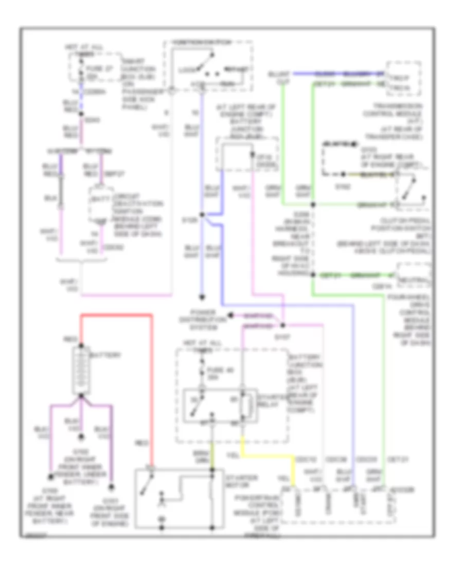 https://portal-diagnostov.com/license.html
Automotive Electricians Portal FZCO
Automotive Electricians Portal FZCO
https://portal-diagnostov.com/license.html
https://portal-diagnostov.com/license.html
Automotive Electricians Portal FZCO
Automotive Electricians Portal FZCOList of elements for 6.4L Diesel, Starting Wiring Diagram, Late Production for Ford Cab & Chassis F350 Super Duty 2008:
- (at left rear of engine compt) battery junction box (bjb)
- (at rear of transfer case)
- Acc
- Batt
- Battery
- Battery junction box (bjb) (at left rear of engine compt)
- C1232b
- C2280a
- C281a
- Cdc12
- Cdc35
- Cdc38
- Cet21
- Circuit deactivation ignition module (cdim) (behind left side of dash)
- Cls05
- Clutch pedal position switch (m/t) (behind left side of dash, above clutch pedal)
- Cpp bt
- Crank
- Four-wheel drive control module (behind right side of dash)
- Fuse 27 20a
- Fuse 40 30a
- G100 (at right front inner fender, near battery)
- G101 (on right front side of engine)
- G102 (on right front inner fender, under battery)
- G103 (at right rear of engine compt)
- Hot at all times
- Ignition switch
- Lock
- Neutral
- Otis diode
- Out
- Power distribution system
- Powertrain control module (pcm) (at left side of firewall)
- Red
- Run
- S126
- S157
- S162
- S208 (in main harness, near breakout to right side of hvac housing)
- S240
- Se/smc
- Smart junction box (sjb) (on passenger side kick panel)
- Smr/ start
- Start
- Starter motor
- Starter relay
- Transmission control module (a/t)
- Tro n
- Tro p
- W/ cdim
- W/o cdim
6.8L
6.8L, Charging Wiring Diagram for Ford Cab & Chassis F350 Super Duty 2008
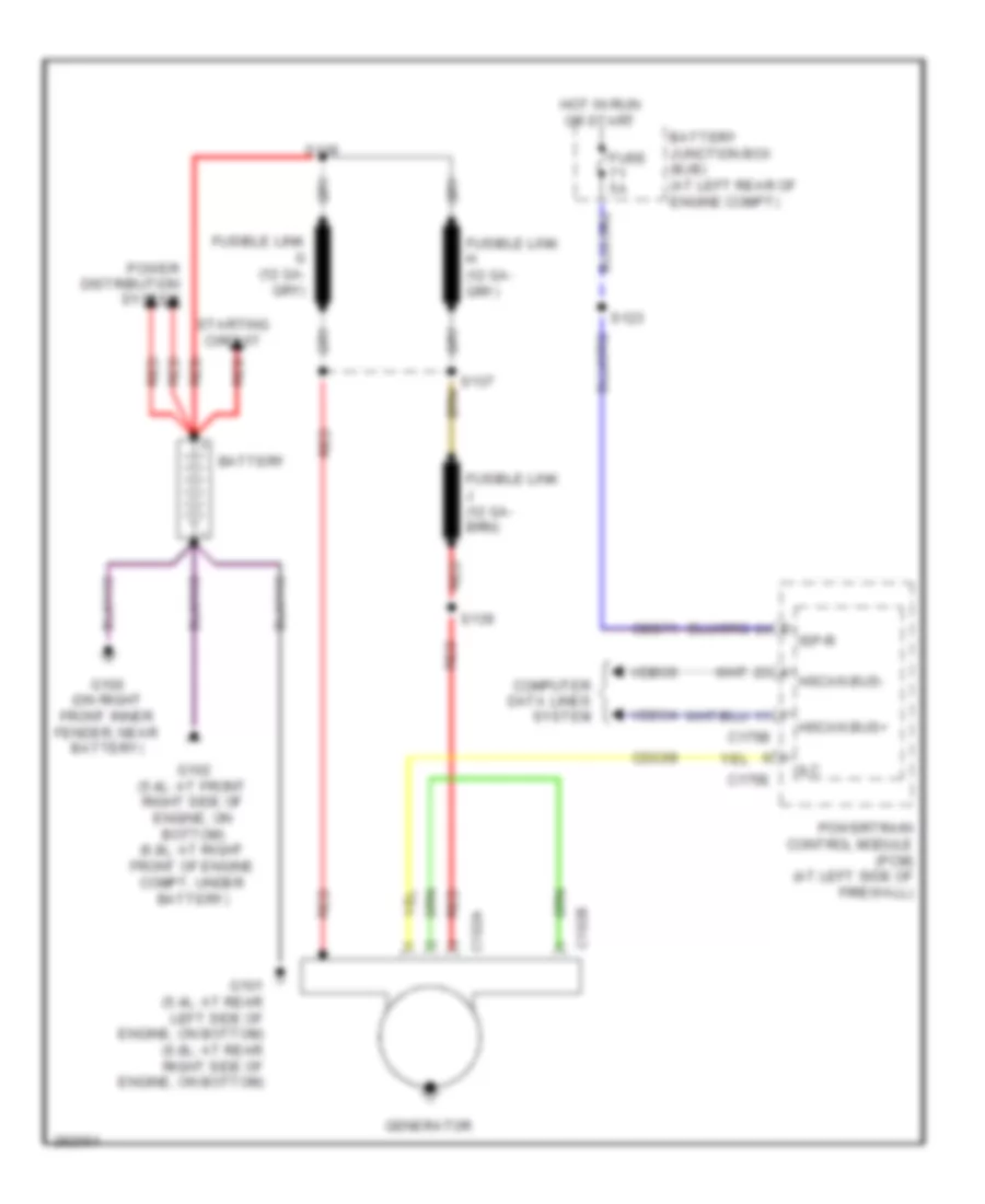 https://portal-diagnostov.com/license.html
Automotive Electricians Portal FZCO
Automotive Electricians Portal FZCO
https://portal-diagnostov.com/license.html
https://portal-diagnostov.com/license.html
Automotive Electricians Portal FZCO
Automotive Electricians Portal FZCOList of elements for 6.8L, Charging Wiring Diagram for Ford Cab & Chassis F350 Super Duty 2008:
- Battery
- Battery junction box (bjb) (at left rear of engine compt)
- C102a
- C102b
- C175b
- C175e
- Cbb71
- Cdc09
- Computer data lines system
- Fuse 5a
- G100 (on right front inner fender, near battery)
- G101 (5.4l: at rear left side of engine, on bottom) (6.8l: at rear right side of engine, on bottom)
- G102 (5.4l: at front right side of engine, on bottom) (6.8l: at right front of engine compt, under battery)
- Generator
- Hot in run or start
- Hscan bus+
- Hscan bus-
- Ilc
- Isp-r
- Power distribution system
- Powertrain control module (pcm) (at left side of firewall)
- Red
- S123
- S137
- S138
- S139
- Starting circuit
- Vdbo4
- Vdbo5
6.8L, Starting Wiring Diagram for Ford Cab & Chassis F350 Super Duty 2008
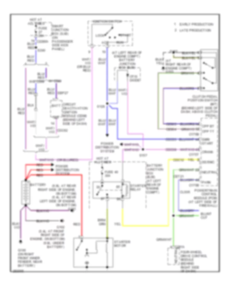 https://portal-diagnostov.com/license.html
Automotive Electricians Portal FZCO
Automotive Electricians Portal FZCO
https://portal-diagnostov.com/license.html
https://portal-diagnostov.com/license.html
Automotive Electricians Portal FZCO
Automotive Electricians Portal FZCOList of elements for 6.8L, Starting Wiring Diagram for Ford Cab & Chassis F350 Super Duty 2008:
- (6.8l: at rear right side of engine, on bottom) (5.4l: at rear left side of engine, on bottom) g101
- (6.8l: under battery)
- (at left rear of engine compt) battery junction box (bjb)
- Acc
- Batt
- Battery
- Battery junction box (bjb) (at left rear of engine compt)
- C175b
- C175t
- C281a
- Cdc12
- Cdc35
- Cdc38
- Ce903
- Ce904
- Cet21
- Circuit deactivation ignition module (cdim) (behind left side of dash)
- Cls05
- Clutch pedal position switch (m/t) (behind left side of dash, above clutch pedal)
- Cpp bt
- Cpp tt
- Crank
- Early production
- Four-wheel drive control module (behind right side of dash)
- Fuse 20a
- Fuse 40 30a
- G100 (on right front inner fender, near battery)
- G102 (5.4l: at front right side of engine, on bottom)
- Hot at all times
- Ignition switch
- Late production
- Lock
- Neutral
- Otis diode
- Out
- Park
- Power distribution system
- Powertrain control module (pcm) (at left side of firewall)
- Red
- Run
- S126
- S157
- S162
- Se/smc
- Smart junction box (sjb) (on passenger side kick panel)
- Smr/ start
- Start
- Starter motor
- Starter relay
- W/ cdim
SUPPLEMENTAL RESTRAINTS
Supplemental Restraints Wiring Diagram for Ford Cab & Chassis F350 Super Duty 2008
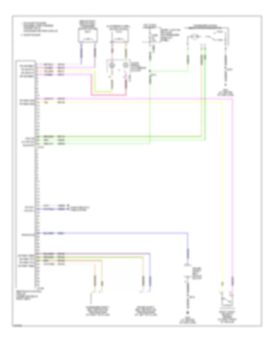 https://portal-diagnostov.com/license.html
Automotive Electricians Portal FZCO
Automotive Electricians Portal FZCO
https://portal-diagnostov.com/license.html
https://portal-diagnostov.com/license.html
Automotive Electricians Portal FZCO
Automotive Electricians Portal FZCOList of elements for Supplemental Restraints Wiring Diagram for Ford Cab & Chassis F350 Super Duty 2008:
- (behind right side of dash) passenger air bag igniter
- (in steering wheel) driver air bag
- C218a
- C2280d
- C310a
- C310b
- Cbp32
- Clock- spring (in steering column)
- Computer data lines system
- Cr101
- Cr103
- Cr120
- Cr122
- Cr139
- Cr201
- Cr224
- Cutoff sw
- Dr ab feed1
- Dr ab rtn1
- Dr buckle
- Dr pret feed
- Dr pret rtn
- Driver safety belt buckle switch
- Driver safety belt retractor pretensioner (at left "b" pillar)
- Engaged when harness connector is disconnected from module
- Fr crsh sns
- Front impact severity sensor (at right front of vehicle)
- Fuse 10a
- G303 (at center of cab floor)
- Hot in run or start
- Hs can +
- Hs can -
- Pad ind
- Passenger air bag deactivation (pad) switch
- Passenger safety belt retractor pretensioner (at right "b" pillar)
- Pin shorting bars
- Ps ab feed1
- Ps ab rtn1
- Ps pret feed
- Ps pret rtn
- Red
- Restraints control module (under center of front seat)
- Rr101
- Rr103
- Rr116
- Rr120
- Rr122
- Rr139
- Run/strt
- S316
- Shorting bar
- Smart junction box (sjb) (on passenger side kick panel)
- Vdb04
- Vdb05
TRANSMISSION
4WD Wiring Diagram for Ford Cab & Chassis F350 Super Duty 2008
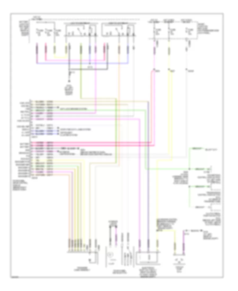 https://portal-diagnostov.com/license.html
Automotive Electricians Portal FZCO
Automotive Electricians Portal FZCO
https://portal-diagnostov.com/license.html
https://portal-diagnostov.com/license.html
Automotive Electricians Portal FZCO
Automotive Electricians Portal FZCOList of elements for 4WD Wiring Diagram for Ford Cab & Chassis F350 Super Duty 2008:
- (in engine control sensor harness, in breakout to left rear of engine compt) s105
- 2h to 4l
- 4h lamp
- 4l lamp
- 4l to 2h
- 87a
- Anti-lock brakes system
- Battery
- Battery junction box (bjb) (at left rear of engine compt)
- Brake sw
- C175b
- C2280a
- C2280b
- C281a
- C281b
- C350a
- C350b
- Cbp35
- Cbp43
- Ccb08
- Ccf06
- Ccf13
- Ccf14
- Ccf15
- Ccf16
- Ccf17
- Ccf22
- Ccf25
- Ccf26
- Ccf27
- Ccf28
- Cet21
- Clutch pedal position switch (6.4l) (behind left side of dash, above clutch pedal)
- Computer data lines system
- Electronic shift on the fly (esof) solenoid (at right side of engine compt)
- Encoder a
- Encoder b
- Encoder c
- Encoder p
- Encoder pwr
- Encoder ref
- Exterior lights system
- Four-wheel drive control module (behind right side of dash)
- Four-wheel drive switch
- Fuse 10a
- Fuse 20a
- Fuse 30a
- Fuse 5a
- G104 (at left rear of engine compt)
- G108 (at left rear of engine compt)
- G203 (behind center of dash, behind audio control module)
- Gd115
- Gnd
- High to low relay
- Hot at all times
- Hot in run or acc
- Hot in run or start
- Hub lock
- Hub unlock
- Illum
- Instrument cluster system
- Interior lights system
- Iso9141
- Lcf24
- Low to high relay
- Mod sel
- Mod sel ref
- Neutral
- Off
- Powertrain control module (pcm) (at left side of firewall)
- R s
- Rcf09
- Rcf13
- Run/acc
- S115
- S118
- S204
- S208 (in main harness, near breakout to right side of hvac housing)
- S225
- S227
- S2439
- Sbp40
- Smart junction box (sjb) (on passenger side kick panel)
- Transfer case assembly
- Transmission control module (tcm) (6.4l) (at rear of transfer case)
- Vacuum pump (6.4l)
- Vdb10
- Ve822
- Vss
5.4L
5.4L, A/T Wiring Diagram for Ford Cab & Chassis F350 Super Duty 2008
 https://portal-diagnostov.com/license.html
Automotive Electricians Portal FZCO
Automotive Electricians Portal FZCO
https://portal-diagnostov.com/license.html
https://portal-diagnostov.com/license.html
Automotive Electricians Portal FZCO
Automotive Electricians Portal FZCOList of elements for 5.4L, A/T Wiring Diagram for Ford Cab & Chassis F350 Super Duty 2008:
- (in backup lamp switch to rear lamp feed harness, near breakout to front left side of transmission, near top)
- (sspc-a) control a pressure solenoid shift
- (sspc-b) control b pressure solenoid shift
- (sspc-c) control c pressure solenoid shift
- (sspc-d) control d pressure solenoid shift
- (sspc-e) control e pressure solenoid shift
- (tr-p) assembly sensor range transmission
- Bps
- Brake pressure switch (at bottom of master cylinder)
- C175b
- C175e
- C175t
- C2280b
- Cat15
- Ces09
- Cet05
- Cet06
- Cet07
- Cet08
- Cet09
- Cet22
- Cet25
- Cet49
- Cet50
- Computer data lines system
- Fuse 10a
- Hot in run or start
- Hs can (+)
- Hs can (-)
- Instrument cluster (ic)
- Iss
- Le111
- Nca
- O/d off indicator
- O/d off switch (at top of steering column)
- Oss
- Output shaft speed (oss) sensor (at top of transmission extension housing)
- Pca
- Powertrain control module (pcm) (at left side of firewall)
- Re406
- Ret04
- Ret24
- S183
- S194
- S196
- S227
- Sensor temperature fluid transmission
- Sig rtn
- Smart junction box (sjb) (on passenger side kick panel)
- Solenoid (pc-a) control pressure
- Solenoid clutch converter torque
- Speed sensor assembly (at top left side of transmission)
- Sspc a
- Sspc b
- Sspc c
- Sspc d
- Sspc e
- T sig rtn
- Tcc
- Tcs
- Tft
- Transmission torqshift
- Trp
- Tss
- Vbpwr
- Ve733
- Ve744
- Vet27
- Vpwr
6.4L DIESEL
6.4L Diesel, A/T Wiring Diagram for Ford Cab & Chassis F350 Super Duty 2008
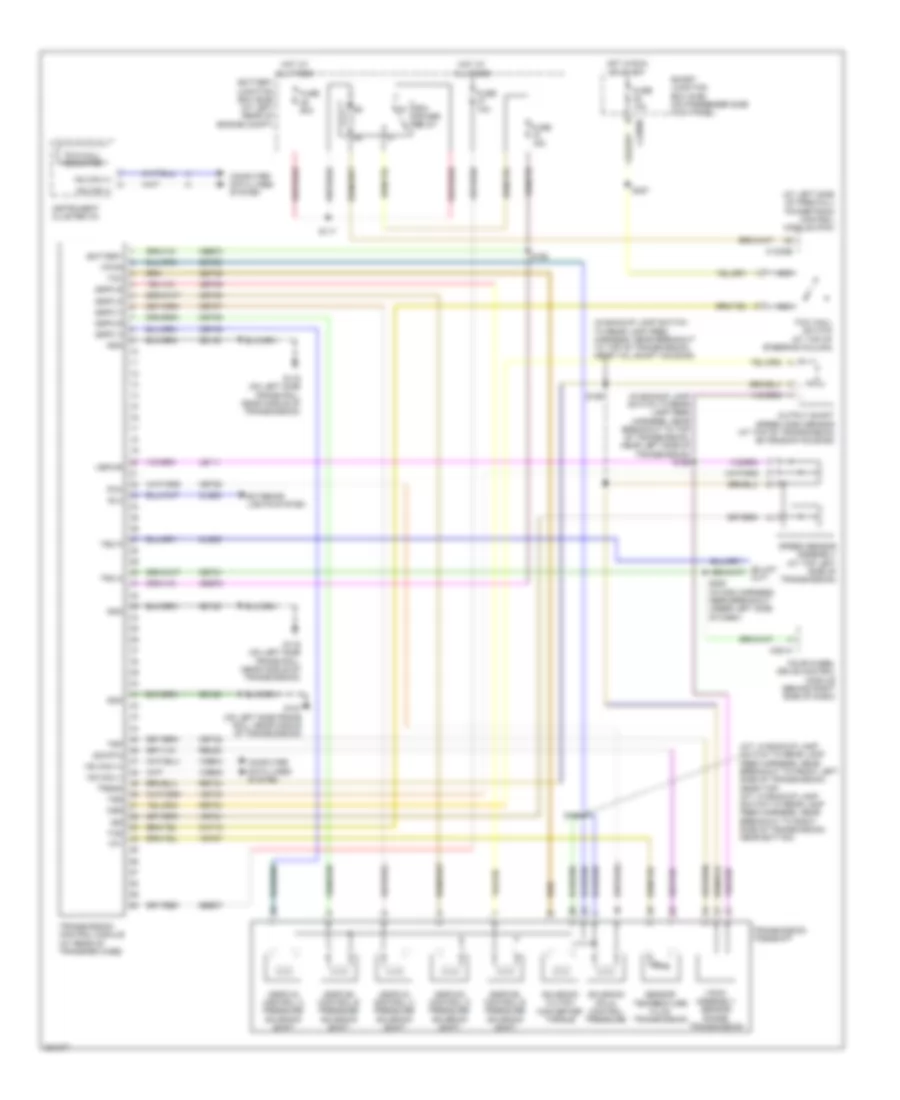 https://portal-diagnostov.com/license.html
Automotive Electricians Portal FZCO
Automotive Electricians Portal FZCO
https://portal-diagnostov.com/license.html
https://portal-diagnostov.com/license.html
Automotive Electricians Portal FZCO
Automotive Electricians Portal FZCOList of elements for 6.4L Diesel, A/T Wiring Diagram for Ford Cab & Chassis F350 Super Duty 2008:
- (a/t: in backup lamp switch to rear lamp feed harness, near breakout to front left side of transmission, near top) (m/t: in backup lamp switch to rear lamp feed harness, near breakout to right side of transmission, near bottom)
- (at left side of firewall) powertrain control module (pcm)
- (in backup lamp switch to rear lamp feed harness, near breakout to top of transmission, near left side of transmission) s196
- (in backup lamp switch to rear lamp feed harness, near breakout to top of transmission, near tail shaft housing)
- (sspc-a) control a pressure solenoid shift
- (sspc-b) control b pressure solenoid shift
- (sspc-c) control c pressure solenoid shift
- (sspc-d) control d pressure solenoid shift
- (sspc-e) control e pressure solenoid shift
- (tr-p) assembly sensor range transmission
- Battery
- Battery junction box (bjb) (at left rear of engine compt)
- C1232b
- C2280b
- C281a
- Cat15
- Cbb72
- Cet05
- Cet06
- Cet07
- Cet09
- Cet21
- Cet22
- Cet25
- Cet49
- Cet50
- Cls05
- Cls28
- Computer data lines system
- Exterior lights system
- Four-wheel drive control module (behind right side of dash)
- Fuse 10a
- Fuse 15a
- Fuse 50a
- G107 (on left side frame rail, near middle of transmission)
- G116 (on left side frame rail, near middle of transmission)
- Gd120
- Gnd
- Hot at all times
- Hot in run or start
- Hs can (+)
- Hs can (-)
- Instrument cluster (ic)
- Iss
- Le111
- Nca
- Oss
- Output shaft speed (oss) sensor (at top of transmission extension housing)
- Pca
- Pcm power relay
- Re406
- Ret04
- Ret24
- Rlc
- S117
- S192
- S194
- S198
- S208 (in main harness, near breakout under left side of dash)
- S227
- Sbb37
- Sensor temperature fluid transmission
- Sig rtn
- Smart junction box (sjb) (on passenger side kick panel)
- Solenoid (pc-a) control pressure
- Solenoid clutch converter torque
- Speed sensor assembly (at top left side of transmission)
- Sspc a
- Sspc b
- Sspc c
- Sspc d
- Sspc e
- Tcc
- Tcs
- Tft
- Tow haul switch (at top of steering column)
- Tow/haul indicator
- Transmission control module (at rear of transfer case)
- Transmission torqshift
- Trgnd
- Tro n
- Tro p
- Trp
- Tss
- Vbpwr
- Vdb04
- Vdb05
- Ve744
- Vet27
- Vet33
- Vpwr
6.8L
6.8L, A/T Wiring Diagram for Ford Cab & Chassis F350 Super Duty 2008
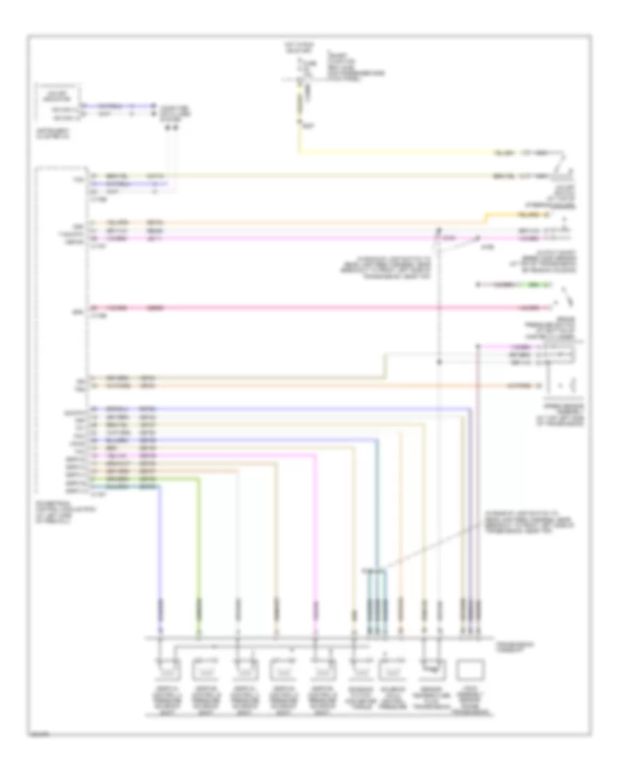 https://portal-diagnostov.com/license.html
Automotive Electricians Portal FZCO
Automotive Electricians Portal FZCO
https://portal-diagnostov.com/license.html
https://portal-diagnostov.com/license.html
Automotive Electricians Portal FZCO
Automotive Electricians Portal FZCOList of elements for 6.8L, A/T Wiring Diagram for Ford Cab & Chassis F350 Super Duty 2008:
- (in backup lamp switch to rear lamp feed harness, near breakout to front left side of transmission, near top)
- (sspc-a) control a pressure solenoid shift
- (sspc-b) control b pressure solenoid shift
- (sspc-c) control c pressure solenoid shift
- (sspc-d) control d pressure solenoid shift
- (sspc-e) control e pressure solenoid shift
- (tr-p) assembly sensor range transmission
- Bps
- Brake pressure switch (at bottom of master cylinder)
- C175b
- C175e
- C175t
- C2280b
- Cat15
- Ces09
- Cet05
- Cet06
- Cet07
- Cet08
- Cet09
- Cet22
- Cet25
- Cet49
- Cet50
- Computer data lines system
- Fuse 10a
- Hot in run or start
- Hs can (+)
- Hs can (-)
- Instrument cluster (ic)
- Iss
- Le111
- Nca
- O/d off indicator
- O/d off switch (at top of steering column)
- Oss
- Output shaft speed (oss) sensor (at top of transmission extension housing)
- Pca
- Powertrain control module (pcm) (at left side of firewall)
- Re406
- Ret04
- Ret24
- S183
- S194
- S196
- S227
- Sensor temperature fluid transmission
- Sig rtn
- Smart junction box (sjb) (on passenger side kick panel)
- Solenoid (pc-a) control pressure
- Solenoid clutch converter torque
- Speed sensor assembly (at top left side of transmission)
- Sspc a
- Sspc b
- Sspc c
- Sspc d
- Sspc e
- T sig rtn
- Tcc
- Tcs
- Tft
- Transmission torqshift
- Trp
- Tss
- Vbpwr
- Ve733
- Ve744
- Vet27
- Vpwr
WARNING SYSTEMS
Warning Systems Wiring Diagram for Ford Cab & Chassis F350 Super Duty 2008
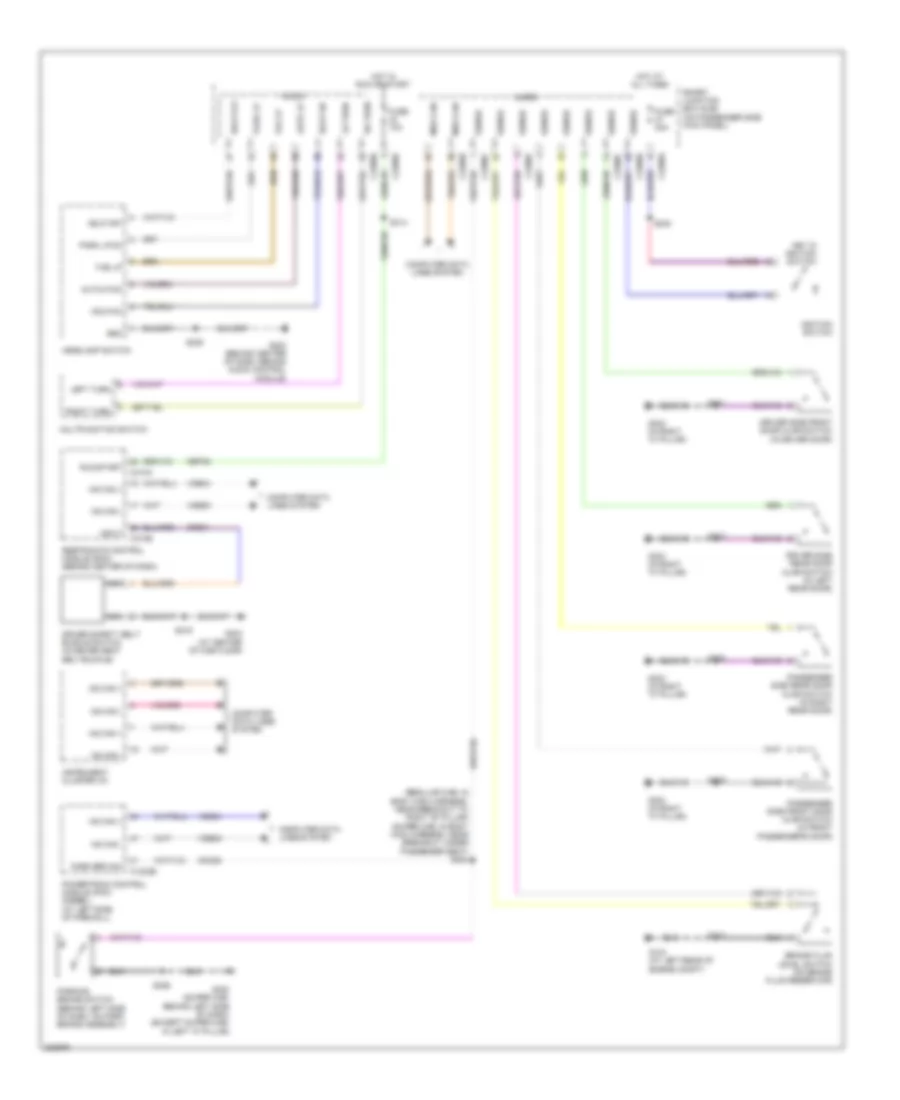 https://portal-diagnostov.com/license.html
Automotive Electricians Portal FZCO
Automotive Electricians Portal FZCO
https://portal-diagnostov.com/license.html
https://portal-diagnostov.com/license.html
Automotive Electricians Portal FZCO
Automotive Electricians Portal FZCOList of elements for Warning Systems Wiring Diagram for Ford Cab & Chassis F350 Super Duty 2008:
- (regular cab: in body main harness, near breakout to right "b" pillar) (super cab: in body main harness, near breakout under passenger seat) s304
- Auto lp
- Autolp on
- Brake fluid level switch (on brake fluid reservoir)
- C1232b
- C2280a
- C2280b
- C2280c
- C2280d
- C2280f
- C310a
- C310b
- Cbp32
- Cmc25
- Computer data lines system
- Cr201
- Driver safety belt buckle switch (in driver seat belt buckle)
- Driver side front door ajar switch (in driver door)
- Driver side rear door ajar switch (in left rear door)
- Fog lp
- Fuse 10a
- Fuse 20a
- G104 (at left rear of engine compt)
- G203 (behind center of dash, behind audio control module)
- G300 (super cab: behind left side of dash) (except super cab: in left "a" pillar)
- G302 (in right "a" pillar)
- G303 (at center of cab floor)
- Gnd
- Hdlp off
- Hdlp on
- Headlamp switch
- Hot at all times
- Hot in run or start
- Hs can +
- Hs can -
- Ignition switch
- Input
- Instrument cluster (ic)
- Key in ignition switch
- Left turn
- Lh turn
- Med can
- Micro
- Ms can +
- Ms can -
- Multifunction switch
- Nca
- Park brk sw
- Park lp
- Park lp on
- Parking brake switch (behind left side of dash, on park brake assembly)
- Passenger side front door ajar switch (in front passenger's door)
- Passenger side rear door ajar switch (in right rear door)
- Powertrain control module (pcm) (diesel) (at left side of firewall)
- Restraints control module (rcm) (behind center of dash)
- Rh turn
- Right turn
- Run/start
- S113
- S235
- S240
- S308
- S314
- S316
- S323
- S326
- S501
- S639
- Sense
- Smart junction box (sjb) (on passenger side kick panel)
- Vdb04
- Vdb05
WIPER/WASHER
Wiper/Washer Wiring Diagram for Ford Cab & Chassis F350 Super Duty 2008
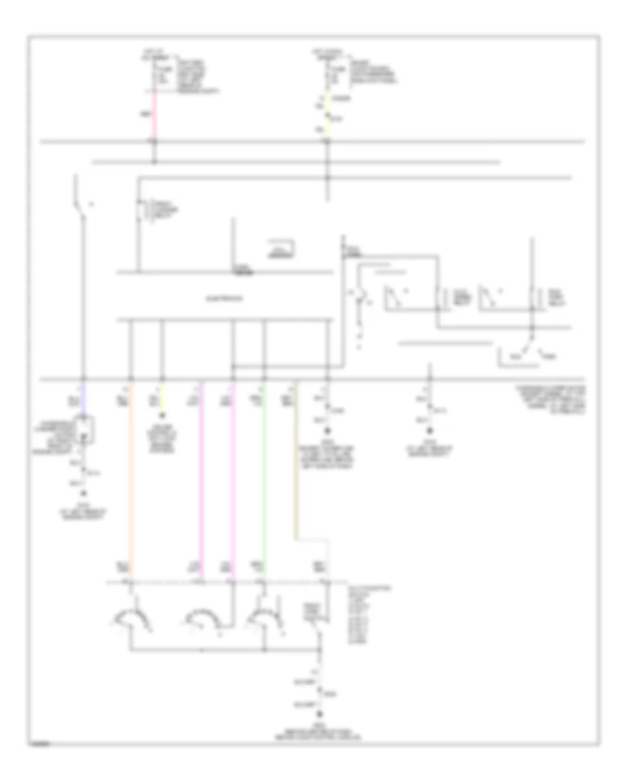 https://portal-diagnostov.com/license.html
Automotive Electricians Portal FZCO
Automotive Electricians Portal FZCO
https://portal-diagnostov.com/license.html
https://portal-diagnostov.com/license.html
Automotive Electricians Portal FZCO
Automotive Electricians Portal FZCOList of elements for Wiper/Washer Wiring Diagram for Ford Cab & Chassis F350 Super Duty 2008:
- 4) int 2 5) int 3 6) int 4 7) low 8) high
- Battery junction box (bjb) (at left rear of engine compt)
- C2280e
- Cruise control & anti-lock brakes systems
- Electronics
- Front wash switch
- Front washer relay
- Fuse 30a
- Fuse 5a
- G104 (at left rear of engine compt)
- G203 (behind center of dash, behind audio control module)
- G300 (except super cab: in left "a" pillar) (super cab: behind left side of dash)
- Hall sensor
- Hi/lo speed relay
- Hot at all times
- Hot in run or acc
- Multi-function switch 1) off 2) auto 3) int 1
- Park
- Park sense
- Red
- Run
- Run/ park
- Run/ park relay
- S104
- S113
- S185
- S235
- Smart junction box (on passenger side kick panel)
- Windshield washer pump motor (at right front of engine compt)
- Windshield wiper motor (except diesel: at top left side of firewall) (diesel: at left side of firewall)

 Čeština
 Dansk
Dansk Deutsch
 Ελληνικά
 English
 English
 Español
 Suomi
Suomi Français
 Français
 עברית
עברית Hrvatski
 Magyar
 Italiano
 日本語
日本語 한국어
한국어 Nederlands
 Polski
 Português
 Português
 Română
 Русский
 Slovenčina
 Slovenščina
 Svenska
 中文 (中国)
