AIR CONDITIONING
Heater Wiring Diagram for Ford Ranger 2006
 https://portal-diagnostov.com/license.html
Automotive Electricians Portal FZCO
Automotive Electricians Portal FZCO
https://portal-diagnostov.com/license.html
https://portal-diagnostov.com/license.html
Automotive Electricians Portal FZCO
Automotive Electricians Portal FZCO
List of elements for Heater Wiring Diagram for Ford Ranger 2006:
- (at left front of vehicle floor) g205
- (at left side of engine compt) g103
- (at right fender) s123
- (at right rear of engine compartment) g105
- (in main harness, behind center of dash)
- (in main harness, behind center of dash) s203
- (left side of engine compt) s108
- Battery junction box (bjb) (at left rear side of engine compartment)
- Blend door actuator (behind right side of dash)
- Blower motor relay
- Blower motor switch
- C2280b
- C294a
- C294b
- C294c
- C294d
- Defrost
- Floor
- Front function selector switch assembly
- Front heater blower motor resistor (right rear of engine compt, near blower motor)
- Fuse 10a
- Fuse 30a
- G205 (at left front of vehicle floor)
- Heater blower motor (right rear of engine compartment, on firewall)
- High
- Hot at all times
- Hot in run
- Illumination
- Interior lights system
- Low
- Max
- Medium high
- Medium low
- Microprocessor
- Mix
- Mode switch
- Normal
- Off
- Powertrain control module (pcm) (right rear of engine compt)
- S108 (left side of engine compt)
- S206 (in main harness, near breakout for audio unit)
- S216
- Smart junction box (sjb) (behind right side of dash)
- Temperature control potentiometer
- Vent
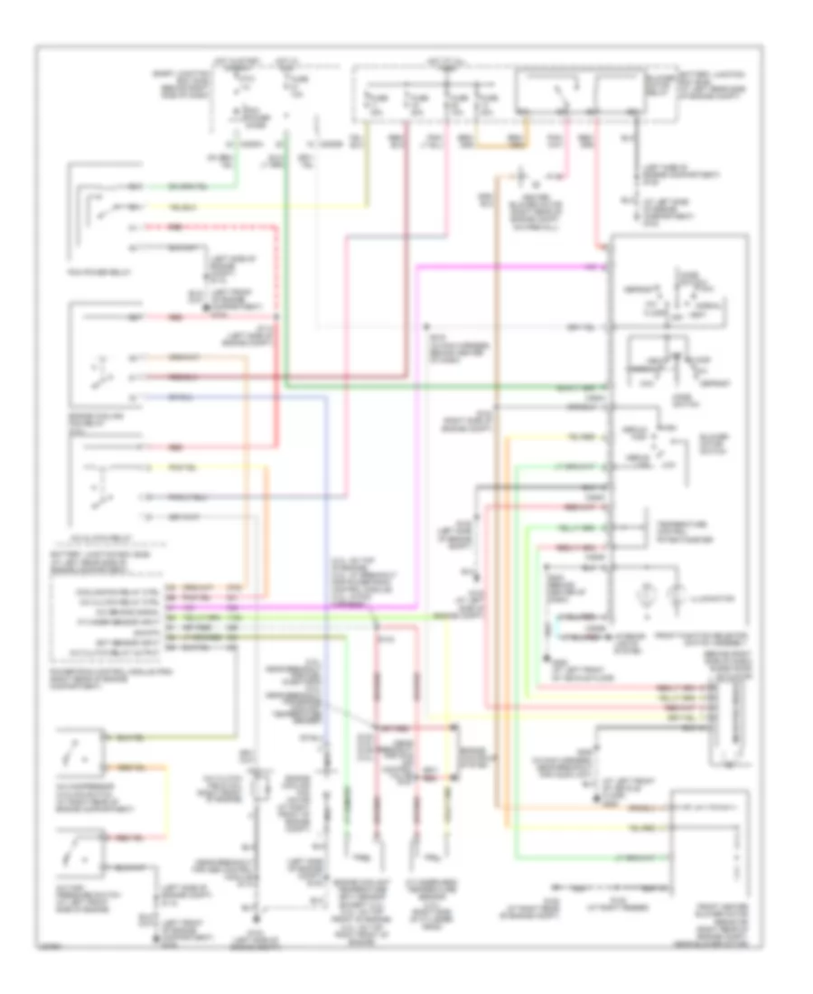
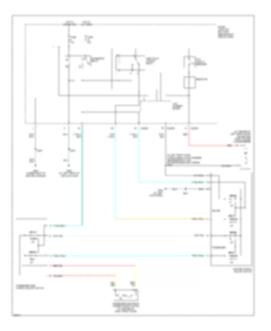
Manual A/C Wiring Diagram for Ford Ranger 2006
 https://portal-diagnostov.com/license.html
Automotive Electricians Portal FZCO
Automotive Electricians Portal FZCO
https://portal-diagnostov.com/license.html
https://portal-diagnostov.com/license.html
Automotive Electricians Portal FZCO
Automotive Electricians Portal FZCOList of elements for Manual A/C Wiring Diagram for Ford Ranger 2006:
- (2.3l: on top of engine) (3.0l: at breakout for powertrain control module) (4.0l: in pcm harness)
- (3.0l: near breakout for fuel injector 6) (4.0l: near breakout for engine coolant temperature sender)
- (at left front of vehicle floor)
- (at left side of engine compartment) g103
- (behind right side of dash) blend door actuator
- (in main harness, behind center of dash)
- (left front of engine compartment) g104
- (left side of engine compartment) s108
- (left side of engine compt) s108
- (left side of engine compt) s118
- (near breakout for abs control module) s110
- (near breakout for idle air control valve) s151
- A/c clutch field coil (right front of engine)
- A/c clutch relay
- A/c clutch relay ctrl
- A/c clutch relay output
- A/c compressor cycling switch (at right rear of engine compartment)
- A/c demand signal
- A/c high pressure switch (at left front side of engine)
- Battery junction box (bjb) (at left rear side of engine compartment)
- Battery junction box (bjb) (at left rear side of engine compt)
- Blower motor relay
- Blower motor switch
- C2280a
- C2280b
- C294a
- C294b
- C294c
- C294d
- Cooling fan relay ctrl
- Cylinder sensor input
- Cylinder-head temperature sensor (2.3l) (right side of cylinder head)
- Defrost
- Ect sensor input
- Engine controls system
- Engine coolant temperature (ect) sensor (except 2.3l) (3.0l: on top front of engine) (4.0l: on top right front of engine)
- Engine cooling fan motor (at right front of engine compt)
- Engine cooling fan relay (2.3l)
- Floor
- Front function selector switch assembly
- Front heater blower motor resistor (right rear of engine compt, near blower motor)
- Fuse 10a
- Fuse 20a
- Fuse 30a
- G103 (at left side of engine compt)
- G103 (left side of engine compt)
- G105 (at right rear of engine compt)
- G205
- G205 (at left front of vehicle floor)
- Heater blower motor (right rear of engine compt, on firewall)
- High
- Hot at all times
- Hot in run
- Hot in start or run
- Illumination
- Interior lights system
- Low
- Max
- Medium high
- Medium low
- Microprocessor
- Mix
- Mode switch
- Nca
- Normal
- Of engine compartment) g104
- Off
- Pcm power diode
- Pcm power relay
- Powertrain control module (pcm) (right rear of engine compartment)
- Ptc 1a
- Red
- S108 (left side of engine compt)
- S113 (left side of engine compt)
- S123 (at right fender)
- S124 (right side of engine compt)
- S133 (4.0l) s139 (3.0l)
- S143
- S203 (behind center of dash)
- S206 (in main harness, near breakout for audio unit)
- S216
- Sig rtn
- Smart junction box (sjb) (behind right side of dash)
- Temperature control potentiometer
- Vent
ANTI-LOCK BRAKES
Anti-lock Brakes Wiring Diagram for Ford Ranger 2006
 https://portal-diagnostov.com/license.html
Automotive Electricians Portal FZCO
Automotive Electricians Portal FZCO
https://portal-diagnostov.com/license.html
https://portal-diagnostov.com/license.html
Automotive Electricians Portal FZCO
Automotive Electricians Portal FZCOList of elements for Anti-lock Brakes Wiring Diagram for Ford Ranger 2006:
- (at left front of vehicle floor) g205
- (at right front wheel) right front wheel speed sensor
- 4wd
- 4x4 sta
- Abs control module (on left front of engine compt)
- Abs ind
- Abs pump motor (at left front of engine compt)
- Battery junction box (bjb) (at left rear side of engine compt)
- Brake fluid level switch (at left rear of engine compt, on brake fluid reservoir)
- Brake pedal position switch (behind left side of dash, on brake pedal support)
- C220b
- C2280b
- Computer data lines system
- Fluid level status
- Fuse 10a
- Fuse 17 40a
- Fuse 33 30a
- Fuse 5a
- G102 (at left side of engine compt)
- G103 (at left side of engine compt)
- Ground
- Hot at all times
- Hot in run
- Instrument cluster
- Iso
- Left front wheel speed sensor (at left front wheel)
- Low brake fluid level/ park brake ind
- Nca
- Pwr
- Rear axle speed sensor (top of rear differential)
- Red
- Red red
- Red/pnk
- S110
- S117 (in dash to headlight junction harness, near breakout for abs control module)
- S221
- Smart junction box (sjb) (behind right side of dash)
- Vbatt
- Vpwr
- Vref
ANTI-THEFT
Forced Entry Wiring Diagram for Ford Ranger 2006
 https://portal-diagnostov.com/license.html
Automotive Electricians Portal FZCO
Automotive Electricians Portal FZCO
https://portal-diagnostov.com/license.html
https://portal-diagnostov.com/license.html
Automotive Electricians Portal FZCO
Automotive Electricians Portal FZCOList of elements for Forced Entry Wiring Diagram for Ford Ranger 2006:
- (at left front of vehicle floor)
- C2280a
- C2280b
- C2280c
- C2280d
- Data link connector (dlc) (at bottom of steering column)
- Door lock/
- Driver door unlock relay
- Driver side door lock switch
- Driver side rear door ajar switch (4 door) (at bottom rear of left rear door)
- Exterior lights system
- Fuse 10a
- Fuse 15a
- Fuse 20a
- Fuse 5a
- G200 (at left kick panel)
- G204 (under front of center console)
- G205
- G205 (at left front of vehicle floor)
- Horn relay
- Horns system
- Hot at all times
- Instrument cluster system
- Interior lights system
- Left front door ajar switch (w/o power equipment: (at rear of left front door)
- Left front door lock actuator (w/ power equipment: at rear of left front door)
- Lock
- Low current board
- Main light switch
- Park lamp relay
- Passenger side door lock switch
- Passenger side rear door ajar switch (4 door) (at bottom rear right rear door)
- Red
- Right front door ajar switch (w/o power equipment: (at rear of right front door)
- Right front door lock actuator (w/ power equipment: at rear of right front door)
- S203
- S209
- S234 (near right kick panel)
- S409
- S410 (w/ 4 door) (in interior light harness, near breakout for c710)
- S501
- S600
- S600 (w/ power equipment)
- Smart junction box (sjb) (behind right side of dash)
- Unlock
- Unlock relay
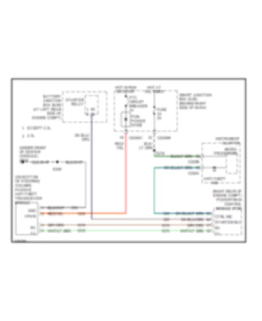
Passive Anti-theft Wiring Diagram for Ford Ranger 2006
 https://portal-diagnostov.com/license.html
Automotive Electricians Portal FZCO
Automotive Electricians Portal FZCO
https://portal-diagnostov.com/license.html
https://portal-diagnostov.com/license.html
Automotive Electricians Portal FZCO
Automotive Electricians Portal FZCOList of elements for Passive Anti-theft Wiring Diagram for Ford Ranger 2006:
- (on bottom of steering column) passive anti-theft transceiver module
- (right rear of engine compt) powertrain control module (pcm)
- (under front of center console) g204
- 2.3l
- Anti-theft ind
- Battery junction box (bjb) (at left rear side of engine compt)
- C220a
- C220b
- C2280b
- C2280c
- Ctrl ind
- Except 2.3l
- Fuse 5a
- Gnd
- Hot at all times
- Hot in run or start
- Instrument cluster
- Micro- processor
- Pcm power diode
- Ptc circuit breaker 1a
- S209
- S218
- Smart junction box (sjb) (behind right side of dash)
- Starter relay
- Starter rly
- Vpwr
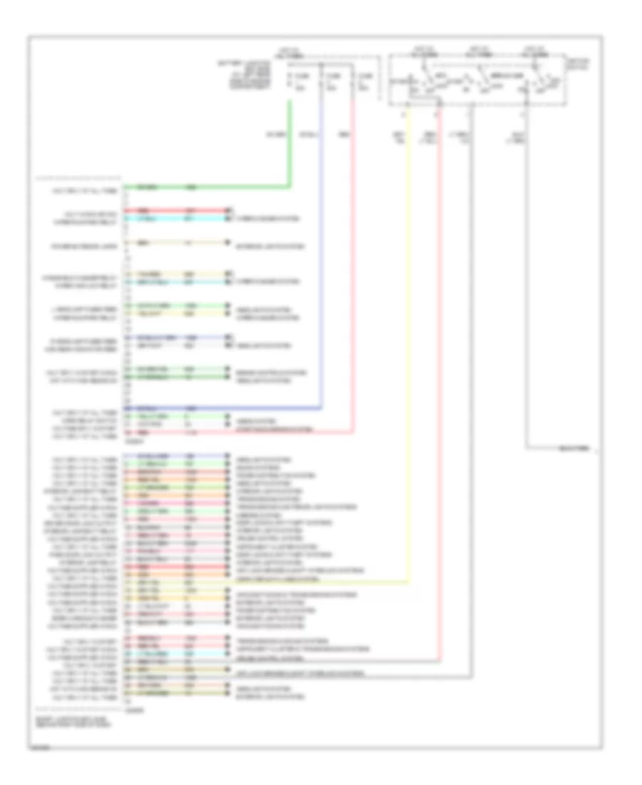
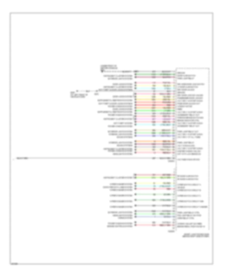
BODY CONTROL MODULES
Body Control Modules Wiring Diagram (1 of 2) for Ford Ranger 2006
 https://portal-diagnostov.com/license.html
Automotive Electricians Portal FZCO
Automotive Electricians Portal FZCO
https://portal-diagnostov.com/license.html
https://portal-diagnostov.com/license.html
Automotive Electricians Portal FZCO
Automotive Electricians Portal FZCOList of elements for Body Control Modules Wiring Diagram (1 of 2) for Ford Ranger 2006:
- Acc
- Air conditioning & transmissions systems
- Air conditioning system
- Anti-lock brakes & shift interlock systems
- Battery junction box (bjb) (at left rear side of engine compartment)
- C2280a
- C2280b
- Computer data lines system
- Cruise control system
- Door locks & anti-theft systems
- Driver door lock output
- Emer warning flasher
- Engine controls system
- Exterior lights system
- Fuse 40a
- Fuse 50a
- Headlights system
- High beam indicator feed
- Horn relay switch
- Horns system
- Hot at all times
- Hot with high beams on
- Ignition switch
- Instrument cluster & transmissions systems
- Instrument cluster system
- Interior lamp relay
- Interior lamp/batt relay
- Interior lights system
- L headlamp fused feed
- Lock
- Mirrors system
- Off
- On off
- Pass door lock output
- Power distribution system
- Power exterior lamps
- R headlamp fused feed
- Red
- Smart junction box (sjb) (behind right side of dash)
- Sound systems
- Start
- Starting/charging system
- Tan/red
- Transmissions & exterior lights systems
- Transmissions & sound systems
- Transmissions system
- Volt in run or acc
- Volt sply at all times
- Volt sply in start
- Volt sply in start & run
- Voltage sply in start
- Windshield washer relay
- Wiper high/low relay
- Wiper run/park relay
- Wiper/washer system
Body Control Modules Wiring Diagram (2 of 2) for Ford Ranger 2006
 https://portal-diagnostov.com/license.html
Automotive Electricians Portal FZCO
Automotive Electricians Portal FZCO
https://portal-diagnostov.com/license.html
https://portal-diagnostov.com/license.html
Automotive Electricians Portal FZCO
Automotive Electricians Portal FZCOList of elements for Body Control Modules Wiring Diagram (2 of 2) for Ford Ranger 2006:
- (under front of center console) g204
- Accessory relay out
- Anti-theft & door locks systems
- Anti-theft system
- Brake indicator ctrl
- Brake pedal position sw in
- C2280c
- C2280d
- Computer data lines system
- Door ajar switch
- Door locks system
- Drv door lock sw unlock
- Drv door unlock
- Drv side door lock switch
- Engine controls system
- Exterior lights system
- Feed
- Fog lamp relay sw pwr
- G205 (at left front of vehicle floor)
- Ground
- Headlights system
- Horn relay ctrl
- Horns system
- Hot with low beams on
- Instrument cluster system
- Instrument cluster system power windows system
- Interior lights system
- Iso bus
- Lf door ajar switch
- Master window adj sw
- Park lamp relay
- Park lamp relay ctrl
- Park lamp relay out
- Parking brake switch sig
- Pass door unlock out
- Passenger door lock sw
- Power windows system
- Red
- Rf door ajar switch
- S203
- S209
- Smart junction box (sjb) (behind right side of dash)
- Sound systems
- Volt in run & acc
- Volt sply at all times
- Volt sply in start & run
- Voltage in run or acc
- Window adjust sw feed
- Window motor
- Wiper switch circuit a
- Wiper switch circuit b
- Wiper switch circuit c
- Wiper switch circuit high
- Wiper switch circuit washer
- Wiper/washer system
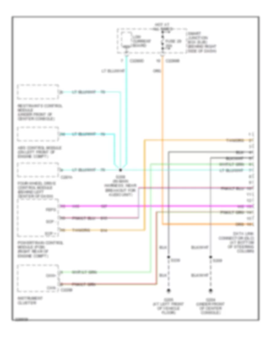
COMPUTER DATA LINES
Computer Data Lines Wiring Diagram for Ford Ranger 2006
 https://portal-diagnostov.com/license.html
Automotive Electricians Portal FZCO
Automotive Electricians Portal FZCO
https://portal-diagnostov.com/license.html
https://portal-diagnostov.com/license.html
Automotive Electricians Portal FZCO
Automotive Electricians Portal FZCOList of elements for Computer Data Lines Wiring Diagram for Ford Ranger 2006:
- Abs control module (on left front of engine compt)
- C220b
- C2280b
- C2280d
- C281a
- Can+
- Can-
- Data link connector (dlc) (at bottom of steering column)
- Feps
- Four-wheel drive control module (behind left center of dash)
- Fuse 29 20a
- G204 (under front of center console)
- G205 (at left front of vehicle floor)
- Hot at all times
- Instrument cluster
- Iso
- Low current board
- Powertrain control module (pcm) (right rear of engine compt)
- Restraints control module (under front of center console)
- S208 (in main harness, near breakout for audio unit)
- S209
- S236
- Scp +
- Scp -
- Smart junction box (sjb) (behind right side of dash)
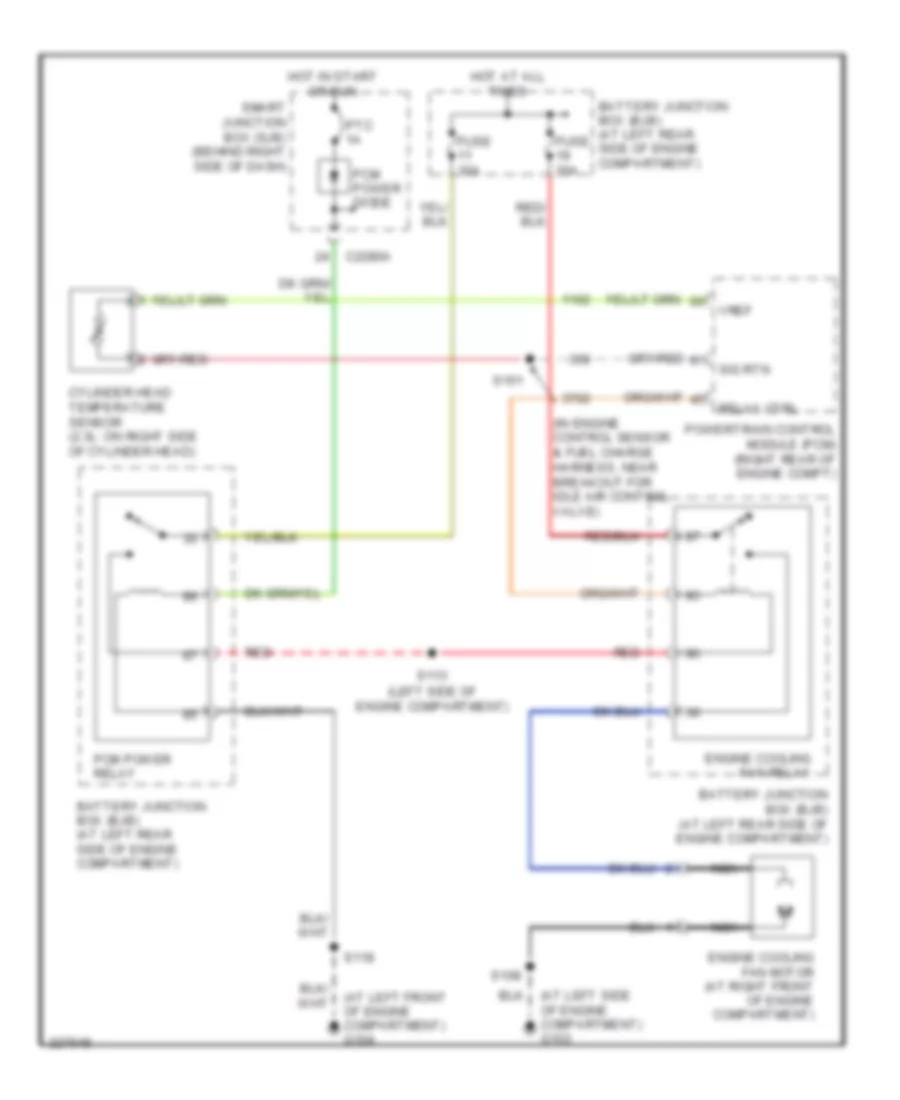
COOLING FAN
2.3L
2.3L, Cooling Fan Wiring Diagram for Ford Ranger 2006
 https://portal-diagnostov.com/license.html
Automotive Electricians Portal FZCO
Automotive Electricians Portal FZCO
https://portal-diagnostov.com/license.html
https://portal-diagnostov.com/license.html
Automotive Electricians Portal FZCO
Automotive Electricians Portal FZCOList of elements for 2.3L, Cooling Fan Wiring Diagram for Ford Ranger 2006:
- (at left front of engine compartment) g104
- (at left side of engine compartment) g103
- (in engine control sensor & fuel charge harness, near breakout for idle air control valve)
- (left side of engine compartment)
- Battery junction box (bjb) (at left rear side of engine compartment)
- C2280a
- Cylinder head temperature sensor (2.3l: on right side of cylinder head)
- Engine cooling fan motor (at right front of engine compartment)
- Engine cooling fan relay
- Fuse 20a
- Fuse 30a
- Hot at all times
- Hot in start or run
- Nca
- Pcm power diode
- Pcm power relay
- Powertrain control module (pcm) (right rear of engine compt)
- Ptc 1a
- Red
- Relay ctrl
- S108
- S113
- S118
- S151
- Sig rtn
- Smart junction box (sjb) (behind right side of dash)
- Vref
CRUISE CONTROL
Cruise Control Wiring Diagram for Ford Ranger 2006
 https://portal-diagnostov.com/license.html
Automotive Electricians Portal FZCO
Automotive Electricians Portal FZCO
https://portal-diagnostov.com/license.html
https://portal-diagnostov.com/license.html
Automotive Electricians Portal FZCO
Automotive Electricians Portal FZCOList of elements for Cruise Control Wiring Diagram for Ford Ranger 2006:
- 10a
- A/t
- Air bag sliding contact (at bottom of steering column)
- Brake pedal position switch (behind left side of dash, on brake pedal support)
- C218a
- C220a
- C2280b
- C2280c
- Clutch pedal position switch (behind left side of dash, top of brake pedal support)
- Coast(-)
- Cruise ctrl ind
- Deactivator switch (at left rear of engine compt)
- Fuse 20
- Fuse 26
- Fuse 32
- Fuse 7
- G105 (at right rear of engine compartment)
- G204 (under front of center console)
- G205 (at left front of vehicle floor)
- Gnd
- Ground steering wheel assembly
- Harness, at left side of dash)
- Head
- Horns system
- Hot at all times
- Hot in run
- Hot in start or run
- Illumination
- In put
- Instrument cluster
- Interior lights system
- M/t
- Main light switch
- Micro- processor
- Off
- Park
- Powertrain control module (pcm) (right rear of engine compartment)
- Rest
- Resume
- S116 (left side of engine compartment)
- S123
- S209
- S236
- Set(+)
- Sig rtn
- Smart junction box (sjb) (behind right side of dash)
- Speed control servo (in right rear of engine compartment)
- Speed control indicator
- Speed control on/off switch
- Speed control set/ resume switch
- Vpwr
- Vref
- Vss
ENGINE PERFORMANCE
2.3L
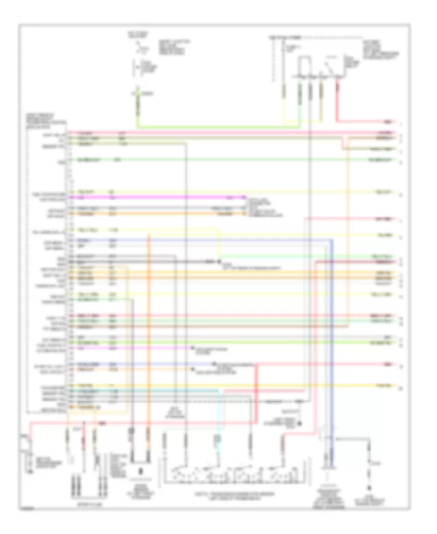
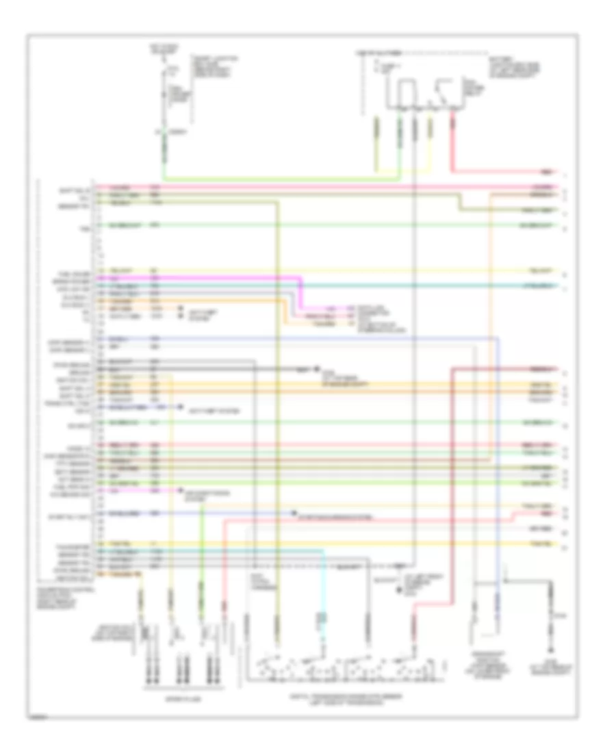
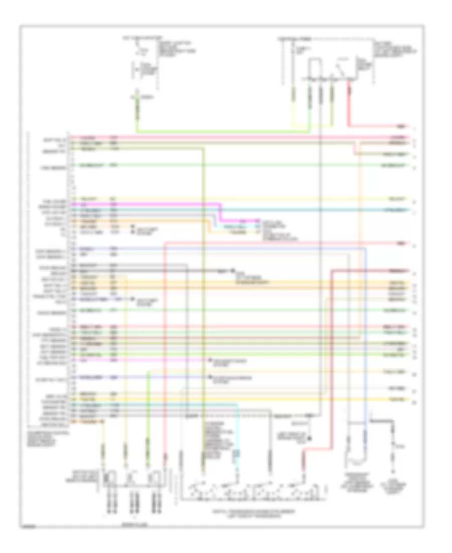
2.3L, Engine Performance Wiring Diagram (1 of 4) for Ford Ranger 2006
 https://portal-diagnostov.com/license.html
Automotive Electricians Portal FZCO
Automotive Electricians Portal FZCO
https://portal-diagnostov.com/license.html
https://portal-diagnostov.com/license.html
Automotive Electricians Portal FZCO
Automotive Electricians Portal FZCOList of elements for 2.3L, Engine Performance Wiring Diagram (1 of 4) for Ford Ranger 2006:
- (at bottom of steering column)
- (left front of engine compt)
- (right rear of engine compt) powertrain control module (pcm)
- A/c demand sig
- Act sens in
- Air conditioning system
- Battery junction box (bjb) (at left rear side of engine compt)
- Ccs
- Ckp sens +
- Ckp sens -
- Cool fan rly
- Cooling fans system
- Crankshaft position (ckp) sensor (on lower right front of engine)
- Data link connector (dlc)
- Digital transmission range (dtr) sensor (left side of transmission)
- Fail safe cool in
- Fuel pump rly
- Fuel pump/gauge
- Fuse 11 30a
- G104
- G106 (at top rear of engine compt)
- Gnd
- Ho2s 11 in
- Hot at all times
- Hot in run or start
- Ignition coil
- Ignition coil (on top right side of engine)
- Ignition transformer capacitor
- Knock sens
- Knock sensor (at left front of engine)
- Maf sig
- Mil
- Mod prog sig
- Nca
- Pcm power diode
- Pcm power relay
- Psp sw
- Ptc 1a
- Red
- S107 (on top of engine)
- S118
- S145
- S147
- Scp bus+
- Scp bus-
- Sensor tr1
- Sensor tr2
- Sensor tr4
- Shift sol a
- Shift sol b
- Smart junction box (sjb) (behind right side of dash)
- Spark plugs
- Start rly cntl
- Starting/charging system
- Tachometer
- Tft sens in
- Trans cntl sw
- Tss
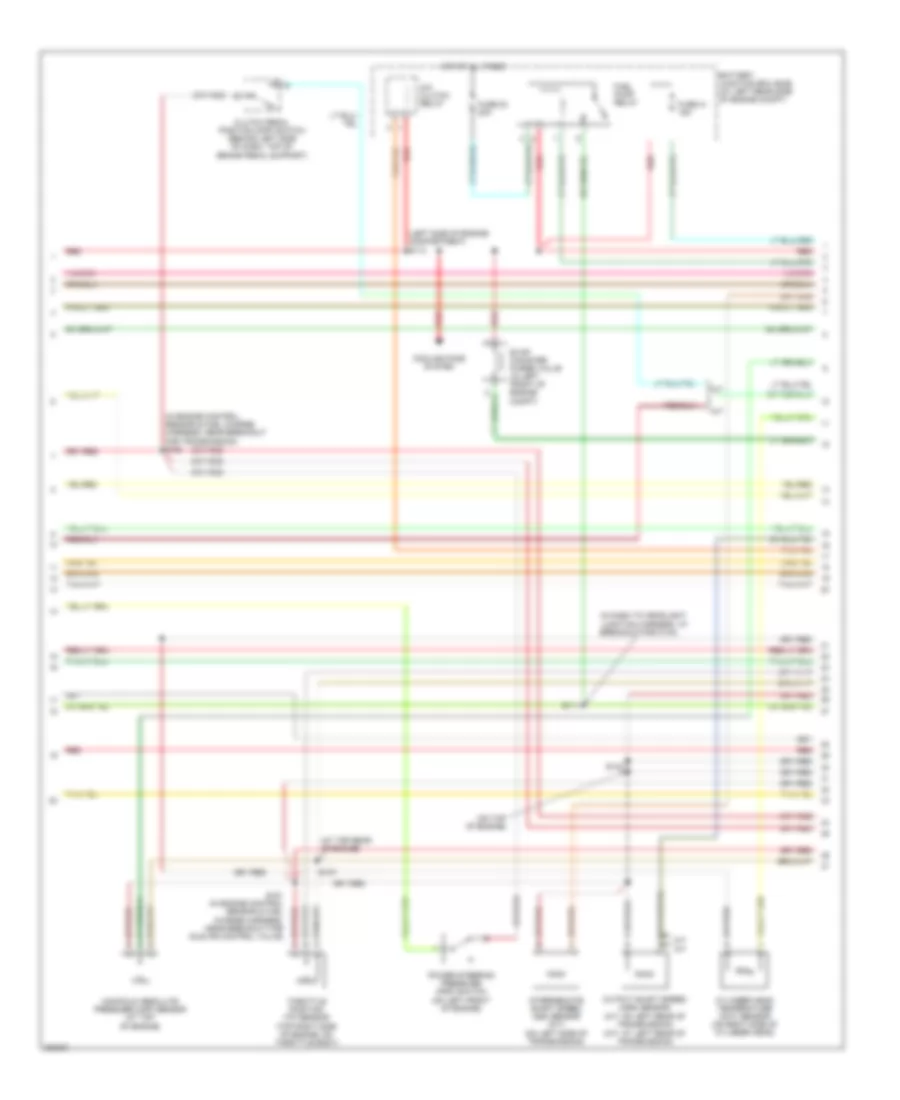
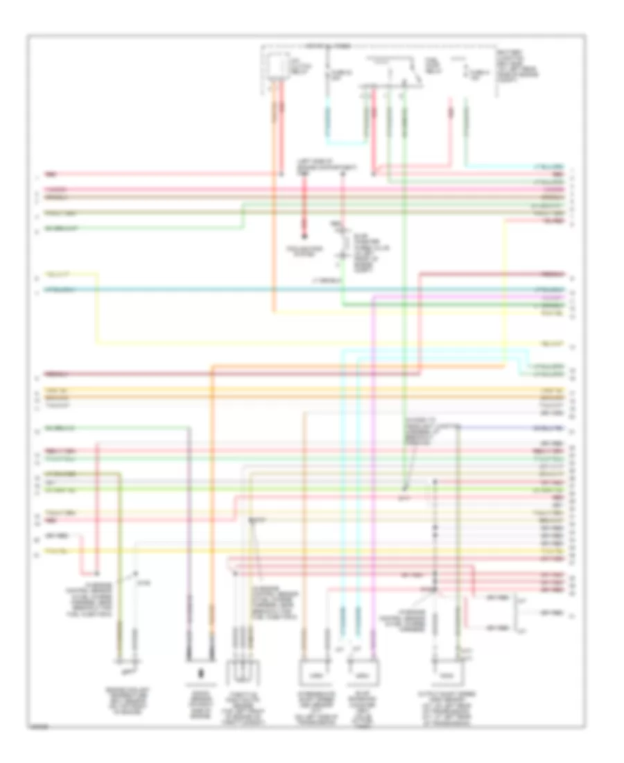
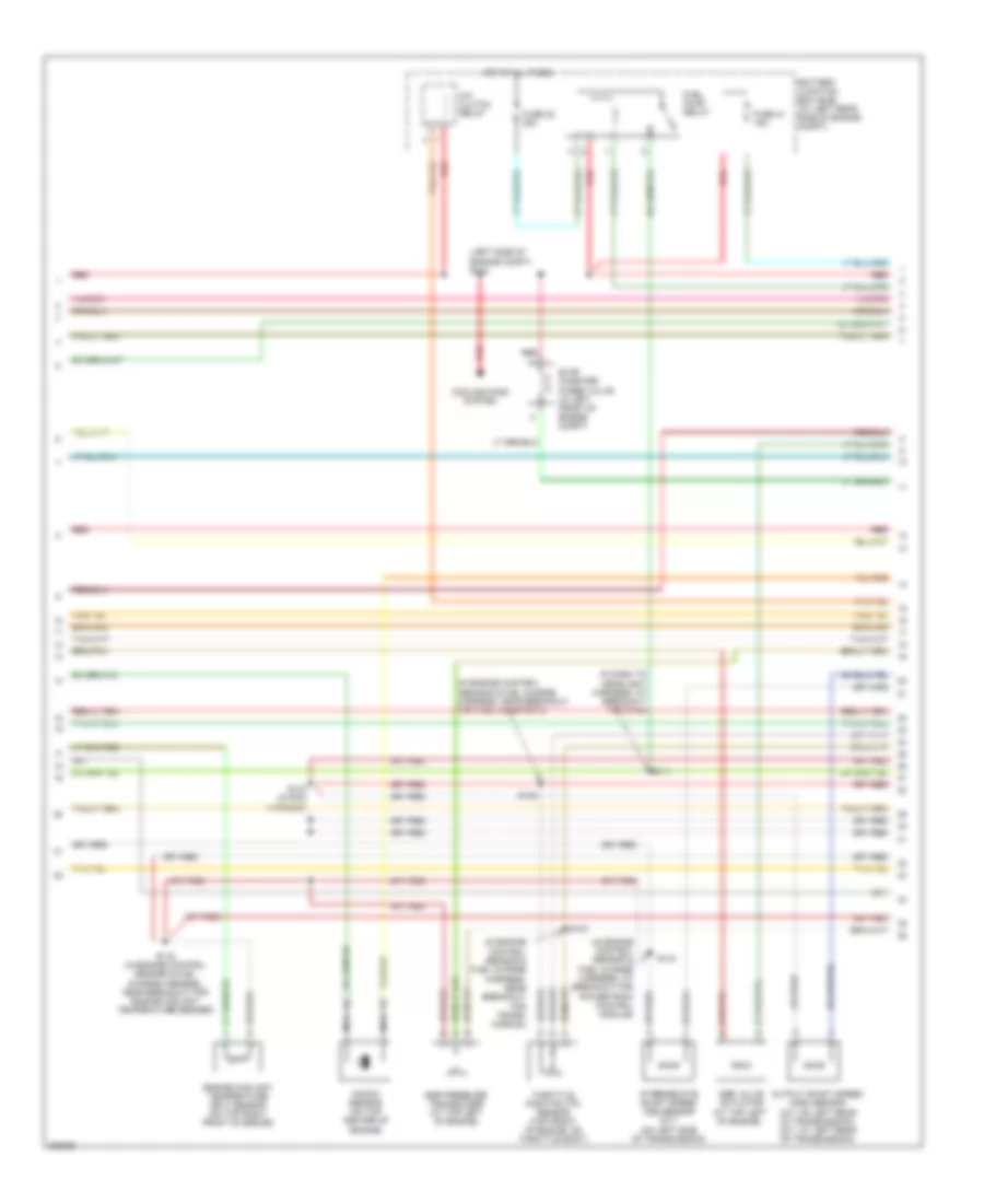
2.3L, Engine Performance Wiring Diagram (2 of 4) for Ford Ranger 2006
 https://portal-diagnostov.com/license.html
Automotive Electricians Portal FZCO
Automotive Electricians Portal FZCO
https://portal-diagnostov.com/license.html
https://portal-diagnostov.com/license.html
Automotive Electricians Portal FZCO
Automotive Electricians Portal FZCOList of elements for 2.3L, Engine Performance Wiring Diagram (2 of 4) for Ford Ranger 2006:
- (at top rear of engine)
- (in dash to headlight junction harness, at breakout for c144)
- (in engine control sensor & fuel charge harness, near breakout for transmission) s152
- (left side of engine compartment) s113
- (m/t: at left rear of transmission)
- (on top of engine)
- A/c clutch relay
- A/t
- Battery junction box (bjb) (at left rear side of engine compt)
- Clutch pedal position (cpp) switch (behind left side of dash, top of brake pedal support)
- Cooling fans system
- Cylinder head temperature (cht) sensor (on right side of cylinder head)
- Evap canister purge valve (in left front of engine compt)
- Fuel pump relay
- Fuse 23 20a
- Fuse 41 15a
- Hot at all times
- Intermediate shaft speed (iss) sensor (a/t) (on left side of transmission)
- M/t
- Manifold absolute pressure (map) sensor (at top of engine)
- Output shaft speed (oss) sensor (a/t: on left rear of transmission)
- Power steering pressure (psp) switch (on left front of engine)
- Red
- S111
- S137
- S143
- S151 (in engine control sensor & fuel charge harness, near breakout for idle air control valve)
- Throttle position (tp) sensor (top right side of engine, on throttle body)
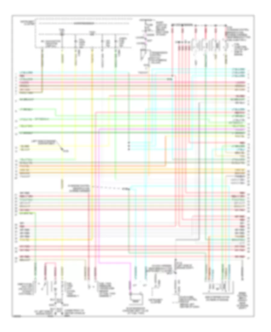
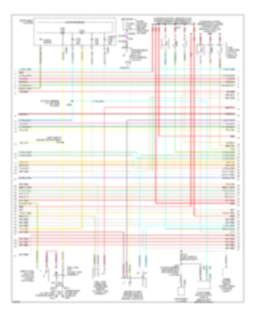
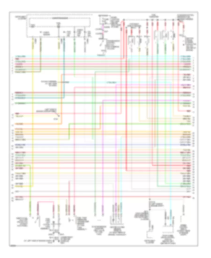
2.3L, Engine Performance Wiring Diagram (3 of 4) for Ford Ranger 2006
 https://portal-diagnostov.com/license.html
Automotive Electricians Portal FZCO
Automotive Electricians Portal FZCO
https://portal-diagnostov.com/license.html
https://portal-diagnostov.com/license.html
Automotive Electricians Portal FZCO
Automotive Electricians Portal FZCOList of elements for 2.3L, Engine Performance Wiring Diagram (3 of 4) for Ford Ranger 2006:
- (at left side of engine compt) g103
- (in engine control sensor & fuel charge harness)
- (in main harness, near breakout for instrument cluster) s213
- (left side of engine compartment)
- (on top of engine)
- (under front of center console) g204
- A/t
- C220a
- C220b
- C281b
- Check fuel cap ind
- Egr stepper motor (on rear of engine)
- Evap emissions canister vent valve (at fuel tank)
- Fail- safe cool ind
- Four-wheel drive control module (behind left center of dash)
- Fuel injectors (at top left side of engine)
- Fuel lev sig
- Fuel tank pressure transducer sensor (at fuel tank assembly)
- Fuel tank unit (in fuel tank assembly)
- Fuse 10a
- Hot in run
- Inertia fuel shut-off (ifs) switch (in right kick panel)
- Instrument cluster
- M/t
- Malfunction indicator lamp (mil)
- Microprocessor
- Nca
- O/d off ind
- Red
- Red/pnk
- S116 (left side of engine compt)
- S125
- S148
- S149 (in engine control red sensor & fuel charge harness, near breakout for fuel injector 4)
- S150
- S153
- S215
- S237
- S405
- Smart junction box (sjb) (behind right side of dash)
- Speed control servo (in right rear of engine compt)
- Tach sig
- Tan
- Tan/red
- Transmission control switch (on steering column)
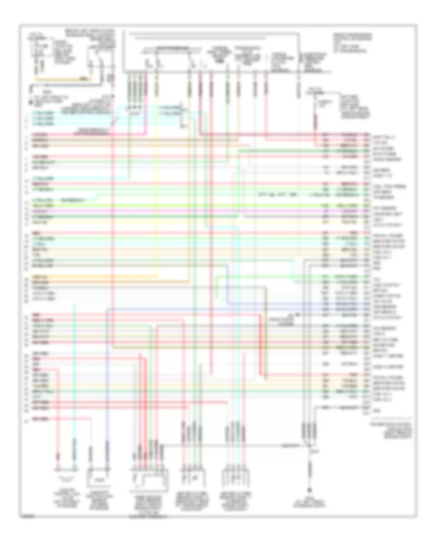
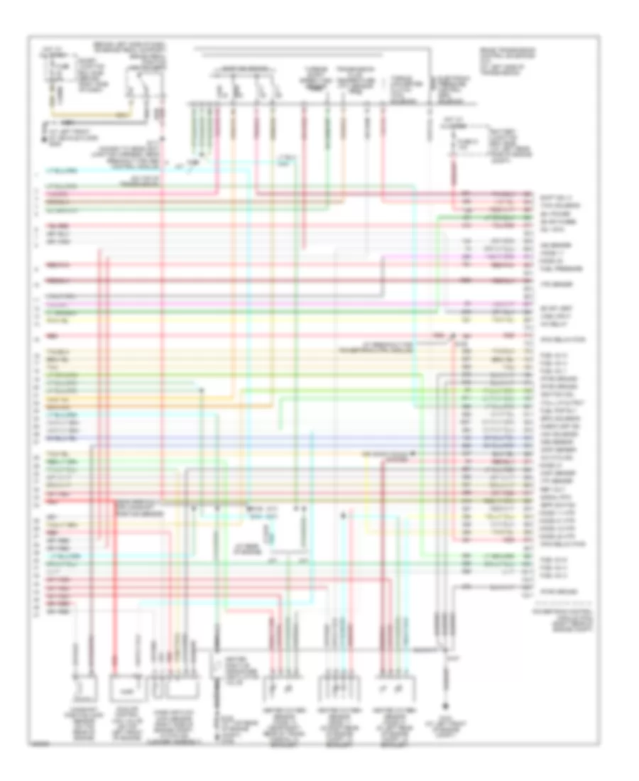
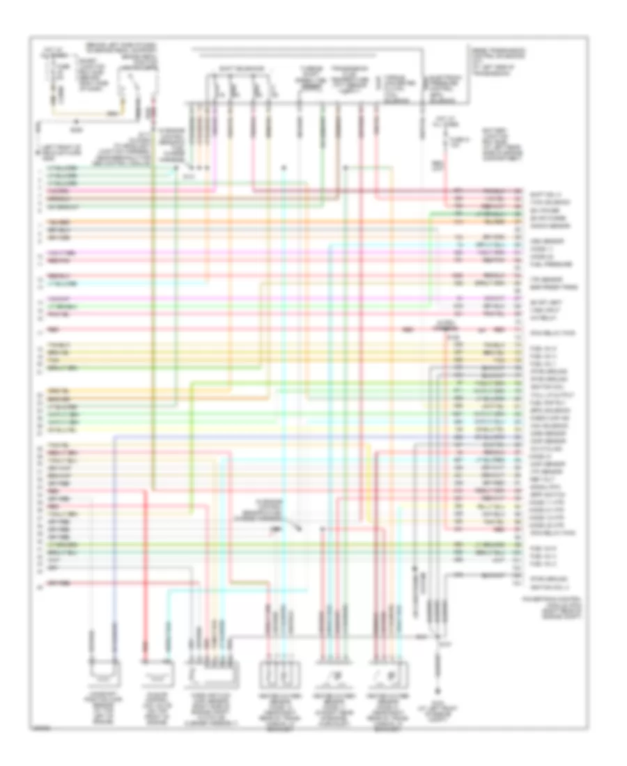
2.3L, Engine Performance Wiring Diagram (4 of 4) for Ford Ranger 2006
 https://portal-diagnostov.com/license.html
Automotive Electricians Portal FZCO
Automotive Electricians Portal FZCO
https://portal-diagnostov.com/license.html
https://portal-diagnostov.com/license.html
Automotive Electricians Portal FZCO
Automotive Electricians Portal FZCOList of elements for 2.3L, Engine Performance Wiring Diagram (4 of 4) for Ford Ranger 2006:
- (a/t)
- (at left front of vehicle floor) g205
- (b+) power
- (behind left side of dash, on brake pedal support) brake pedal position switch (bpp)
- (m/t)
- (near breakout for transmission)
- 5r44e transmission control solenoids (a/t) (at left side of transmission)
- A/c clutch rly
- Air conditioning system
- Battery junction box (bjb) (at left rear side of engine compartment)
- Bpp sw
- C2280b
- Camshaft position (cmp) sensor (on rear of engine)
- Canister vent
- Check cap ind
- Cht sensor
- Cmp sens in
- Egr step motor
- Electronic pressure control (epc) solenoid
- Epc sol
- Evap purge
- Fuel inj 1
- Fuel inj 2
- Fuel inj 3
- Fuel inj 4
- Fuel pump rly
- Fuel tank press
- Fuse 21 10a
- Fuse 5a
- G104 (at left front of engine compt)
- Gnd
- Heated oxygen sensor (ho2s) 11 (in rear of engine compt, in exhaust)
- Heated oxygen sensor (ho2s) 12 (near right rear of transmission, in exhaust)
- Ho2s 11 heater
- Ho2s 11 in
- Ho2s 12 heater
- Hot at all times
- Iac valve
- Idle air control (iac) valve (on top right of engine)
- Iss sens
- Knock sensor
- M/t
- Maf sensor
- Map sens
- Mass air flow (maf) sensor (right side of engine compt, within air cleaner assembly)
- Oss sensor
- Pcm rly power
- Powertrain control module (pcm) (right rear of engine compt)
- Red
- Red/pnk
- Ref voltage
- S107
- S117 (in dash to headlight junction harness, near breakout for abs control module)
- S154
- S236
- Shift sol c
- Shift solenoids
- Sig return
- Smart junction box (sjb) (behind right side of dash)
- Tan
- Tan/red
- Tcc sol
- Tcil
- Torque converter clutch (tcc) solenoid
- Tps in
- Tr sensor
- Transmission fluid temperature (tft) sensor
- Turbine shaft speed sensor (tss)
- Vss +
3.0L
3.0L, Engine Performance Wiring Diagram (1 of 4) for Ford Ranger 2006
 https://portal-diagnostov.com/license.html
Automotive Electricians Portal FZCO
Automotive Electricians Portal FZCO
https://portal-diagnostov.com/license.html
https://portal-diagnostov.com/license.html
Automotive Electricians Portal FZCO
Automotive Electricians Portal FZCOList of elements for 3.0L, Engine Performance Wiring Diagram (1 of 4) for Ford Ranger 2006:
- (at left front of engine compt) g104
- (ckp) sensor (+)
- (ckp) sensor (-)
- (dlc) (at bottom of steering column)
- (ect) sensor
- (ho2s) 12
- (maf) sensor rtn
- (mil)
- (pwr) ground
- (tft) sensor
- 4wd low ind
- A/c demand sig
- Act sens in
- Air conditioning system
- Anti-theft system
- Battery junction box (bjb) (at left rear side of engine compt)
- Connector
- Crankshaft position (ckp) sensor (on lower front of engine)
- Data link
- Digital transmission range (dtr) sensor (left side of transmission)
- Dlc bus (+)
- Dlc bus (-)
- Eprom power
- Fuel gauge
- Fuel pmp mon
- Fuse 11 30a
- G106 (at top rear of engine compt)
- Ground
- Hot at all times
- Hot in run or start
- Ignition coil
- Ignition coil (on top right side of engine)
- Ind in
- Ks input
- Nca
- Pcm power diode
- Pcm power relay
- Powertrain control module (pcm) (right rear of engine compt)
- Ptc 1a
- Red
- S107 (in pcm harness)
- S118
- S145
- Sensor tr1
- Sensor tr2
- Sensor tr4
- Shift sol a
- Shift sol b
- Shift sol d
- Smart junction box (sjb) (behind right side of dash)
- Spark plugs
- Start rly cntl
- Starting/charging system
- Tachometer
- Trans ctrl (tcs)
- Tss
3.0L, Engine Performance Wiring Diagram (2 of 4) for Ford Ranger 2006
 https://portal-diagnostov.com/license.html
Automotive Electricians Portal FZCO
Automotive Electricians Portal FZCO
https://portal-diagnostov.com/license.html
https://portal-diagnostov.com/license.html
Automotive Electricians Portal FZCO
Automotive Electricians Portal FZCOList of elements for 3.0L, Engine Performance Wiring Diagram (2 of 4) for Ford Ranger 2006:
- (a/t)
- (in dash to headlight junction harness, at breakout for c144)
- (in engine control sensor & fuel charge harness, near breakout for fuel injector 5)
- (in engine control sensor & fuel charge harness)
- (in engine control sensor & fuel charge harness, near breakout for fuel injector 6)
- (left side of engine compartment) s113
- (m/t)
- A/c clutch relay
- A/t
- Battery junction box (bjb) (at left rear side of engine compt)
- Cooling fans system
- Engine coolant temperature (ect) sensor (on top front of engine)
- Evap canister purge valve (in left front of engine compt)
- Evap emissions canister vent valve (at fuel tank)
- Fuel pump relay
- Fuse 23 20a
- Fuse 41 15a
- Hot at all times
- Intermediate shaft speed (iss) sensor (a/t) (on left side of transmission)
- Knock sensor (on right side of engine)
- M/t
- Nca
- Output shaft speed (oss) sensor (a/t: on left rear of transmission) (m/t: at left rear of transmission)
- Red
- S111
- S137
- S139
- S143
- Throttle position (tp) sensor (top left front of engine, on throttle body)
3.0L, Engine Performance Wiring Diagram (3 of 4) for Ford Ranger 2006
 https://portal-diagnostov.com/license.html
Automotive Electricians Portal FZCO
Automotive Electricians Portal FZCO
https://portal-diagnostov.com/license.html
https://portal-diagnostov.com/license.html
Automotive Electricians Portal FZCO
Automotive Electricians Portal FZCOList of elements for 3.0L, Engine Performance Wiring Diagram (3 of 4) for Ford Ranger 2006:
- (at left side of engine compt) g103
- (in engine control sensor & fuel charge harness, near breakout for fuel injector 3) s101
- (in engine control sensor & fuel charge harness, near breakout for heated oxygen sensor 21)
- (in main harness, at left side of dash)
- (left side of engine compartment) s125
- (under front of center console) g204
- 4wd low ind
- A/t
- C220a
- C220b
- C2280b
- C281b
- Check engine
- Check fuel cap ind
- Four wheel drive control module (behind left center of dash)
- Fuel injectors (at top right of engine)
- Fuel lev sig
- Fuel tank pressure transducer sensor (at fuel tank assembly)
- Fuel tank unit (in fuel tank assembly)
- Fuse 10a
- Heated oxygen sensor (ho2s) 22 (at right rear of engine, in exhaust)
- Hot in run
- Inertia fuel shut-off (ifs) switch (in right kick panel)
- Instrument cluster
- M/t
- Microprocessor
- Nca
- O/d off ind
- Red
- Red/pnk
- S104 red
- S116 (left side of engine compt)
- S213 (in main harness, near breakout for instrument cluster)
- S215
- S237
- S258
- S405
- Smart junction box (sjb) (behind right side of dash)
- Speed control servo (in right rear of engine compt)
- Tach sig
- Tan
- Transmission control switch (on steering column)
3.0L, Engine Performance Wiring Diagram (4 of 4) for Ford Ranger 2006
 https://portal-diagnostov.com/license.html
Automotive Electricians Portal FZCO
Automotive Electricians Portal FZCO
https://portal-diagnostov.com/license.html
https://portal-diagnostov.com/license.html
Automotive Electricians Portal FZCO
Automotive Electricians Portal FZCOList of elements for 3.0L, Engine Performance Wiring Diagram (4 of 4) for Ford Ranger 2006:
- (a/t)
- (at breakout for powertrain ctrl module)
- (at left front of vehicle floor) g205
- (at rear of engine)
- (b+) power
- (behind left side of dash, on brake pedal support) brake pedal position switch (bpp)
- (bpp) switch
- (cmp) sensor
- (epc) solenoid
- (evap) purge
- (evap) vent
- (ho2s) 11
- (ho2s) 11 htr
- (ho2s) 12 htr
- (ho2s) 21
- (ho2s) 21 htr
- (ho2s) 22
- (ho2s) 22 htr
- (iac) solenoid
- (m/t)
- (maf) sensor
- (near breakout for camshaft position sensor)
- (on top of transmission)
- (pcm relay) pwr
- (pwr) ground
- (tcc) solenoid
- (tcil) lp output
- (tp) sensor
- (tr) sensor
- (vss) input
- 5r44e transmission control solenoids (a/t) (at left side of transmission)
- A/c cycling
- A/c relay
- A/t
- Air conditioning system
- Battery junction box (bjb) (at left rear side of engine compt)
- C2280b
- Camshaft position (cmp) sensor (on top rear of engine)
- Check cap ind
- Electronic pressure control (epc) solenoid
- Fuel inj 1
- Fuel inj 2
- Fuel inj 3
- Fuel inj 4
- Fuel inj 5
- Fuel inj 6
- Fuel pmp rly
- Fuel pressure
- Fuse 21 10a
- Fuse 5a
- G104 (at left front of engine compt)
- Heated oxygen sensor (ho2s) 11 (in right rear of engine compt, in exhaust)
- Heated oxygen sensor (ho2s) 12 (near right rear of trans- mission, in exhaust)
- Heated oxygen sensor (ho2s) 21 (in left rear of engine compt, in exhaust)
- Heated positive crankcase ventilation valve
- Hot at all times
- Idle air control (iac) valve (on top left front of engine)
- Ignition coil
- Iss sensor
- Ks 1 rtn
- M/t
- Mass air flow (maf) sensor (right side of engine compt, within air cleaner assembly)
- Nca
- Oss sensor
- Powertrain control module (pcm) (right rear of engine compt)
- Red
- Red/pnk
- Ref volt
- S100
- S106
- S107
- S117 (in dash to headlight junction harness, near breakout for abs control module)
- S129
- S141
- S145 (at top rear of engine compt) g106
- S236
- Shift sol c
- Shift solenoids
- Signal rtn
- Smart junction box (sjb) (behind right side of dash)
- Tan
- Torque converter clutch (tcc) solenoid
- Transmission fluid temperature (tft) sensor
- Turbine shaft speed (tss) sensor
4.0L
4.0L, Engine Performance Wiring Diagram (1 of 4) for Ford Ranger 2006
 https://portal-diagnostov.com/license.html
Automotive Electricians Portal FZCO
Automotive Electricians Portal FZCO
https://portal-diagnostov.com/license.html
https://portal-diagnostov.com/license.html
Automotive Electricians Portal FZCO
Automotive Electricians Portal FZCOList of elements for 4.0L, Engine Performance Wiring Diagram (1 of 4) for Ford Ranger 2006:
- (act) sensor
- (at bottom of steering column)
- (ckp) sensor (+)
- (ckp) sensor (-)
- (ect) sensor
- (ho2s) 12
- (in engine control sensor & fuel charge harness, at breakout for powertrain control module)
- (left front of engine compt) g104
- (maf) sensor rtn
- (mil)
- (pwr) ground
- (tft) sensor
- (tss) sensor
- 4wd low ind
- A/c demand sig
- Air conditioning system
- Anti-theft system
- Battery junction box (bjb) (at left rear side of engine compt)
- Crankshaft position (ckp) sensor (on lower front of engine)
- Data link connector (dlc)
- Digital transmission range (dtr) sensor (left side of transmission)
- Dlc bus (+)
- Dlc bus (-)
- Egr valve
- Eprom power
- Fuel gauge
- Fuel pmp mon
- Fuse 11 30a
- G106 (at top rear of engine compt)
- Ground
- Hot at all times
- Hot in run or start
- Ignition coil
- Ignition coil (on top left rear of engine)
- Ind in
- Knock sensor
- Nca
- Pcm power diode
- Pcm power relay
- Powertrain control module (pcm) (right rear of engine compt)
- Ptc 1a
- Red
- S107
- S118
- S145
- Sensor tr1
- Sensor tr2
- Sensor tr4
- Shift sol a
- Shift sol b
- Shift sol d
- Smart junction box (sjb) (behind right side of dash)
- Spark plugs
- Start rly cntl
- Starting/charging system
- Tachometer
- Trans ctrl (tcs)
4.0L, Engine Performance Wiring Diagram (2 of 4) for Ford Ranger 2006
 https://portal-diagnostov.com/license.html
Automotive Electricians Portal FZCO
Automotive Electricians Portal FZCO
https://portal-diagnostov.com/license.html
https://portal-diagnostov.com/license.html
Automotive Electricians Portal FZCO
Automotive Electricians Portal FZCOList of elements for 4.0L, Engine Performance Wiring Diagram (2 of 4) for Ford Ranger 2006:
- (in dash to headlight harness, at breakout for c144)
- (in engine control sensor & fuel charge harness, at breakout for powertrain control module)
- (in engine control sensor & fuel charge harness, near breakout for fuel injector 4)
- (in engine control sensor & fuel charge harness, near breakout for trans- mission)
- (left side of engine compt) s113
- A/c clutch relay
- Battery junction box (bjb) (at left rear side of engine compt)
- Cooling fans system
- Egr pressure transducer (at top left of engine)
- Egr valve actuator (at top left of engine)
- Engine coolant temperature (ect) sensor (on top right front of engine)
- Evap canister purge valve (in left front of engine compt)
- Fuel pump relay
- Fuse 23 20a
- Fuse 41 15a
- Hot at all times
- Intermediate shaft speed (iss) sensor (a/t) (on left side of transmission)
- Knock sensor (on top center of engine)
- Nca
- Output shaft speed (oss) sensor (a/t: on left rear of transmission) (m/t: at left rear of transmission)
- Red
- S111
- S133 (in engine control sensor & fuel charge harness, near breakout for engine coolant temperature sender)
- S135
- S137
- S143 (in pcm harness)
- S144
- Throttle position (tp) sensor (top front of engine, on throttle body)
4.0L, Engine Performance Wiring Diagram (3 of 4) for Ford Ranger 2006
 https://portal-diagnostov.com/license.html
Automotive Electricians Portal FZCO
Automotive Electricians Portal FZCO
https://portal-diagnostov.com/license.html
https://portal-diagnostov.com/license.html
Automotive Electricians Portal FZCO
Automotive Electricians Portal FZCOList of elements for 4.0L, Engine Performance Wiring Diagram (3 of 4) for Ford Ranger 2006:
- (at left side of engine compt) g103
- (in engine control sensor & fuel charge harness)
- (in main harness, at left side of dash)
- (left side of engine compartment)
- (main harness, near breakout for instrument cluster)
- (top right side of engine) s101
- (under front of center console) g204
- 4wd low ind
- C220a
- C220b
- C2280b
- C281b
- Check engine
- Check fuel cap ind
- Evap emissions canister vent valve (at fuel tank)
- Four wheel drive control module (behind left center of dash)
- Fuel injectors
- Fuel lev sig
- Fuel tank pressure transducer sensor (at fuel tank assembly)
- Fuel tank unit (in fuel tank assembly)
- Fuse 10a
- Heated oxygen sensor (ho2s) 22 (at right rear of engine, in exhaust)
- Hot in run
- Ignition trans- former capacitor (on top center of engine)
- Inertia fuel shut-off (ifs) switch (in right kick panel)
- Instrument cluster
- Microprocessor
- Nca
- O/d off ind
- Red
- Red/pnk
- S104 red
- S116 (left side of engine compt)
- S125
- S213
- S215
- S237
- S258
- S405
- Smart junction box (sjb) (behind right side of dash)
- Speed control servo (in right rear of engine compt)
- Tach sig
- Tan
- Transmission control switch (on steering column)
4.0L, Engine Performance Wiring Diagram (4 of 4) for Ford Ranger 2006
 https://portal-diagnostov.com/license.html
Automotive Electricians Portal FZCO
Automotive Electricians Portal FZCO
https://portal-diagnostov.com/license.html
https://portal-diagnostov.com/license.html
Automotive Electricians Portal FZCO
Automotive Electricians Portal FZCOList of elements for 4.0L, Engine Performance Wiring Diagram (4 of 4) for Ford Ranger 2006:
- (b+) power
- (behind left side of dash, on brake pedal support) brake pedal position switch (bpp)
- (bpp) switch
- (cmp) sensor
- (epc) solenoid
- (evap) purge
- (evap) vent
- (ho2s) 11
- (ho2s) 11 htr
- (ho2s) 12 htr
- (ho2s) 21
- (ho2s) 21 htr
- (ho2s) 22
- (ho2s) 22 htr
- (iac) solenoid
- (in engine control sensor & fuel charge harness)
- (in pcm harness)
- (iss) sensor
- (left front of vehicle floor) g205
- (maf) sensor
- (oss) sensor
- (pcm relay) pwr
- (pwr) ground
- (tcc) solenoid
- (tcil) lp output
- (tp) sensor
- (tr) sensor
- (vss) input
- 5r55e transmission control solenoids (a/t) (at left side of transmission)
- A/c cycling
- A/c relay
- Air conditioning
- Battery junction box (bjb) (at left rear side of engine compartment)
- C2280b
- Camshaft position (cmp) sensor (at top left of engine)
- Check cap ind
- Egr prssr trans
- Electronic pressure control (epc) solenoid
- Fuel inj 1
- Fuel inj 2
- Fuel inj 3
- Fuel inj 4
- Fuel inj 5
- Fuel inj 6
- Fuel pmp rly
- Fuel pressure
- Fuse 21 10a
- Fuse 5a
- G104 (at left front of engine compt)
- Heated oxygen sensor (ho2s) 11 (in right rear of engine, in exhaust)
- Heated oxygen sensor (ho2s) 12 (near right rear of trans- mission, in exhaust)
- Heated oxygen sensor (ho2s) 21 (near right rear of trans- mission, in exhaust)
- Hot at all times
- Idle air control (iac) valve (on top front of engine)
- Ignition coil
- Ignition coil 4
- Knock sensor
- Mass air flow (maf) sensor (right side of engine compt, within air cleaner assembly)
- Powertrain control module (pcm) (right rear of engine compt)
- Red
- Red/pnk
- Ref volt
- S107
- S117 (in dash to headlight junction harness, near breakout for abs control module)
- S129
- S140
- S141
- S236
- Shift sol c
- Shift solenoids
- Signal rtn
- Smart junction box (sjb) (behind right side of dash)
- System
- Tan
- Torque converter clutch (tcc) solenoid
- Transmission fluid temperature (tft) sensor
- Turbine shaft speed (tss) sensor
EXTERIOR LIGHTS
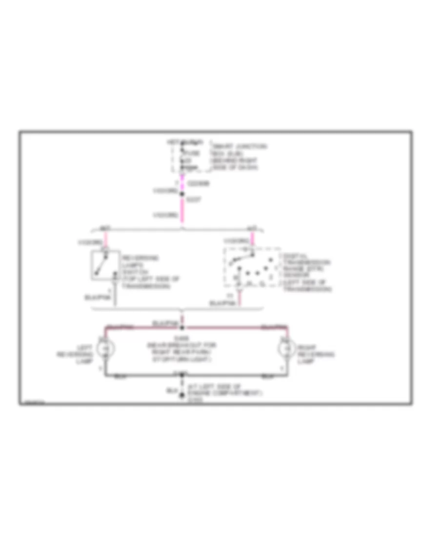
Back-up Lamps Wiring Diagram for Ford Ranger 2006
 https://portal-diagnostov.com/license.html
Automotive Electricians Portal FZCO
Automotive Electricians Portal FZCO
https://portal-diagnostov.com/license.html
https://portal-diagnostov.com/license.html
Automotive Electricians Portal FZCO
Automotive Electricians Portal FZCOList of elements for Back-up Lamps Wiring Diagram for Ford Ranger 2006:
- (at left side of engine compartment) g103
- A/t
- C2280b
- Digital transmission range (dtr) sensor (left side of transmission)
- Fuse 10a
- Hot in run
- Left reversing lamp
- M/t
- Reversing lamps switch (top left side of transmission)
- Right reversing lamp
- S237
- S406
- S408 (near breakout for right rear park/ stop/turn light)
- Smart junction box (sjb) (behind right side of dash)
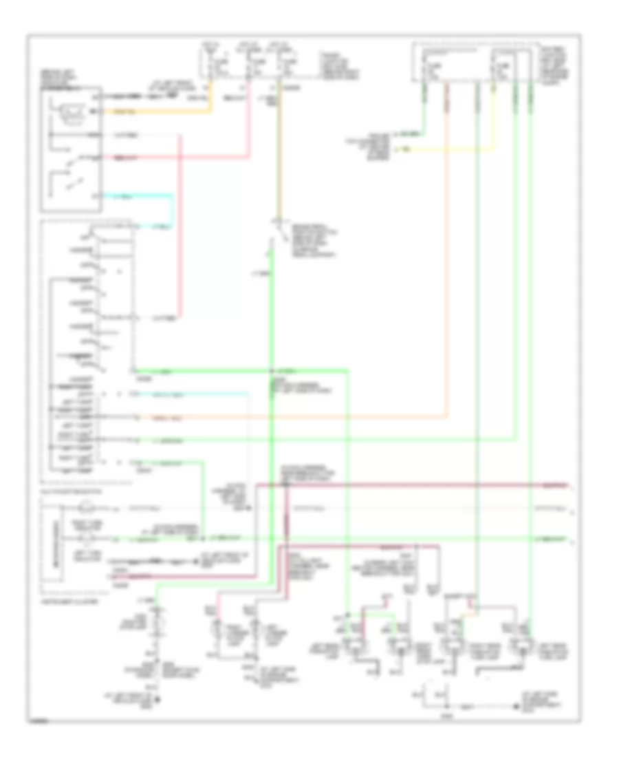
Exterior Lamps Wiring Diagram (1 of 2) for Ford Ranger 2006
 https://portal-diagnostov.com/license.html
Automotive Electricians Portal FZCO
Automotive Electricians Portal FZCO
https://portal-diagnostov.com/license.html
https://portal-diagnostov.com/license.html
Automotive Electricians Portal FZCO
Automotive Electricians Portal FZCOList of elements for Exterior Lamps Wiring Diagram (1 of 2) for Ford Ranger 2006:
- (at left front of vehicle floor) g205
- (at left side of engine compartment) g103
- (behind left side of dash) indicator flasher relay
- (in main harness, at left side of dash) s207
- (in main harness, at left side of dash) s211
- (in main harness, near breakout for left side of dash) s214
- (in rear light con- nector harness, near breakout for c421)
- 87a
- Battery junction box (bjb) (at left rear side of engine compt)
- Brake pedal position switch (behind left side of dash, on brake pedal support)
- C202a
- C202b
- C220a
- C220b
- C2280b
- Except stx
- Fuse 10a
- Fuse 15a
- Fuse 20a
- Fuse 7.5a
- Hazard
- High mounted stoplamp
- Hot at all times
- Hot in run
- Instrument cluster
- Left license plate lamp
- Left rear park/stop lamp
- Left rear park/stop/ turn lamp
- Left turn
- Left turn indicator
- Microprocessor
- Multi-function switch
- Off
- Right license plate lamp
- Right rear park/ stop lamp
- Right rear park/stop/ turn lamp
- Right turn
- Right turn indicator
- S203
- S206
- S206 (except four- door model)
- S404 (in taillight harness, near breakout for c421)
- S405
- S406
- S407
- S409 (four-door model)
- S411
- Smart junction box (sjb) (behind right side of dash)
- Stx
- Trailer tow connector (at center of rear bumper)
Exterior Lamps Wiring Diagram (2 of 2) for Ford Ranger 2006
 https://portal-diagnostov.com/license.html
Automotive Electricians Portal FZCO
Automotive Electricians Portal FZCO
https://portal-diagnostov.com/license.html
https://portal-diagnostov.com/license.html
Automotive Electricians Portal FZCO
Automotive Electricians Portal FZCOList of elements for Exterior Lamps Wiring Diagram (2 of 2) for Ford Ranger 2006:
- (at left side of engine compt) g103
- (at right rear of engine compt) g105
- (near right headlight) s121
- C2280a
- C2280c
- C2280d
- Fuse 10a
- Fuse 20a
- Fuse 5a
- G204 (under front of center console)
- G205 (at left front of vehicle floor)
- Head
- Hot at all times
- Interior lights system
- Left front park/turn lamp
- Left front side lamp
- Left rear turn lamp (w/ stx)
- Low current board
- Main light switch
- Off
- Park
- Park lamp relay
- Right front park/turn lamp
- Right front side lamp
- Right rear turn lamp (w/ stx)
- S119
- S123
- S162
- S163
- S209
- S236
- S406
- Smart junction box (sjb) (behind right side of dash)
- Trailer/ camper adapter circuit
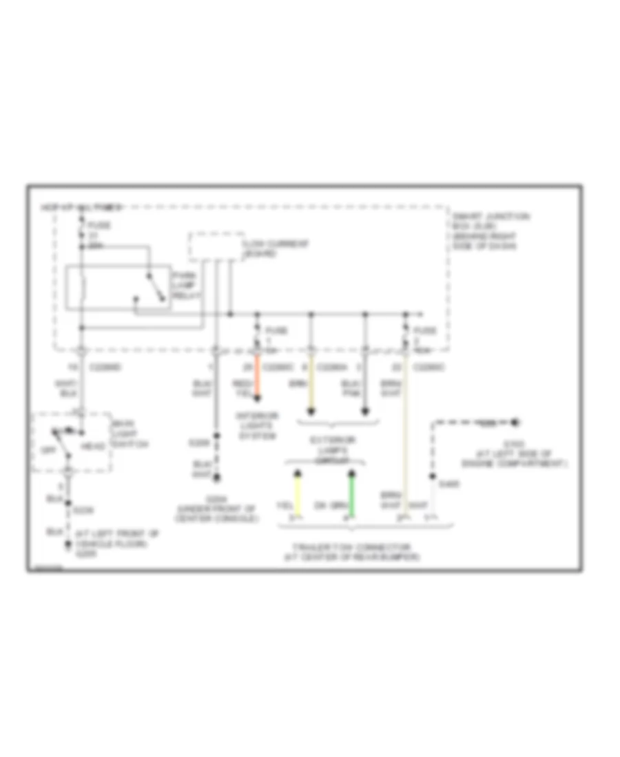
Trailer Tow Wiring Diagram for Ford Ranger 2006
 https://portal-diagnostov.com/license.html
Automotive Electricians Portal FZCO
Automotive Electricians Portal FZCO
https://portal-diagnostov.com/license.html
https://portal-diagnostov.com/license.html
Automotive Electricians Portal FZCO
Automotive Electricians Portal FZCOList of elements for Trailer Tow Wiring Diagram for Ford Ranger 2006:
- (at left front of vehicle floor) g205
- C2280a
- C2280c
- C2280d
- Exterior lamps circuit
- Fuse 10a
- Fuse 20a
- Fuse 5a
- G103 (at left side of engine compartment)
- G204 (under front of center console)
- Head
- Hot at all times
- Interior lights system
- Low current board
- Main light switch
- Off
- Park
- Park lamp relay
- S209
- S236
- S405
- Smart junction box (sjb) (behind right side of dash)
- Trailer tow connector (at center of rear bumper)
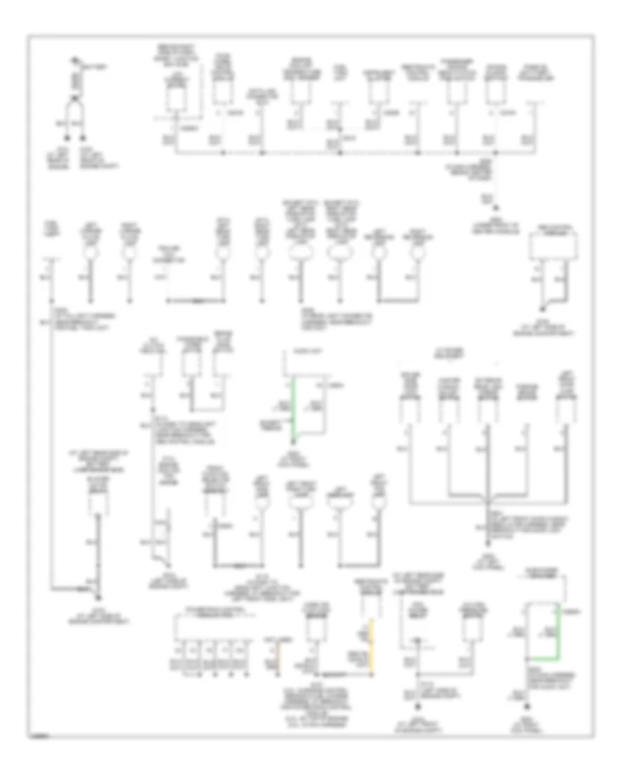
GROUND DISTRIBUTION
Ground Distribution Wiring Diagram (1 of 2) for Ford Ranger 2006
 https://portal-diagnostov.com/license.html
Automotive Electricians Portal FZCO
Automotive Electricians Portal FZCO
https://portal-diagnostov.com/license.html
https://portal-diagnostov.com/license.html
Automotive Electricians Portal FZCO
Automotive Electricians Portal FZCOList of elements for Ground Distribution Wiring Diagram (1 of 2) for Ford Ranger 2006:
- (2.3l) engine cooling fan motor
- (at left rear side of engine compt) battery junction box (bjb)
- (behind right side of dash) smart junction box (sjb)
- (except stx) left rear park/stop turn lamp (stx) left rear park/stop lamp
- (except stx) right rear park/stop/ turn lamp (stx) right rear park/stop lamp
- (not used)
- (stx) left rear turn lamp
- (stx) right rear turn lamp
- A/c clutch field coil
- A/c high pressure switch
- Abs control module
- Air bag sliding contact
- Audio unit
- Battery
- Blower motor relay
- Brake fluid level switch
- C218a
- C220b
- C2280c
- C281b
- C290a
- C294c
- C2982a
- Data link connector (dlc)
- Driver side door lock switch
- Engine coolant temperature (ect) sender
- Except tremor
- Exterior rear view mirror switch
- For fuel tank unit)
- Four- wheel drive control module
- Front function selector switch assembly
- Fuel tank unit
- G100 (at left front of engine compt)
- G101 (at left rear of engine)
- G102 (at left side of engine compartment)
- G103 (at left side of engine compartment)
- G104 (at left front of engine compt)
- G200 (at left kick panel)
- G202 (at right kick panel)
- G203 (at right kick panel)
- G204 (under front of center console)
- Instrument cluster
- Junction harness, near breakout for abs control module)
- Left front door ajar switch
- Left front fog lamp
- Left front park/turn lamp
- Left front side lamp
- Left headlamp
- Left license plate lamp
- Left reversing lamp
- Low current board
- Mass air flow (maf) sensor
- Master window adjust switch
- Nca
- Parking brake switch
- Passenger air bag deactivation (pad) switch
- Passive anti-theft transceiver
- Pcm power relay
- Powertrain control module (pcm)
- Restraints control module
- Right license plate lamp
- Right reversing lamp
- S107 (4.0l: in engine control sensor & fuel charge harness, at breakout for powertrain control module) (2.3l: on top of engine) (3.0l: in pcm harness)
- S108 (left side of engine compt)
- S118 (left side of engine compt)
- S119 (in dash to headlight junction harness, at breakout for left front side light)
- S209 (in main harness, behind center of dash)
- S215
- S230 (in main harness, near breakout for audio unit)
- S406 (in rear light connector harness, near breakout for c421)
- Subwoofer amplifier
- Trailer tow connector
- W/ power equipment
- Windshield wiper motor
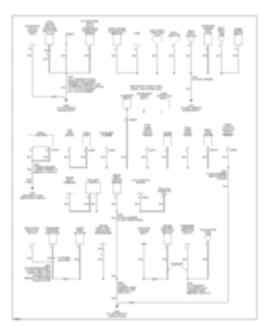
Ground Distribution Wiring Diagram (2 of 2) for Ford Ranger 2006
 https://portal-diagnostov.com/license.html
Automotive Electricians Portal FZCO
Automotive Electricians Portal FZCO
https://portal-diagnostov.com/license.html
https://portal-diagnostov.com/license.html
Automotive Electricians Portal FZCO
Automotive Electricians Portal FZCOList of elements for Ground Distribution Wiring Diagram (2 of 2) for Ford Ranger 2006:
- (3.0l) heated positive crankcase ventilation valve
- (behind right side of dash) smart junction box (sjb)
- (w/ four-wheel drive) digital transmission range (dtr) sensor
- Accessory relay
- Audio unit
- Blend door actuator
- Brake pedal position switch
- Brake shift interlock
- C202a
- C2031b
- C220a
- C2280c
- C281a
- C290a
- C294b
- C3154a
- Data link connector (dlc)
- Door lock/unlock relay
- Driver door unlock relay
- Driver safety belt retractor pretensioner
- Driver side rear door ajar switch
- Fog lamp switch
- Four- wheel drive control module
- Four- wheel drive switch
- Four-door
- Front cigar lighter
- Front function selector switch assembly
- Front heater blower motor resistor
- G105 (at right rear of engine compt)
- G106 (at top rear of engine compt)
- G205 (at left front of vehicle floor)
- G300 (center of floor, behind front seats)
- High mounted stop lamp
- Horn
- Indicator flasher relay
- Instrument cluster
- Main light switch
- Multi-function switch
- Nca
- Passenger side door lock switch
- Passenger side rear door ajar switch
- Power point
- Powertrain control module (pcm)
- Radio amplifier
- Right front door ajar switch
- Right front fog lamp
- Right front park/turn lamp
- Right front side lamp
- Right headlamp
- S123 (at right fender)
- S145 (4.0l: in engine control sensor & fuel charge harness, at breakout for powertrain control module) (2.3l: on top of engine) (3.0l: in pcm harness)
- S203 (in main harness, behind center of dash)
- S206 (in main harness, near breakout for audio unit)
- S300 (in radio speaker jumper harness, at breakout for c314)
- S409 (w/ four-door) (in interior light harness, near breakout for c710)
- S600 (w/ power equipment) (in right front door window regulator harness, near breakout for power window motor)
- Shield
- Speed control servo
- W/ power equipment
- Windshield washer pump motor
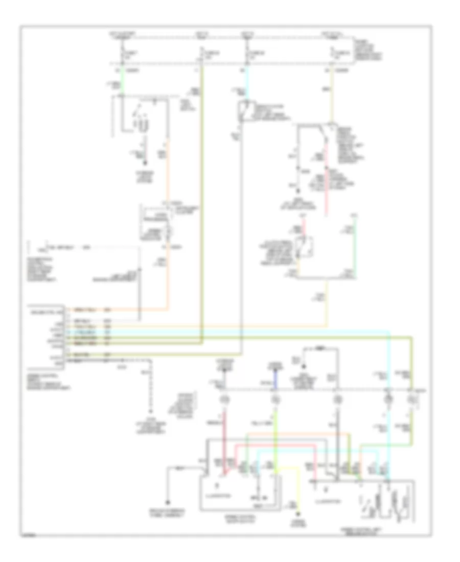
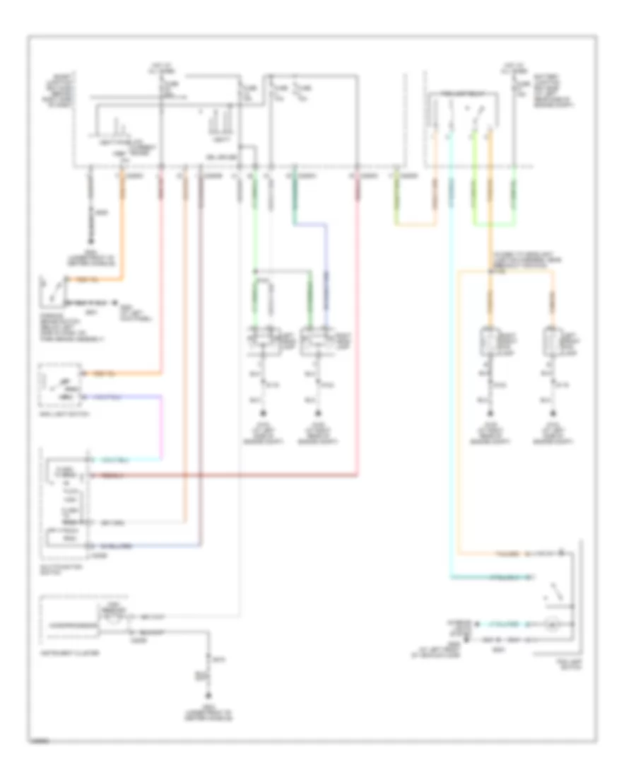
HEADLIGHTS
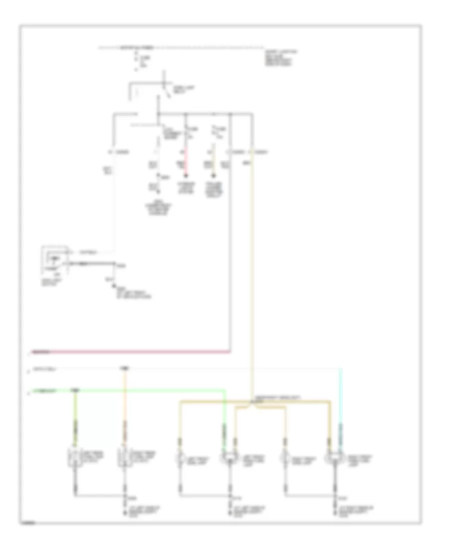
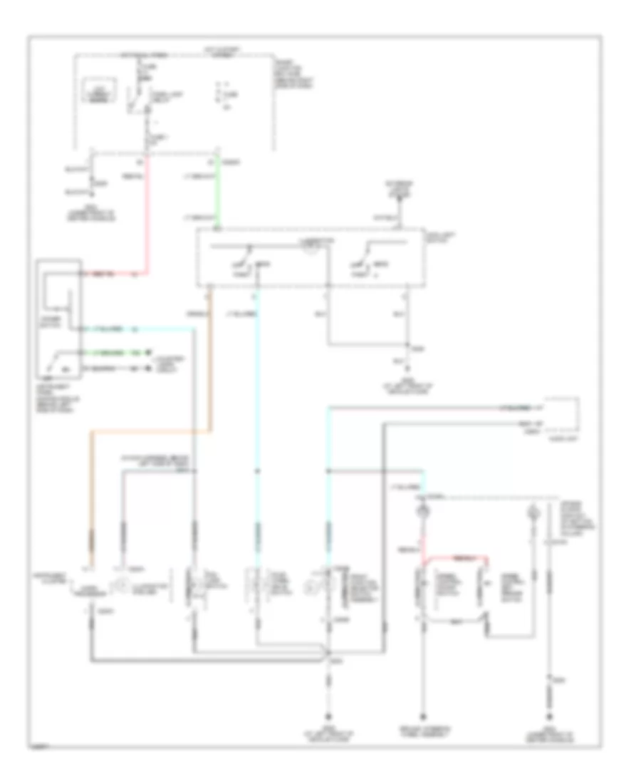
Headlights Wiring Diagram, with DRL for Ford Ranger 2006
 https://portal-diagnostov.com/license.html
Automotive Electricians Portal FZCO
Automotive Electricians Portal FZCO
https://portal-diagnostov.com/license.html
https://portal-diagnostov.com/license.html
Automotive Electricians Portal FZCO
Automotive Electricians Portal FZCOList of elements for Headlights Wiring Diagram, with DRL for Ford Ranger 2006:
- (in dash to headlight junction harness, near breakout for g102) s122
- Battery junction box (bjb) (at left rear side of engine compt)
- C202b
- C220b
- C2280a
- C2280c
- Drl driver
- Flash to pass
- Fog lamp relay
- Fog lamp switch
- Fuse 10a
- Fuse 15a
- Fuse 30a
- G103 (at left side of engine compt)
- G105 (at right rear of engine compt)
- G200 (at left kick panel)
- G204 (under front of center console)
- G205 (at left front of vehicle floor)
- Head
- High
- High beam ind
- Hot at all times
- Instrument cluster
- Interior lights system
- Left front fog lamp
- Left head- lamp
- Low
- Low current board
- Main light switch
- Microprocessor
- Multi-function switch
- Off
- Park
- Parking brake switch (below left side of dash, on park brake assembly)
- Pwr
- Right front fog lamp
- Right head- lamp
- S102
- S119
- S123
- S203
- S209
- S215
- S501
- Smart junction box (sjb) (behind right side of dash)
- Vbatt
- Vref
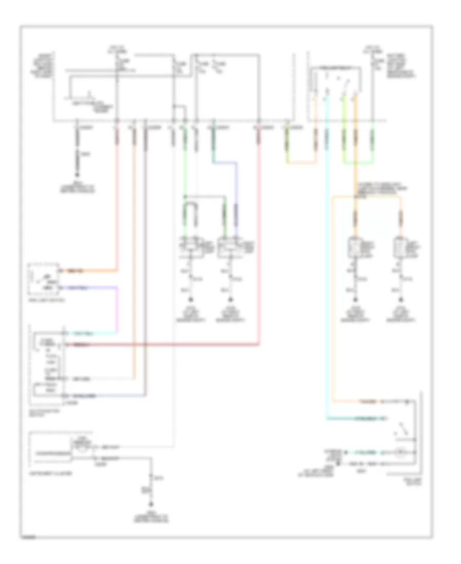
Headlights Wiring Diagram, without DRL for Ford Ranger 2006
 https://portal-diagnostov.com/license.html
Automotive Electricians Portal FZCO
Automotive Electricians Portal FZCO
https://portal-diagnostov.com/license.html
https://portal-diagnostov.com/license.html
Automotive Electricians Portal FZCO
Automotive Electricians Portal FZCOList of elements for Headlights Wiring Diagram, without DRL for Ford Ranger 2006:
- (in dash to headlight junction harness, near breakout for g102) s122
- Battery junction box (bjb) (at left rear side of engine compt)
- C202b
- C220b
- C2280a
- C2280c
- Flash to pass
- Fog lamp relay
- Fog lamp switch
- Fuse 10a
- Fuse 15a
- Fuse 30a
- G103 (at left side of engine compt)
- G105 (at right rear of engine compt)
- G204 (under front of center console)
- G205 (at left front of vehicle floor)
- Head
- High
- High beam ind
- Hot at all times
- Instrument cluster
- Interior lights system
- Left front fog lamp
- Left head- lamp
- Low
- Low current board
- Main light switch
- Microprocessor
- Multi-function switch
- Off
- Park
- Pwr
- Right front fog lamp
- Right head- lamp
- S119
- S123
- S203
- S209
- S215
- Smart junction box (sjb) (behind right side of dash)
- Vbatt
HORN
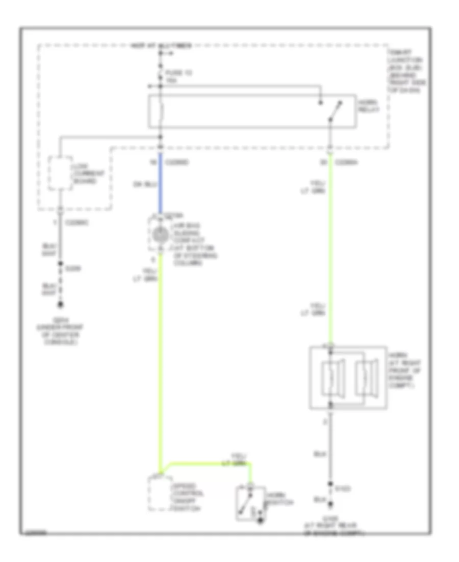
Horn Wiring Diagram for Ford Ranger 2006
 https://portal-diagnostov.com/license.html
Automotive Electricians Portal FZCO
Automotive Electricians Portal FZCO
https://portal-diagnostov.com/license.html
https://portal-diagnostov.com/license.html
Automotive Electricians Portal FZCO
Automotive Electricians Portal FZCOList of elements for Horn Wiring Diagram for Ford Ranger 2006:
- Air bag sliding contact (at bottom of steering column)
- C218a
- C2280a
- C2280c
- C2280d
- Fuse 13 15a
- G105 (at right rear
- G204 (under front of center console)
- Horn (at right front of engine compt)
- Horn relay
- Horn switch
- Hot at all times
- Low current board
- Of engine compt)
- Off
- S123
- S209
- Smart junction box (sjb) (behind right side of dash)
- Speed control on/off switch
INSTRUMENT CLUSTER
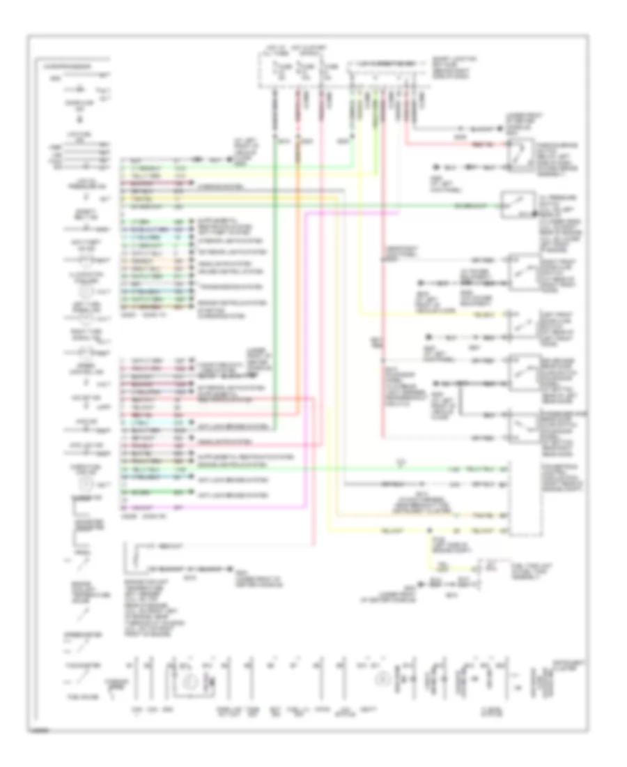
Instrument Cluster Wiring Diagram for Ford Ranger 2006
 https://portal-diagnostov.com/license.html
Automotive Electricians Portal FZCO
Automotive Electricians Portal FZCO
https://portal-diagnostov.com/license.html
https://portal-diagnostov.com/license.html
Automotive Electricians Portal FZCO
Automotive Electricians Portal FZCOList of elements for Instrument Cluster Wiring Diagram for Ford Ranger 2006:
- (at left front of vehicle floor) g205
- (conn "a")
- (conn "b")
- (near right kick panel) s234
- (under front of center console) g204
- (w/ power equipment) s600
- 2.3l
- 4wd ind
- 4wd low ind
- 4x4 status
- A10
- A11
- A12
- A13
- A14
- A15
- A16
- A17
- A18
- A19
- A20
- Abs ind
- Air bag ind
- Anti-lock brakes system
- Anti-theft on ind
- B10
- B11
- B12
- B13
- B14
- B15
- B16
- B18
- B20
- C220a
- C220b
- C2280b
- C2280c
- C2280d
- Can +
- Can -
- Charge ind
- Check engine ind
- Check fuel cap ind
- Computer data lines system
- Cruise control system
- Door ajar ind
- Driver side rear door ajar switch (four-door model) (at bottom rear of left rear door)
- Ect sig
- Engine controls system
- Engine coolant temperature (ect) sender (2.3l: on top rear of engine) (3.0l: on front left of engine, near thermostat housing) (4.0l: on top right front of engine)
- Engine coolant temperature gauge
- Exterior lights system
- F level status
- Failsafe cooling ind
- Fuel gauge
- Fuel lvl sig
- Fuel tank unit (in fuel tank assembly)
- Fuse 10a
- Fuse 5a
- G200 (at left kick panel)
- G204 (under front of center console)
- G205 (at left front of vehicle floor)
- Gnd
- Headlights system
- High beam ind
- Hot at all times
- Hot in start or run
- Illumination (6 bulbs)
- Instrument cluster
- Interior lights system
- Left front door ajar switch (at rear of left front door)
- Left turn signal ind
- Low brake fluid level/park brake ind
- Low current board
- Low fuel ind
- Low oil pressure ind
- Microprocessor
- O/d off ind
- Odometer/ tripmeter
- Oil pressure switch (2.3l: on left rear of cylinder head) (3.0l: on right rear of engine) (4.0l: on lower left front of engine)
- Park lmp rly out
- Parking brake switch (below left side of dash, on park brake assembly)
- Passenger side rear door ajar switch (four-door model) (at bottom rear right rear door)
- Powertrain control module (pcm) (right rear of engine compt)
- Prndl
- Right front door ajar switch (at rear of right front door)
- Right turn signal ind
- S125 (left side of engine compt)
- S203
- S206 (w/o power equipment)
- S209
- S213 (in main harness, near breakout for instrument cluster)
- S215
- S218
- S220
- S223
- S410 (four-door model) (in interior light harness, near breakout for c710)
- S501
- Safety belt ind
- Smart junction box (sjb) (behind right side of dash)
- Speed control ind
- Speedometer
- Starting/ charging system
- Tach sig
- Tachometer
- Tone sig
- Transmissions system
- Vbatt
- Vpwr
- Vref
- Vss
- Warning chime
- Warning system
INTERIOR LIGHTS
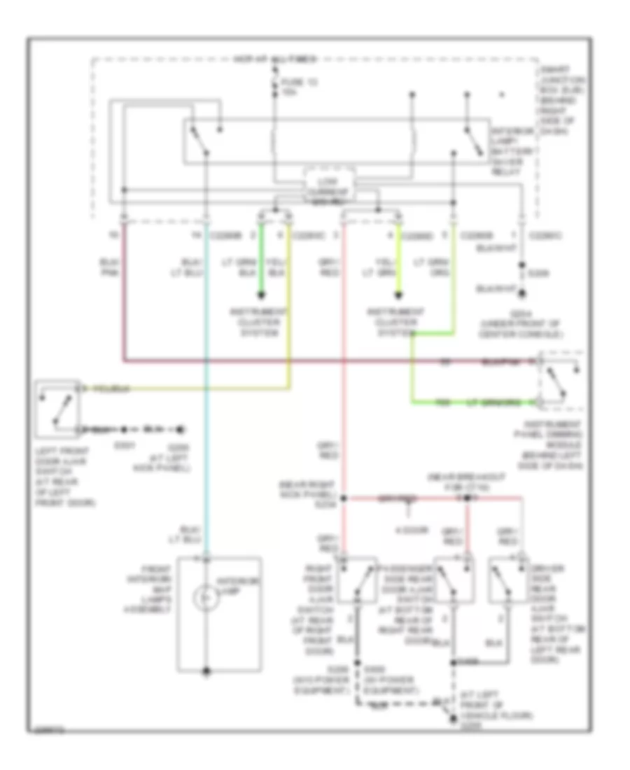
Courtesy Lamps Wiring Diagram for Ford Ranger 2006
 https://portal-diagnostov.com/license.html
Automotive Electricians Portal FZCO
Automotive Electricians Portal FZCO
https://portal-diagnostov.com/license.html
https://portal-diagnostov.com/license.html
Automotive Electricians Portal FZCO
Automotive Electricians Portal FZCOList of elements for Courtesy Lamps Wiring Diagram for Ford Ranger 2006:
- (at left front of vehicle floor) g205
- (near breakout for c710) s410
- (near right kick panel) s234
- 4 door
- C2280b
- C2280c
- C2280d
- Driver side rear door ajar switch (at bottom rear of left rear door)
- Front interior/ map lamps assembly
- Fuse 13 15a
- G200 (at left kick panel)
- G204 (under front of center console)
- Hot at all times
- Instrument cluster system
- Instrument panel dimming module (behind left side of dash)
- Interior lamp
- Interior lamp/ battery saver relay
- Left front door ajar switch (at rear of left front door)
- Low current board
- Passenger side rear door ajar switch (at bottom rear of right rear door)
- Right front door ajar switch (at rear of right front door)
- S206 (w/o power equipment)
- S209
- S409
- S501
- S600 (w/ power equipment)
- Smart junction box (sjb) (behind right side of dash)
Instrument Illumination Wiring Diagram for Ford Ranger 2006
 https://portal-diagnostov.com/license.html
Automotive Electricians Portal FZCO
Automotive Electricians Portal FZCO
https://portal-diagnostov.com/license.html
https://portal-diagnostov.com/license.html
Automotive Electricians Portal FZCO
Automotive Electricians Portal FZCOList of elements for Instrument Illumination Wiring Diagram for Ford Ranger 2006:
- (in main harness, behind left side of dash) s217
- Air bag sliding contact (at bottom of steering column)
- Audio unit
- C218a
- C220a
- C2280c
- C290a
- C294b
- Courtesy lamps circuit
- Dimmer
- Exterior lights system
- Fog lamp switch
- Four- wheel drive switch
- Front function selector switch assembly
- Fuse
- Fuse 1 5a
- Fuse 20a
- G204 (under front of center console)
- G205 (at left front of vehicle floor)
- Ground, steering wheel assembly
- Head
- Hot at all times
- Hot in start or run
- Illumination
- Illumination (6 bulbs)
- Instrument cluster
- Instrument panel dimming module (behind left side of dash)
- Low current board
- Main light switch
- Micro- processor
- Off
- Park
- Park lamp relay
- S203
- S209
- S236
- Smart junction box (sjb) (behind right side of dash)
- Speed control on/off switch
- Speed control set/ resume switch
- Switch
POWER DISTRIBUTION
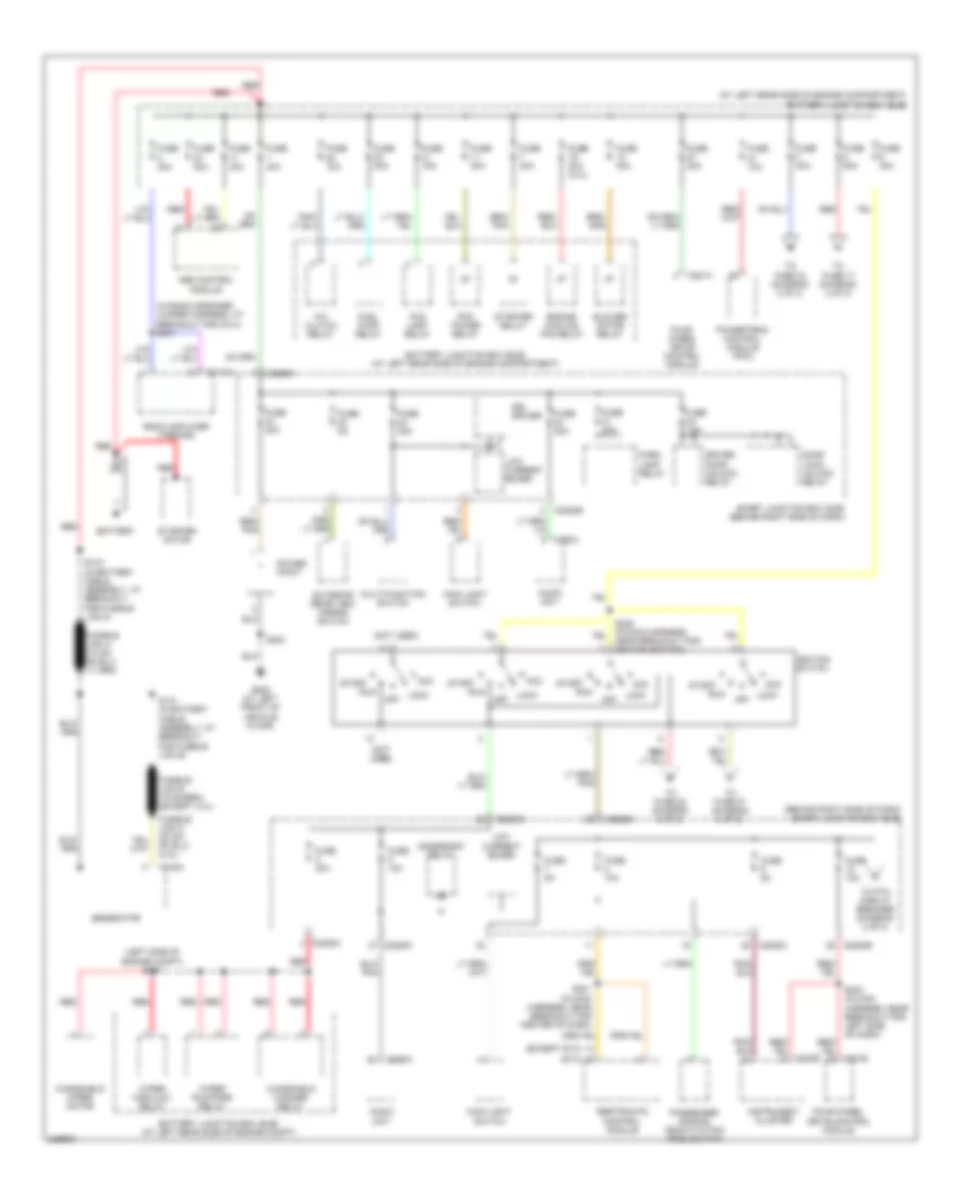
Power Distribution Wiring Diagram (1 of 2) for Ford Ranger 2006
 https://portal-diagnostov.com/license.html
Automotive Electricians Portal FZCO
Automotive Electricians Portal FZCO
https://portal-diagnostov.com/license.html
https://portal-diagnostov.com/license.html
Automotive Electricians Portal FZCO
Automotive Electricians Portal FZCOList of elements for Power Distribution Wiring Diagram (1 of 2) for Ford Ranger 2006:
- (at left rear side of engine compartment) battery junction box (bjb)
- (behind right side of dash) smart junction box (sjb)
- (except stx)
- (in radio speaker jumper harness, at breakout for c314) s301
- (left side of engine compt) s127
- (not used)
- (stx)
- A/c clutch relay
- Abs control module
- Acc
- Accessory relay
- Audio unit
- Battery
- Battery junction box (bjb) (at left rear side of engine compartment)
- Battery junction box (bjb) (at left rear side of engine compt)
- Blower motor relay
- C102a
- C220b
- C2280a
- C2280b
- C2280c
- C281a
- C281b
- C290a
- C3154a
- Door lock/ unlock relay
- Driver door unlock relay
- Drl driver
- Engine cooling fan relay
- Exterior rear view mirror switch
- Fog lamp relay
- Four- wheel drive control module
- Four-wheel drive control module
- Fuel pump relay
- Fuse 10a
- Fuse 15a
- Fuse 20a
- Fuse 20a (2.3l)
- Fuse 30a
- Fuse 40a
- Fuse 50a
- Fuse 5a
- G205 (at left front of vehicle floor)
- Generator
- Ignition switch
- Instrument cluster
- Lock
- Low current board
- Main light switch
- Multi-function switch
- Off
- Park lamp relay
- Passenger air bag deactivation (pad) switch
- Pcm power relay
- Power point
- Powertrain control module (pcm)
- Radio amplifier (tremor)
- Red
- Restraints control module
- Run
- S130 (in battery cable assembly, at breakout for fusible link a)
- S131 (in battery cable assembly, at breakout for fusible link b)
- S201 (in main harness, near breakout for center of dash)
- S203
- S223 (in main harness, near breakout for left side of dash)
- S228 (in main harness, near breakout for ignition switch)
- Smart junction box (sjb) (behind right side of dash)
- Start
- Starter motor
- Starter relay
- To fuse 17 (diagram 2 of 2)
- To fuse 22 (diagram 2 of 2)
- To fuse 27 (diagram 2 of 2)
- To fuse 33 (diagram 2 of 2)
- To ptc circuit breaker (diagram 2 of 2)
- Windshield washer relay
- Windshield wiper motor
- Wiper high/low relay
- Wiper run/park relay
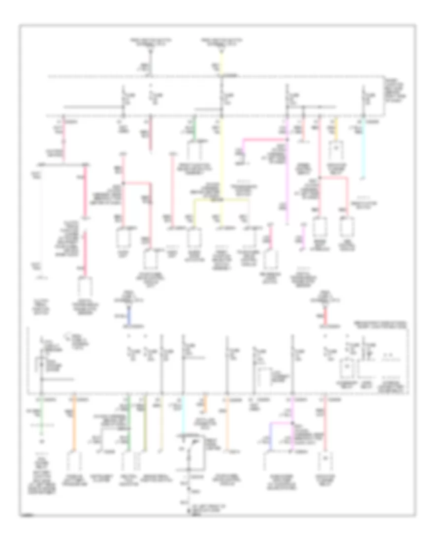
Power Distribution Wiring Diagram (2 of 2) for Ford Ranger 2006
 https://portal-diagnostov.com/license.html
Automotive Electricians Portal FZCO
Automotive Electricians Portal FZCO
https://portal-diagnostov.com/license.html
https://portal-diagnostov.com/license.html
Automotive Electricians Portal FZCO
Automotive Electricians Portal FZCOList of elements for Power Distribution Wiring Diagram (2 of 2) for Ford Ranger 2006:
- (at left front of vehicle floor) g205
- (behind right side of dash) smart junction box (sjb)
- (in main harness, at left side of dash)
- (in main harness, behind center of dash) s216
- (in main harness, behind left side of dash) s218
- (not used)
- 4x2
- 4x4
- A/t
- Abs control module
- Accessory relay
- Audio unit
- Battery junction box (bjb) (at left rear side of engine compartment)
- Blend door actuator
- Brake pedal position switch
- Brake shift interlock
- C2031a
- C2031b
- C220b
- C2280a
- C2280b
- C2280c
- C2280d
- C281a
- C290a
- C294a
- C2982a
- Clutch pedal position switch
- Clutch triple function jumper (w/ power equipment four-wheel drive & base audio)
- Data link connector (dlc)
- Deactivator switch
- Digital transmission range (dtr) sensor
- Four-wheel drive control module
- Four-wheel drive control module (m/t)
- From fuse 3 (diagram 1 of 2)
- From fuse 5 (diagram 1 of 2)
- From fuse 10 (diagram 1 of 2)
- From ignition switch (diagram 1 of 2)
- Front cigar lighter
- Front function selector switch assembly
- Fuse 10a
- Fuse 15a
- Fuse 20a
- Fuse 2a
- Fuse 30a
- Fuse 5a
- Horn relay
- Indicator flasher relay
- Instrument cluster
- Interior lamp/battery saver relay
- Low current board
- M/t
- Nca
- Neutral tow indicator
- Off
- Passive anti-theft transceiver
- Pcm power diode
- Pcm power relay
- Pnk
- Ptc circuit breaker 1a
- Red
- Reversing lamps switch
- S200 (in main harness, near breakout for center of dash)
- S203
- S221
- S237 (in main harness, at left side of dash)
- Smart junction box (sjb) (behind right side of dash)
- Speed control servo
- Subwoofer amplifier (w/ audiophile sound system)
- Transmission control switch
POWER DOOR LOCKS
Power Door Locks Wiring Diagram for Ford Ranger 2006
 https://portal-diagnostov.com/license.html
Automotive Electricians Portal FZCO
Automotive Electricians Portal FZCO
https://portal-diagnostov.com/license.html
https://portal-diagnostov.com/license.html
Automotive Electricians Portal FZCO
Automotive Electricians Portal FZCOList of elements for Power Door Locks Wiring Diagram for Ford Ranger 2006:
- (at left front of vehicle floor)
- C2280a
- C2280b
- C2280c
- C2280d
- Data link connector (dlc) (at bottom of steering column)
- Door lock/
- Driver door unlock relay
- Driver side door lock switch
- Driver side rear door ajar switch (4 door) (at bottom rear of left rear door)
- Exterior lights system
- Fuse 10a
- Fuse 15a
- Fuse 20a
- Fuse 5a
- G200 (at left kick panel)
- G204 (under front of center console)
- G205
- G205 (at left front of vehicle floor)
- Horn relay
- Horns system
- Hot at all times
- Instrument cluster system
- Interior lights system
- Left front door ajar switch (w/o power equipment: (at rear of left front door)
- Left front door lock actuator (w/ power equipment: at rear of left front door)
- Lock
- Low current board
- Main light switch
- Park lamp relay
- Passenger side door lock switch
- Passenger side rear door ajar switch (4 door) (at bottom rear right rear door)
- Red
- Right front door ajar switch (w/o power equipment: (at rear of right front door)
- Right front door lock actuator (w/ power equipment: at rear of right front door)
- S203
- S209
- S234 (near right kick panel)
- S409
- S410 (w/ 4 door) (in interior light harness, near breakout for c710)
- S501
- S600
- S600 (w/ power equipment)
- Smart junction box (sjb) (behind right side of dash)
- Unlock
- Unlock relay
POWER MIRRORS
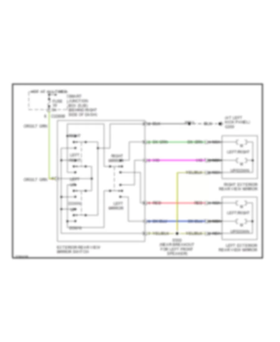
Power Mirrors Wiring Diagram for Ford Ranger 2006
 https://portal-diagnostov.com/license.html
Automotive Electricians Portal FZCO
Automotive Electricians Portal FZCO
https://portal-diagnostov.com/license.html
https://portal-diagnostov.com/license.html
Automotive Electricians Portal FZCO
Automotive Electricians Portal FZCOList of elements for Power Mirrors Wiring Diagram for Ford Ranger 2006:
- (at left kick panel) g200
- C2280b
- Down
- Exterior rear view mirror switch
- Fuse 5a
- Hot at all times
- Left
- Left exterior rear view mirror
- Left mirror
- Left/right
- Nca
- Red
- Right
- Right exterior rear view mirror
- Right mirror
- S501
- S502 (near breakout for left front speaker)
- Smart junction box (sjb) (behind right side of dash)
- Up/down
POWER WINDOWS
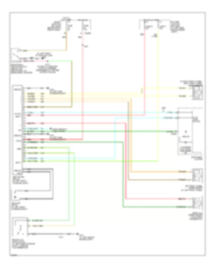
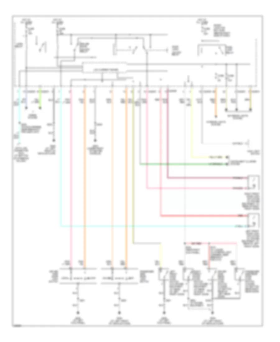
Power Windows Wiring Diagram for Ford Ranger 2006
 https://portal-diagnostov.com/license.html
Automotive Electricians Portal FZCO
Automotive Electricians Portal FZCO
https://portal-diagnostov.com/license.html
https://portal-diagnostov.com/license.html
Automotive Electricians Portal FZCO
Automotive Electricians Portal FZCOList of elements for Power Windows Wiring Diagram for Ford Ranger 2006:
- (at center of left front door) driver side front power window motor
- (at center of right front door)
- (in left front door window regulator harness, near breakout for exterior rearview mirror) s500
- 11a
- Accessory relay
- C2280c
- C2280d
- Down
- Driver
- Fuse 10a
- Fuse 30a
- G200 (at left kick panel)
- G204 (under front of center console)
- G205 (at left front of vehicle floor)
- Hot at all times
- Hot in run or acc
- Low current board
- Master window adjust switch
- Off
- One-touch window relay
- Passenger
- Passenger side front power window motor
- Passenger side window adjust switch
- Ptc circuit breaker
- Red
- Resistor
- Rest
- S203
- S209
- S501
- Smart junction box (sjb) (behind right side of dash)
RADIO
Audiophile Sound Radio Wiring Diagram for Ford Ranger 2006
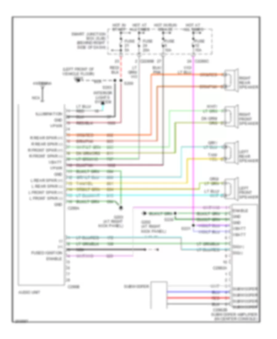 https://portal-diagnostov.com/license.html
Automotive Electricians Portal FZCO
Automotive Electricians Portal FZCO
https://portal-diagnostov.com/license.html
https://portal-diagnostov.com/license.html
Automotive Electricians Portal FZCO
Automotive Electricians Portal FZCOList of elements for Audiophile Sound Radio Wiring Diagram for Ford Ranger 2006:
- (+)
- (-)
- (left front of vehicle floor) g205
- Antenna
- Audio unit
- C2280b
- C2280c
- C290a
- C290b
- C2982a
- C2982b
- Enable
- Fuse 10a
- Fuse 15a
- Fuse 20a
- Fuse 5a
- Fused ignition
- G202 (at right kick panel)
- G203 (at right kick panel)
- Gnd
- Hot at all times
- Hot in run or acc
- Hot in start
- Illumination
- Interior lights system
- L front spkr (+)
- L front spkr (-)
- L rear spkr (+)
- L rear spkr (-)
- Left front speaker
- Left rear speaker
- Nca
- R front spkr (+)
- R front spkr (-)
- R rear spkr (+)
- R rear spkr (-)
- Red
- Right front speaker
- Right rear speaker
- S200
- S203
- S230
- S231
- Sig(+)
- Sig(-)
- Smart junction box (sjb) (behind right side of dash)
- Subwoofer
- Subwoofer amplifier (in center console)
- Vbatt
- Vpwr
Base Radio Wiring Diagram for Ford Ranger 2006
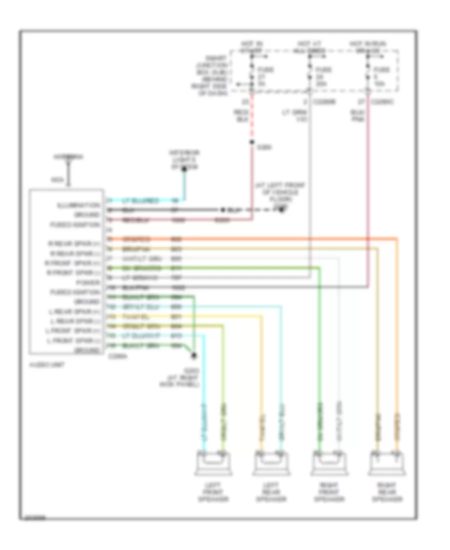 https://portal-diagnostov.com/license.html
Automotive Electricians Portal FZCO
Automotive Electricians Portal FZCO
https://portal-diagnostov.com/license.html
https://portal-diagnostov.com/license.html
Automotive Electricians Portal FZCO
Automotive Electricians Portal FZCOList of elements for Base Radio Wiring Diagram for Ford Ranger 2006:
- (at left front of vehicle floor) g205
- Antenna
- Audio unit
- C2280b
- C2280c
- C290a
- Fuse 10a
- Fuse 20a
- Fuse 5a
- Fused ignition
- G203 (at right kick panel)
- Ground
- Hot at all times
- Hot in run or acc
- Hot in start
- Illumination
- Interior lights system
- L front spkr (+)
- L front spkr (-)
- L rear spkr (+)
- L rear spkr (-)
- Left front speaker
- Left rear speaker
- Nca
- Power
- R front spkr (+)
- R front spkr (-)
- R rear spkr (+)
- R rear spkr (-)
- Right front speaker
- Right rear speaker
- S200
- S203
- Smart junction box (sjb) (behind right side of dash)
Tremor Audio Radio Wiring Diagram for Ford Ranger 2006
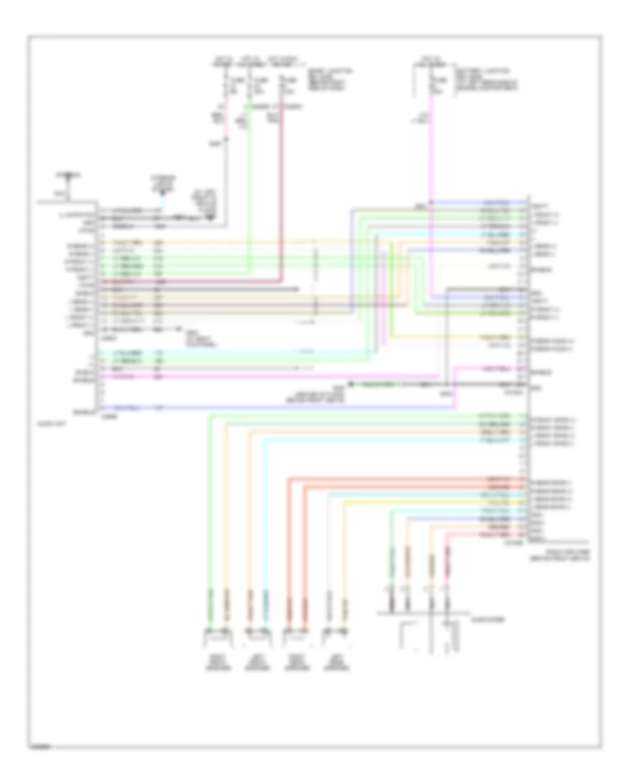 https://portal-diagnostov.com/license.html
Automotive Electricians Portal FZCO
Automotive Electricians Portal FZCO
https://portal-diagnostov.com/license.html
https://portal-diagnostov.com/license.html
Automotive Electricians Portal FZCO
Automotive Electricians Portal FZCOList of elements for Tremor Audio Radio Wiring Diagram for Ford Ranger 2006:
- (+)
- (-)
- (at left front of vehicle floor) g205
- Antenna
- Audio unit
- Battery junction box (bjb) (at left rear side of engine compartment)
- C2280b
- C2280c
- C290a
- C290b
- C3154a
- C3154b
- Enable
- Fuse 10a
- Fuse 20a
- Fuse 40a
- Fuse 5a
- G203 (at right kick panel)
- G300 (center of floor, behind front seats)
- Gnd
- Hot at all times
- Hot in run or acc
- Hot in start
- Illumination
- Interior lights system
- L front (+)
- L front (-)
- L front spkr (+)
- L front spkr (-)
- L rear (+)
- L rear (-)
- L rear spkr (+)
- L rear spkr (-)
- Left front speaker
- Left rear speaker
- Nca
- R front (+)
- R front (-)
- R front spkr (+)
- R front spkr (-)
- R rear (+)
- R rear (-)
- R rear audio (+)
- R rear audio (-)
- R rear spkr (+)
- R rear spkr (-)
- Radio amplifier (behind front seats)
- Right front speaker
- Right rear speaker
- S200
- S203
- S300
- S301
- Shield
- Sig(+)
- Sig(-)
- Smart junction box (sjb) (behind right side of dash)
- Subwoofer
- Vbatt
- Vpwr
SHIFT INTERLOCK
Shift Interlock Wiring Diagram for Ford Ranger 2006
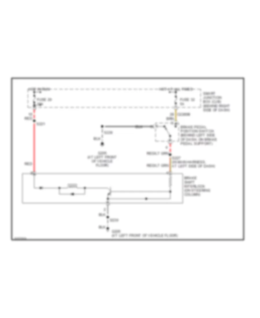 https://portal-diagnostov.com/license.html
Automotive Electricians Portal FZCO
Automotive Electricians Portal FZCO
https://portal-diagnostov.com/license.html
https://portal-diagnostov.com/license.html
Automotive Electricians Portal FZCO
Automotive Electricians Portal FZCOList of elements for Shift Interlock Wiring Diagram for Ford Ranger 2006:
- Brake pedal position switch (behind left side of dash, on brake pedal support)
- Brake shift interlock (on steering column)
- C2280b
- Fuse 20 10a
- Fuse 32 5a
- G205 (at left front of vehicle floor)
- Hot at all times
- Hot in run
- Red
- S221
- S227 (in main harness, at left side of dash)
- S236
- Smart junction box (cjb) (behind right side of dash)
STARTING/CHARGING
Charging Wiring Diagram for Ford Ranger 2006
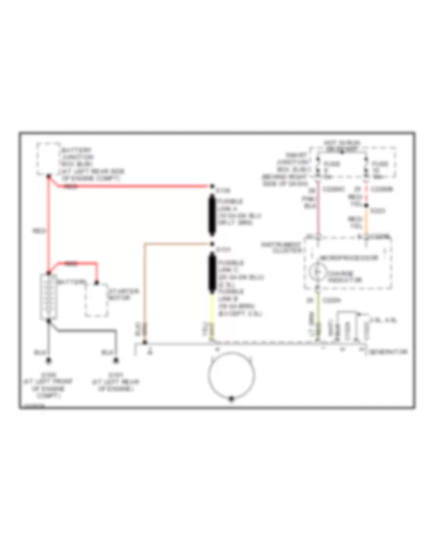 https://portal-diagnostov.com/license.html
Automotive Electricians Portal FZCO
Automotive Electricians Portal FZCO
https://portal-diagnostov.com/license.html
https://portal-diagnostov.com/license.html
Automotive Electricians Portal FZCO
Automotive Electricians Portal FZCOList of elements for Charging Wiring Diagram for Ford Ranger 2006:
- 3.0l, 4.0l
- Battery
- Battery junction box (bjb) (at left rear side of engine compt)
- C102a
- C102c
- C220a
- C220b
- C2280b
- C2280c
- Charge indicator
- Fuse 10a
- Fuse 5a
- G100 (at left front of engine compt)
- G101 (at left rear of engine)
- Generator
- Hot in run or start
- Instrument cluster
- Microprocessor
- Red
- S130
- S131
- S223
- Smart junction box (sjb) (behind right side of dash)
- Starter motor
Starting Wiring Diagram for Ford Ranger 2006
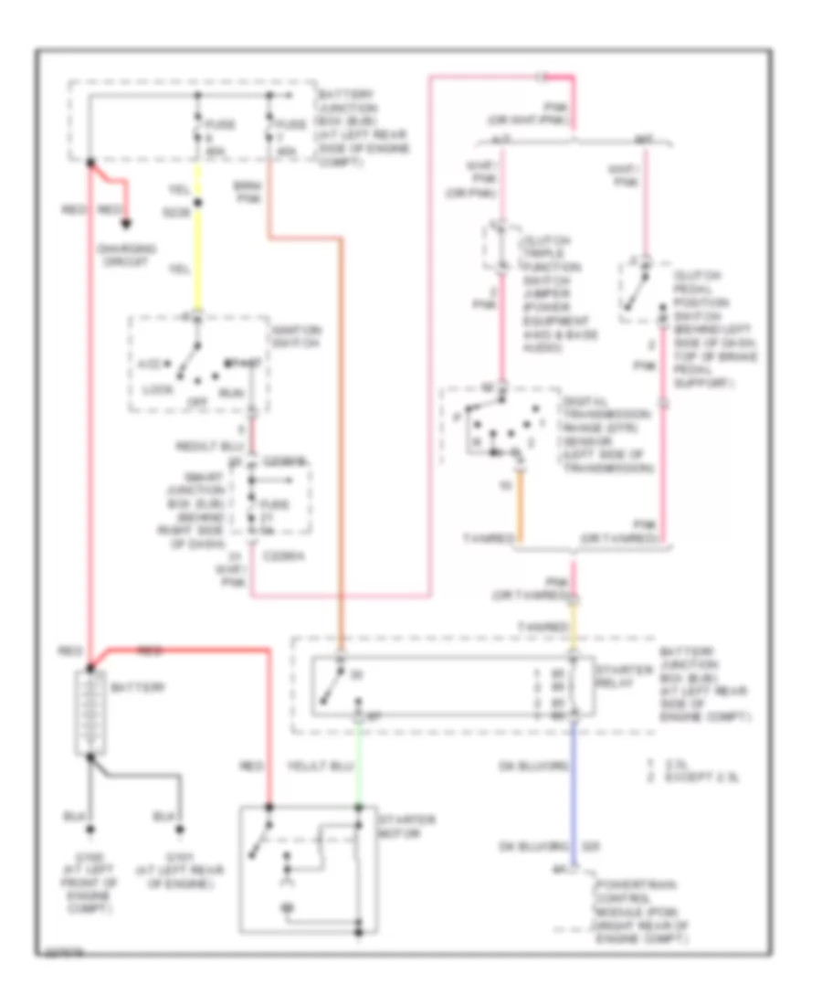 https://portal-diagnostov.com/license.html
Automotive Electricians Portal FZCO
Automotive Electricians Portal FZCO
https://portal-diagnostov.com/license.html
https://portal-diagnostov.com/license.html
Automotive Electricians Portal FZCO
Automotive Electricians Portal FZCOList of elements for Starting Wiring Diagram for Ford Ranger 2006:
- (or pnk)
- 2.3l except 2.3l
- A/t
- Acc
- Battery
- Battery junction box (bjb) (at left rear side of engine compt)
- C2280a
- C2280b
- Charging circuit
- Clutch pedal position switch (behind left side of dash, top of brake pedal support)
- Clutch triple function switch jumper (power equipment 4-wd & base audio)
- Digital transmission range (dtr) sensor (left side of transmission)
- Fuse 40a
- Fuse 5a
- G100 (at left front of engine compt)
- G101 (at left rear of engine)
- Ignition switch
- Lock
- M/t
- Off
- Pnk
- Pnk (or tan/red)
- Powertrain control module (pcm) (right rear of engine compt)
- Red
- Run
- S228
- Smart junction box (sjb) (behind right side of dash)
- Start
- Starter motor
- Starter relay
- Tan/red
SUPPLEMENTAL RESTRAINTS
Supplemental Restraints Wiring Diagram for Ford Ranger 2006
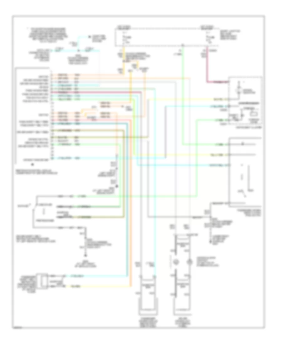 https://portal-diagnostov.com/license.html
Automotive Electricians Portal FZCO
Automotive Electricians Portal FZCO
https://portal-diagnostov.com/license.html
https://portal-diagnostov.com/license.html
Automotive Electricians Portal FZCO
Automotive Electricians Portal FZCOList of elements for Supplemental Restraints Wiring Diagram for Ford Ranger 2006:
- (not used)
- (under front of center console) g204
- Air bag ind ctrl
- Air bag indicator
- Air bag sliding contact (at bottom of steering column)
- Air bag tone driver
- Buckled
- C218b
- C220a
- C220b
- C2280c
- Computer data lines system
- Data link connector (dlc) (at bottom of steering column)
- Dedicated ground
- Driver air bag feed
- Driver air bag return
- Driver air bag unit (in steering wheel)
- Driver safety belt feed
- Driver safety belt retractor pretensioner (at left rear of vehicle floor)
- Driver safety belt rtn
- Except stx
- Fuse 10a
- Fuse 5a
- G204 (at left front of engine compt)
- G205 (at left front of vehicle floor)
- Hot in run or start
- Ignition
- Instrument cluster
- Iso bus
- Microprocessor
- Nca
- Near breakout for center of dash) s201
- Of dash)
- Off
- Pad switch ind ctrl
- Pad switch input
- Pass air bag feed
- Pass air bag return
- Pass safety belt feed
- Pass safety belt rtn
- Passenger air bag deactivation (pad) switch
- Passenger air bag module (behind right side of dash)
- Passenger safety belt retractor pretensioner (at right rear of vehicle floor)
- Pin shorting bars engaged when module connector is disconnected from harness: (shorting bars are connected between following pins: 3-4, 6-7 & 20-21)
- Pretensioner
- Restraints control module (under front of center console)
- S118 (left side of engine compt)
- S206 (in main harness, near breakout for audio unit)
- S208 (in main harness, near breakout for audio unit)
- Safety belt ind
- Shorting bar
- Smart junction box (sjb) (behind right side of dash)
- Stx
- Tone sig
- Unbuckled
- Warning chime
TRANSMISSION
4WD Wiring Diagram for Ford Ranger 2006
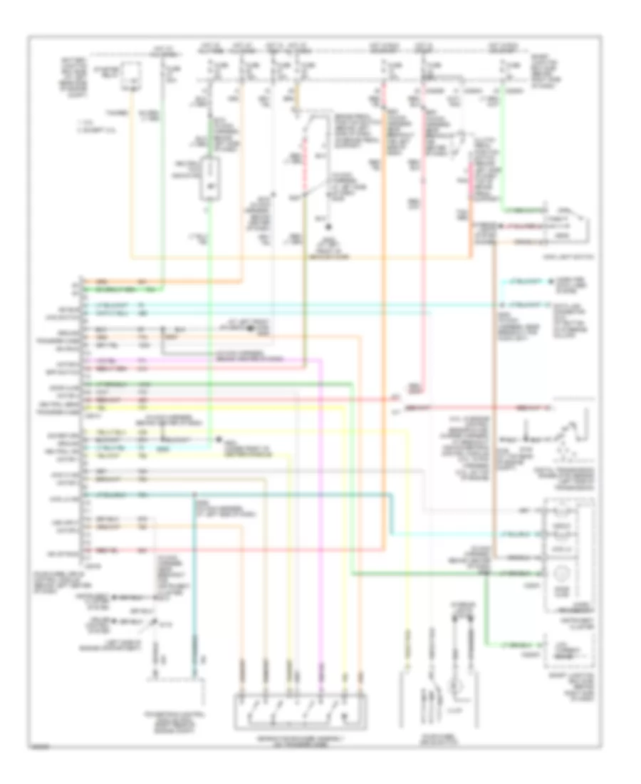 https://portal-diagnostov.com/license.html
Automotive Electricians Portal FZCO
Automotive Electricians Portal FZCO
https://portal-diagnostov.com/license.html
https://portal-diagnostov.com/license.html
Automotive Electricians Portal FZCO
Automotive Electricians Portal FZCOList of elements for 4WD Wiring Diagram for Ford Ranger 2006:
- (2.3l: on top of engine)
- (4.0l: in engine control sensor & fuel charge harness, at breakout for powertrain control module) (3.0l: in pcm harness)
- (at left front of vehicle floor) g205
- (in main harness, at left side of dash) s236
- (in main harness, behind center of dash)
- (in main harness, behind center of dash) s220
- (in main harness, near breakout for instrument cluster) s213
- (left side of engine compartment)
- 2.3l
- 4wd hi
- 4wd hi ind
- 4wd lo
- 4wd lo ind
- 4wd switch
- A/t
- Battery junction box (bjb) (at left rear side of engine compt)
- Bpp switch
- Brake pedal position switch (behind left side of dash, on brake pedal support)
- C220a
- C2280a
- C2280b
- C2280c
- C281a
- C281b
- Clutch pedal position switch (behind left side of dash, top of brake pedal support)
- Computer data lines system
- Cruise control system
- Data link connector (dlc) (at bottom of steering column)
- Digital transmission range (dtr) sensor (left side of transmission)
- Door ajar
- Except 2.3l
- Four-wheel drive control module (behind left center of dash)
- Four-wheel drive switch
- Fuse 10a
- Fuse 15a
- Fuse 20a
- Fuse 5a
- G106 (at top rear of engine compt)
- G204 (under front of center console)
- G205 (at left front of vehicle floor)
- Gearmotor encoder assembly (on transfer case)
- Ground
- Head
- Hot at all times
- Hot in run
- Hot in run or start
- Hot in start
- Ign (run)
- Ign (st/run)
- Illum
- Instrument cluster
- Instrument cluster system
- Interior lights system
- Interior lights system (dimmer)
- Iso bus
- Left side of dash)
- Low current board
- M/t
- Main light switch
- Micro- processor
- Motor 1
- Motor 2
- Motor 3
- Motor 4
- Motor 5
- Neutral ind
- Neutral sens
- Neutral tow indicator
- Off
- Park
- Pnk
- Powertrain control module (pcm) (right rear of engine compt)
- S116
- S145
- S200 (in main harness, near breakout for center of dash)
- S203
- S208 (in main harness, near breakout for audio unit)
- S209
- S216 (in main harness, behind center of dash)
- S223 (in main harness, near breakout for left side of dash)
- S227
- S258 (in main harness, at left side of dash)
- Sig return
- Smart junction box (sjb) (behind right side of dash)
- Starter relay
- Tan/ red
- Tan/red
- Transfer case
- Vss input
2.3L
2.3L, A/T Wiring Diagram (1 of 2) for Ford Ranger 2006
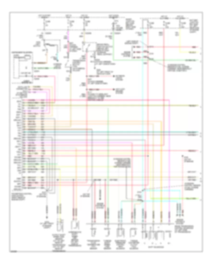 https://portal-diagnostov.com/license.html
Automotive Electricians Portal FZCO
Automotive Electricians Portal FZCO
https://portal-diagnostov.com/license.html
https://portal-diagnostov.com/license.html
Automotive Electricians Portal FZCO
Automotive Electricians Portal FZCOList of elements for 2.3L, A/T Wiring Diagram (1 of 2) for Ford Ranger 2006:
- (left side of engine compt)
- (dlc) (at bottom of steering column)
- (in engine control sensor & fuel charge harness)
- (in engine control sensor & fuel charge harness, near breakout for fuel injector 4)
- (in engine control sensor & fuel charge harness, near breakout for transmission)
- (on top of engine)
- 5r44e transmission control solenoids (at left side of transmission)
- A/t
- Anti-lock brakes system
- Battery junction box (bjb) (at left rear side of engine compt)
- Bpp
- Brake pedal position switch (behind left side of dash, on brake pedal support)
- C220a
- C220b
- C2280a
- C2280b
- C2280c
- Check engine ind
- Cht
- Data link connector
- Electronic pressure control (epc) solenoid
- Engine controls system
- Epc
- Exterior lights system
- Feps
- Fuse 10a
- Fuse 15a
- Fuse 30a
- Fuse 5a
- G104 (at left front of engine compt)
- G205 (at left front of vehicle floor)
- Ground
- Harness, at left side of dash)
- Head
- Hot at all times
- Hot in run
- Hot in run or start
- Hot in start or run
- Instrument cluster
- Interior lights system
- Intermediate shaft speed (iss) sensor (on left side of transmission)
- Iss
- Junction harness, near breakout to abs control module)
- M/t
- Main light switch
- Micro-
- Mil
- Nca
- O/d off ind
- Off
- Oss
- Output shaft speed (oss) sensor (a/t: on left rear of transmission) (m/t: at left rear of transmission)
- Park
- Pcm power diode
- Power
- Powertrain control module (pcm) (right rear of engine compt)
- Prndl
- Processor
- Ptc 1a
- Red
- S107 (on top of engine)
- S113
- S143
- S148
- S149
- S150 (on top of engine)
- S153
- S154
- S236 (in main harness, at left side of dash)
- Scp +
- Scp -
- Shift solenoids
- Sig rtn
- Smart junction box (sjb) (behind right side of dash)
- Ss a
- Ss b
- Ss c
- Ss d
- Tcc
- Tcil
- Tcs
- Tft
- Torque converter clutch (tcc) solenoid
- Tr1
- Tr2
- Tr3a
- Tr4
- Transmission control switch (tcs) (on steering column)
- Transmission fluid temperature (tft) sensor
- Tss
- Turbine shaft speed (tss) sensor
- Vbatt
- Vref
2.3L, A/T Wiring Diagram (2 of 2) for Ford Ranger 2006
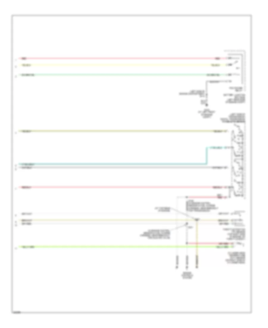 https://portal-diagnostov.com/license.html
Automotive Electricians Portal FZCO
Automotive Electricians Portal FZCO
https://portal-diagnostov.com/license.html
https://portal-diagnostov.com/license.html
Automotive Electricians Portal FZCO
Automotive Electricians Portal FZCOList of elements for 2.3L, A/T Wiring Diagram (2 of 2) for Ford Ranger 2006:
- (at top rear of engine)
- (in engine control sensor & fuel charge harness, near breakout for idle air valve)
- (left side of engine compartment) s118
- (left side of transmission) digital transmission range (dtr) sensor
- Battery junction box (bjb) (left rear side of engine compt)
- Cylinder head temperature (cht) sensor (on right side of cylinder head)
- Engine controls system
- G104 (at left front of engine compt)
- Pcm power relay
- R p
- Red
- S137
- S151
- S152 (in engine control sensor & fuel charge harness, near breakout for transmission)
- Throttle position (tp) sensor (top right side of engine, on throttle body)
3.0L
3.0L, A/T Wiring Diagram (1 of 2) for Ford Ranger 2006
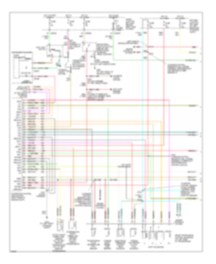 https://portal-diagnostov.com/license.html
Automotive Electricians Portal FZCO
Automotive Electricians Portal FZCO
https://portal-diagnostov.com/license.html
https://portal-diagnostov.com/license.html
Automotive Electricians Portal FZCO
Automotive Electricians Portal FZCOList of elements for 3.0L, A/T Wiring Diagram (1 of 2) for Ford Ranger 2006:
- (dlc) (at bottom of steering column)
- (in engine control sensor & fuel charge harness, at breakout for powertrain control module)
- (in engine control sensor & fuel charge harness, near breakout for camshaft position sensor)
- (in engine control sensor & fuel charge harness, near breakout for heated oxygen sensor 21)
- (left side of engine compartment)
- (on top of transmission)
- 5r44e transmission control solenoids (at left side of transmission)
- Anti-lock brakes system
- Battery junction box (bjb) (at left rear side of engine compt)
- Bpp
- Brake pedal position switch (behind left side of dash, on brake pedal support)
- C220a
- C220b
- C2280a
- C2280b
- C2280c
- Check engine ind
- Data link connector
- Ect
- Electronic pressure control (epc) solenoid
- Engine controls system
- Epc
- Exterior lights system
- Feps
- Fuse 10a
- Fuse 15a
- Fuse 30a
- Fuse 5a
- G104 (at left front of engine compt)
- G205 (at left front of vehicle floor)
- Ground
- Harness, at left side of dash)
- Head
- Hot at all times
- Hot in run
- Hot in run or start
- Hot in start or run
- Instrument cluster
- Interior lights system
- Intermediate shaft speed (iss) sensor (on left side of transmission)
- Iss
- Junction harness, near breakout to abs control module)
- M/t a/t
- Main light switch
- Micro-
- Mil
- Nca
- O/d off ind
- Off
- Oss
- Output shaft speed (oss) sensor (a/t: on left rear of transmission) (m/t: at left rear of transmission)
- Park
- Pcm power diode
- Power
- Powertrain control module (pcm) (right rear of engine compt)
- Prndl
- Processor
- Ptc 1a
- Red
- S100
- S104
- S106
- S107 (in pcm harness)
- S113
- S129 (in engine control sensor & fuel charge harness, at breakout for powertrain control module)
- S143
- S236 (main harness,
- Scp +
- Scp -
- Shift solenoids
- Sig rtn
- Smart junction box (sjb) (behind right side of dash)
- Ss a
- Ss b
- Ss c
- Ss d
- Tcc
- Tcil
- Tcs
- Tft
- Torque converter clutch (tcc) solenoid
- Tr1
- Tr2
- Tr3a
- Tr4
- Transmission control switch (tcs) (on steering column)
- Transmission fluid temperature (tft) sensor
- Tss
- Turbine shaft speed (tss) sensor
- Vbatt
- Vref
3.0L, A/T Wiring Diagram (2 of 2) for Ford Ranger 2006
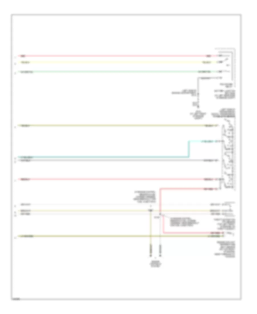 https://portal-diagnostov.com/license.html
Automotive Electricians Portal FZCO
Automotive Electricians Portal FZCO
https://portal-diagnostov.com/license.html
https://portal-diagnostov.com/license.html
Automotive Electricians Portal FZCO
Automotive Electricians Portal FZCOList of elements for 3.0L, A/T Wiring Diagram (2 of 2) for Ford Ranger 2006:
- (in engine control sensor & fuel charge harness, near breakout for fuel injector 5)
- (in engine control sensor & fuel charge harness, near breakout for fuel injector 6)
- (left side of engine compartment) s118
- (left side of transmission) digital transmission range (dtr) sensor
- Battery junction box (bjb) (at left rear side of engine compt)
- Engine controls system
- Engine coolant temperature (ect) sensor (on top front of engine, near thermostat housing)
- G104 (at left front of engine compt)
- Pcm power relay
- R p
- Red
- S137
- S139
- Throttle position (tp) sensor (top left front of engine, on throttle body)
4.0L
4.0L, A/T Wiring Diagram (1 of 2) for Ford Ranger 2006
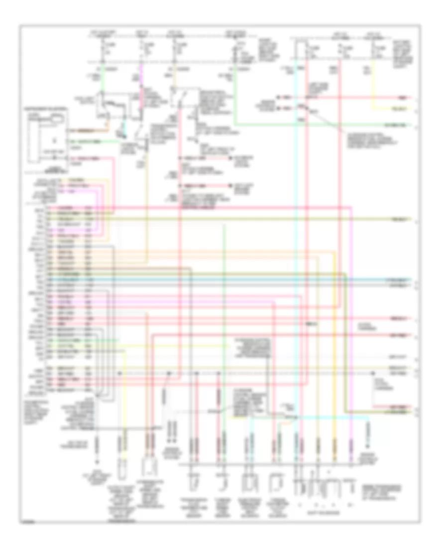 https://portal-diagnostov.com/license.html
Automotive Electricians Portal FZCO
Automotive Electricians Portal FZCO
https://portal-diagnostov.com/license.html
https://portal-diagnostov.com/license.html
Automotive Electricians Portal FZCO
Automotive Electricians Portal FZCOList of elements for 4.0L, A/T Wiring Diagram (1 of 2) for Ford Ranger 2006:
- (dlc) (at bottom of steering column)
- (in engine control sensor & fuel charge harness, near breakout for ignition coil)
- (in engine control sensor & fuel charge harness, near breakout for transmission)
- (in engine control sensor & fuel charge harness, near breakout to heated oxygen sensor 11)
- (in pcm harness)
- (left side of engine compt) s113
- (on top of transmission)
- 5r55e transmission control solenoids (at left side of transmission)
- Anti-lock brakes system
- Battery junction box (bjb) (at left rear side of engine compt)
- Bpp
- Brake pedal position switch (behind left side of dash, on brake pedal support)
- C220a
- C220b
- C2280a
- C2280b
- C2280c
- Check engine ind
- Data link connector
- Dlc
- Dlc (+)
- Dlc (-)
- Ect
- Electronic pressure control (epc) solenoid
- Engine controls system
- Epc
- Exterior lights system
- Fuse 10a
- Fuse 15a
- Fuse 30a
- Fuse 5a
- G104 (at left front of engine compt)
- G205 (at left front of vehicle floor)
- Ground
- Harness, at left side of dash)
- Head
- Hot at all times
- Hot in run
- Hot in run or start
- Hot in start or run
- Instrument cluster
- Interior lights system
- Intermediate shaft speed (iss) sensor (on left rear of transmission)
- Iss
- Junction harness, near breakout to abs control module)
- Main light switch
- Micro-
- Mil
- Nca
- O/d off ind
- Off
- Oss
- Output shaft speed (oss) sensor (a/t: on left rear of transmission) (m/t: at left rear of transmission)
- Park
- Pcm power diode
- Power
- Powertrain control module (pcm) (right rear of engine compt)
- Prndl
- Processor
- Ptc 1a
- Red
- S104
- S107 (in engine control sensor & fuel charge harness, at breakout for powertrain control module)
- S129
- S140
- S141
- S143 (in pcm harness)
- S144
- S236 (in main harness, at left side of dash)
- Shift solenoids
- Sig rtn
- Smart junction box (sjb) (behind right side of dash)
- Ss a
- Ss b
- Ss c
- Ss d
- Tcc
- Tcil
- Tcs
- Tft
- Torque converter clutch (tcc) solenoid
- Tr1
- Tr2
- Tr3a
- Tr4
- Transmission control switch (tcs) (on steering column)
- Transmission fluid temperature (tft) sensor
- Tss
- Turbine shaft speed (tss) sensor
- Vbatt
- Vref
4.0L, A/T Wiring Diagram (2 of 2) for Ford Ranger 2006
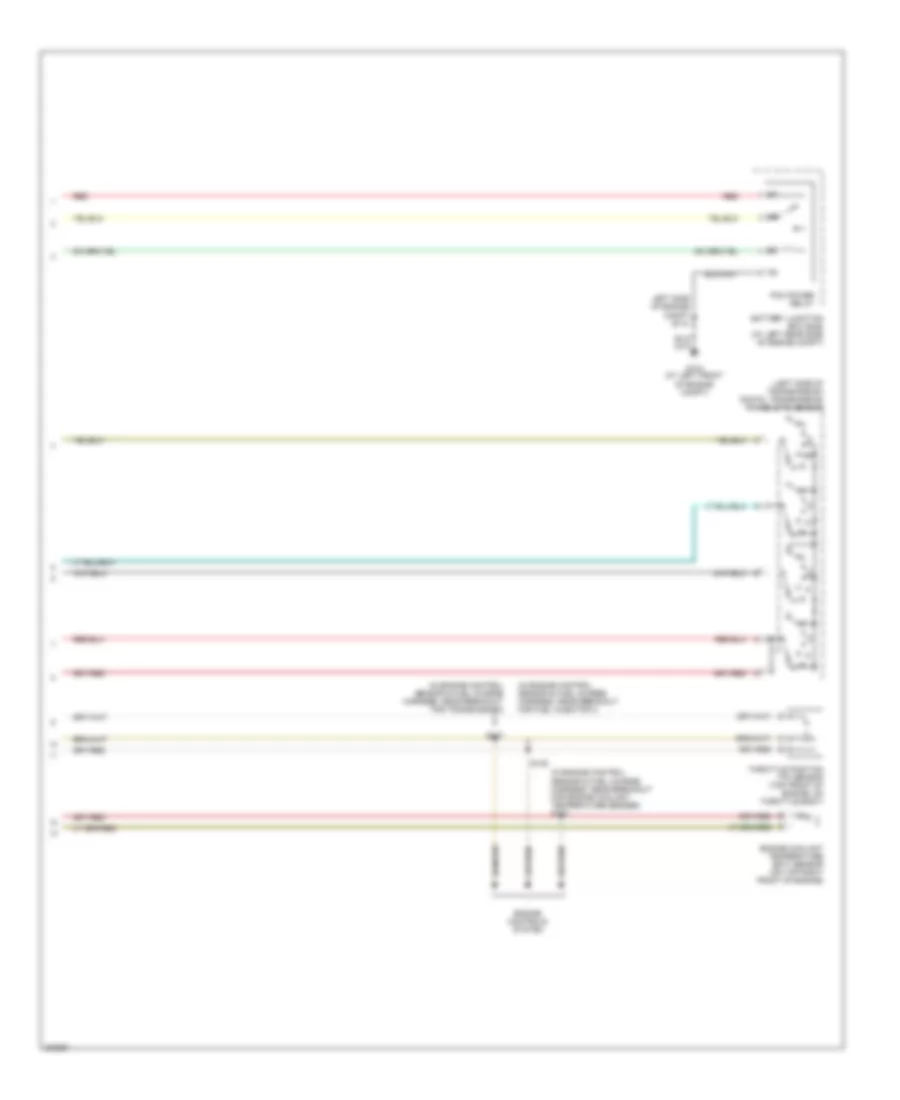 https://portal-diagnostov.com/license.html
Automotive Electricians Portal FZCO
Automotive Electricians Portal FZCO
https://portal-diagnostov.com/license.html
https://portal-diagnostov.com/license.html
Automotive Electricians Portal FZCO
Automotive Electricians Portal FZCOList of elements for 4.0L, A/T Wiring Diagram (2 of 2) for Ford Ranger 2006:
- (in engine control sensor & fuel charge harness, near breakout for engine coolant temperature sender) s133
- (in engine control sensor & fuel charge harness, near breakout for fuel injector 4)
- (in engine control sensor & fuel charge harness, near breakout for transmission)
- (left side of transmission) digital transmission range (dtr) sensor
- Battery junction box (bjb) (at left rear side of engine compt)
- Engine controls system
- Engine coolant temperature (ect) sensor (on top right front of engine)
- G104 (at left front of engine compt)
- Left side of engine compt s118
- Pcm power relay
- R p
- Red
- S135
- S137
- Throttle position (tp) sensor (top front of engine, on throttle body)
WARNING SYSTEMS
Warning Systems Wiring Diagram for Ford Ranger 2006
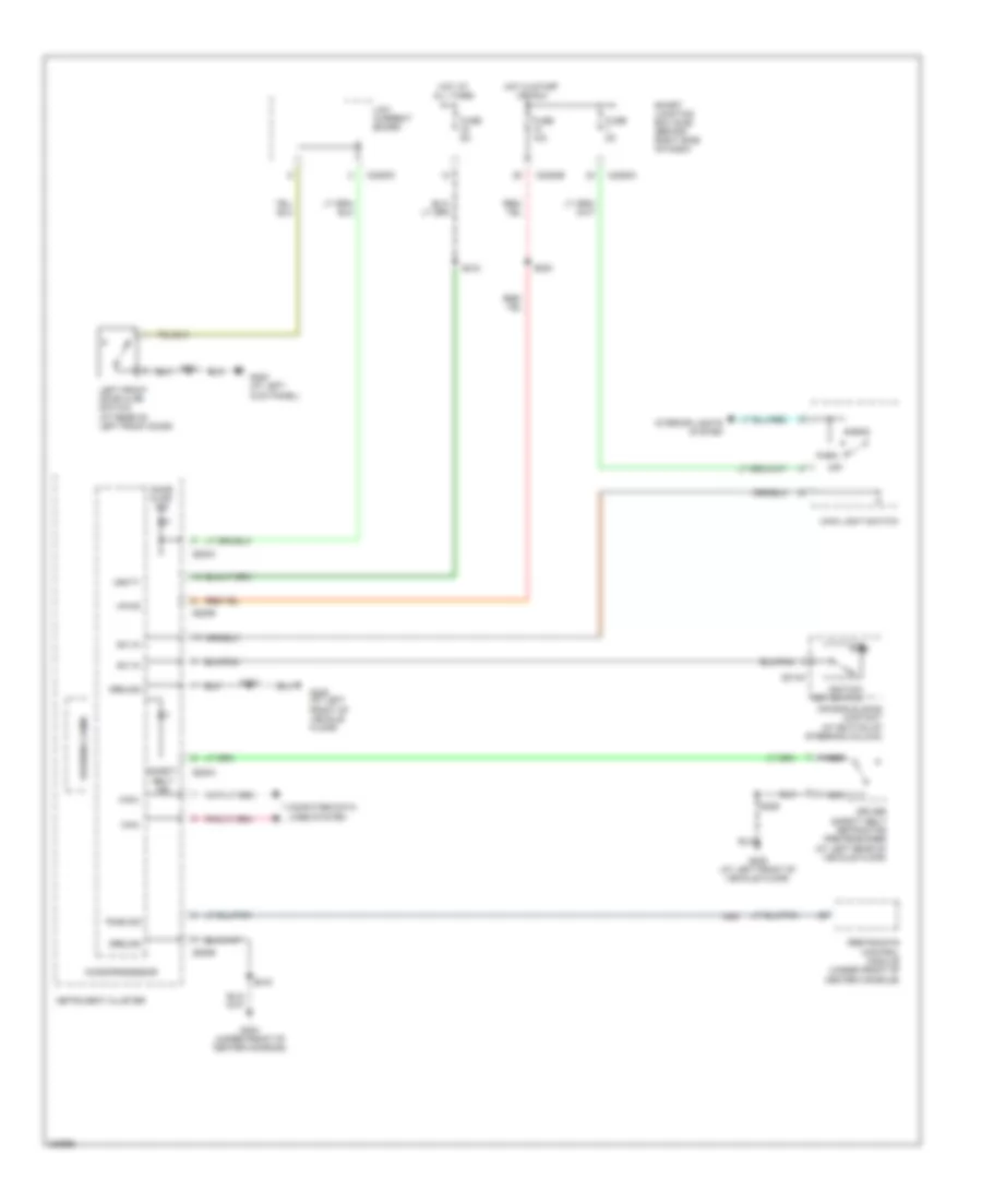 https://portal-diagnostov.com/license.html
Automotive Electricians Portal FZCO
Automotive Electricians Portal FZCO
https://portal-diagnostov.com/license.html
https://portal-diagnostov.com/license.html
Automotive Electricians Portal FZCO
Automotive Electricians Portal FZCOList of elements for Warning Systems Wiring Diagram for Ford Ranger 2006:
- Air bag sliding contact (at bottom of steering column)
- C218a
- C220a
- C220b
- C2280b
- C2280c
- Can+
- Can-
- Computer data lines system
- Door ajar ind
- Driver safety belt retractor pretensioner (at left rear of vehicle floor)
- Fuse 10a
- Fuse 5a
- G200 (at left kick panel)
- G204 (under front of center console)
- G205 (at left front of vehicle floor)
- Ground
- Head
- Hot at all times
- Hot in start or run
- Ignition key switch
- Instrument cluster
- Interior lights system
- Left front door ajar switch (at rear of left front door)
- Low current board
- Main light switch
- Microprocessor
- Nca
- Off
- Park
- Restraints control module (under front of center console)
- S203
- S206
- S215
- S218
- S223
- S501
- Safety belt ind
- Smart junction box (sjb) (behind right side of dash)
- Sw in
- Tone sig
- Vbatt
- Vpwr
- Warning chime
WIPER/WASHER
Wiper/Washer Wiring Diagram for Ford Ranger 2006
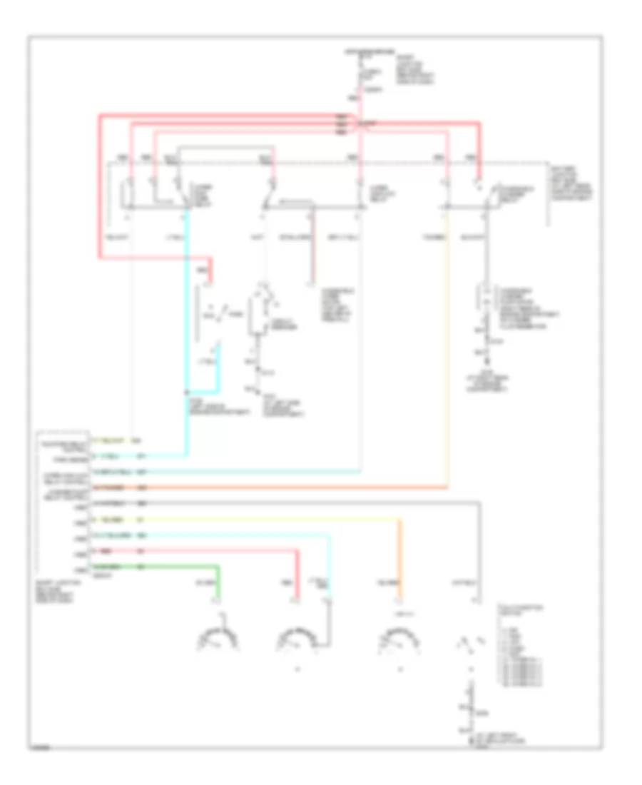 https://portal-diagnostov.com/license.html
Automotive Electricians Portal FZCO
Automotive Electricians Portal FZCO
https://portal-diagnostov.com/license.html
https://portal-diagnostov.com/license.html
Automotive Electricians Portal FZCO
Automotive Electricians Portal FZCOList of elements for Wiper/Washer Wiring Diagram for Ford Ranger 2006:
- (at left front of vehicle floor) g205
- 0. off 1. high 2. low 6. wash 7. mist 21. interval 1 22. interval 2 23. interval 3 24. interval 4 25. interval 5
- Battery junction box (bjb) (at left rear side of engine compartment)
- C2280a
- Circuit breaker
- Fuse 5 30a
- G103 (at left side of engine compartment)
- G105 (at right rear of engine compartment)
- Hot in run or acc
- Multi-function switch
- Park
- Park sense
- Red
- Run
- Run/park relay control
- S109 (left side of engine compartment)
- S110
- S123
- S127
- S236
- Smart junction box (sjb) (behind right side of dash)
- Tan/red
- Vref
- Washer pump relay control
- Windshield washer pump motor (right rear of engine compartment, on washer fluid reservoir)
- Windshield washer relay
- Windshield wiper motor (top left center of firewall)
- Wiper high/low relay
- Wiper high/low relay control
- Wiper run/ park relay

 Čeština
 Dansk
Dansk Deutsch
 Ελληνικά
 English
 English
 Español
 Suomi
Suomi Français
 Français
 עברית
עברית Hrvatski
 Magyar
 Italiano
 日本語
日本語 한국어
한국어 Nederlands
 Polski
 Português
 Português
 Română
 Русский
 Slovenčina
 Slovenščina
 Svenska
 中文 (中国)
