AIR CONDITIONING
A/C Wiring Diagram for Ford Ranger Splash 1997
 https://portal-diagnostov.com/license.html
Automotive Electricians Portal FZCO
Automotive Electricians Portal FZCO
https://portal-diagnostov.com/license.html
https://portal-diagnostov.com/license.html
Automotive Electricians Portal FZCO
Automotive Electricians Portal FZCO
List of elements for A/C Wiring Diagram for Ford Ranger Splash 1997:
- (alternator rectifier system harness, left front of engine)
- (dash panel to headlamp junction in blower motor breakout) s114
- (top center of left fender apron)
- A/c clutch cycling pressure switch (right rear of engine compartment, on accumulator)
- A/c clutch diode
- A/c clutch field coil
- A/c pressure cutoff switch (left front of engine on a/c line)
- A/c-heater control assembly
- Blend door actuator (behind right side of i/p)
- Blower motor
- Blower motor fuse 40a
- Blower motor relay (in relay box 2)
- Blower motor resistor assembly (right rear of engine comparment)
- Blower switch
- C231
- C233
- C234
- Def
- Engine compartment fuse/relay box
- Flr
- Flr/def
- Fuse 15a
- Fuse 7.5a
- G102
- G102 (top center of left fender apron)
- Hot at all times
- Hot in run
- I/p fuse panel
- Illumi- nation
- Interior lights system
- Max
- Norm
- Off
- Pan/flr
- Panel
- Pcm power relay
- Powertrain control module (pcm) (right rear of engine compartment, through safety wall)
- Red
- S115 (dash panel to headlamp junction harn, near relay box 2 breakout)
- S137 (dash panel to headlamp junction harn, left rear of engine compt)
- S145
- S146 (alternator rectifier system harness, left front of engine)
- S209 (main harness, behind center of i/p)
- S212 (main harness, behind center of i/p)
- S227 (main harness, near instrument cluster breakout)
- S250 (main harn, near fuse panel breakout)
- Wide open throttle a/c cutoff relay (in engine compartment fuse/relay box)
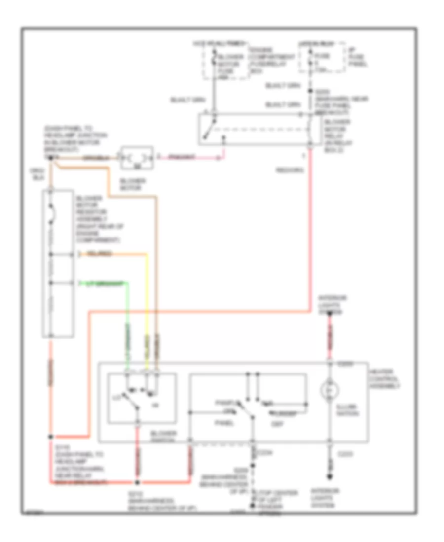
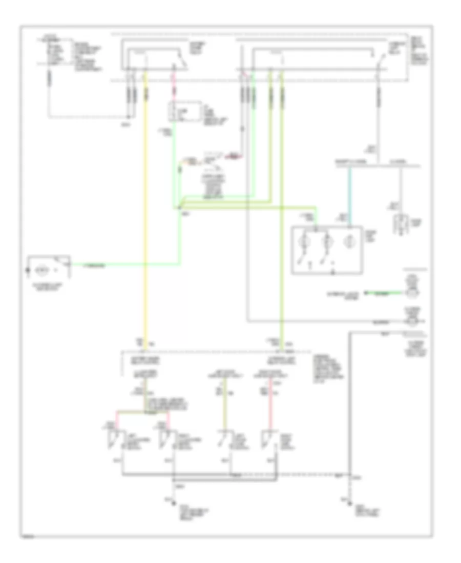
Heater Wiring Diagram for Ford Ranger Splash 1997
 https://portal-diagnostov.com/license.html
Automotive Electricians Portal FZCO
Automotive Electricians Portal FZCO
https://portal-diagnostov.com/license.html
https://portal-diagnostov.com/license.html
Automotive Electricians Portal FZCO
Automotive Electricians Portal FZCOList of elements for Heater Wiring Diagram for Ford Ranger Splash 1997:
- (dash panel to headlamp junction in blower motor breakout) s114
- (top center of left fender apron)
- Blower motor
- Blower motor fuse 40a
- Blower motor relay (in relay box 2)
- Blower motor resistor assembly (right rear of engine comparment)
- Blower switch
- C233
- Def
- Engine compartment fuse/relay box
- Flr
- Flr/def
- Fuse 7.5a
- G102
- Heater control assembly
- Hot at all times
- Hot in run
- I/p fuse panel
- Illumi- nation
- Interior lights system
- Off
- Pan/flr
- Panel
- S115 (dash panel to headlamp junction harn, near relay box 2 breakout)
- S212 (main harness, behind center of i/p)
- S250 (main harn, near fuse panel breakout)
ANTI-LOCK BRAKES
All-Wheel ABS Wiring Diagram for Ford Ranger Splash 1997
 https://portal-diagnostov.com/license.html
Automotive Electricians Portal FZCO
Automotive Electricians Portal FZCO
https://portal-diagnostov.com/license.html
https://portal-diagnostov.com/license.html
Automotive Electricians Portal FZCO
Automotive Electricians Portal FZCOList of elements for All-Wheel ABS Wiring Diagram for Ford Ranger Splash 1997:
- (4wabs) hydraulic unit (left side of engine compartment)
- (4wabs) indicator ctrl
- (4wabs) main relay (relay box #3: left rear of engine compt.)
- (4wabs) pmp rly coil (-) g-switch #2
- (4wabs) pump motor relay (relay box #3)
- (4wabs) relay coil (-)
- (dash to headlamp harn, in breakout to relay box 3) s129
- (left front of vehicle)
- 1400 ohms
- 4wabs diode
- 4wabs main relay maxi fuse 9 30a
- 4wabs pump motor
- 4wabs pump relay maxi fuse 10 30a
- Acceleration sensor (on inside of left frame rail)
- Anti-lock brakes indicator
- Brake on/off (boo) switch (on brake pedal support)
- Brake on/off sw feed
- C215
- C216
- Connector (dlc) (bottom of i/p, near steering column)
- Data link
- Diagnostic circuit
- Dump valve
- Engine compartment fuse/relay box (left rear of engine compt.)
- Four wheel anti- lock brake system (4wabs) control module (left front of engine compartment)
- Fuse 10a
- Fuse 15a
- Fuse 7.5a
- G-switch #1
- G-switch status
- G104 (top center of left fender apron)
- G108 (left side of upper radiator support)
- Ground
- Hot at all times
- Hot in run
- Hot in run or start
- I/p fuse panel (behind left side of i/p)
- Ignition (hot in run)
- Instrument cluster
- Iso
- Iso valve
- Left front
- Left front dump valve
- Left front iso valve
- Left front sensor (hi)
- Left front sensor (lo)
- Left front wheel speed sensor
- Motor speed sensor (hi)
- Nca
- Pnk
- Rear
- Rear axle sensor
- Rear dump valve
- Rear iso valve
- Rear sensor (high)
- Rear sensor (low)
- Red/pnk
- Right front
- Right front dump valve
- Right front iso valve
- Right front sensor (hi)
- Right front sensor (lo)
- Right front wheel speed sensor
- S118
- S124
- S125
- S132 (dash to headlamp harn, near breakout to starter relay)
- S142
- S148
- S225
- S240
- Tan
- Tan/red
- Valve
- Vehicle ref. voltage
Rear Wheel ABS Wiring Diagram for Ford Ranger Splash 1997
 https://portal-diagnostov.com/license.html
Automotive Electricians Portal FZCO
Automotive Electricians Portal FZCO
https://portal-diagnostov.com/license.html
https://portal-diagnostov.com/license.html
Automotive Electricians Portal FZCO
Automotive Electricians Portal FZCOList of elements for Rear Wheel ABS Wiring Diagram for Ford Ranger Splash 1997:
- (main harn, near breakout to i/p fuse panel) s235
- (main harn, near breakout to i/p fuse panel) s236
- 1.2 ohms
- 22k ohms
- 4.0 ohms
- Abs ind
- Acc
- Boo switch input
- Brake fluid level sig
- Brake fluid level switch (left rear of engine compartment, on brake fluid reservoir)
- Brake ind
- Brake on/off (boo) switch (behind left side of i/p, on brake pedal support)
- C141
- C215
- C216
- Daytime running lamps (drl) module (left side of lower radiator support)
- Diag/keep alive input
- Diff speed sens (hi)
- Diff speed sens (lo)
- Dump sol output
- Engine compartment fuse/relay box (left rear of engine compt.)
- Fuse 11 7.5a
- Fuse 13 15a
- Fuse 14 20a
- Fuse 9 10a
- G104 (top center of left fender apron)
- G108 (left side of upper radiator support)
- Gnd
- Ground
- Hot at all times
- Hot in run
- Hot in run or start
- I/p fuse panel (behind left side of i/p)
- Ignition switch
- Instrument cluster
- Iso sol output
- Isolation solenoid
- Lock
- Nca
- Off
- Power input
- Rabs diode
- Rabs ind ctrl
- Rabs resistor
- Rabs test connector (c244) (behind right side of i/p)
- Rabs test connector (on rear of engine compartment fuse/relay box)
- Rear anti-lock brake system (rabs) module (behind lower center of i/p, left side of ashtray assembly)
- Rear anti-lock brake system (rabs) proportioning valve switch assembly (below left side of vehicle, on inside of left frame rail)
- Rear axle sensor (top of rear differential)
- Red
- Red/pnk
- Run
- S118
- S120 (dash to headlamp harn, left side of safety wall)
- S131
- S150 (dash to headlamp harn, in breakout to engine cpmpt fuse/relay box)
- S204
- S205
- S228
- S240
- S244
- Start
- Valve reset input
- Valve reset switch
ANTI-THEFT
Anti-theft Wiring Diagram for Ford Ranger Splash 1997
 https://portal-diagnostov.com/license.html
Automotive Electricians Portal FZCO
Automotive Electricians Portal FZCO
https://portal-diagnostov.com/license.html
https://portal-diagnostov.com/license.html
Automotive Electricians Portal FZCO
Automotive Electricians Portal FZCOList of elements for Anti-theft Wiring Diagram for Ford Ranger Splash 1997:
- (closed when door is unlocked w/ key)
- (dlc) in
- (int lamp harn, behind left cowl panel)
- (main harn, near fuse panel)
- All lock relay
- All unlock relay
- Anti-theft hood switch
- C214
- C219
- C222
- C409
- C410
- Clock spring assembly (top of steering column)
- Cruise control system
- Data link connector (dlc) (fastened to bottom of i/p, near steering column)
- Door ajar
- Door ajar in
- Door disarm in
- Driver's unlock relay (right side of i/p)
- Engine compartment fuse/relay box (left rear of engine compt.)
- Exterior lights system
- Fuel sys/ anti-theft maxi fuse 3 20a
- Fuse 10a
- Fuse 7.5a
- G104 (top center of left fender apron)
- G105 (right side of engine compartment, on upper fender apron)
- G108 (left side of upper radiator support)
- G200 (behind left cowl panel)
- Generic electronic module (gem)/ central timer module (ctm) (behind center of i/p)
- Ground
- Hood sw in
- Horn rly out
- Horns system
- Hot at all times
- Hot in acc or run
- Hot in start
- I/p fuse panel (left side of i/p)
- Ign tamper sw in
- Ignition tamper switch
- Illum entry
- Illum entry ctrl
- Instrument cluster
- Left door disarm switch
- Left door lock motor
- Left door lock switch
- Lock
- Lock in/out
- Nca
- Park lp rly ctrl
- Power lock/ window/seat maxi fuse 5 20a
- Pwr (bat)
- Pwr (ign)
- Relay box #1 (behind i/p, right of steering column)
- Remote anti-theft personality (rap) module (left rear corner of cab)
- Right door disarm switch (closed when door is unlocked w/ key)
- Right door lock motor
- Right door lock switch
- S117
- S205
- S214
- S220 (main harn, bottom of column)
- S222
- S223 (main harn, bottom of column)
- S225 (i/p harn, behind center of i/p)
- S233
- S238
- S241
- S302
- S303
- S304
- S306 (int lamp harn, left side of i/p)
- S500
- S600
- Start rly ctrl
- Starter interrupt relay (in relay box #1, behind i/p right of steering column)
- Starting/ charging system
- Theft indicator
- Unlock
- Unlock drv's dr
- Unlock in/out
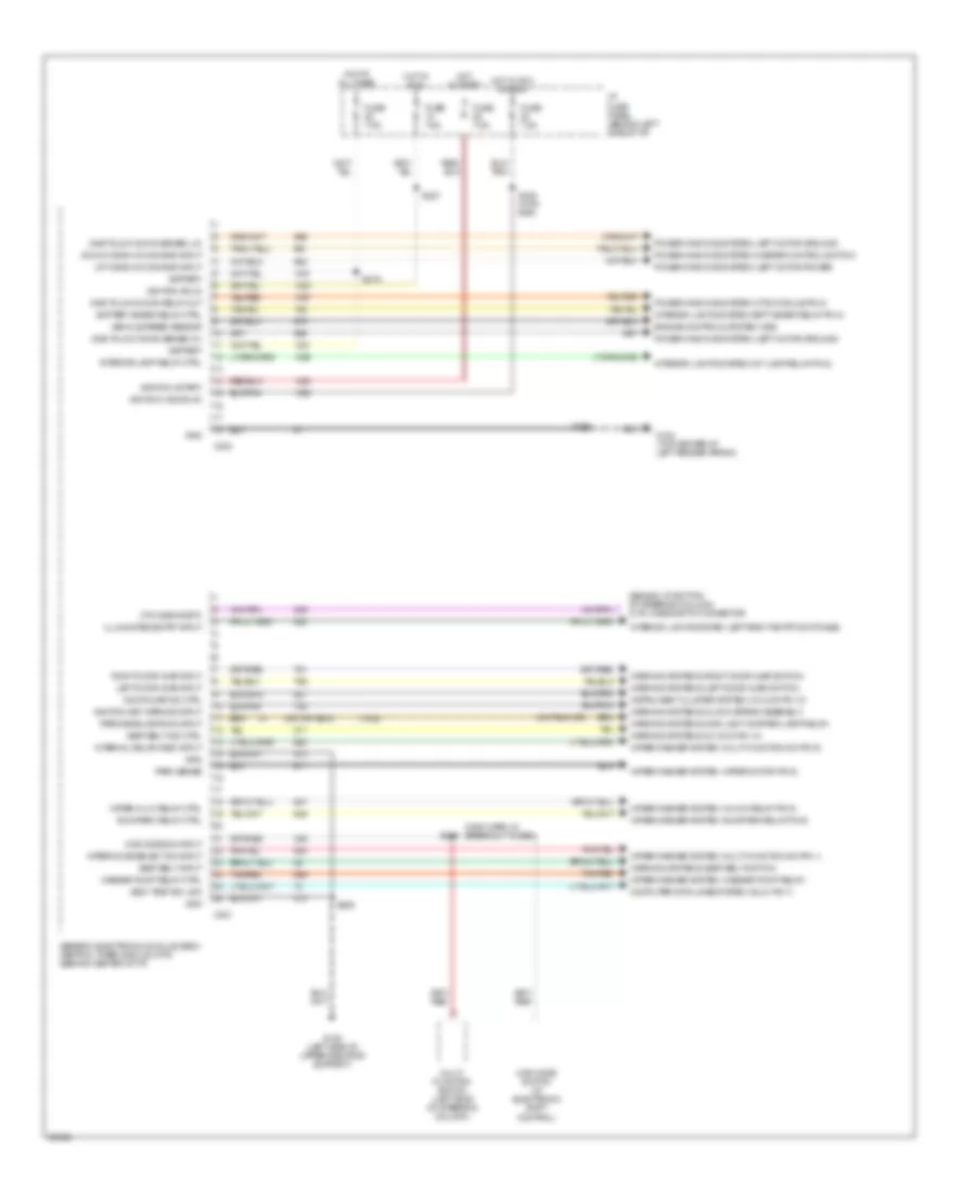
BODY COMPUTER
Body Computer Wiring Diagrams (1 of 2) for Ford Ranger Splash 1997
 https://portal-diagnostov.com/license.html
Automotive Electricians Portal FZCO
Automotive Electricians Portal FZCO
https://portal-diagnostov.com/license.html
https://portal-diagnostov.com/license.html
Automotive Electricians Portal FZCO
Automotive Electricians Portal FZCOList of elements for Body Computer Wiring Diagrams (1 of 2) for Ford Ranger Splash 1997:
- (1032)
- (behind i/p, bottom of steering column) (ctm) diagnostic connector
- (main harn, in breakout to gem)
- 4wd mode sw input
- 4wd mode switch (w/ electronic shift control)
- Battery
- Battery saver relay ctrl
- C221
- C224
- Computer data lines system ((dlc) pin 7)
- Ctm diagnostic
- Door ajar ind ctrl
- Down window command input
- Engine controls system (vss)
- Fuse 7.5a
- G104 (top center of left fender apron)
- G108 (left side of upper radiator support)
- Generic electronic module (gem)/ central timer module (ctm) (behind center of i/p)
- Gnd
- Hot at all times
- Hot in acc or run
- Hot in run
- Hot in start
- I/p fuse panel (behind left side of i/p)
- Ignition (acc/run)
- Ignition (run)
- Ignition (start)
- Ignition key warning input
- Illuminated entry input
- Instrument cluster system (i/c c215 pin 10)
- Interior lamp relay ctrl
- Interior lights system (batt saver relay pin 2)
- Interior lights system (int lamp relay pin 2)
- Interior lights system (left/right entry switches)
- Interval delay/wash input
- Left door ajar input
- Multi- function switch (left side of steering column)
- One touch down relay out
- One touch down sense (hi)
- One touch down sense (lo)
- Park sense
- Park/headlamps on input
- Power windows system (left motor ground)
- Power windows system (left motor power)
- Power windows system (master control switch)
- Power windows system (otd module pin 2)
- Right door ajar input
- Run/park relay ctrl
- S205
- S209
- S215
- S219
- S227
- S238 (with rap)
- Seat belt ind ctrl
- Seat belt input
- Self test iso link
- Tan/red
- Up window command input
- Vehicle speed sensor
- Warning systems (clock spring assembly)
- Warning systems (i/c c216 pin 10)
- Warning systems (left door ajar switch)
- Warning systems (main light sw/park lamp relay)
- Warning systems (right door ajar switch)
- Warning systems (seat belt switch)
- Washer pump relay ctrl
- Wiper hi-lo relay ctrl
- Wiper mode select sw input
- Wiper/washer system (hi/low relay pin 5)
- Wiper/washer system (multi-function sw pin 1)
- Wiper/washer system (multi-function sw pin 6)
- Wiper/washer system (run/park relay pin 5)
- Wiper/washer system (washer pump relay)
- Wiper/washer system (wiper motor pin 6)
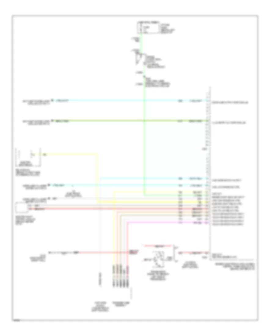
Body Computer Wiring Diagrams (2 of 2) for Ford Ranger Splash 1997
 https://portal-diagnostov.com/license.html
Automotive Electricians Portal FZCO
Automotive Electricians Portal FZCO
https://portal-diagnostov.com/license.html
https://portal-diagnostov.com/license.html
Automotive Electricians Portal FZCO
Automotive Electricians Portal FZCOList of elements for Body Computer Wiring Diagrams (2 of 2) for Ford Ranger Splash 1997:
- 4wd high range ind ctrl
- 4wd low range ind ctrl
- 4wd mode switch (w/ electronic shift control)
- 4wd mode switch output
- 4wd out
- A/t
- Anti-theft system ((rap) module c409 pin 10)
- Anti-theft system ((rap) module c410 pin 11)
- Brake on/off (boo) sw input
- Brake on/off (boo) switch (on brake pedal support)
- C222
- C223
- Door ajar output (rap module)
- Electric shift control module (behind center of i/p)
- Electric shift relay
- Electric shift relay ctrl
- Fuse 15a
- G123 (right side of safety wall)
- Generic electronic module (gem)/ central timer module (ctm) (behind center of i/p)
- Gnd (m/t) neutral sense in (a/t)
- High to low relay ctrl
- Hot at all times
- I/p fuse panel (behind left side of i/p)
- Illum entry out (rap module)
- Instrument cluster system (c214 pin 2)
- Instrument cluster system (c214 pin 3)
- Low to high relay ctrl
- M/t
- Nca
- Relay box #1 (behind i/p, right side of steering column)
- S107
- S228 (main harn, near breakout to generic electronic module)
- Touch drive switch a input
- Touch drive switch b input
- Touch drive switch c input
- Touch drive switch d input
- Transfer case assembly
- Transmission range (tr) sensor (left side of transmission)
- W/ 4wd & electronic shift control
- W/ electronic shift control
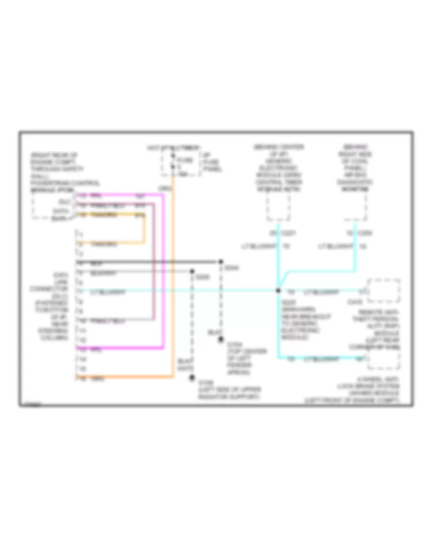
COMPUTER DATA LINES
Computer Data Lines for Ford Ranger Splash 1997
 https://portal-diagnostov.com/license.html
Automotive Electricians Portal FZCO
Automotive Electricians Portal FZCO
https://portal-diagnostov.com/license.html
https://portal-diagnostov.com/license.html
Automotive Electricians Portal FZCO
Automotive Electricians Portal FZCOList of elements for Computer Data Lines for Ford Ranger Splash 1997:
- (behind center of i/p) generic electronic module (gem)/ central timer module (ctm)
- (behind right side of cowl panel) air bag diagnostic monitor
- (right rear of engine compt, through safety wall) powertrain control module (pcm)
- 4 wheel anti- lock brake system (4wabs) module (left front of engine compt)
- C221
- C250
- C410
- Data +
- Data -
- Data link connector (dlc) (fastened to bottom of i/p, near steering column)
- Dlc
- Fuse 10a
- G104 (top center of left fender apron)
- G108 (left side of upper radiator support)
- Hot at all times
- I/p fuse panel
- Remote anti- theft person- ality (rap) module (left rear corner of cab)
- S205
- S225 (main harn, near breakout to generic electronic module)
- S244
CRUISE CONTROL
Cruise Control Wiring Diagram for Ford Ranger Splash 1997
 https://portal-diagnostov.com/license.html
Automotive Electricians Portal FZCO
Automotive Electricians Portal FZCO
https://portal-diagnostov.com/license.html
https://portal-diagnostov.com/license.html
Automotive Electricians Portal FZCO
Automotive Electricians Portal FZCOList of elements for Cruise Control Wiring Diagram for Ford Ranger Splash 1997:
- (engine sensor harness, 2.3l: near breakout to throttle position sensor; 3.0l: left rear of engine compt; 4.0l: near breakout to fuel injector 6) s111
- 1.4k ohms
- 15a
- 7.5a
- A/t
- Accel
- Anti- theft system
- Brake on/off (boo) switch (on brake pedal support)
- Brake press in
- Brake pressure switch (left side of engine compart- ment)
- C214
- C215
- C219
- C221
- C224
- C409
- Clock- spring assembly (top of steering column)
- Clutch pedal position (cpp) switch (top of clutch pedal support)
- Clutch pedal position (cpp) switch jumper (left of steering column)
- Coast
- Control sw gnd
- Control sw in
- Driver's airbag
- Engine compartment fuse/relay box
- Fuse 10
- Fuse 13
- G104 (top center of left fender apron)
- G108 (left side of upper radiator support)
- Generic electronic module (gem)/ central timer module (ctm) (behind center of i/p)
- Ground
- Horn maxi fuse 11 20a
- Horn nca switches
- Horn relay (in eng compt fuse/ panel)
- Hot at all times
- Hot in run
- I/p fuse panel
- Ign
- Ignition key warning switch
- Ind ctrl
- Instru- ment cluster
- Instrument cluster
- Interior lights system
- M/t
- Main light switch
- Nca
- Off
- Ohms
- Powertrain control module (pcm) (right rear of engine compartment, through safety wall)
- Remote anti- theft person- ality (rap) module (left rear corner of cab)
- Resume
- S110
- S135
- S136
- S139 (dash to head- lamp harn, left side of safety wall)
- S141
- S205
- S229 (main harness, behind top left side of i/p)
- Set/
- Speed control ind
- Speed control servo/ amplifier assembly (right rear of engine compartment)
- Speed control switch assembly
- Speedo
- Steering assembly
- Vehicle speed in
- Vehicle speed sensor (vss) (left rear of trans/ transfer case)
- Vss in
ENGINE PERFORMANCE
2.3L
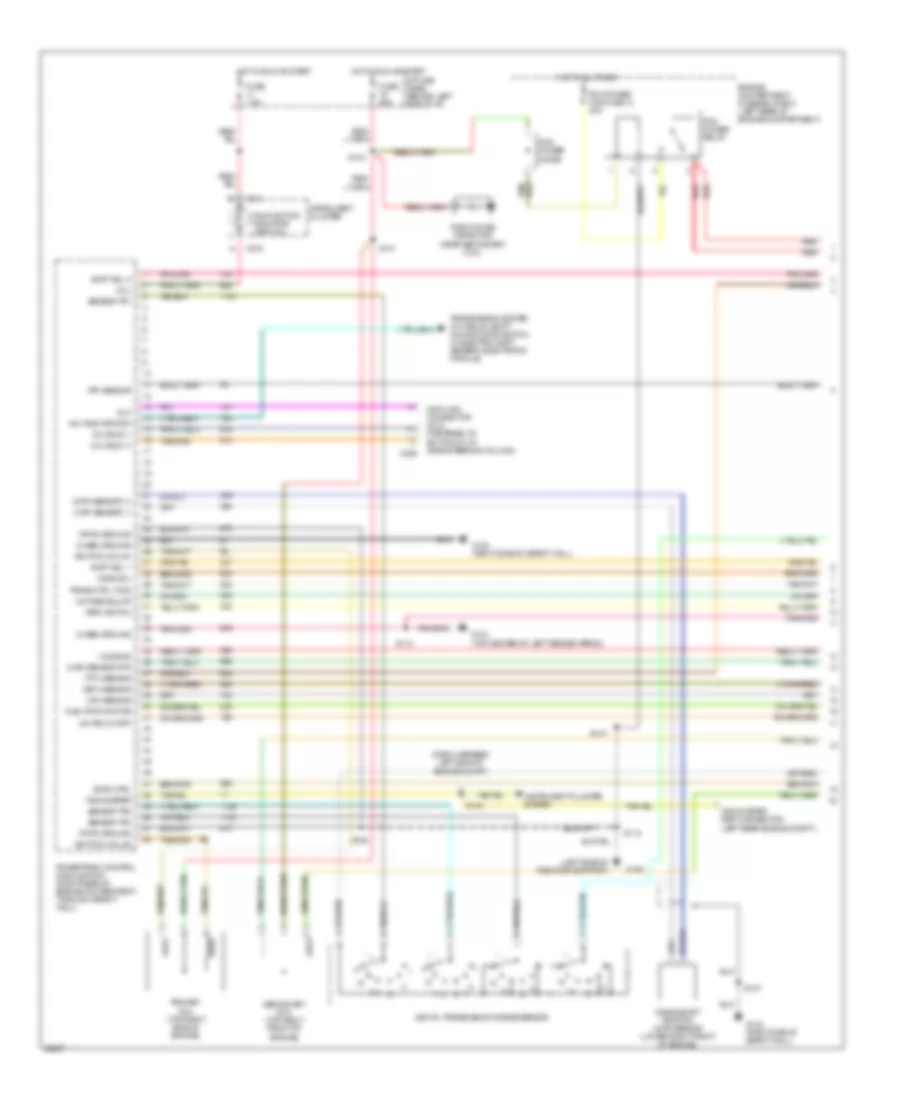
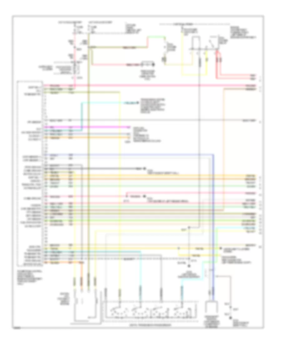
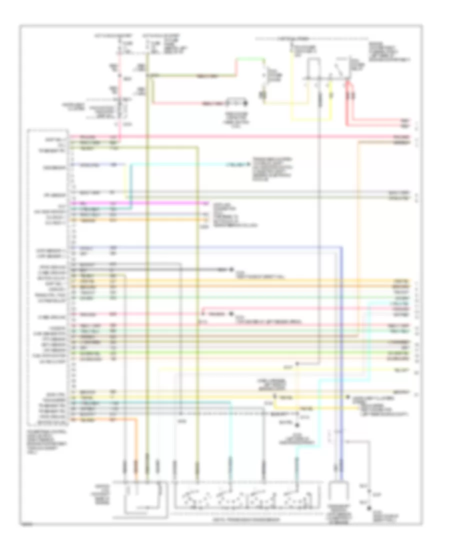
2.3L, Engine Performance Wiring Diagrams (1 of 4) for Ford Ranger Splash 1997
 https://portal-diagnostov.com/license.html
Automotive Electricians Portal FZCO
Automotive Electricians Portal FZCO
https://portal-diagnostov.com/license.html
https://portal-diagnostov.com/license.html
Automotive Electricians Portal FZCO
Automotive Electricians Portal FZCOList of elements for 2.3L, Engine Performance Wiring Diagrams (1 of 4) for Ford Ranger Splash 1997:
- (case) ground
- (ckp) sensor (+)
- (ckp) sensor (-)
- (css) sol
- (dash harness, left side of engine compt)
- (ect) sensor
- (evr) ctrl
- (ho2s) #2
- (iat) sensor
- (left side of radiator support)
- (maf) sensor rtn
- (mil)
- (pf) sensor
- (psp) switch
- (pwr) ground
- (tft) sensor
- 4x4 indicator sw
- A/c psi cutoff
- C209
- C214
- C216
- Crankshaft position (ckp) sensor (lower right front of engine)
- Data link connector (dlc) (fastened to bottom of i/p, near steering column)
- Digital transmission range sensor
- Dlc
- Dlc bus (+)
- Dlc bus (-)
- Engine compartment fuse/relay box (left rear of engine compartment)
- Fuel pmp monitor
- Fuse 25a
- Fuse 7.5a
- G104 (top center of left fender apron)
- G108
- G123 (right side of safety wall)
- Hot at all times
- Hot in run or start
- I/p fuse panel (behind left side of i/p)
- Ignition coil #1
- Ignition coil #2
- Instrument cluster
- Instrument cluster system
- Malfunction indicator lamp (mil)
- Octane adjust
- Pcm power diode
- Pcm power maxi fuse 13 30a
- Pcm power relay
- Powertrain control module (pcm) (right rear of engine compartment, through safety wall)
- Primary coil (top right side of engine)
- Radio noise capacitor (near secondary coil)
- Red
- S101
- S106
- S107
- S110
- S118
- S134
- S144
- S147
- Secondary coil (top right front of engine)
- Sensor tr1
- Sensor tr2
- Sensor tr4
- Shift sol 1
- Shift sol 2
- Tachometer
- Tachometer test connector (left rear engine compt.)
- Trans ctrl (tcs)
- Transmission system (w/ manual shift: 4x4 indicator switch; w/ electric shift: generic electronic module)
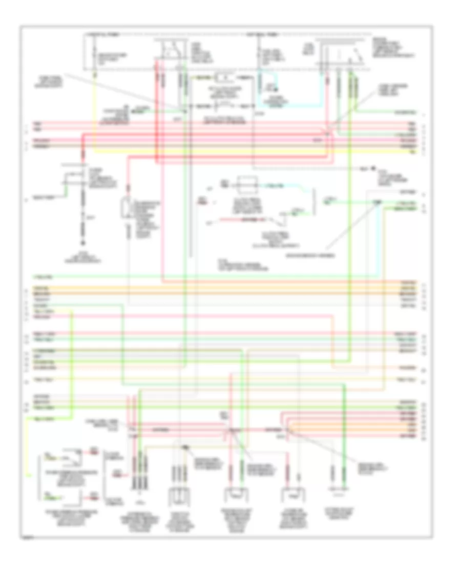
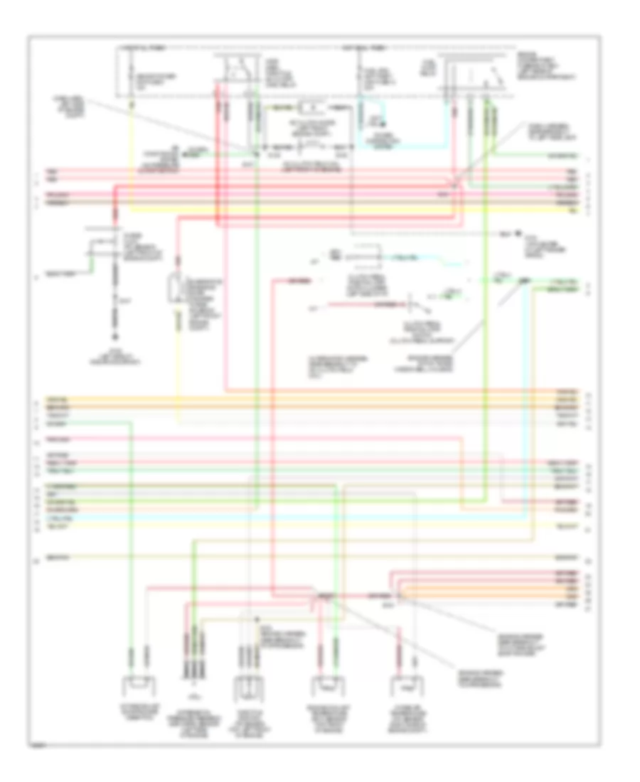
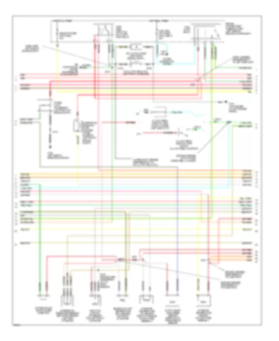
2.3L, Engine Performance Wiring Diagrams (2 of 4) for Ford Ranger Splash 1997
 https://portal-diagnostov.com/license.html
Automotive Electricians Portal FZCO
Automotive Electricians Portal FZCO
https://portal-diagnostov.com/license.html
https://portal-diagnostov.com/license.html
Automotive Electricians Portal FZCO
Automotive Electricians Portal FZCOList of elements for 2.3L, Engine Performance Wiring Diagrams (2 of 4) for Ford Ranger Splash 1997:
- (dash harn, near breakout to g102)
- (dash harness, near left headlamp)
- (dash panel, left side of engine compt)
- (engine harn, near breakout to g123)
- (engine harn, near breakout to iat sensor)
- (engine sensor harness)
- A/c clutch diode (left front engine compt.)
- A/c clutch field coil (left front of engine)
- A/t
- Air conditioning system (a/c pressure cutoff switch)
- Clutch pedal position (cpp) switch (clutch pedal support)
- Clutch pedal position (cpp) switch jumper (left side of i/p)
- Differential pressure feedback egr (dpfe) sensor (right rear of engine)
- Engine compartment fuse/relay box (left rear of engine compartment)
- Engine coolant temperature (ect) sensor (top right front of engine)
- Evaporative emissions (evap) canister purge solenoid (left front engine compt.)
- Fuel pump relay
- Fuel sys/ anti-theft maxi fuse 12 20a
- G104 (top center of left fender apron)
- G108 (left side of radiator support)
- Hot at all times
- Intake air temperature (iat) sensor (right side of engine compt.)
- M/t
- Memory power mini fuse 5 15a
- Nca
- Octane adjust shorting bar (near pcm)
- Power distribution system
- Power steering pressure (psp) switch (left front of engine compt.)
- Power steering pressure (psp) switch jumper (left front of engine compt.)
- Purge flow (pf) sensor (left front of engine compt.)
- Red
- S100
- S102
- S103
- S108
- S121
- S128
- S137
- S145 (alternator harness, top left front of engine)
- S146
- S147
- Throttle position (tp) sensor (top right side of engine)
- W/ pwr steering
- W/o pwr steering
- Wide open throttle a/c cutoff (wac) relay
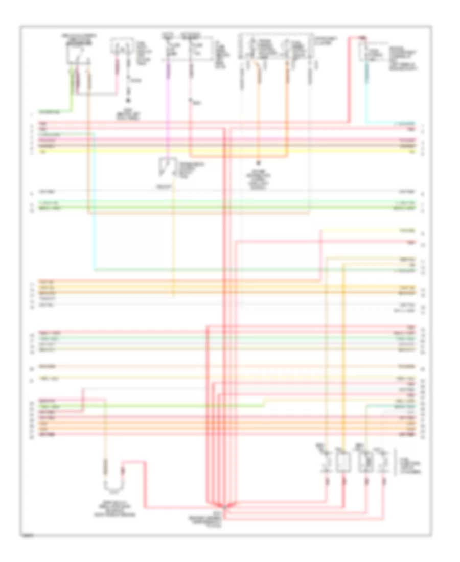
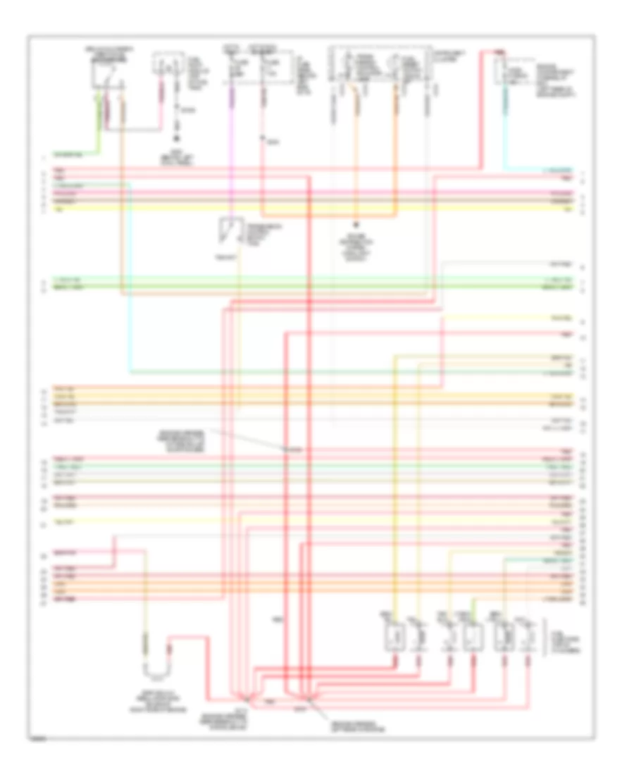
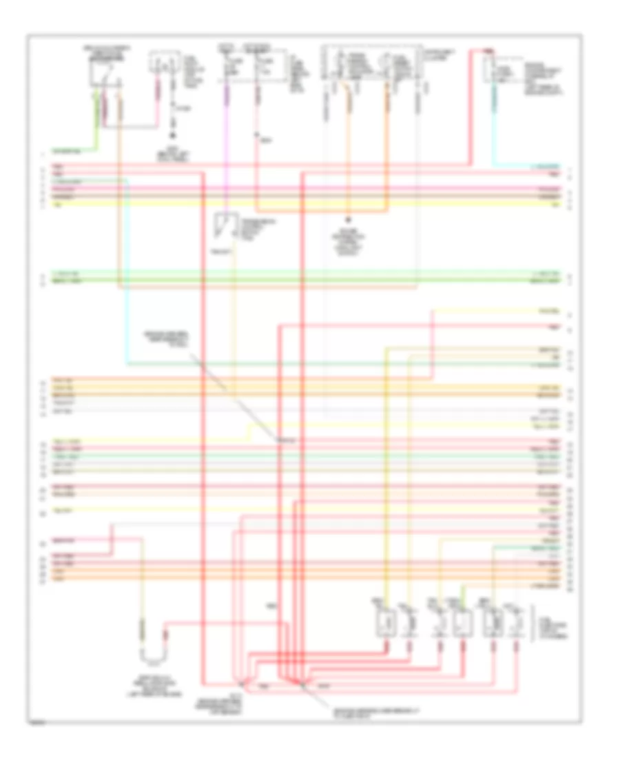
2.3L, Engine Performance Wiring Diagrams (3 of 4) for Ford Ranger Splash 1997
 https://portal-diagnostov.com/license.html
Automotive Electricians Portal FZCO
Automotive Electricians Portal FZCO
https://portal-diagnostov.com/license.html
https://portal-diagnostov.com/license.html
Automotive Electricians Portal FZCO
Automotive Electricians Portal FZCOList of elements for 2.3L, Engine Performance Wiring Diagrams (3 of 4) for Ford Ranger Splash 1997:
- (below glove box) inertia fuel shut-off (ifs)
- C214
- Egr vacuum regulator (evr) solenoid (right side of engine)
- Engine compartment fuse/relay box (left rear of engine compt.)
- Fuel injectors (top of cylinders)
- Fuel pump module (top of fuel tank)
- Fuel reset switch indica- or c214
- Fuse 15a
- Fuse 7.5a
- G200 (behind left cowl panel)
- Ho2s fuse 20 15a
- Hot in run
- Hot in run or start
- I/p fuse panel (behind left side of i/p)
- Instrument cluster
- Power distribution system (main light switch)
- Red
- S1005
- S104 (engine harness, near breakout to g123)
- S240
- Tan
- Trans- mission control indicator lamp
- Transmission control switch (tcs)
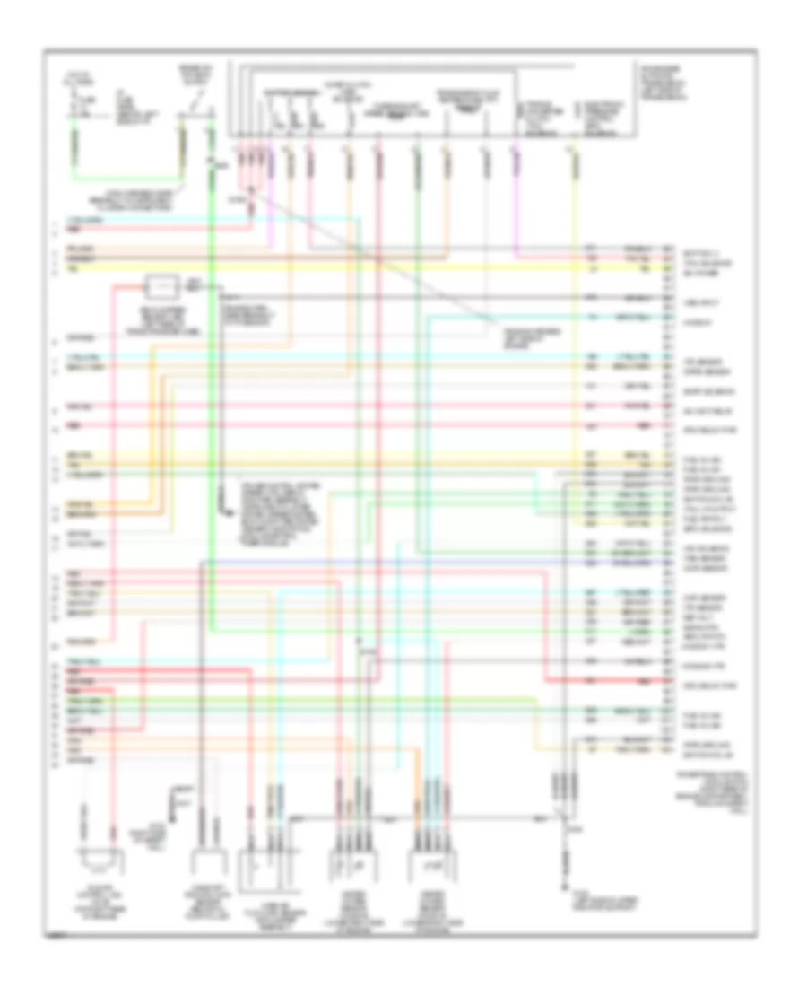
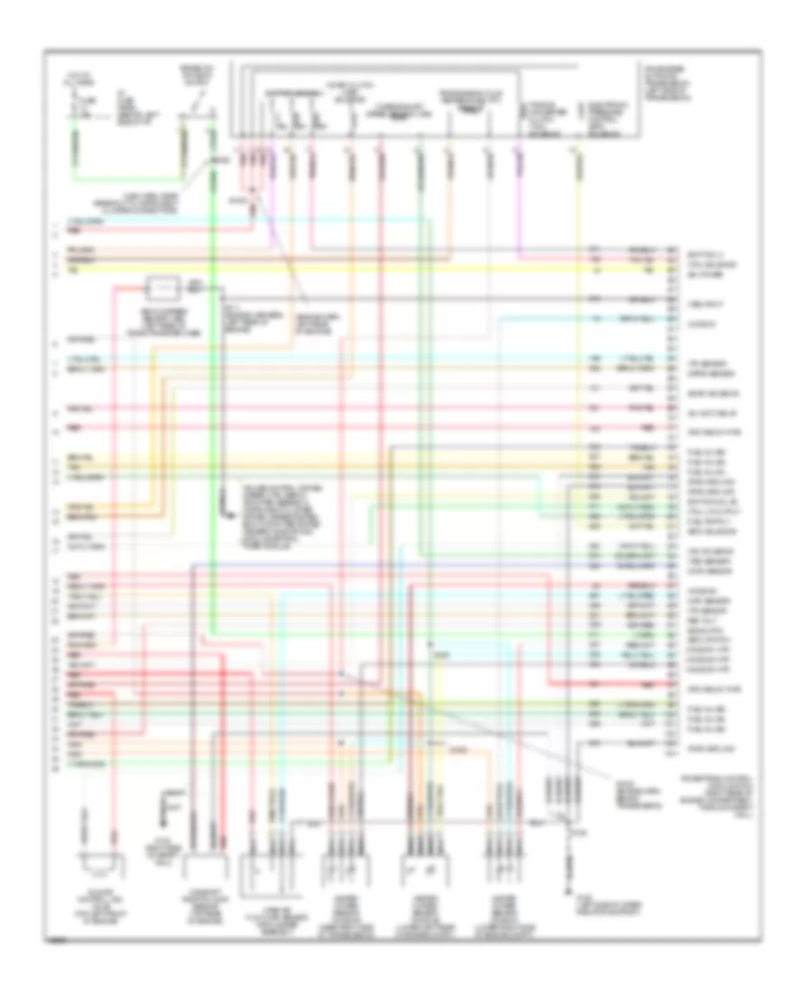
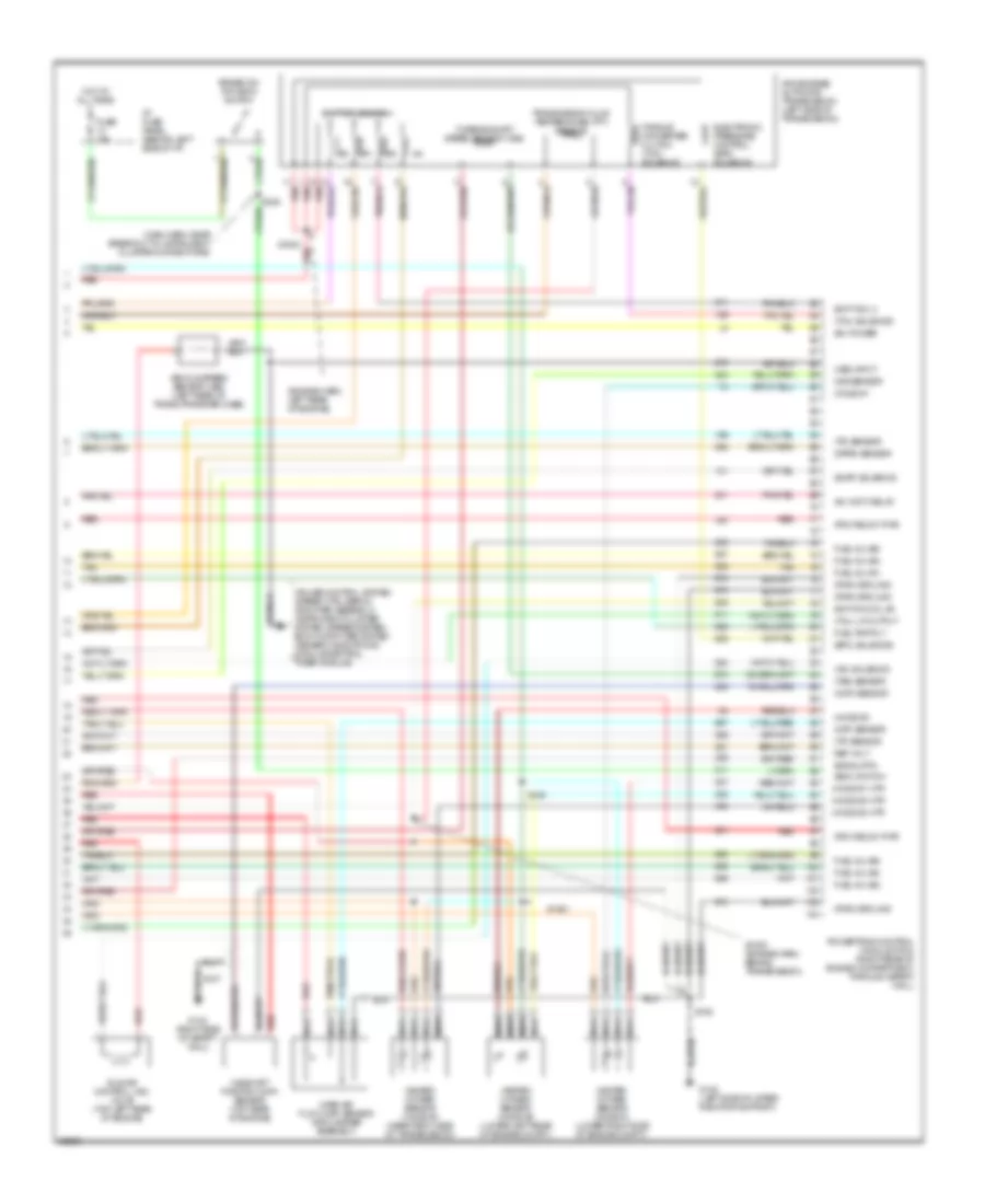
2.3L, Engine Performance Wiring Diagrams (4 of 4) for Ford Ranger Splash 1997
 https://portal-diagnostov.com/license.html
Automotive Electricians Portal FZCO
Automotive Electricians Portal FZCO
https://portal-diagnostov.com/license.html
https://portal-diagnostov.com/license.html
Automotive Electricians Portal FZCO
Automotive Electricians Portal FZCOList of elements for 2.3L, Engine Performance Wiring Diagrams (4 of 4) for Ford Ranger Splash 1997:
- (b+) power
- (boo) switch
- (cmp) sensor
- (dpfe) sensor
- (engine harn, near breakout to tp sensor)
- (engine harness, left side of engine)
- (epc) solenoid
- (evap) solenoid
- (ho2s) #1
- (ho2s) #1 htr
- (ho2s) #2 htr
- (iac) solenoid
- (maf) sensor
- (main harness, near breakout to instrument cluster connectors)
- (pcm relay) pwr
- (pwr) ground
- (tcc) solenoid
- (tcil) lp output
- (tp) sensor
- (tr) sensor
- (tss) sensor
- (vss) input
- 4r44e/4r55e automatic transmission (left side of transmission)
- A/c (wot) relay
- Brake on/ off (boo) switch
- Camshaft position (cmp) sensor (behind oil pump pulley)
- Coast clutch (css) solenoid
- Cruise control system (speed ctrl servo/ amplifier assembly), instrument cluster system (speedometer), body computer system (generic electronic module/central timer module)
- Electronic pressure control (epc) solenoid
- Fuel inj (#1)
- Fuel inj (#2)
- Fuel inj (#3)
- Fuel inj (#4)
- Fuel pmp rly
- Fuse 15a
- G108 (left side of upper radiator support)
- G123 (right side of safety wall)
- Heated oxygen sensor (ho2s) #1 (lower right side of engine)
- Heated oxygen sensor (ho2s) #2 (lower right side of engine)
- Hot at all times
- I/p fuse panel (behind left side of i/p)
- Idle air control (iac) valve (top right rear of engine)
- Ignition coil #3
- Ignition coil #4
- Mass air flow (maf) sensor (air cleaner assembly)
- Nca
- Powertrain control module (pcm) (right rear of engine compartment, through safety wall)
- Red
- Ref volt
- S1002 red
- S106
- S107
- S109
- S111
- S228
- Shift sol 3
- Shift solenoids
- Signal rtn
- Tan
- Torque converter clutch (tcc) solenoid
- Transmission fluid temperature (tft) sensor
- Turbine shaft speed sensor (tss)
- Vehicle speed sensor (vss) (left rear of trans./transfer case)
3.0L
3.0L, Engine Performance Wiring Diagrams (1 of 4) for Ford Ranger Splash 1997
 https://portal-diagnostov.com/license.html
Automotive Electricians Portal FZCO
Automotive Electricians Portal FZCO
https://portal-diagnostov.com/license.html
https://portal-diagnostov.com/license.html
Automotive Electricians Portal FZCO
Automotive Electricians Portal FZCOList of elements for 3.0L, Engine Performance Wiring Diagrams (1 of 4) for Ford Ranger Splash 1997:
- (case) ground
- (ckp) sensor (+)
- (ckp) sensor (-)
- (css) sol
- (ect) sensor
- (evr) ctrl
- (ho2s) #3
- (iat) sensor
- (maf) sensor rtn
- (mil)
- (pf) sensor
- (pwr) ground
- (tft) sensor
- 4x4 indicator sw
- A/c psi cutoff
- C209
- C214
- C216
- Crankshaft position (ckp) sensor (lower front of engine)
- Data link connector (dlc) (fastened to bottom of i/p, near steering column)
- Digital transmission range sensor
- Dlc
- Dlc bus (+)
- Dlc bus (-)
- Engine compartment fuse/relay box (left rear of engine compartment)
- Fuel pmp monitor
- Fuse 25a
- Fuse 7.5a
- G104 (top center of left fender apron)
- G108 (left side of radiator support)
- G123 (right side of safety wall)
- Hot at all times
- Hot in run or start
- I/p fuse panel (behind left side of i/p)
- Ignition coil #1
- Ignition coil #3
- Ignition coil (top right side of engine)
- Instrument cluster
- Instrument clusters system
- Malfunction indicator lamp (mil)
- Octane adjust
- Pcm power diode
- Pcm power maxi fuse 13 30a
- Pcm power relay
- Powertrain control module (pcm) (right rear of engine compartment, through safety wall)
- Radio noise capacitor (near ignition coil)
- Red
- S106
- S107
- S110
- S118
- S134
- S147
- S240
- Shift sol 1
- Shift sol 2
- Tachometer
- Tachometer test connector (left rear engine compt.)
- Tr sensor tr1
- Tr sensor tr2
- Tr sensor tr4
- Trans ctrl (tcs)
- Transmission system (w/ manual shift: 4x4 indicator switch; w/ electric shift: generic electronic module)
3.0L, Engine Performance Wiring Diagrams (2 of 4) for Ford Ranger Splash 1997
 https://portal-diagnostov.com/license.html
Automotive Electricians Portal FZCO
Automotive Electricians Portal FZCO
https://portal-diagnostov.com/license.html
https://portal-diagnostov.com/license.html
Automotive Electricians Portal FZCO
Automotive Electricians Portal FZCOList of elements for 3.0L, Engine Performance Wiring Diagrams (2 of 4) for Ford Ranger Splash 1997:
- (alternator harness, near breakout to a/c clutch field coil)
- (dash harn, left side of engine compt)
- (dash harness, near breakout to left headlamp)
- (engine harness, near breakout to dpfe sensor)
- (engine harness, near breakout to octane adjust shorting bar)
- (engine harness, top of trans- mission bell housing)
- A/c clutch diode (left front engine compt.)
- A/c clutch field coil (left front of engine)
- A/t
- Air conditioning system (a/c pressure cutoff switch)
- Clutch pedal position (cpp) switch (clutch pedal support)
- Clutch pedal position (cpp) switch jumper (left side of i/p)
- Differential pressure feedback egr (dpfe) sensor (left side of engine)
- Engine compartment fuse/relay box (left rear of engine compartment)
- Engine coolant temperature (ect) sensor (top front of engine)
- Evaporative emissions (evap) canister purge solenoid (left front engine compt.)
- Fuel pump relay
- Fuel sys/ anti-theft maxi fuse 12 20a
- G104 (top center of left fender apron)
- G108 (left side of radiator support)
- Hot at all times
- Intake air temperature (iat) sensor (right side of engine compt.)
- M/t
- Memory power mini fuse 5 15a
- Nca
- Octane adjust shorting bar (near pcm)
- Power distribution system
- Purge flow (pf) sensor (left front of engine compt.)
- Red
- S100 (engine harness, near breakout to dpfe sensor)
- S102
- S103
- S108
- S121
- S137
- S145
- S146
- S147
- Throttle position (tp) sensor (top left front of engine)
- Wide open throttle a/c cutoff (wac) relay
3.0L, Engine Performance Wiring Diagrams (3 of 4) for Ford Ranger Splash 1997
 https://portal-diagnostov.com/license.html
Automotive Electricians Portal FZCO
Automotive Electricians Portal FZCO
https://portal-diagnostov.com/license.html
https://portal-diagnostov.com/license.html
Automotive Electricians Portal FZCO
Automotive Electricians Portal FZCOList of elements for 3.0L, Engine Performance Wiring Diagrams (3 of 4) for Ford Ranger Splash 1997:
- (below glove box) inertia fuel shut-off (ifs)
- (engine harness, left rear of engine)
- (engine harness, near breakout to octane adjust shorting bar)
- C214
- Egr vacuum regulator (evr) solenoid (right side of engine)
- Engine compartment fuse/relay box (left rear of engine compt.)
- Fuel injectors (top of cylinders)
- Fuel pump module (top of fuel tank)
- Fuel reset switch indica- or c214
- Fuse 15a
- Fuse 7.5a
- G200 (behind left cowl panel)
- Ho2s fuse 20 15a
- Hot in run
- Hot in run or start
- I/p fuse panel (behind left side of i/p)
- Instrument cluster
- Power distribution system (main light switch)
- Red
- S1005
- S104
- S112
- S113 (engine harness, near breakout to evr solenoid)
- S240
- Tan
- Trans- mission control indicator lamp
- Transmission control switch (tcs)
3.0L, Engine Performance Wiring Diagrams (4 of 4) for Ford Ranger Splash 1997
 https://portal-diagnostov.com/license.html
Automotive Electricians Portal FZCO
Automotive Electricians Portal FZCO
https://portal-diagnostov.com/license.html
https://portal-diagnostov.com/license.html
Automotive Electricians Portal FZCO
Automotive Electricians Portal FZCOList of elements for 3.0L, Engine Performance Wiring Diagrams (4 of 4) for Ford Ranger Splash 1997:
- (b+) power
- (boo) switch
- (cmp) sensor
- (dpfe) sensor
- (engine harn, left rear of enigine)
- (epc) solenoid
- (evap) solenoid
- (ho2s) #1
- (ho2s) #1 htr
- (ho2s) #2
- (ho2s) #2 htr
- (ho2s) #3 htr
- (iac) solenoid
- (maf) sensor
- (main harn, near breakout to instrument cluster connectors)
- (pcm relay) pwr
- (pwr) ground
- (tcc) solenoid
- (tcil) lp output
- (tp) sensor
- (tr) sensor
- (tss) sensor
- (vss) input
- 4r44e/4r55e automatic transmission (left side of transmission)
- A/c (wot) relay
- Brake on/ off (boo) switch
- Camshaft position (cmp) sensor (top rear of engine)
- Coast clutch (css) solenoid
- Cruise control system (speed ctrl servo/ amplifier assembly), instrument cluster system (speedometer), body computer system (generic electronic module/central timer module)
- Electronic pressure control (epc) solenoid
- Fuel inj (#1)
- Fuel inj (#2)
- Fuel inj (#3)
- Fuel inj (#4)
- Fuel inj (#5)
- Fuel inj (#6)
- Fuel pmp rly
- Fuse 15a
- G108 (left side of upper radiator support)
- G123 (right side of safety wall)
- Heated oxygen sensor (ho2s) #1 (lower right side of engine compt.)
- Heated oxygen sensor (ho2s) #2 (lower left rear of engine compt.)
- Heated oxygen sensor (ho2s) #3 (near right side of transmission)
- Hot at all times
- I/p fuse panel (behind left side of i/p)
- Idle air control (iac) valve (top left front of engine)
- Ignition coil #2
- Mass air flow (maf) sensor (air cleaner assembly)
- Nca
- Powertrain control module (pcm) (right rear of engine compartment, through safety wall)
- Red
- Ref volt
- S1000 (engine harn, behind transmission)
- S1001
- S1002 red
- S106
- S107
- S109
- S111 (engine harness, left rear of engine)
- S228
- Shift sol 3
- Shift solenoids
- Signal rtn
- Tan
- Torque converter clutch (tcc) solenoid
- Transmission fluid temperature (tft) sensor
- Turbine shaft speed sensor (tss)
- Vehicle speed sensor (vss) (left rear of trans./transfer case)
4.0L
4.0L, Engine Performance Wiring Diagrams (1 of 4) for Ford Ranger Splash 1997
 https://portal-diagnostov.com/license.html
Automotive Electricians Portal FZCO
Automotive Electricians Portal FZCO
https://portal-diagnostov.com/license.html
https://portal-diagnostov.com/license.html
Automotive Electricians Portal FZCO
Automotive Electricians Portal FZCOList of elements for 4.0L, Engine Performance Wiring Diagrams (1 of 4) for Ford Ranger Splash 1997:
- (case) ground
- (ckp) sensor (+)
- (ckp) sensor (-)
- (css) sol
- (dash harness, left side of engine compt)
- (ect) sensor
- (evr) ctrl
- (ho2s) #3
- (iat) sensor
- (maf) sensor rtn
- (mil)
- (pf) sensor
- (pwr) ground
- (tft) sensor
- 4x4 indicator sw
- A/c psi cutoff
- C209
- C214
- C216
- Crankshaft position (ckp) sensor (lower front of engine)
- Data link connector (dlc) (fastened to bottom of i/p, near steering column)
- Digital transmission range sensor
- Dlc
- Dlc bus (+)
- Dlc bus (-)
- Engine compartment fuse/relay box (left rear of engine compartment)
- Fuel pmp monitor
- Fuse 25a
- Fuse 7.5a
- G104 (top center of left fender apron)
- G108 (left side of radiator support)
- G123 (right side of safety wall
- G123 (right side of safety wall)
- Hot at all times
- Hot in run or start
- I/p fuse panel (behind left side of i/p)
- Ignition coil #1
- Ignition coil #2
- Ignition coil (top right rear of engine)
- Instrument cluster
- Instrument clusters system
- Malfunction indicator lamp (mil)
- Octane adjust
- Oss sensor
- Pcm power diode
- Pcm power maxi fuse 13 30a
- Pcm power relay
- Powertrain control module (pcm) (right rear of engine compartment, through safety wall)
- Radio noise capacitor (near ignition coil)
- Red
- S106
- S107
- S110
- S118
- S134
- S144
- S147
- S240
- Shift sol 1
- Shift sol 2
- Tachometer
- Tachometer test connector (left rear engine compt.)
- Tr sensor tr1
- Tr sensor tr2
- Tr sensor tr4
- Trans ctrl (tcs)
- Transmission system (w/ manual shift: 4x4 indicator switch; w/ electric shift: generic electronic module)
4.0L, Engine Performance Wiring Diagrams (2 of 4) for Ford Ranger Splash 1997
 https://portal-diagnostov.com/license.html
Automotive Electricians Portal FZCO
Automotive Electricians Portal FZCO
https://portal-diagnostov.com/license.html
https://portal-diagnostov.com/license.html
Automotive Electricians Portal FZCO
Automotive Electricians Portal FZCOList of elements for 4.0L, Engine Performance Wiring Diagrams (2 of 4) for Ford Ranger Splash 1997:
- (alternator harness, near breakout to a/c clutch field coil)
- (dash harn, left side of engine compt)
- (dash harness, near breakout to left headlamp)
- (engine harness, near breakout to injector 5)
- (engine harness, near breakout to injector 6)
- (engine harness, top of trans- mission bell housing)
- A/c clutch diode (left front engine compt.)
- A/c clutch field coil (left front of engine)
- A/t
- Air conditioning system (a/c pressure cutoff switch)
- Clutch pedal position (cpp) switch (clutch pedal support)
- Clutch pedal position (cpp) switch jumper (left side of i/p)
- Differential pressure feedback egr (dpfe) sensor (left side of engine)
- Engine compartment fuse/relay box (left rear of engine compartment)
- Engine coolant temperature (ect) sensor (top front of engine)
- Evaporative emissions (evap) canister purge solenoid (left front engine compt.)
- Fuel pump relay
- Fuel sys/ anti-theft maxi fuse 12 20a
- G104 (top center of left fender apron)
- G108 (left side of radiator support)
- Hot at all times
- Intake air temperature (iat) sensor (front of engine, on air intake assembly)
- Intake air temperature sensor (on air intake assembly)
- M/t
- Memory power mini fuse 5 15a
- Nca
- Octane adjust shorting bar (near pcm)
- Output shaft (oss) speed sensor (near digital transmission sensor)
- Power distribution system
- Purge flow (pf) sensor (left front of engine compt.)
- Red
- S100 (engine harn, near break- out to dpfe sensor)
- S102
- S103
- S108
- S121
- S137
- S145
- S146
- S147
- Throttle position (tp) sensor (top left front of engine)
- Wide open throttle a/c cutoff (wac) relay
4.0L, Engine Performance Wiring Diagrams (3 of 4) for Ford Ranger Splash 1997
 https://portal-diagnostov.com/license.html
Automotive Electricians Portal FZCO
Automotive Electricians Portal FZCO
https://portal-diagnostov.com/license.html
https://portal-diagnostov.com/license.html
Automotive Electricians Portal FZCO
Automotive Electricians Portal FZCOList of elements for 4.0L, Engine Performance Wiring Diagrams (3 of 4) for Ford Ranger Splash 1997:
- (below glove box) inertia fuel shut-off (ifs)
- (engine harness, near breakout to injector 5)
- (engine harness, near breakout to pcm)
- C214
- Egr vacuum regulator (evr) solenoid (left rear of engine)
- Engine compartment fuse/relay box (left rear of engine compt.)
- Fuel injectors (top of cylinders)
- Fuel pump module (top of fuel tank)
- Fuel reset switch indica- or c214
- Fuse 15a
- Fuse 7.5a
- G200 (behind left cowl panel)
- Ho2s fuse 3 15a
- Hot in run
- Hot in run or start
- I/p fuse panel (behind left side of i/p)
- Instrument cluster
- Power distribution system (main light switch)
- Red
- S1005
- S104
- S112
- S113 (engine harness, near breakout to maf sensor)
- S240
- Tan
- Trans- mission control indicator lamp
- Transmission control switch (tcs)
4.0L, Engine Performance Wiring Diagrams (4 of 4) for Ford Ranger Splash 1997
 https://portal-diagnostov.com/license.html
Automotive Electricians Portal FZCO
Automotive Electricians Portal FZCO
https://portal-diagnostov.com/license.html
https://portal-diagnostov.com/license.html
Automotive Electricians Portal FZCO
Automotive Electricians Portal FZCOList of elements for 4.0L, Engine Performance Wiring Diagrams (4 of 4) for Ford Ranger Splash 1997:
- (b+) power
- (boo) switch
- (cmp) sensor
- (dpfe) sensor
- (engine harn, left rear of engine)
- (epc) solenoid
- (evap) solenoid
- (ho2s) #1
- (ho2s) #1 htr
- (ho2s) #2
- (ho2s) #2 htr
- (ho2s) #3 htr
- (iac) solenoid
- (maf) sensor
- (main harn, near breakout to instrument cluster connectors)
- (pcm relay) pwr
- (pwr) ground
- (tcc) solenoid
- (tcil) lp output
- (tp) sensor
- (tr) sensor
- (tss) sensor
- (vss) input
- 4r44e/4r55e automatic transmission (left side of transmission)
- A/c (wot) relay
- Brake on/ off (boo) switch
- Camshaft position (cmp) sensor (top rear of engine)
- Cruise control system (speed ctrl servo/ amplifier assembly), instrument cluster system (speedometer), body computer system (generic electronic module/central timer module)
- Electronic pressure control (epc) solenoid
- Fuel inj (#1)
- Fuel inj (#2)
- Fuel inj (#3)
- Fuel inj (#4)
- Fuel inj (#5)
- Fuel inj (#6)
- Fuel pmp rly
- Fuse 15a
- G108 (left side of upper radiator support)
- G123 (right side of safety wall)
- Heated oxygen sensor (ho2s) #1 (lower right side of engine compt.)
- Heated oxygen sensor (ho2s) #2 (lower left rear of engine compt.)
- Heated oxygen sensor (ho2s) #3 (near right side of transmission)
- Hot at all times
- I/p fuse panel (behind left side of i/p)
- Idle air control (iac) valve (top left rear of engine)
- Ignition coil #3
- Mass air flow (maf) sensor (air cleaner assembly)
- Nca
- Ods sensor
- Powertrain control module (pcm) (right rear of engine compartment, through safety wall)
- Red
- Ref volt
- S1000 (engine harn, behind transmission)
- S1001
- S1002
- S106
- S107
- S109
- S228
- Shift sol 3
- Shift solenoids
- Signal rtn
- Tan
- Torque converter clutch (tcc) solenoid
- Transmission fluid temperature (tft) sensor
- Turbine shaft speed sensor (tss)
- Vehicle speed sensor (vss) (left rear of trans./transfer case)
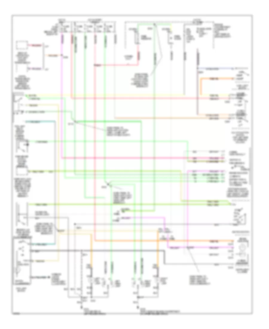
EXTERIOR LIGHTS
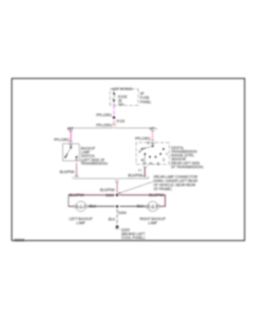
Back-up Lamps Wiring Diagram for Ford Ranger Splash 1997
 https://portal-diagnostov.com/license.html
Automotive Electricians Portal FZCO
Automotive Electricians Portal FZCO
https://portal-diagnostov.com/license.html
https://portal-diagnostov.com/license.html
Automotive Electricians Portal FZCO
Automotive Electricians Portal FZCOList of elements for Back-up Lamps Wiring Diagram for Ford Ranger Splash 1997:
- (rear lamp connector harn, under left rear of vehicle, near rear of frame)
- A/t
- Backup lamp switch (left side of transmission)
- Digital transmission range (dtr) sensor (rear left side of transmission)
- Fuse 10a
- G200 (behind left cowl panel)
- Hot in run
- I/p fuse panel
- Left backup lamp
- M/t
- Right backup lamp
- S126
- S400
- S403
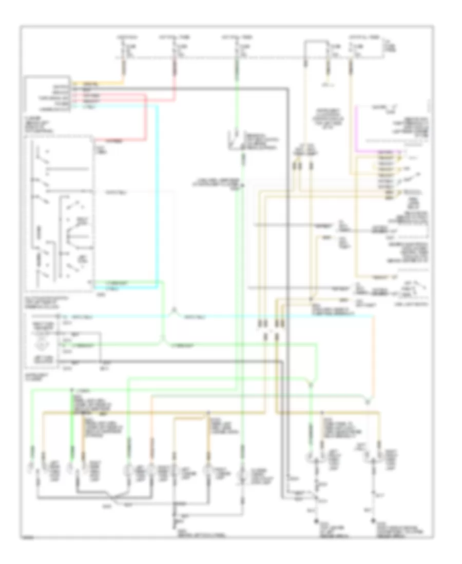
Exterior Lamps Wiring Diagram for Ford Ranger Splash 1997
 https://portal-diagnostov.com/license.html
Automotive Electricians Portal FZCO
Automotive Electricians Portal FZCO
https://portal-diagnostov.com/license.html
https://portal-diagnostov.com/license.html
Automotive Electricians Portal FZCO
Automotive Electricians Portal FZCOList of elements for Exterior Lamps Wiring Diagram for Ford Ranger Splash 1997:
- (main harn, near rear of instrument cluster) s228
- (not used)
- Anti- theft
- Brake on/ off (boo) switch (on brake pedal support)
- C214
- C215
- C221
- C253
- C409
- Flasher (behind left side of i/p, on fuse panel)
- Fuse 10a
- Fuse 15a
- Fuse 7.5a
- G104 (top center of left fender apron)
- G105 (right side of engine compartment, on upper fender apron)
- G200 (behind left cowl panel)
- Generic electronic module (gem)/ central timer module (ctm) (behind center of i/p)
- Ground
- Hazard
- Hazard sw out
- Head
- Hot at all times
- Hot in run
- I/p fuse panel
- Ignition
- Instrument cluster
- Instrument illumination dimming module (top left side of i/p)
- Left front park/ turn lamp
- Left license lamp
- Left rear park/ stop lamp
- Left rear turn lamp
- Left turn
- Left turn indicator
- Main light switch
- Multi-function switch (top left side of steering column)
- Normal
- Off
- Outside cargo/ high mount stop lamp
- Park
- Park lamps relay
- Power
- Relay box #1 (behind i/p, right of steering column)
- Remote anti- theft personality (rap) module (left rear corner of cab)
- Right front park/ turn lamp
- Right license lamp
- Right rear park/ stop lamp
- Right rear turn lamp
- Right turn
- Right turn indicator
- S1004 (rear lamp harn, near license lamps)
- S1005
- S117
- S123
- S130 (dash panel to headlamp junct harn, near starter relay breakout)
- S131
- S214
- S234 (main harn, near i/p fuse panel breakout)
- S244
- S300
- S400
- S401 (rear lamp harn, under left rear of vehicle, near rear of frame)
- S402 (rear lamp harn, under left rear of vehicle, near rear of frame)
- Turn signal sw
- W/ anti- theft
- W/o anti- theft
- W/o anti-theft
- W/o w/ anti- theft
GROUND DISTRIBUTION
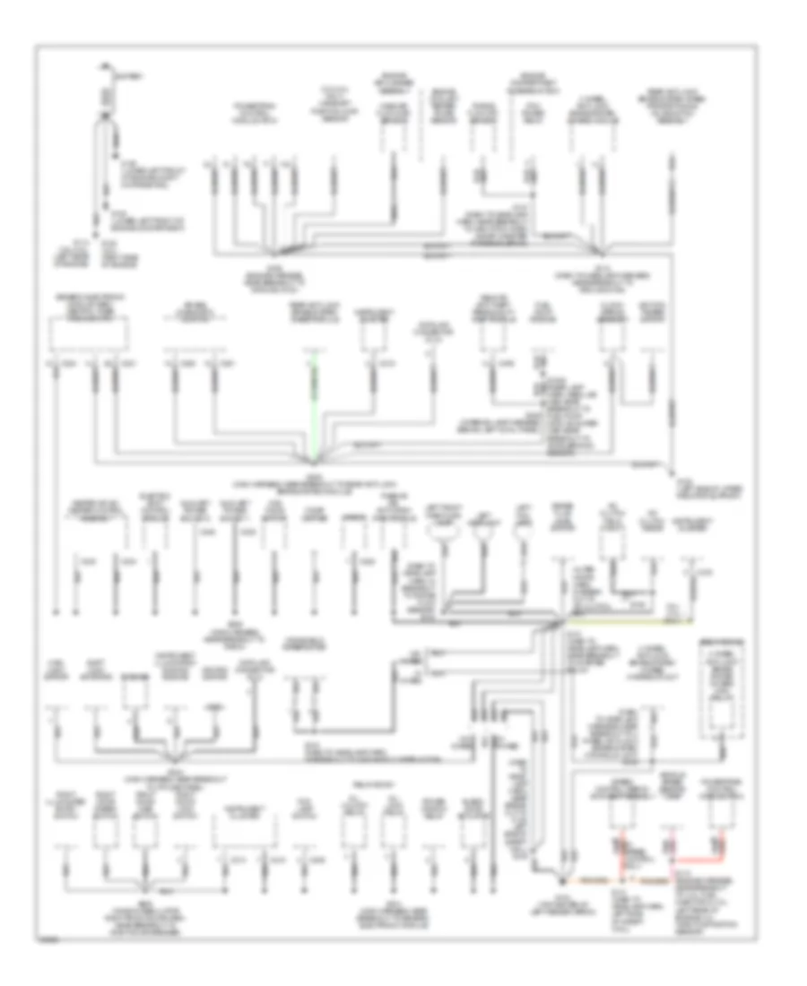
Ground Distribution Wiring Diagram (1 of 2) for Ford Ranger Splash 1997
 https://portal-diagnostov.com/license.html
Automotive Electricians Portal FZCO
Automotive Electricians Portal FZCO
https://portal-diagnostov.com/license.html
https://portal-diagnostov.com/license.html
Automotive Electricians Portal FZCO
Automotive Electricians Portal FZCOList of elements for Ground Distribution Wiring Diagram (1 of 2) for Ford Ranger Splash 1997:
- (3.0l/4.0l only) camshaft position (cmp) sensor
- (alter- nator harn, in break- out to a/c clutch)
- (dash to headlamp harn, in breakout to purge flow sensor) s123
- (dash to headlamp harness, near breakout to 4 wheel anti-lock brake system hydraulic unit) s148
- 3.0l/ 4.0l only
- 4 wheel anti-lock brake system (4wabs) hydraulic unit
- 4 wheel anti-lock brake system (4wabs) main relay
- 4 wheel anti-lock brake system (4wabs) module
- 4wd mode switch
- A/c clutch diode
- A/c clutch field coil
- Air bag diagnostic monitor
- All lock relay
- All unlock relay
- Auxiliary power socket 1
- Auxiliary power socket 2
- Battery
- Blend door actuator
- Brake fluid level switch
- C214
- C215
- C216
- C221
- C224
- C228
- C233
- C234
- C235
- C236
- C248
- C250
- C251
- C409
- Cigar lighter
- Clock- spring assembly
- Data link connector (dlc)
- Electric shift control module
- Engine air cleaner assembly
- Engine compartment fuse/relay box
- Engine coolant temper- ature sensor
- Flasher
- Fog lamp switch
- Fuel pump module
- G100 (lower left front of engine compartment)
- G100 (lower left front of engine compt, on frame rail)
- G104 (top center of left fender apron)
- G108 (left side of upper radiator support)
- G114 (3.0l/4.0l) (left rear of engine)
- G120 (2.3l) (right side of engine)
- Generic electronic module (gem)/ central timer module (ctm)
- Gnd
- Heater or a/c- heater control assembly
- Ignition switch
- Ignition tamper switch
- Instrument cluster
- Instrument illumination dimmimg module
- Left fog lamp
- Left front park/turn lamp
- Left headlamp
- Main light switch
- Mass air flow (maf) sensor
- Near breakout to: 4.0l, fuel injector 6; 3.ol left rear of engine; 2.3l throttle position sensor)
- Passive de- activation (pad) module
- Pcm power relay
- Power window relay
- Powertrain control module (pcm)
- Purge flow (pf) sensor
- Radio
- Rear anti-lock brake system (rabs) module
- Rear anti-lock brake system (rabs) proportioning valve switch assembly
- Relay box #1
- Relay box #3
- Remote anti-theft personality (rap) module
- Right door ajar switch
- Right door disarm switch
- Right door lock switch
- Right illuminated entry switch
- S1008 (rear lamp harn, regular cab: near breakout to fuel pump module; super cab: near breakout to acceleration sensor)
- S106 (engine harness, near breakout to ground g123)
- S118 (dash to headlamp harness, near breakout to ground g108)
- S131 (dash to headlamp harn, near breakout to starter relay)
- S141 (dash to headlamp harn, left side of safety wall)
- S143 (dash to headlamp harn, in breakout to windshield wiper motor)
- S146
- S147 (dash to headlamp harn, near breakout to high pitch horn & evap canister purge solenoid)
- S205 (main harness, near breakout to rear anti-lock brake system module)
- S209 (main harness, near breakout to radio)
- S214 (main harness, near breakout to generic electronic module)
- S244 (main harness, near breakout to i/p fuse panel)
- S305 (interior lamp harness, behind left cowl panel)
- S600 (window regulator right front door harn, near breakout to right door speaker)
- Shift lock actuator
- Speed control servo/ amplifier assembly
- Vehicle speed sensor (vss)
- W/ 4wabs
- W/ speed control only
- W/o 4wabs
- Windshield wiper motor
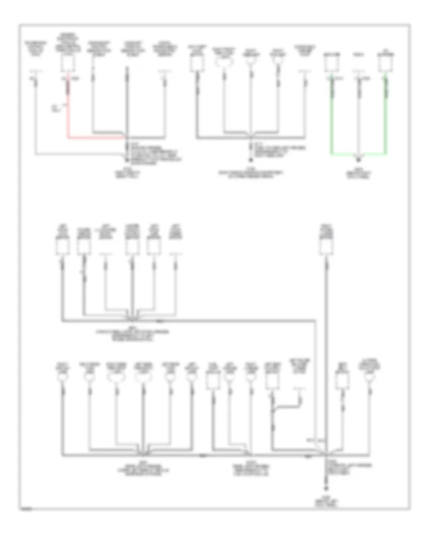
Ground Distribution Wiring Diagram (2 of 2) for Ford Ranger Splash 1997
 https://portal-diagnostov.com/license.html
Automotive Electricians Portal FZCO
Automotive Electricians Portal FZCO
https://portal-diagnostov.com/license.html
https://portal-diagnostov.com/license.html
Automotive Electricians Portal FZCO
Automotive Electricians Portal FZCOList of elements for Ground Distribution Wiring Diagram (2 of 2) for Ford Ranger Splash 1997:
- Amplifier
- Anti-theft hood switch
- C223
- Camshaft position sensor (cmp) shield
- Cd changer
- Crankshaft position sensor (ckp) shield
- Digital transmission range (dtr) sensor
- Fuel pump module
- G105 (right side of engine compartment, on upper fender apron)
- G123 (right side of safety wall)
- G200 (behind left cowl panel)
- G203 (behind right cowl panel)
- Generic electronic module (gem)/central timer module (ctm)
- Left backup lamp
- Left door ajar switch
- Left door disarm switch
- Left door lock switch
- Left illuminated entry switch
- Left license lamp
- Left power bolster lumbar motor
- Left rear park/stop lamp
- Left rear turn lamp
- Left seat control switch
- M/t only
- Master window control switch
- Outside cargo/high mount stop lamp
- Power mirror switch
- Powertrain control module (pcm)
- Radio
- Right backup lamp
- Right fog lamp
- Right front park/turn lamp
- Right headlamp
- Right license lamp
- Right power lumbar motor
- Right rear park/stop lamp
- Right rear turn lamp
- S1005 (rear lamp harness, near breakout to fuel pump module)
- S107 (engine harness, 2.3l & 4.0l: near breakout to ground 123; 3.0l: near breakout to octane adjust shorting bar)
- S117 (dash to headlamp harness, near breakout to right headlamp)
- S300 (interior lamp harness, below left front seat)
- S400 (rear lamp harness, under left rear of vehicle, near rear of frame)
- S500 (window regulator left door harness, near breakout to left power mirror switch)
- Seat belt switch
- Windshield washer pump
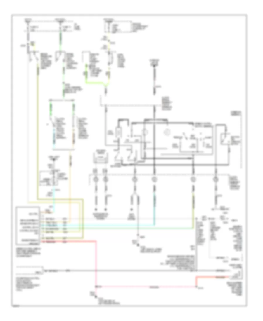
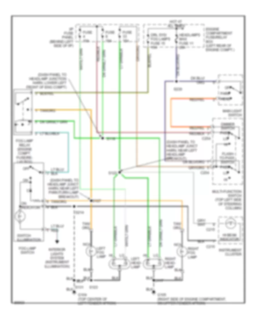
HEADLIGHTS
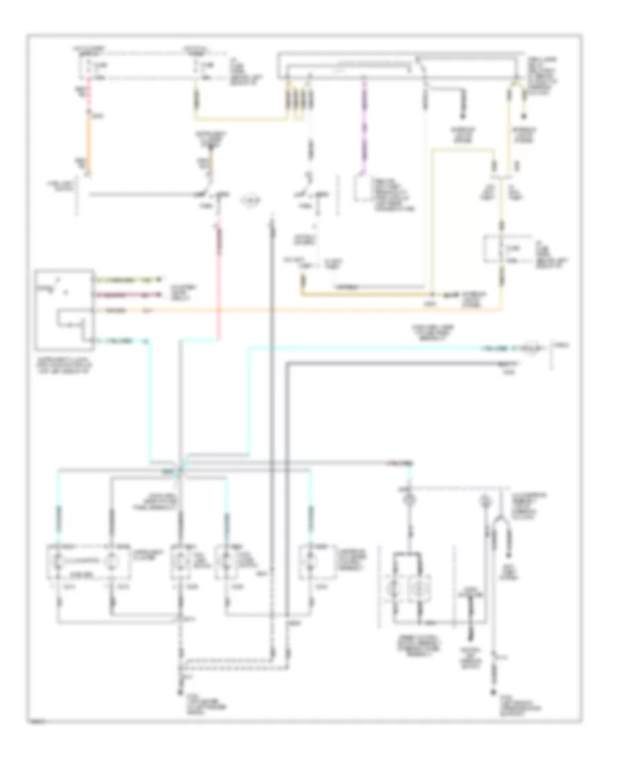
Headlight Wiring Diagram, with DRL for Ford Ranger Splash 1997
 https://portal-diagnostov.com/license.html
Automotive Electricians Portal FZCO
Automotive Electricians Portal FZCO
https://portal-diagnostov.com/license.html
https://portal-diagnostov.com/license.html
Automotive Electricians Portal FZCO
Automotive Electricians Portal FZCOList of elements for Headlight Wiring Diagram, with DRL for Ford Ranger Splash 1997:
- (dash panel to headlamp junct harn, near drl module breakout)
- (dash panel to headlamp junct harn, near left headlamp breakout)
- (dash panel to headlamp junct harn, near left park/turn lamp breakout)
- (dash panel to headlamp junction harn, in eng compt fuse/relay box breakout)
- (dash panel to headlamp junction harn, lower left front of eng compt)
- A/t
- Acc
- Back-up lamp switch (top left side of transmission)
- Battery pwr in
- Brake fluid level switch (on brake fluid reservoir)
- Brake indicator
- C215
- C216
- C254
- Daytime running lamps (drl) module (left side of lower radiator support)
- Digital transmission range (dtr) sensor (left side of transmission)
- Dimmer switch
- Drl disable
- Drl sys/ fog lamps fuse 15 15a
- Engine compartment fuse/relay box (left rear of engine compt)
- Flash- to-pass switch
- Fog lamp relay (engine compt. fuse/re- lay box)
- Fog lamp switch
- Fuse 10a
- Fuse 15a
- Fuse 7.5a
- G104 (top center of left fender apron)
- G105 (right side of engine compartment, on upper fender apron)
- Gnd
- Head
- Headlamps maxi fuse 11 20a
- Hi beam indicator
- Hi beam indicator out
- Hot at all times
- Hot in run
- Hot in start or run
- I/p fuse panel (behind left side of i/p)
- Ignition in
- Ignition switch
- Instrument cluster
- Interior lights system (instrument illumination)
- Left fog lamp
- Left head- lamp
- Lo beam in
- Lock
- M/t
- Main light switch
- Multi-function switch (top left side of steering column)
- Nca
- Off
- On indicator
- Park
- Park brake in
- Park brake switch (on park brake assembly)
- Pass
- Pulsed voltage to hi beams
- Rabs diode
- Rabs resistor
- Rear anti-lock brake system (rabs) module (behind lower center of i/p, left side of ashtray assembly)
- Right fog lamp
- Right head- lamp
- Run
- S117
- S119
- S120
- S122
- S123
- S126
- S127
- S150
- S214
- S230
- S240
- S244
- Start
- Switch illumination
- W/ 4wabs
- W/ rabs
- W/ rabs only
Headlight Wiring Diagram, without DRL for Ford Ranger Splash 1997
 https://portal-diagnostov.com/license.html
Automotive Electricians Portal FZCO
Automotive Electricians Portal FZCO
https://portal-diagnostov.com/license.html
https://portal-diagnostov.com/license.html
Automotive Electricians Portal FZCO
Automotive Electricians Portal FZCOList of elements for Headlight Wiring Diagram, without DRL for Ford Ranger Splash 1997:
- (dash panel to headlamp junct harn, near left headlamp breakout)
- (dash panel to headlamp junct harn, near left park/turn lamp breakout)
- (dash panel to headlamp junction harn, lower left front of eng compt)
- C215
- C254
- Dimmer switch
- Drl sys/ fog lamps fuse 15 15a
- Engine compartment fuse/relay box (left rear of engine compt.)
- Flash- to-pass switch
- Fog lamp relay (engine compt. fuse/re- lay box)
- Fog lamp switch
- Fuse 10a
- Fuse 15a
- G104 (top center of left fender apron)
- G105 (right side of engine compartment, on upper fender apron)
- Head
- Headlamps maxi fuse 11 20a
- Hi beam indicator
- Hot at all times
- I/p fuse panel (behind left side of i/p)
- Instrument cluster
- Interior lights system (instrument illumination)
- Left fog lamp
- Left head- lamp
- Main light switch
- Multi-function switch (top left side of steering column)
- Nca
- Off
- On indicator
- Park
- Pass
- Right fog lamp
- Right head- lamp
- S119
- S122
- S123
- S127
- S214
- S230
- Switch illumination
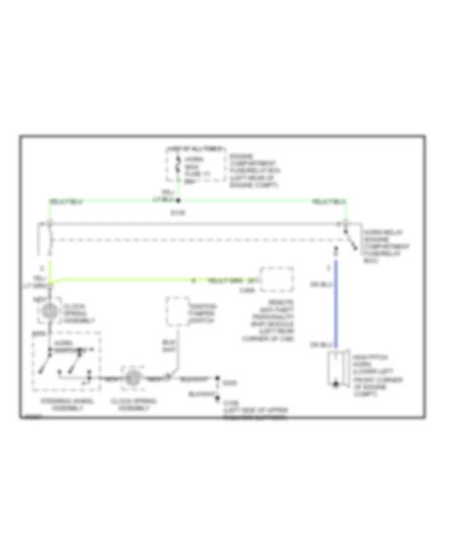
HORN
Horn Wiring Diagram for Ford Ranger Splash 1997
 https://portal-diagnostov.com/license.html
Automotive Electricians Portal FZCO
Automotive Electricians Portal FZCO
https://portal-diagnostov.com/license.html
https://portal-diagnostov.com/license.html
Automotive Electricians Portal FZCO
Automotive Electricians Portal FZCOList of elements for Horn Wiring Diagram for Ford Ranger Splash 1997:
- C409
- Clock spring assembly
- Clock- spring assembly
- Engine compartment fuse/relay box (left rear of engine compt)
- Front corner of engine compt)
- G108 (left side of upper radiator support)
- High pitch horn (lower left
- Horn maxi fuse 11 20a
- Horn relay (engine compartment fuse/relay box)
- Horn switches
- Hot at all times
- Ignition tamper switch
- Nca
- Remote anti-theft personality (rap) module (left rear corner of cab)
- S135
- S205
- Steering wheel assembly
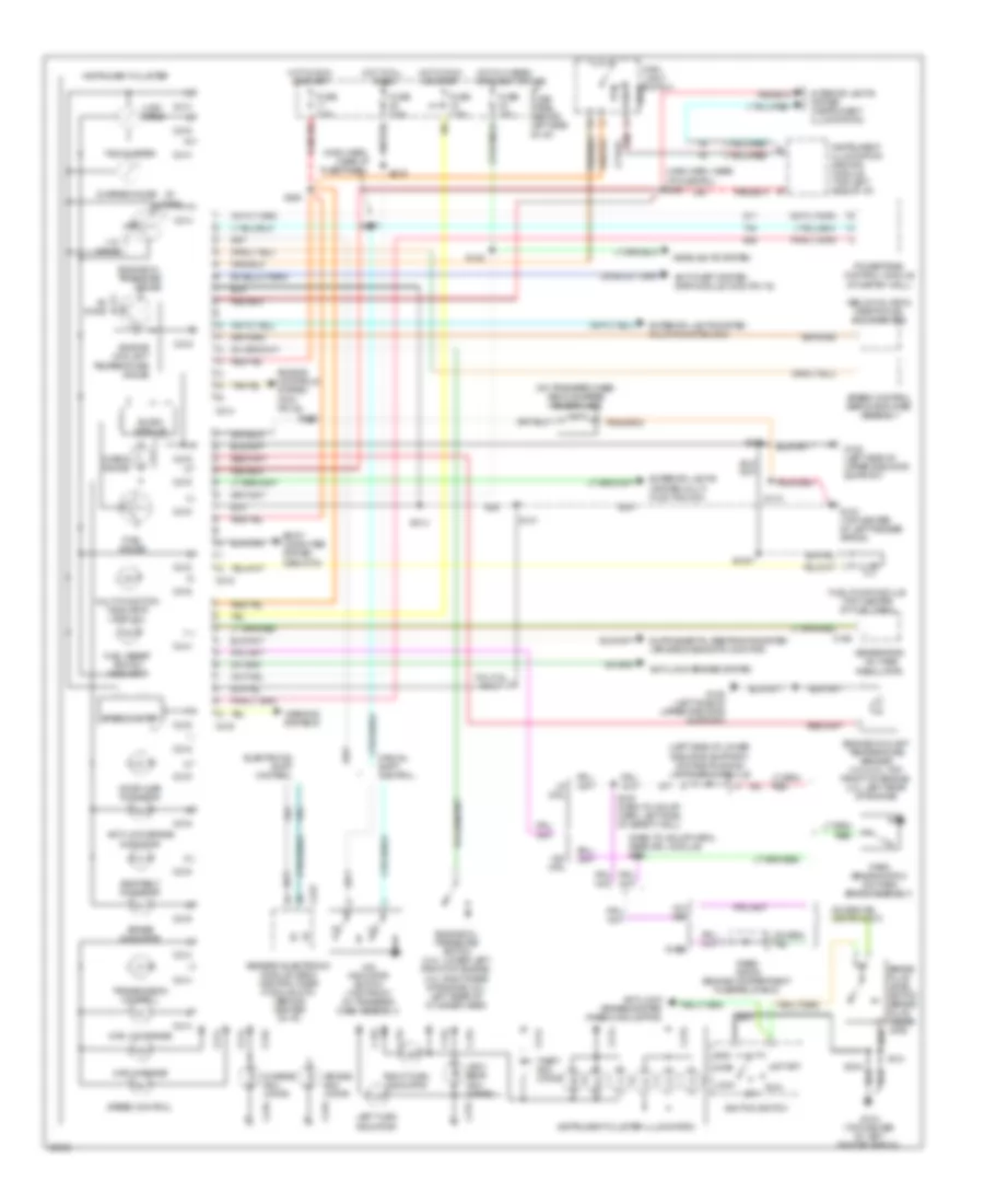
INSTRUMENT CLUSTER
Instrument Cluster Wiring Diagram for Ford Ranger Splash 1997
 https://portal-diagnostov.com/license.html
Automotive Electricians Portal FZCO
Automotive Electricians Portal FZCO
https://portal-diagnostov.com/license.html
https://portal-diagnostov.com/license.html
Automotive Electricians Portal FZCO
Automotive Electricians Portal FZCOList of elements for Instrument Cluster Wiring Diagram for Ford Ranger Splash 1997:
- (below glv box) inertia fuel shut-off (ifs)
- (dash to hdlmp harn, near drl module) s120
- (left side of lower radiator support) daytime running lamps (drl) module
- (main harn, near i/p fuse panel)
- (main harn, near i/p fuse pnl) s208
- (on transfer case) vehicle speed sensor (vss)
- 3.0l/4.0l only
- 4.32k ohms
- 4w- abs
- 4wd hi range
- 4wd low range
- 4x4 indicator switch (top front of transfer case assembly)
- Acc
- Air bag indi- cator
- Anti-lock brake indicator
- Anti-lock brakes system
- Anti-lock brakes system (rabs module pin2)
- Anti-theft system (rap module c409, pin 16)
- Body computer system (gem/ctm)
- Brake fluid level switch (brake fluid reser- voir)
- Brake indicator
- C168
- C214
- C215
- C216
- C223
- Charge gauge
- Charge indi- cator
- Check gauge
- Door ajar indicator
- Electronic shift control
- Engine controls system (pcm pin 48)
- Engine coolant temperature gauge
- Engine coolant temperature sender (3.0l/4.0l: top front of engine; 2.3l: left rear of engine)
- Engine oil pressure gauge
- Engine oil pressure switch (4.0l: lower left front of engine; 3.0l: right rear of engine; 2.3l: left rear of cylinder head)
- Exterior lights (system multi- function sw)
- Exterior lights system multi-function sw)
- Fuel gauge
- Fuel pump module (top center of fuel tank)
- Fuel reset switch indicator
- Fuse 15a
- Fuse 7.5a
- G104 (top center of left fender apron)
- G108 (left side of upper radiator support)
- Generator/ voltage regulator
- Generic electronic module (gem)/ central timer module (ctm) (behind center of i/p)
- Gnd
- Head
- Headlights system
- High beam indi- cator
- Hot at all times
- Hot in hi beam or flash to pass
- Hot in run or start
- I/p fuse panel (behind left side of i/p)
- Ignition switch
- Instrument cluster
- Instrument cluster illumination
- Instrument illumination dimming module (top left side of i/p)
- Interior lights system (instrument illumination)
- Left turn indicator
- Lock
- Main light switch
- Manual shift control
- Multi-function indicator lamp (mil)
- Off
- Ohms
- Park
- Park brake switch (on park brake assembly)
- Powertrain control module (at saftey wall)
- Rabs
- Rabs diode (engine compartment fuse/relay box)
- Red
- Right turn indicator
- Run
- S1007
- S110
- S120 (dash to hdlmp harn, left side of safety wall)
- S122
- S131
- S205
- S214
- S219
- S229
- S237
- S240
- S244
- Seat belt indicator
- Slosh module
- Speed control
- Speed control servo/amplifier assembly
- Speedometer
- Start
- Tachometer
- Theft indi- cator
- Transmission control
- W/ drl
- W/o drl
- Warning systems
INTERIOR LIGHTS
Courtesy Lamps Wiring Diagram for Ford Ranger Splash 1997
 https://portal-diagnostov.com/license.html
Automotive Electricians Portal FZCO
Automotive Electricians Portal FZCO
https://portal-diagnostov.com/license.html
https://portal-diagnostov.com/license.html
Automotive Electricians Portal FZCO
Automotive Electricians Portal FZCOList of elements for Courtesy Lamps Wiring Diagram for Ford Ranger Splash 1997:
- (main harn, center of i/p near breakout to rear abs module) s206
- Battery saver relay
- Battery saver relay control
- C221
- C224
- Dome
- Dome lamp
- Dome/ map lamp
- Engine compartment fuse/relay box (left rear of engine compartment)
- Except xl model
- Exterior lights system
- Fuse 10a
- G104 (top center of left fender apron)
- G200 (behind left cowl panel)
- Generic electronic module (gem)/ central timer module (ctm) (behind center of i/p)
- Glove box lamp and switch
- High mount stop lamp
- Hot at all times
- I/p fuse panel (behind left side of i/p)
- Illuminated entry input
- Instrument illumination dimming module (top left side of i/p)
- Interior lamp relay
- Interior lamp relay control
- Left door ajar switch
- Left door ajar switch input
- Left illuminated entry switch
- Outside cargo lamp
- Outside cargo/ high mount stop lamp
- Park lamps maxi fuse 8 20a
- Pnk
- Relay box #1 (behind i/p, right of steering column)
- Right door ajar switch
- Right door ajar switch input
- Right illuminated entry switch
- S221
- S224
- S300
- S500
- S600
- Xl model
Instrument Illumination Wiring Diagram for Ford Ranger Splash 1997
 https://portal-diagnostov.com/license.html
Automotive Electricians Portal FZCO
Automotive Electricians Portal FZCO
https://portal-diagnostov.com/license.html
https://portal-diagnostov.com/license.html
Automotive Electricians Portal FZCO
Automotive Electricians Portal FZCOList of elements for Instrument Illumination Wiring Diagram for Ford Ranger Splash 1997:
- (6 bulbs)
- (main harn, near i/p fuse panel breakout)
- 15a
- 4wd mode switch
- 7.5a
- Anti- theft system
- C201
- C214
- C215
- C225
- C228
- C233
- C236
- Clockspring assembly (top of steering column)
- Courtesy lamps circuit
- Dome
- Exterior lights system
- Fog lamp switch
- Fuse
- G104 (top center of left fender apron)
- G108 (left side of upper radiator support)
- Head
- Heater or a/c-heater control assembly
- Horn switches
- Hot at all times
- Hot in start or run
- I/p fuse panel (behind left side of i/p)
- Ignition key warning switch
- Illumination
- Instrument cluster
- Instrument cluster system
- Instrument illumin- ation dimming module (top left side of i/p)
- Main light switch
- Nca
- Off
- Park
- Radio
- Remote anti-theft personality (rap) module (left rear corner of cab)
- S118
- S131
- S208
- S209
- S214
- S234
- S240
- S244
- Speed control switch assembly (steering wheel assembly)
- Theft
- W/ anti- theft
- W/o anti-
- W/o anti- theft
POWER DISTRIBUTION
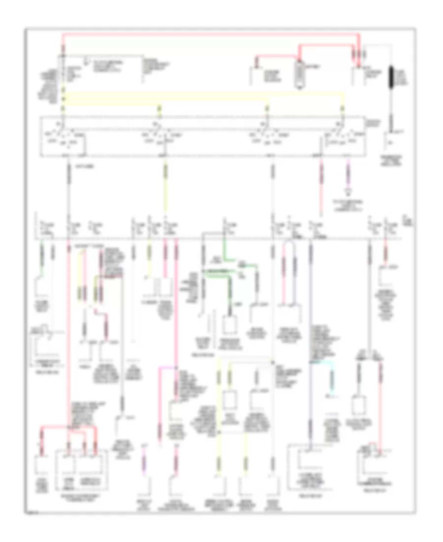
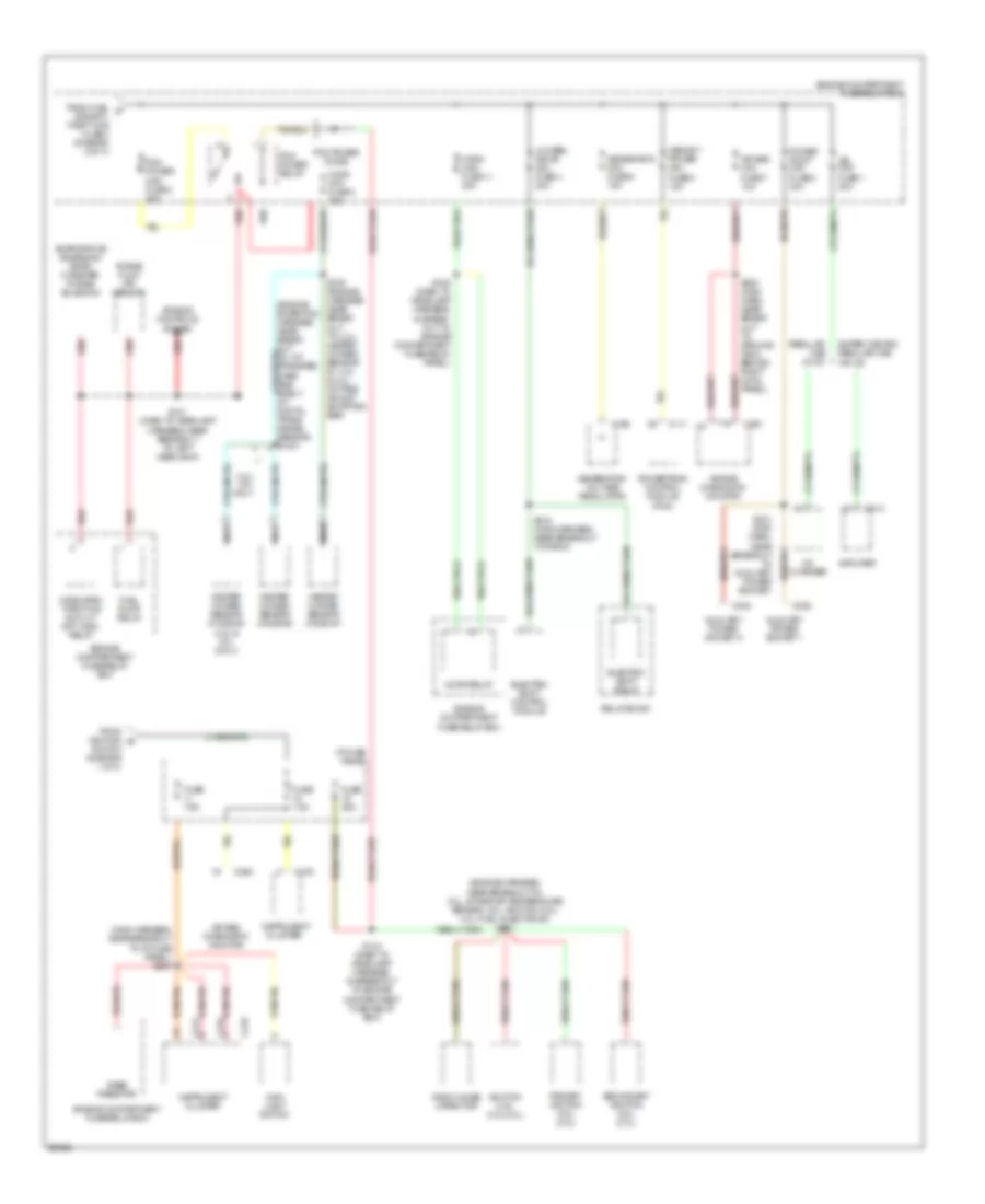
Power Distribution Wiring Diagram (1 of 3) for Ford Ranger Splash 1997
 https://portal-diagnostov.com/license.html
Automotive Electricians Portal FZCO
Automotive Electricians Portal FZCO
https://portal-diagnostov.com/license.html
https://portal-diagnostov.com/license.html
Automotive Electricians Portal FZCO
Automotive Electricians Portal FZCOList of elements for Power Distribution Wiring Diagram (1 of 3) for Ford Ranger Splash 1997:
- (dash to headlamp harness, near break- out to engine compt fuse/ relay box) s136
- (dash to headlamp harness, near breakout to c135 & c136, left side of safety wall) s138
- (dash to headlamp harness, near breakout to ground g104, top center of left fender apron) s124
- (engine extention harn, near breakout to c114, left rear of engine) s1002
- (main harness, in break- out to ignition switch & shift lock actuator) s232
- (not used)
- 4 wheel anti- lock brake system (4wabs) main relay
- 4 wheel anti-lock brake system (4wabs) module
- A/c- heater control assembly
- A/t
- Acc
- Air bag diagnostic monitor
- Back-up lamp switch
- Battery
- Blend door actuator
- Blower motor relay
- Brake pressure switch
- C177
- C178
- C224
- C228
- C251
- C256
- C410
- Clutch pedal position (ccp) switch
- Daytime runing lamps (drl) module
- Digital transmission range (dtr) sensor
- Engine compartment fuse/relay box
- Flasher
- Fuse 10a
- Fuse 10a (4wabs)
- Fuse 15a
- Fuse 20a (rabs)
- Fuse 30a
- Fuse 7.5a
- Generator/ voltage regulator
- Generic electronic module (gem)/ central timer module (ctm)
- I/p fuse panel
- Ignition maxi fuse 14 50a
- Ignition switch
- Lock
- M/t
- Nca
- Off
- Passive de- activation (pad) module
- Power window relay
- Radio
- Rear anti- lock brake system (rabs) module
- Red
- Relay box #1
- Relay box #2
- Relay box #3
- Remote anti-theft personality (rap) module
- Run
- S126 (dash to headlamp harness, near breakout to left front park/turn lamp)
- S227 (main harness, near break- out to instrument cluster)
- S250 (main harness, near breakout to i/p fuse panel)
- Shift lock actuator
- Speed control servo/amplifier assembly
- Sta
- Start
- Starter interrupt relay
- Starter motor/ solenoid
- Starter relay
- To i/p fuse panel, fuse 15 (diagram 3 of 3)
- To i/p fuse/panel maxi fuse 13 (diagram 2 of 3)
- Trans- mission control switch (tcs)
- W/ anti- theft
- W/ pad
- W/o anti- theft
- W/o pad
- W/o rap w/ rap
- Washer pump relay
- Wind- shield wiper motor
- Wiper hi-lo relay
- Wiper run/ park relay
Power Distribution Wiring Diagram (2 of 3) for Ford Ranger Splash 1997
 https://portal-diagnostov.com/license.html
Automotive Electricians Portal FZCO
Automotive Electricians Portal FZCO
https://portal-diagnostov.com/license.html
https://portal-diagnostov.com/license.html
Automotive Electricians Portal FZCO
Automotive Electricians Portal FZCOList of elements for Power Distribution Wiring Diagram (2 of 3) for Ford Ranger Splash 1997:
- (main harness, near break- out to ignition tamper switch & clockspring assembly) s224
- (main harness, near breakout to ignition tamper switch & clockspring assembly) s222
- (main harness, near breakout to instrument cluster) s221
- 4wabs main relay
- 4wabs main relay maxi fuse 6 30a
- 4wabs pump motor relay
- 4wabs pump relay maxi fuse 5 30a
- All lock relay
- All unlock relay
- Amplifier
- Battery saver relay
- Blower motor maxi fuse 9 40a
- Blower motor relay
- Brake on/off (boo) switch
- C216
- C224
- C228
- C254
- C409
- C414
- Cd changer
- Cigar lighter
- Data link connector (dlc)
- Daytime running lamps (drl) module
- Dimmer switch
- Dome/ map light
- Driver's unlock relay
- Drl sys/fog lamps mini fuse 8 15a
- Electric shift control module
- Electric shift relay
- Engine compartment fuse/relay box
- Exterior lights system (main light switch or park lamps relay)
- Flash- to-pass switch
- Flasher
- Fog lamp relay
- From a
- Fuel pump relay
- Fuel sys/ anti-theft maxi fuse 3 20a
- Fuse (not used)
- Fuse 10a
- Fuse 15a
- Fuse 25a
- Fuse 7.5a
- G104 (top center of left fender apron)
- Generic electronic module (gem)/ central timer module (ctm)
- Glove box lamp & switch
- Harness near break- out to i/p fuse panel) s223
- Head
- Head- lamps maxi fuse 4 20a
- Headlights system
- I/p fuse panal maxi fuse 13 50a
- I/p fuse panel
- Ignition maxi fuse 14 (diagram 1 of 3)
- Instrument cluster
- Instrument illumination dimming module
- Interior lamp relay
- Left power bolster switch
- Left power lumbar switch
- Left seat control switch
- Main light switch
- Multi- function switch
- Nca
- Off
- Park
- Park lamps maxi fuse 8 20a
- Park lamps relay
- Pas
- Pnk
- Power lock/ window/seat maxi fuse 10 20a
- Power mirror switch
- Power window relay
- Rabs test connector
- Radio
- Red
- Regular cab w/ cd
- Relay box #1
- Relay box #2
- Relay box #3
- Remote anti- theft personality (rap) module
- Right power lumbar switch
- S209
- S219 (main harn, near breakout to radio)
- S302 (interior lamp harness, near breakout to right rear speaker)
- Super cab
- Super cab only
- To pcm power maxi fuse 2 (diagram 3 of 3)
- W/ premium sound
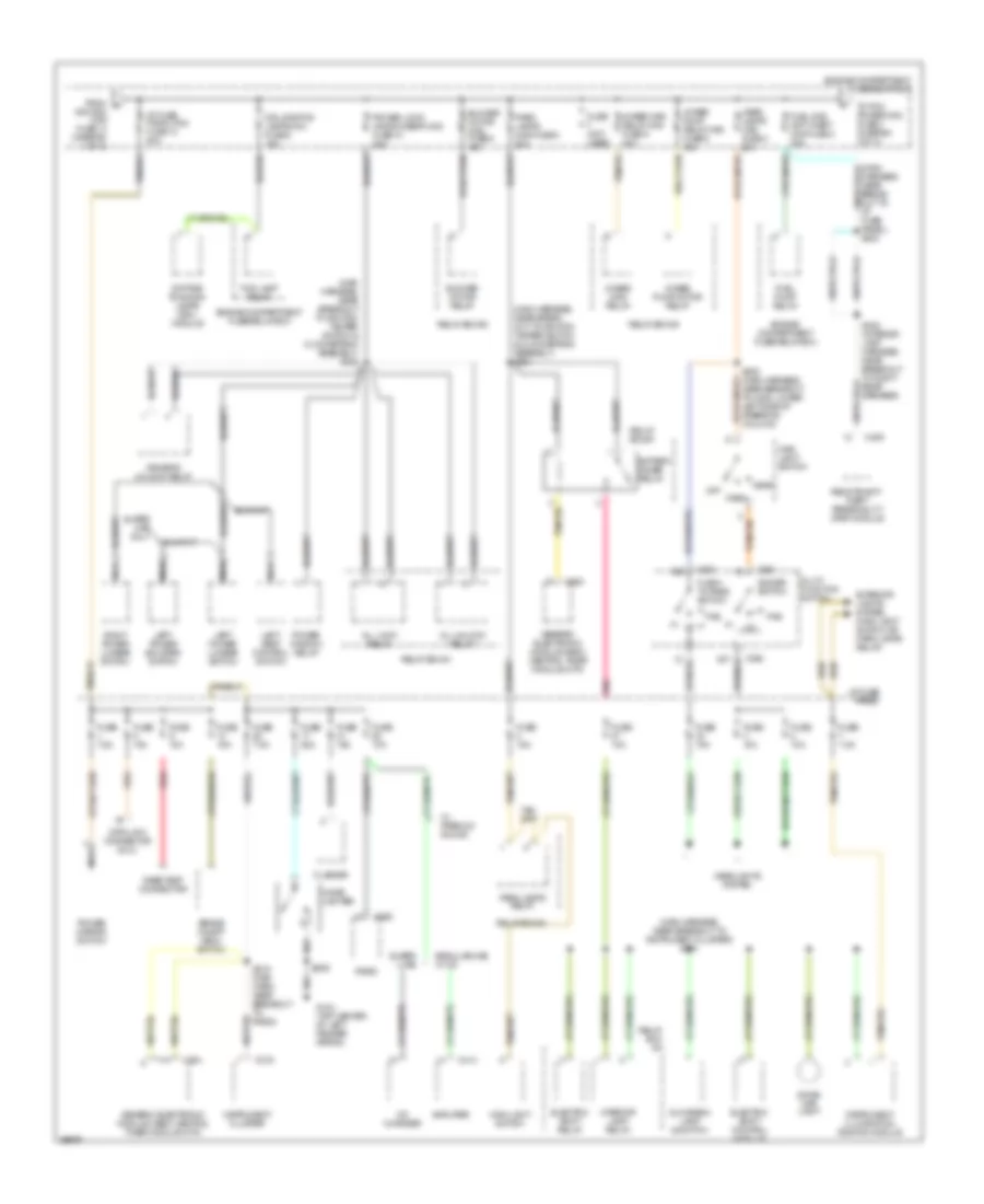
Power Distribution Wiring Diagram (3 of 3) for Ford Ranger Splash 1997
 https://portal-diagnostov.com/license.html
Automotive Electricians Portal FZCO
Automotive Electricians Portal FZCO
https://portal-diagnostov.com/license.html
https://portal-diagnostov.com/license.html
Automotive Electricians Portal FZCO
Automotive Electricians Portal FZCOList of elements for Power Distribution Wiring Diagram (3 of 3) for Ford Ranger Splash 1997:
- (engine harness, near breakout to: 2.3l, intake air temperature sensor; 3.0l, ignition coil; 4.0l, fuel injector #3) s101
- (main harness, near breakout to i/p fuse panel) s240
- 3.0l/ 4.0l only
- 4 wheel drive mini fuse 4 20a
- Air bag diagnostic monitor
- Air bag mini fuse 7 10a
- Amplifier
- Auxiliary power socket 1
- Auxiliary power socket 2
- C111
- C168
- C214
- C215
- C216
- C235
- C248
- C250
- C251
- C414
- Cd changer
- Cluster
- Electric shift control module
- Electric shift relay
- Engine compartment fuse/relay box
- Engine controls system
- Evaporative emissions (evap) canister purge solenoid
- From fuel c sys/anti- theft maxi fuse 3 (diagram 2 of 3)
- From ignition b
- Fuel pump relay
- Fuse 25a
- Fuse 7.5a
- Generator mini fuse 6 15a
- Generator/ voltage regulator
- Heated oxygen sensor (ho2s) #1
- Heated oxygen sensor (ho2s) #2
- Heated oxygen sensor (ho2s) #3 (4.0l & 3.0l only)
- Ho2s mini fuse 3 15a
- Horn maxi fuse 11 20a
- Horn relay
- I/p fuse panel
- Ignition coil (3.0l/4.0l)
- Instrument
- Instrument cluster
- Jbl mini fuse 1 20a
- Main light switch
- Memory power mini fuse 5 15a
- Nca
- Pcm power diode
- Pcm power maxi fuse 2 30a
- Pcm power relay
- Power point mini fuse 2 30a
- Powertrain control module (pcm)
- Primary ignition coil (2.3l)
- Purge flow (pf) sensor
- Rabs resistor
- Radio noise capacitor
- Red
- Regular cab w/ cd
- Relay box #1
- S109 (engine harness near break- out to: 2.3l, heated oxygen sensor #1; 4.0l & 3.0l, octane adjust shorting bar)
- S121 (dash to headlamp harness, near breakout to left headlamp)
- S134 (dash to headlamp harness, in breakout to engine compartment fuse relay box)
- S135 (dash to headlamp harness, in break- out to engine compartment fuse/relay panel)
- S200 (main harn, near break- out to ground g203, behind right cowl panel)
- S218 (main harness, near breakout to radio)
- S231 (main harn, near breakout to auxiliary power socket)
- Secondary ignition coil (2.3l)
- Super cab and regular cab w/o cd
- Switch (diagram 1 of 3)
- Wide open throttle a/c cut- off (wac) relay
POWER DOOR LOCKS
Power Door Lock Wiring Diagram for Ford Ranger Splash 1997
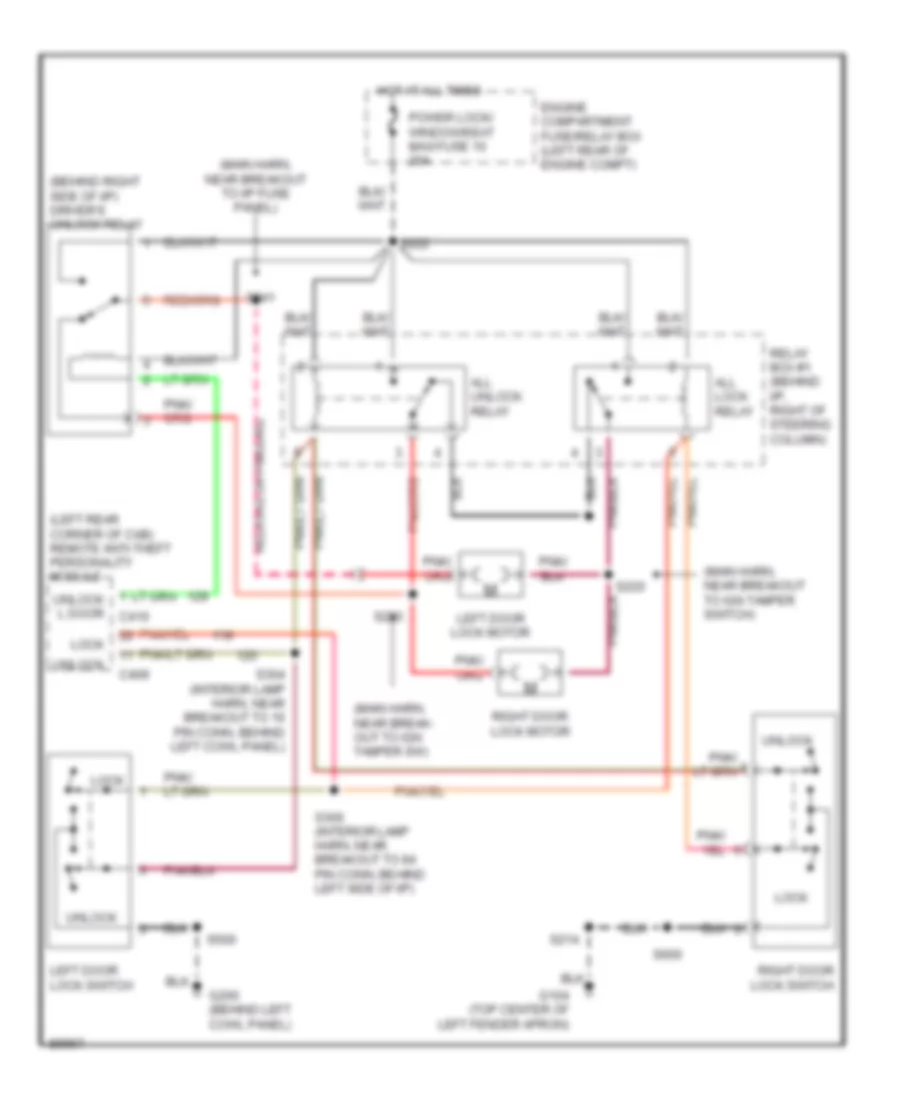 https://portal-diagnostov.com/license.html
Automotive Electricians Portal FZCO
Automotive Electricians Portal FZCO
https://portal-diagnostov.com/license.html
https://portal-diagnostov.com/license.html
Automotive Electricians Portal FZCO
Automotive Electricians Portal FZCOList of elements for Power Door Lock Wiring Diagram for Ford Ranger Splash 1997:
- (behind right side of i/p) driver's unlock relay
- (left rear corner of cab) remote anti-theft personality module
- (main harn, near break- out to ign tamper sw)
- (main harn, near breakout to i/p fuse panel)
- (main harn, near breakout to ign tamper switch)
- All lock relay
- All unlock relay
- C409
- Engine compartment fuse/relay box (left rear of engine compt)
- G104 (top center of left fender apron)
- G200 (behind left cowl panel)
- Hot at all times
- Left door lock motor
- Left door lock switch
- Lock
- Power lock/ window/seat maxi fuse 10 20a
- Relay box #1 (behind i/p, right of steering column)
- Right door lock motor
- Right door lock switch
- S214
- S220
- S222
- S223
- S241
- S304 (interior lamp harn, near breakout to 16 pin conn, behind left cowl panel)
- S306 (interior lamp harn, near breakout to 84 pin conn, behind left side of i/p)
- S500
- S600
- Unlock
- Unlock l door c410
POWER MIRRORS
Power Mirror Wiring Diagram for Ford Ranger Splash 1997
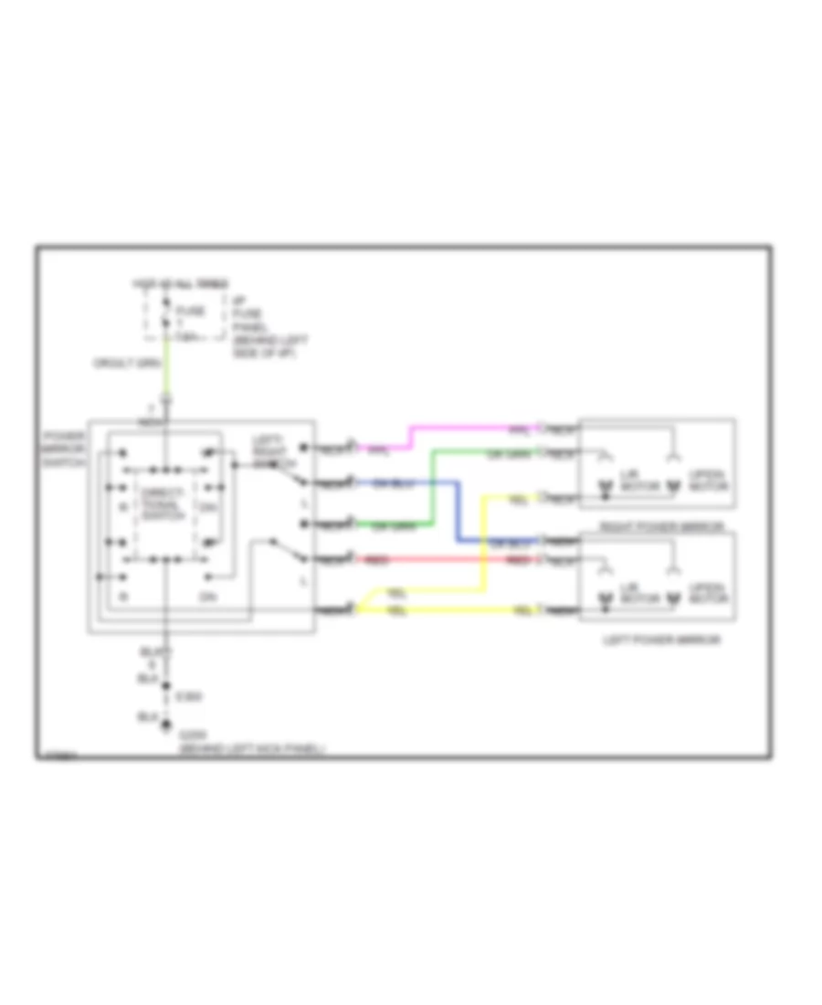 https://portal-diagnostov.com/license.html
Automotive Electricians Portal FZCO
Automotive Electricians Portal FZCO
https://portal-diagnostov.com/license.html
https://portal-diagnostov.com/license.html
Automotive Electricians Portal FZCO
Automotive Electricians Portal FZCOList of elements for Power Mirror Wiring Diagram for Ford Ranger Splash 1997:
- Direct- tional switch
- Fuse 7.5a
- G200 (behind left kick panel)
- Hot at all times
- I/p fuse panel (behind left side of i/p)
- L/r motor
- Left power mirror
- Left/ right switch
- Nca
- Power mirror switch
- Red
- Right power mirror
- S300
- Up/dn motor
POWER SEATS
Driver Power Seat Wiring Diagram for Ford Ranger Splash 1997
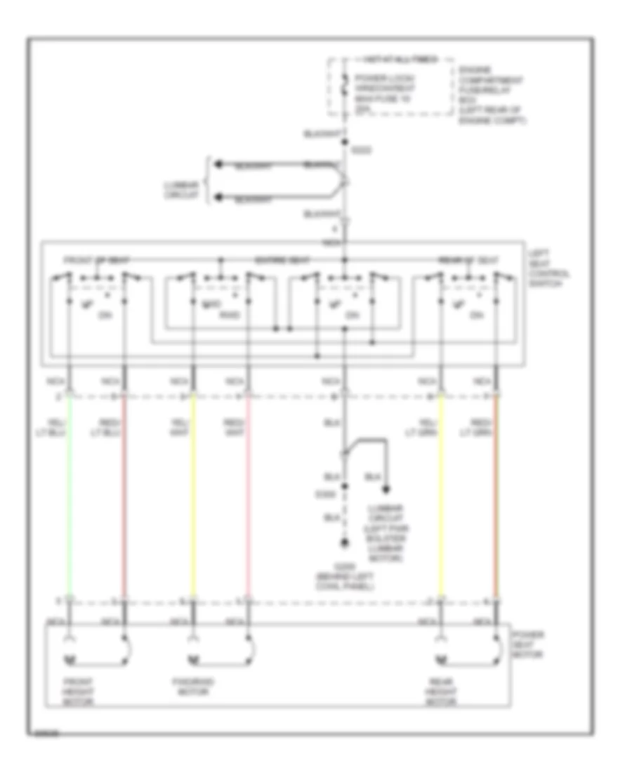 https://portal-diagnostov.com/license.html
Automotive Electricians Portal FZCO
Automotive Electricians Portal FZCO
https://portal-diagnostov.com/license.html
https://portal-diagnostov.com/license.html
Automotive Electricians Portal FZCO
Automotive Electricians Portal FZCOList of elements for Driver Power Seat Wiring Diagram for Ford Ranger Splash 1997:
- Engine compartment fuse/relay box (left rear of engine compt)
- Entire seat
- Front height motor
- Front of seat
- Fwd
- Fwd/rwd motor
- G200 (behind left cowl panel)
- Hot at all times
- Left seat control switch
- Lumbar circuit
- Lumbar circuit (left pwr bolster lumbar motor)
- Nca
- Power lock/ window/seat maxi fuse 10 20a
- Power seat motor
- Rear height motor
- Rear of seat
- Rwd
- S222
- S300
Lumbar Wiring Diagram for Ford Ranger Splash 1997
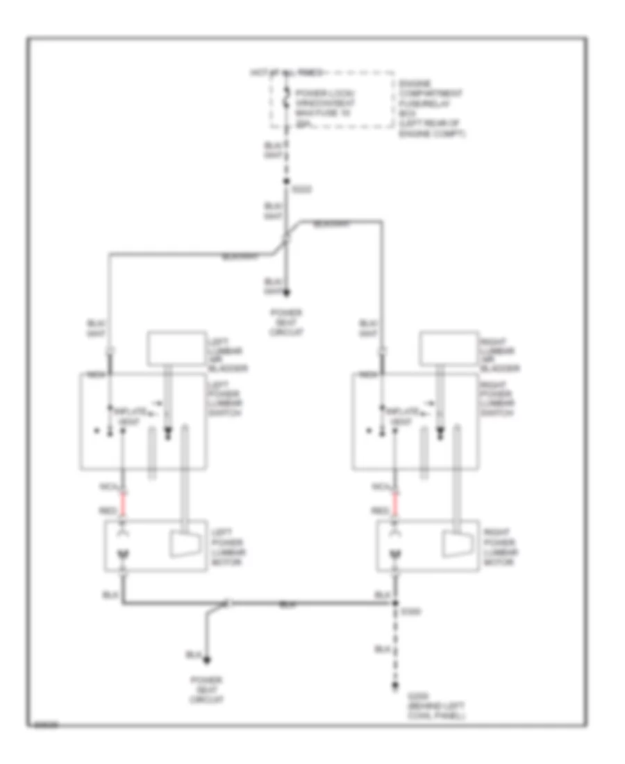 https://portal-diagnostov.com/license.html
Automotive Electricians Portal FZCO
Automotive Electricians Portal FZCO
https://portal-diagnostov.com/license.html
https://portal-diagnostov.com/license.html
Automotive Electricians Portal FZCO
Automotive Electricians Portal FZCOList of elements for Lumbar Wiring Diagram for Ford Ranger Splash 1997:
- Engine compartment fuse/relay box (left rear of engine compt)
- G200 (behind left cowl panel)
- Hot at all times
- Inflate
- Left lumbar air bladder
- Left power lumbar motor
- Left power lumbar switch
- Nca
- Power lock/ window/seat maxi fuse 10 20a
- Power seat circuit
- Red
- Right lumbar air bladder
- Right power lumbar motor
- Right power lumbar switch
- S222
- S300
- Vent
POWER WINDOWS
Power Window Wiring Diagram for Ford Ranger Splash 1997
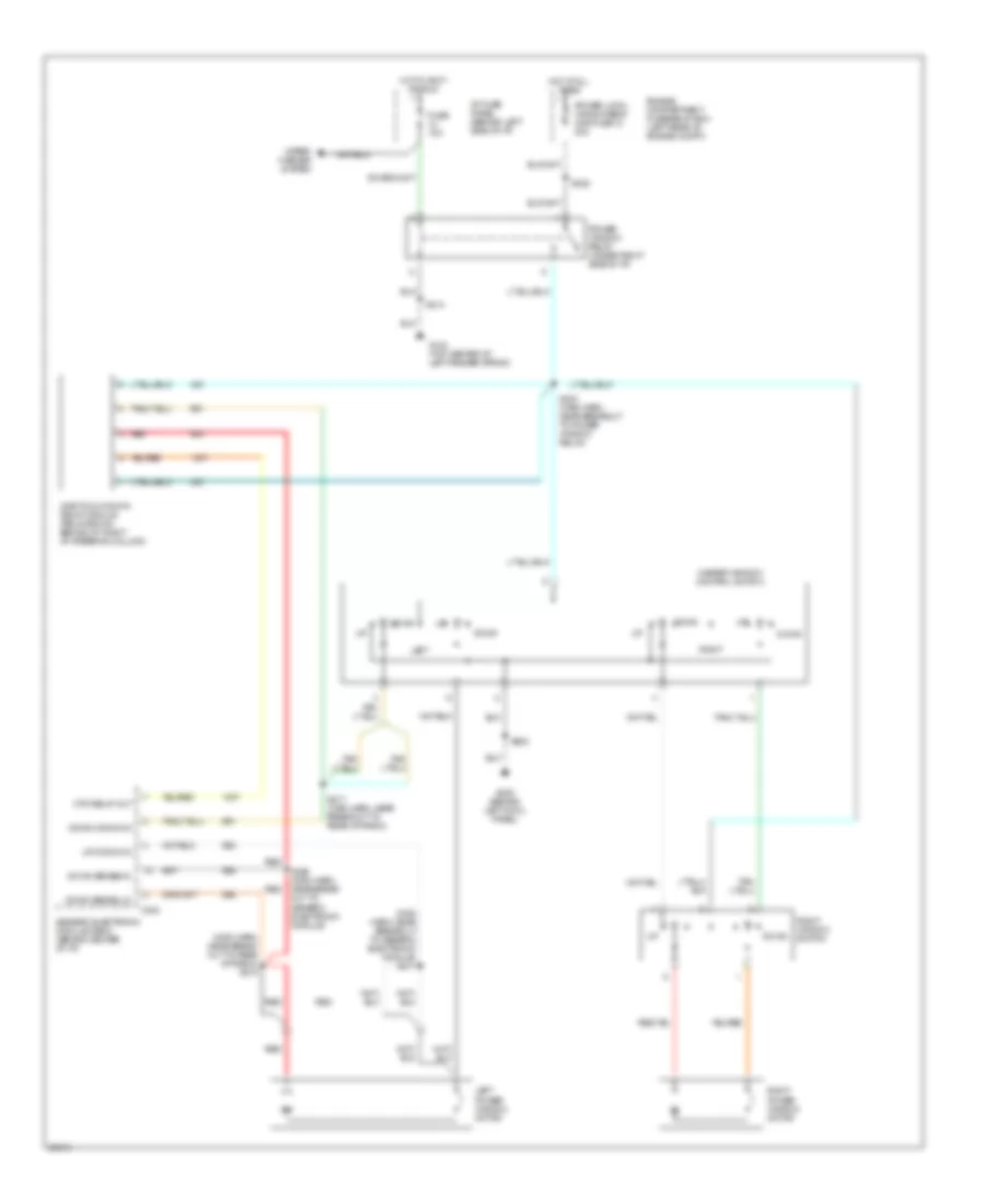 https://portal-diagnostov.com/license.html
Automotive Electricians Portal FZCO
Automotive Electricians Portal FZCO
https://portal-diagnostov.com/license.html
https://portal-diagnostov.com/license.html
Automotive Electricians Portal FZCO
Automotive Electricians Portal FZCOList of elements for Power Window Wiring Diagram for Ford Ranger Splash 1997:
- (main harn, near break- out to rear of radio) s210
- (main harn, near breakout to generic electronic module) s211
- C224
- Down
- Down comnd in
- Down sense(hi)
- Down sense(lo)
- Engine compartment fuse/relay box (left rear of engine compt)
- Fuse 10a
- G104 (top center of left fender apron)
- G200 (behind left cowl panel)
- Generic electronic module (gem)/ (behind center of i/p)
- Hot at all times
- Hot in accy or run
- I/p fuse panel (behind left side of i/p)
- Left
- Left power window motor
- Master window control switch
- One touch down relay module (relay box #1, behind i/p, right of steering column)
- Otd relay out
- Power lock/ window/seat maxi fuse 10 20a
- Power window relay (under right side of i/p)
- Red
- Right
- Right power window motor
- Right window switch
- S203 (main harn, near breakout to power window relay)
- S214
- S217 (main harn, near breakout to rear of radio)
- S222
- S226 (main harn, near break- out to generic electronic module)
- S500
- Up comnd in
- Wiper/ washer system
RADIO
Base Radio for Ford Ranger Splash 1997
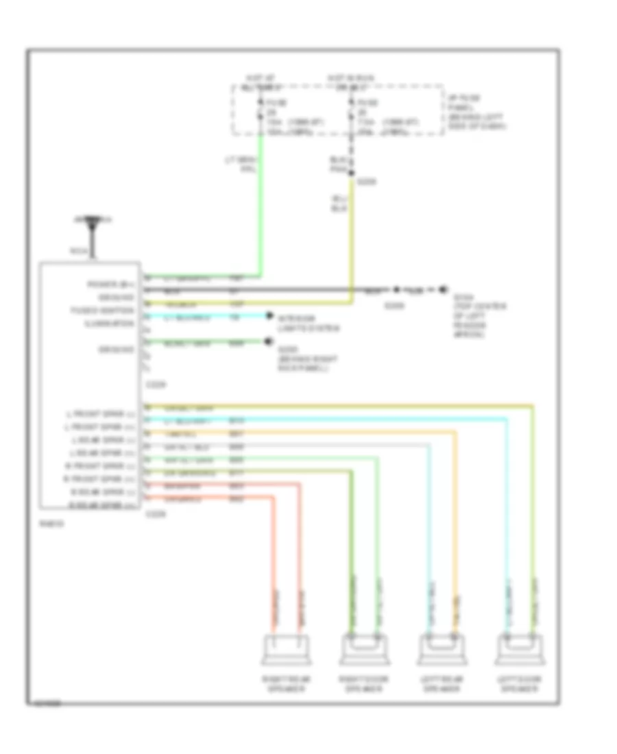 https://portal-diagnostov.com/license.html
Automotive Electricians Portal FZCO
Automotive Electricians Portal FZCO
https://portal-diagnostov.com/license.html
https://portal-diagnostov.com/license.html
Automotive Electricians Portal FZCO
Automotive Electricians Portal FZCOList of elements for Base Radio for Ford Ranger Splash 1997:
- (1996-97) (1995)
- Antenna
- C229
- Fuse 10a 15a
- Fuse 7.5a 10a
- Fused ignition
- G104 (top center of left fender apron)
- G203 (behind right kick panel)
- Ground
- Hot at all times
- Hot in run or acc
- I/p fuse panel (behind left side of dash)
- Ilumination
- Interior lights system
- L front spkr (+)
- L front spkr (-)
- L rear spkr (+)
- L rear spkr (-)
- Left door speaker
- Left rear speaker
- Nca
- Power (b+)
- R front spkr (+)
- R front spkr (-)
- R rear spkr (+)
- R rear spkr (-)
- Radio
- Right door speaker
- Right rear speaker
- S209
- S238
Premium Sound Radio Wiring Diagram for Ford Ranger Splash 1997
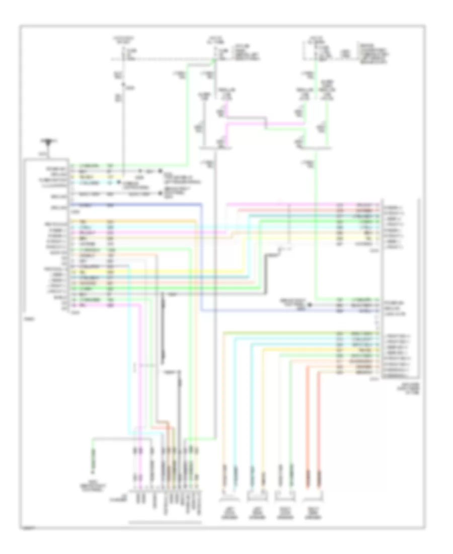 https://portal-diagnostov.com/license.html
Automotive Electricians Portal FZCO
Automotive Electricians Portal FZCO
https://portal-diagnostov.com/license.html
https://portal-diagnostov.com/license.html
Automotive Electricians Portal FZCO
Automotive Electricians Portal FZCOList of elements for Premium Sound Radio Wiring Diagram for Ford Ranger Splash 1997:
- (1997) (1998)
- (behind right kick panel) g203
- (benind right kick panel) g203
- Amplifier (right rear of cab)
- Antenna
- Audio on
- C228
- C243
- C414
- C415
- Cd changer
- Engine compartment fuse/relay box (left rear of engine compt)
- Fuse 1 (jbl) 22 (jbl) 20a
- Fuse 10a
- Fuse 7.5a
- Fused ignition
- G104 (top center of left fender apron)
- G203 (behind right kick panel)
- Ground
- Hot at all times
- Hot in run or acc
- I/p fuse panel (behind left side of dash)
- Illulminaton
- Interior lights system
- L front (+)
- L front (-)
- L front sig (+)
- L front sig (-)
- L rear (+)
- L rear (-)
- L rear sig (+)
- L rear sig (-)
- Left door speaker
- Left rear speaker
- Logic mute
- Nca
- Power (b+)
- Protocal b
- Protocol a
- Protocol b
- R front (+)
- R front (-)
- R front sig (+)
- R front sig (-)
- R rear (+)
- R rear (-)
- R rear sig (+)
- R rear sig (-)
- Radio
- Regular cab w/ cd
- Right door speaker
- Right rear speaker
- S209
- S228
- Shield
- Super cab
- Super cab & regular cab w/o cd
- Tan
SHIFT INTERLOCKS
Shift Interlock Wiring Diagram for Ford Ranger Splash 1997
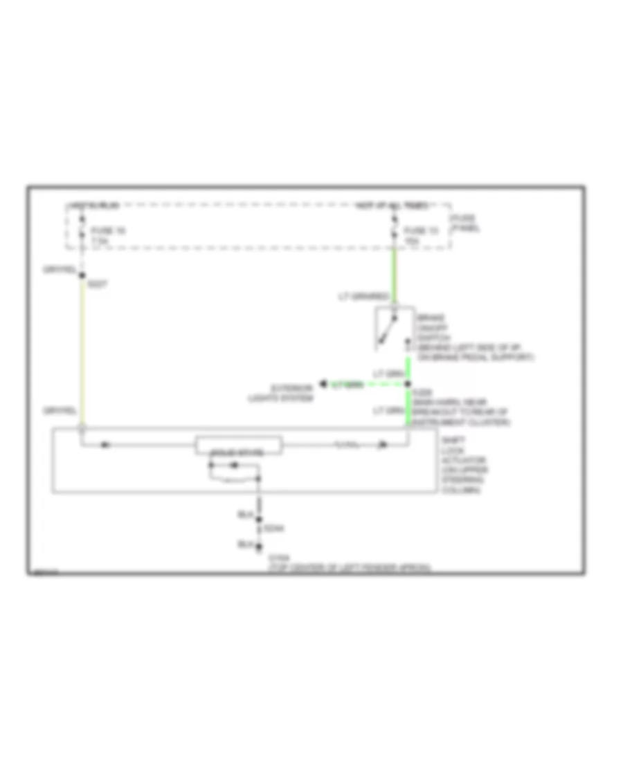 https://portal-diagnostov.com/license.html
Automotive Electricians Portal FZCO
Automotive Electricians Portal FZCO
https://portal-diagnostov.com/license.html
https://portal-diagnostov.com/license.html
Automotive Electricians Portal FZCO
Automotive Electricians Portal FZCOList of elements for Shift Interlock Wiring Diagram for Ford Ranger Splash 1997:
- Brake on/off switch (behind left side of i/p, on brake pedal support)
- Exterior lights system
- Fuse 10 7.5a
- Fuse 13 15a
- Fuse panel
- G104 (top center of left fender apron)
- Hot at all times
- Hot in run
- S227
- S228 (main harn, near breakout to rear of instrument cluster)
- S244
- Shift lock actuator (on upper steering column)
- Solid state
STARTING/CHARGING
Charging Wiring Diagram for Ford Ranger Splash 1997
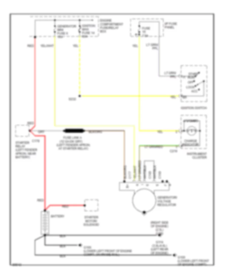 https://portal-diagnostov.com/license.html
Automotive Electricians Portal FZCO
Automotive Electricians Portal FZCO
https://portal-diagnostov.com/license.html
https://portal-diagnostov.com/license.html
Automotive Electricians Portal FZCO
Automotive Electricians Portal FZCOList of elements for Charging Wiring Diagram for Ford Ranger Splash 1997:
- (left fender apron,
- (right side of engine) (2.3l) g120
- 470 ohms
- Acc
- At starter relay)
- Battery
- C168
- C169
- C177
- C178
- C216
- Charge indicator
- Engine compartment fuse/relay box
- Fuse 7.5a
- Fuse link a
- G100 (lower left front of engine compt)
- G100 (lower left front of engine compt, on frame rail)
- G114 (3.0l/4.0l) (left rear of engine)
- Generator mini fuse 6 15a
- Generator/ voltage regulator
- I/p fuse panel
- Ignition maxi fuse 14 50a
- Ignition switch
- Instrument cluster
- Lock
- Off
- Red
- S232
- Start run
- Starter motor/ solenoid
- Starter relay (left fender apron, near battery)
Starting Wiring Diagram, A/T for Ford Ranger Splash 1997
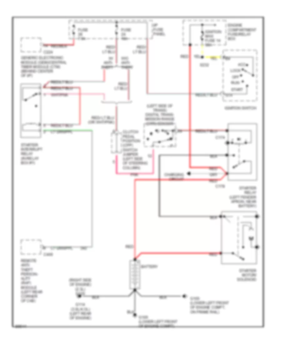 https://portal-diagnostov.com/license.html
Automotive Electricians Portal FZCO
Automotive Electricians Portal FZCO
https://portal-diagnostov.com/license.html
https://portal-diagnostov.com/license.html
Automotive Electricians Portal FZCO
Automotive Electricians Portal FZCOList of elements for Starting Wiring Diagram, A/T for Ford Ranger Splash 1997:
- (left side of trans) digital trans- mission range (dtr) sensor
- (right side of engine) (2.3l) g120
- Acc
- Battery
- C174
- C178
- C224
- C409
- Charging circuit
- Clutch pedal position (cpp) switch jumper (left side of steering column)
- Engine compartment fuse/relay box
- Fuse 10a
- Fuse 7.5a
- G100 (lower left front of engine compt)
- G100 (lower left front of engine compt, on frame rail)
- G114 (3.0l/4.ol) (left rear of engine)
- Generic electronic module (gem)/central timer module (ctm) (behind center of i/p)
- I/p fuse panel
- Ignition maxi fuse 14 50a
- Ignition switch
- Lock
- Off
- Pnk
- Red
- Remote anti- theft person- ality (rap) module (left rear corner of cab)
- Run
- S232
- Sta
- Start
- Starter interrupt relay (in relay box #1)
- Starter motor/ solenoid
- Starter relay (left fender apron, near battery)
- W/ anti- theft
- W/o anti- theft
Starting Wiring Diagram, M/T for Ford Ranger Splash 1997
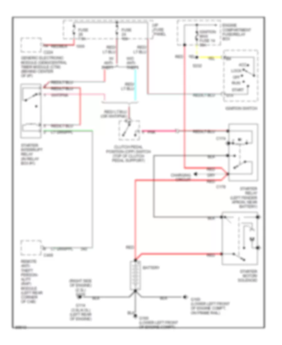 https://portal-diagnostov.com/license.html
Automotive Electricians Portal FZCO
Automotive Electricians Portal FZCO
https://portal-diagnostov.com/license.html
https://portal-diagnostov.com/license.html
Automotive Electricians Portal FZCO
Automotive Electricians Portal FZCOList of elements for Starting Wiring Diagram, M/T for Ford Ranger Splash 1997:
- (right side of engine) (2.3l) g120
- Acc
- Battery
- C174
- C178
- C224
- C409
- Charging circuit
- Clutch pedal position (cpp) switch (top of clutch pedal support)
- Engine compartment fuse/relay box
- Fuse 10a
- Fuse 7.5a
- G100 (lower left front of engine compt)
- G100 (lower left front of engine compt, on frame rail)
- G114 (3.0l/4.ol) (left rear of engine)
- Generic electronic module (gem)/central timer module (ctm) (behind center of i/p)
- I/p fuse panel
- Ignition maxi fuse 14 50a
- Ignition switch
- Lock
- Off
- Pnk
- Red
- Remote anti- theft person- ality (rap) module (left rear corner of cab)
- Run
- S232
- Sta
- Start
- Starter interrupt relay (in relay box #1)
- Starter motor/ solenoid
- Starter relay (left fender apron, near battery)
- W/ anti- theft
- W/o anti- theft
SUPPLEMENTAL RESTRAINTS
Supplemental Restraint Wiring Diagram, with Passenger Deactivation for Ford Ranger Splash 1997
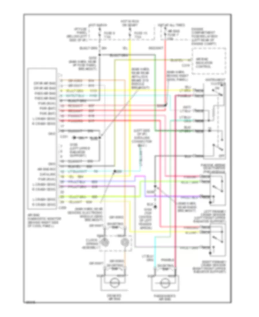 https://portal-diagnostov.com/license.html
Automotive Electricians Portal FZCO
Automotive Electricians Portal FZCO
https://portal-diagnostov.com/license.html
https://portal-diagnostov.com/license.html
Automotive Electricians Portal FZCO
Automotive Electricians Portal FZCOList of elements for Supplemental Restraint Wiring Diagram, with Passenger Deactivation for Ford Ranger Splash 1997:
- (left side of i/p) data link connector (dlc)
- (main harn, behind right cowl panel)
- (main harn, near generic electronic module (gem) breakout)
- (main harn, near radio breakout)
- (main harn, near rear anti-lock brake sys module breakout)
- Air bag diagnostic monitor (behind right side of cowl panel)
- Air bag fuse 7 10a
- Air bag ind
- Air bag indicator control
- C216
- C250
- C251
- Clock- spring assembly
- Data link
- Driver's air bag
- Drvr air bag
- Engine compartment fuse/relay box (left rear of engine compt)
- Fuse 15 7.5a
- Fuse 6 7.5a
- G104 (top center of left fender apron)
- G108 (left upper radiator support)
- Gnd
- Hot at all times
- Hot in run
- Hot in run or start
- I/p fuse panel (below left side of i/p)
- Instrument cluster
- L crash sens
- Left primary crash sensor (left front upper radiator support)
- Nca
- Off
- Pass air bag
- Passenger's air bag
- Passive airbag deactivation (pad) module
- Pwr (bat)
- Pwr (run)
- R crash sens
- Right primary crash sensor (right front upper radiator support)
- S200
- S205
- S209
- S225
- S250 (main harn, near i/p fuse panel breakout)
- Shorting bar
Supplemental Restraint Wiring Diagram, without Passenger Deactivation for Ford Ranger Splash 1997
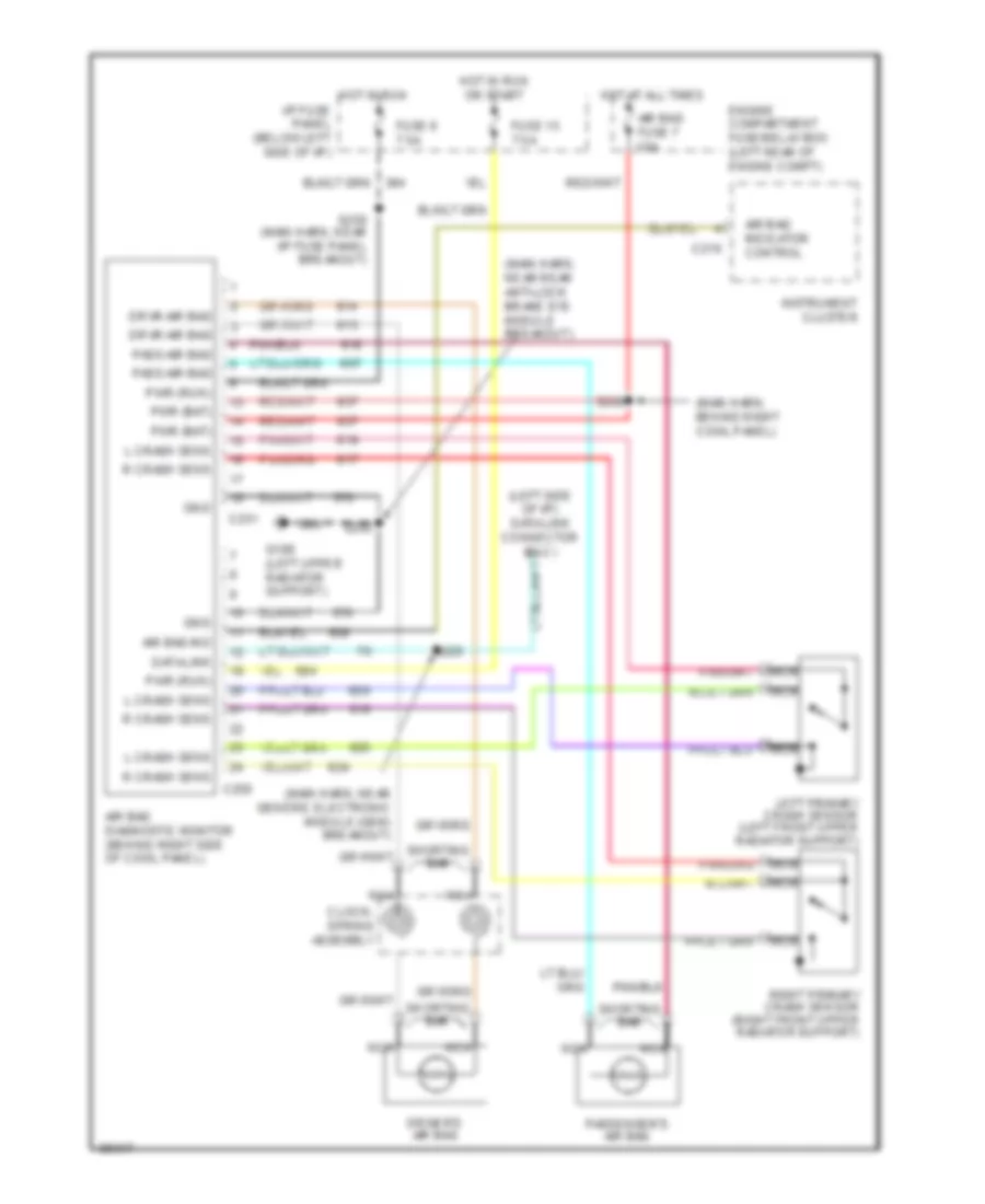 https://portal-diagnostov.com/license.html
Automotive Electricians Portal FZCO
Automotive Electricians Portal FZCO
https://portal-diagnostov.com/license.html
https://portal-diagnostov.com/license.html
Automotive Electricians Portal FZCO
Automotive Electricians Portal FZCOList of elements for Supplemental Restraint Wiring Diagram, without Passenger Deactivation for Ford Ranger Splash 1997:
- (left side of i/p) data link connector (dlc)
- (main harn, behind right cowl panel)
- (main harn, near generic electronic module (gem) breakout)
- (main harn, near rear anti-lock brake sys module breakout)
- Air bag diagnostic monitor (behind right side of cowl panel)
- Air bag fuse 7 10a
- Air bag ind
- Air bag indicator control
- C216
- C250
- C251
- Clock- spring assembly
- Data link
- Driver's air bag
- Drvr air bag
- Engine compartment fuse/relay box (left rear of engine compt)
- Fuse 15 7.5a
- Fuse 6 7.5a
- G108 (left upper radiator support)
- Gnd
- Hot at all times
- Hot in run
- Hot in run or start
- I/p fuse panel (below left side of i/p)
- Instrument cluster
- L crash sens
- Left primary crash sensor (left front upper radiator support)
- Nca
- Pass air bag
- Passenger's air bag
- Pwr (bat)
- Pwr (run)
- R crash sens
- Right primary crash sensor (right front upper radiator support)
- S200
- S205
- S225
- S250 (main harn, near i/p fuse panel breakout)
- Shorting bar
TRANSMISSION
2.3L
2.3L, Transmission Wiring Diagram, 4R44E for Ford Ranger Splash 1997
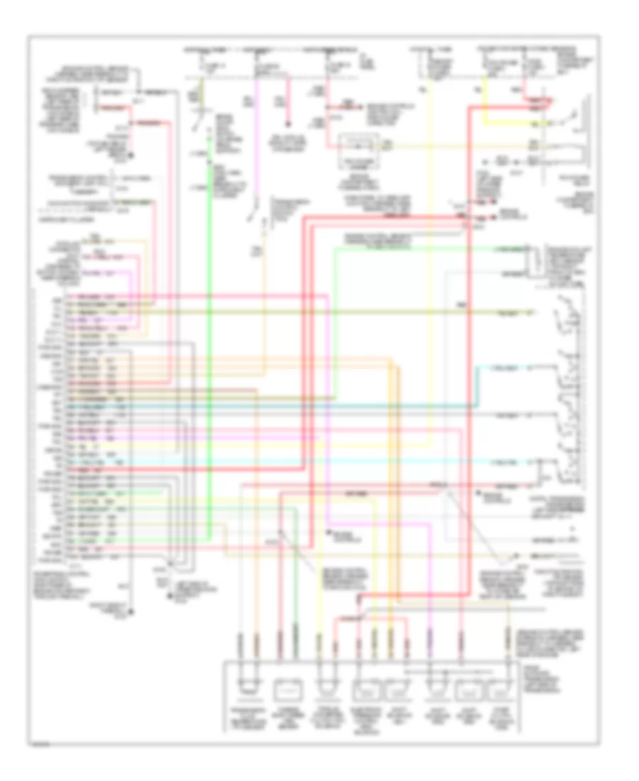 https://portal-diagnostov.com/license.html
Automotive Electricians Portal FZCO
Automotive Electricians Portal FZCO
https://portal-diagnostov.com/license.html
https://portal-diagnostov.com/license.html
Automotive Electricians Portal FZCO
Automotive Electricians Portal FZCOList of elements for 2.3L, Transmission Wiring Diagram, 4R44E for Ford Ranger Splash 1997:
- (dash panel to headlamp junction harness, near breakout to left headlamp)
- (engine control sensor extension harness, near breakout to harness in-line connector, left rear of engine)
- (engine control sensor harness, near breakout to ground g123)
- (engine control sensor harness, near breakout to intake air temp (iat) sensor)
- (engine control sensor harness, near breakout to throttle position (tp) sensor)
- (left side of upper radiator support) g108
- (power for heated oxygen sensors)
- (right side of firewall) g123
- (top center of left fender apron) g104
- 4r44e automatic transmission (left side of transmission)
- Boo
- Brake on/off (boo) switch (on brake pedal support)
- C111
- C214
- C216
- Case gnd
- Ccs
- Coast clutch solenoid (css)
- Cse gnd
- Digital transmission range sensor (left side of trans)
- Dlc
- Dlc (+)
- Dlc (-)
- Drl module, backup lamps, dtr sensor
- Ect
- Electronic pressure control (epc) solenoid
- Engine compartment fuse/relay box
- Engine controls
- Engine controls (ignition coil, radio noise capacitor)
- Engine coolant temperature (ect) sensor (top right front of eng, in water outlet tube)
- Epc
- Fuse 13 15a
- Fuse 19 25a
- Fuse 26 10a
- G108 (left side of upper radiator support)
- Ho2s fuse 3 15a
- Hot at all times
- Hot in run
- Hot in start or run
- I/p fuse panel
- Instrument cluster
- Kapwr
- Malfunction indicator lamp (mil)
- Memory power fuse 5 15a
- Mil
- O/d off
- Pcm power diode
- Pcm power fuse 2 30a
- Pcm power relay
- Power
- Powertrain control module (pcm) (right rear of engine compartment, through firewall)
- Pwr gnd
- R p
- Red
- S100
- S1002
- S102
- S103
- S104
- S106
- S110
- S111
- S121
- S147
- S228 (main harn, near breakout to instrument cluster)
- Shift solenoid (ss1)
- Shift solenoid (ss2)
- Shift solenoid (ss3)
- Sig rtn
- Ss1
- Ss2
- Ss3
- Tcc
- Tcil
- Tcs
- Tft
- Throttle position (tp) sensor (top right side of engine, on throttle body)
- Torque converter clutch (tcc) solenoid
- Tr1
- Tr2
- Tr4
- Transmission control indicator lamp (tcil)
- Transmission control switch (tcs)
- Transmission fluid temperature (tft) sensor
- Tss
- Turbine shaft speed (tss) sensor
- Vehicle speed sensor (vss) (left rear of transmission) (4x2 models) (left rear of transfer case) (4x4 models)
- Vref
- Vss
Transfer Case Wiring Diagram for Ford Ranger Splash 1997
 https://portal-diagnostov.com/license.html
Automotive Electricians Portal FZCO
Automotive Electricians Portal FZCO
https://portal-diagnostov.com/license.html
https://portal-diagnostov.com/license.html
Automotive Electricians Portal FZCO
Automotive Electricians Portal FZCOList of elements for Transfer Case Wiring Diagram for Ford Ranger Splash 1997:
- (behind dash, right side of steering column) relay box 1
- (main harness, in breakout to generic electronic module (gem) connectors)
- (main harness, near breakout to dash fuse panel)
- (top center of left fender apron) g104
- 1.1k ohms
- 3.9k ohms
- 4 wheel drive fuse 4 20a
- 4wd hi ind
- 4wd ind ctrl
- 4wd lo ind
- 4wd mode sw
- 4wd mode switch
- 4wd motor
- 4wd output
- Battery saver relay
- Boo sw input
- Brake on/off (boo) switch (on brake pedal support)
- C214
- C221
- C223
- C224
- Ccw relay
- Ccw rly ctrl
- Clutch
- Cw relay
- Cw rly ctrl
- Digital transmission range (dtr) sensor (left side of transmission)
- Elc rly ctrl
- Electric clutch relay
- Electric shift control module (behind center of dash)
- Engine compartment fuse/relay box
- Fuse 13 15a
- Fuse 27 15a
- Fuse 3 in i/p fuse panel (feed to park lamps relay)
- G104 (top center of left fender apron)
- Generic electronic module (gem) (behind center of dash)
- Hot at all times
- I/p fuse panel
- Illumination
- Instrument cluster
- Interior lights
- Interior lights system (instrument illum- ination circuit)
- Nca
- Neutral sw in
- Of firewall) g123
- Ohms
- Park lamps fuse 8 20a
- Pnk
- Relay box 1 (behind dash, right side of steering column)
- Rly ctrl
- S107
- S111 (engine control sensor harness, near breakout to fuel injector 6)
- S209
- S215
- S216
- S218
- S221
- S224
- S228 (main harness, near breakout to instrument cluster connectors)
- S237
- Sig return
- Sw a input
- Sw b input
- Sw c input
- Sw d input
- Touch drive
- Transfer case assembly (below vehicle, behind transmission)
- Vehicle speed sensor (vss) (4x4 models - left rear of transfer case) (4x2 models - left rear of trans)
- Vss
- Wiper/washer (multi-function switch)
3.0L
3.0L, Transmission Wiring Diagram, 4R44E for Ford Ranger Splash 1997
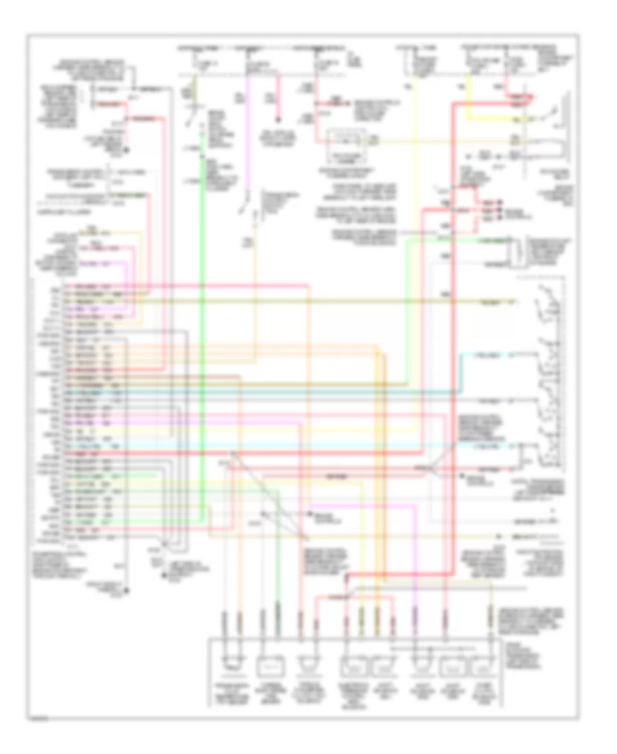 https://portal-diagnostov.com/license.html
Automotive Electricians Portal FZCO
Automotive Electricians Portal FZCO
https://portal-diagnostov.com/license.html
https://portal-diagnostov.com/license.html
Automotive Electricians Portal FZCO
Automotive Electricians Portal FZCOList of elements for 3.0L, Transmission Wiring Diagram, 4R44E for Ford Ranger Splash 1997:
- (dash panel to headlamp junction harness, near breakout to left headlamp)
- (engine control sensor extension harness, near breakout to harness in-line connector, left rear of engine)
- (engine control sensor harn, near breakout to in-line conn, at left rear of engine)
- (engine control sensor harness, near breakout to diff press feedback sensor)
- (engine control sensor harness, near breakout to evr solenoid)
- (engine control sensor harness, near breakout to in-line connector, at left rear of engine)
- (engine control sensor harness, near breakout to octane adjust shorting bar)
- (left side of upper radiator support) g108
- (power for heated oxygen sensors)
- (right side of firewall) g123
- (top center of left fender apron) g104
- 4r44e automatic transmission (left side of transmission)
- Boo
- Brake on/off (boo) switch (on brake pedal support)
- C111
- C214
- C216
- Case gnd
- Ccs
- Coast clutch solenoid (css)
- Cse gnd
- Digital transmission range sensor (left side of trans)
- Dlc
- Dlc (+)
- Dlc (-)
- Drl module, backup lamps, dtr sensor
- Ect
- Electronic pressure control (epc) solenoid
- Engine compartment fuse/relay box
- Engine controls
- Engine controls (ignition coil, radio noise capacitor)
- Engine coolant temperature (ect) sensor (top front of engine)
- Epc
- Fuse 13 15a
- Fuse 19 25a
- Fuse 26 10a
- G108 (left side of radiator support)
- Ho2s fuse 3 15a
- Hot at all times
- Hot in run
- Hot in start or run
- I/p fuse panel
- Instrument cluster
- Kapwr
- Malfunction indicator lamp (mil)
- Memory power fuse 5 15a
- Mil
- O/d off
- Pcm power diode
- Pcm power fuse 2 30a
- Pcm power relay
- Power
- Powertrain control module (pcm) (right rear of engine compartment, through firewall)
- Pwr gnd
- R p
- Red
- S100 (engine control sensor harness, near breakout to intake air temp sensor)
- S1002
- S102
- S103
- S104
- S106
- S110
- S111
- S112
- S113
- S121
- S147
- S228 (main harn, near breakout to instrument cluster)
- Shift solenoid (ss1)
- Shift solenoid (ss2)
- Shift solenoid (ss3)
- Sig rtn
- Ss1
- Ss2
- Ss3
- Tcc
- Tcil
- Tcs
- Tft
- Throttle position (tp) sensor (top right side of engine, on throttle body)
- Torque converter clutch (tcc) solenoid
- Tr1
- Tr2
- Tr4
- Transmission control indicator lamp (tcil)
- Transmission control switch (tcs)
- Transmission fluid temperature (tft) sensor
- Tss
- Turbine shaft speed (tss) sensor
- Vehicle speed sensor (vss) (left rear of transmission) (4x2 models) (left rear of transfer case) (4x4 models)
- Vref
- Vss
Transfer Case Wiring Diagram for Ford Ranger Splash 1997
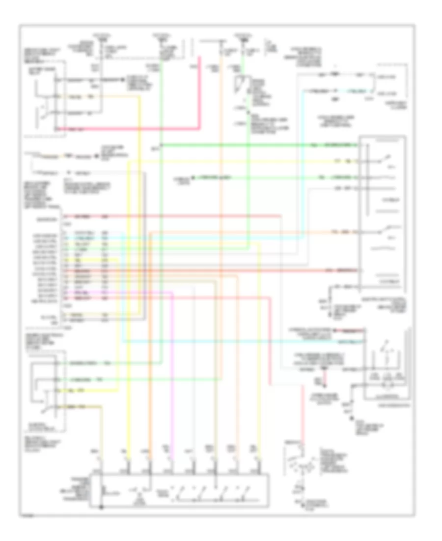 https://portal-diagnostov.com/license.html
Automotive Electricians Portal FZCO
Automotive Electricians Portal FZCO
https://portal-diagnostov.com/license.html
https://portal-diagnostov.com/license.html
Automotive Electricians Portal FZCO
Automotive Electricians Portal FZCOList of elements for Transfer Case Wiring Diagram for Ford Ranger Splash 1997:
- (behind dash, right side of steering column) relay box 1
- (main harness, in breakout to generic electronic module (gem) connectors)
- (main harness, near breakout to dash fuse panel)
- (top center of left fender apron) g104
- 1.1k ohms
- 3.9k ohms
- 4 wheel drive fuse 4 20a
- 4wd hi ind
- 4wd ind ctrl
- 4wd lo ind
- 4wd mode sw
- 4wd mode switch
- 4wd motor
- 4wd output
- Battery saver relay
- Boo sw input
- Brake on/off (boo) switch (on brake pedal support)
- C214
- C221
- C223
- C224
- Ccw relay
- Ccw rly ctrl
- Clutch
- Cw relay
- Cw rly ctrl
- Digital transmission range (dtr) sensor (left side of transmission)
- Elc rly ctrl
- Electric clutch relay
- Electric shift control module (behind center of dash)
- Engine compartment fuse/relay box
- Fuse 13 15a
- Fuse 27 15a
- Fuse 3 in i/p fuse panel (feed to park lamps relay)
- G104 (top center of left fender apron)
- Generic electronic module (gem) (behind center of dash)
- Hot at all times
- I/p fuse panel
- Illumination
- Instrument cluster
- Interior lights
- Interior lights system (instrument illum- ination circuit)
- Nca
- Neutral sw in
- Of firewall) g123
- Ohms
- Park lamps fuse 8 20a
- Pnk
- Relay box 1 (behind dash, right side of steering column)
- Rly ctrl
- S107
- S111 (engine control sensor harness, near breakout to fuel injector 6)
- S209
- S215
- S216
- S218
- S221
- S224
- S228 (main harness, near breakout to instrument cluster connectors)
- S237
- Sig return
- Sw a input
- Sw b input
- Sw c input
- Sw d input
- Touch drive
- Transfer case assembly (below vehicle, behind transmission)
- Vehicle speed sensor (vss) (4x4 models - left rear of transfer case) (4x2 models - left rear of trans)
- Vss
- Wiper/washer (multi-function switch)
4.0L
4.0L, Transmission Wiring Diagram, 5R55E for Ford Ranger Splash 1997
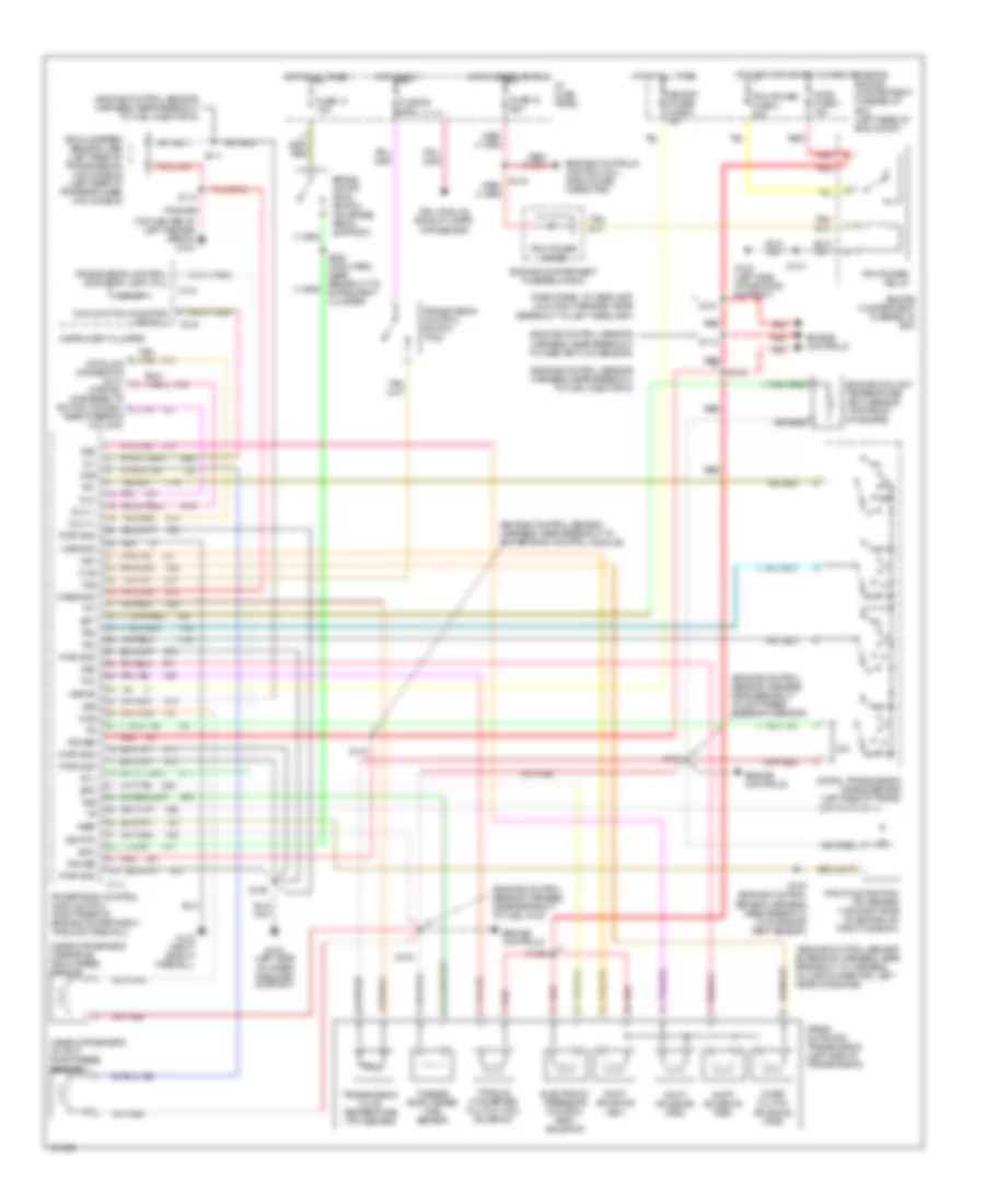 https://portal-diagnostov.com/license.html
Automotive Electricians Portal FZCO
Automotive Electricians Portal FZCO
https://portal-diagnostov.com/license.html
https://portal-diagnostov.com/license.html
Automotive Electricians Portal FZCO
Automotive Electricians Portal FZCOList of elements for 4.0L, Transmission Wiring Diagram, 5R55E for Ford Ranger Splash 1997:
- (dash panel to headlamp junction harness, near breakout to left headlamp)
- (engine control sensor extension harness, near breakout to harness in-line connector, left rear of engine)
- (engine control sensor harness, near breakout to diff press feedback sensor)
- (engine control sensor harness, near breakout to fuel inj 6)
- (engine control sensor harness, near breakout to fuel injector 5)
- (engine control sensor harness, near breakout to fuel injector 6)
- (engine control sensor harness, near breakout to mass air flow sensor)
- (engine control sensor harness, near breakout to powertrain control module)
- (near dtr sensor) output shaft speed sensor
- (near dtr sensor) overdrive drum speed sensor
- (power for heated oxygen sensors)
- (top center of left fender apron) g104
- 5r55e automatic transmission (left side of transmission)
- Boo
- Brake on/off (boo) switch (on brake pedal support)
- C111
- C214
- C216
- Case gnd
- Ccs
- Coast clutch solenoid (css)
- Cse gnd
- Digital transmission range sensor (left side of trans)
- Dlc
- Dlc (+)
- Dlc (-)
- Drl module, backup lamps, dtr sensor
- Ect
- Electronic pressure control (epc) solenoid
- Engine compartment fuse/relay box
- Engine compartment fuse/relay box (left rear of eng compt)
- Engine controls
- Engine controls (ignition coil, radio noise capacitor)
- Engine coolant temperature (ect) sensor (top front of engine)
- Epc
- Fuse 13 15a
- Fuse 19 25a
- Fuse 26 10a
- G108 (left side of radiator support)
- G108 (left side of upper radiator support)
- G123 (right side of firewall)
- Ho2s fuse 3 15a
- Hot at all times
- Hot in run
- Hot in start or run
- I/p fuse panel
- Instrument cluster
- Kapwr
- Malfunction indicator lamp (mil)
- Memory power fuse 5 15a
- Mil
- O/d off
- Ods
- Oss
- Pcm power diode
- Pcm power fuse 2 30a
- Pcm power relay
- Power
- Powertrain control module (pcm) (right rear of engine compartment, through firewall)
- Pwr gnd
- R p
- Red
- S100 (engine control sensor harness, near breakout to intake air temp sensor)
- S1002
- S102
- S103
- S104
- S106
- S110
- S111
- S112
- S113
- S121
- S147
- S228 (main harn, near breakout to instrument cluster)
- Shift solenoid (ss1)
- Shift solenoid (ss2)
- Shift solenoid (ss3)
- Sig rtn
- Ss1
- Ss2
- Ss3
- Tcc
- Tcil
- Tcs
- Tft
- Throttle position (tp) sensor (top right side of engine, on throttle body)
- Torque converter clutch (tcc) solenoid
- Tr1
- Tr2
- Tr4
- Transmission control indicator lamp (tcil)
- Transmission control switch (tcs)
- Transmission fluid temperature (tft) sensor
- Tss
- Turbine shaft speed (tss) sensor
- Vehicle speed sensor (vss) (left rear of transmission) (4x2 models) (left rear of transfer case) (4x4 models)
- Vref
- Vss
Transfer Case Wiring Diagram for Ford Ranger Splash 1997
 https://portal-diagnostov.com/license.html
Automotive Electricians Portal FZCO
Automotive Electricians Portal FZCO
https://portal-diagnostov.com/license.html
https://portal-diagnostov.com/license.html
Automotive Electricians Portal FZCO
Automotive Electricians Portal FZCOList of elements for Transfer Case Wiring Diagram for Ford Ranger Splash 1997:
- (behind dash, right side of steering column) relay box 1
- (main harness, in breakout to generic electronic module (gem) connectors)
- (main harness, near breakout to dash fuse panel)
- (top center of left fender apron) g104
- 1.1k ohms
- 3.9k ohms
- 4 wheel drive fuse 4 20a
- 4wd hi ind
- 4wd ind ctrl
- 4wd lo ind
- 4wd mode sw
- 4wd mode switch
- 4wd motor
- 4wd output
- Battery saver relay
- Boo sw input
- Brake on/off (boo) switch (on brake pedal support)
- C214
- C221
- C223
- C224
- Ccw relay
- Ccw rly ctrl
- Clutch
- Cw relay
- Cw rly ctrl
- Digital transmission range (dtr) sensor (left side of transmission)
- Elc rly ctrl
- Electric clutch relay
- Electric shift control module (behind center of dash)
- Engine compartment fuse/relay box
- Fuse 13 15a
- Fuse 27 15a
- Fuse 3 in i/p fuse panel (feed to park lamps relay)
- G104 (top center of left fender apron)
- Generic electronic module (gem) (behind center of dash)
- Hot at all times
- I/p fuse panel
- Illumination
- Instrument cluster
- Interior lights
- Interior lights system (instrument illum- ination circuit)
- Nca
- Neutral sw in
- Of firewall) g123
- Ohms
- Park lamps fuse 8 20a
- Pnk
- Relay box 1 (behind dash, right side of steering column)
- Rly ctrl
- S107
- S111 (engine control sensor harness, near breakout to fuel injector 6)
- S209
- S215
- S216
- S218
- S221
- S224
- S228 (main harness, near breakout to instrument cluster connectors)
- S237
- Sig return
- Sw a input
- Sw b input
- Sw c input
- Sw d input
- Touch drive
- Transfer case assembly (below vehicle, behind transmission)
- Vehicle speed sensor (vss) (4x4 models - left rear of transfer case) (4x2 models - left rear of trans)
- Vss
- Wiper/washer (multi-function switch)
WARNING SYSTEMS
Warning System Wiring Diagrams for Ford Ranger Splash 1997
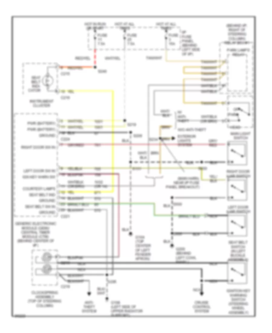 https://portal-diagnostov.com/license.html
Automotive Electricians Portal FZCO
Automotive Electricians Portal FZCO
https://portal-diagnostov.com/license.html
https://portal-diagnostov.com/license.html
Automotive Electricians Portal FZCO
Automotive Electricians Portal FZCOList of elements for Warning System Wiring Diagrams for Ford Ranger Splash 1997:
- (behind i/p, right of steering column) relay box #1
- (main harn, near i/p fuse panel breakout)
- (or 14)
- Anti- theft system
- C215
- C216
- C219
- C221
- C224
- Clockspring assembly (top of steering column)
- Courtesy lamps
- Cruise control system
- Exterior lights system
- Fuse 15a
- Fuse 7.5a
- G104 (top center of left fender apron)
- G108 (left side of upper radiator support)
- G200 (behind left cowl panel)
- Generic electronic module (gem)/ central timer module (ctm) (behind center of i/p)
- Ground
- Head
- Hot at all times
- Hot in run or start
- I/p fuse panel (behind left side of i/p)
- Ign key warn sw
- Ignition key warning switch (steering wheel assembly)
- Instrument cluster
- Left door ajar switch
- Left door sw in
- Main light switch
- Nca
- Off
- Park
- Park lamps relay
- Pwr (battery)
- Right door ajar switch
- Right door sw in
- S131
- S205
- S209
- S219
- S234
- S240
- S300
- S600
- Seat belt ind
- Seat belt indi- cator
- Seat belt sw in
- Seat belt switch (in left buckle assembly)
- W/ anti- theft
- W/o anti-theft
WIPER/WASHER
Wiper/Washer Wiring Diagram for Ford Ranger Splash 1997
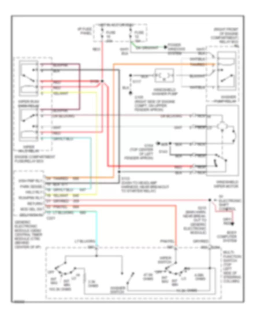 https://portal-diagnostov.com/license.html
Automotive Electricians Portal FZCO
Automotive Electricians Portal FZCO
https://portal-diagnostov.com/license.html
https://portal-diagnostov.com/license.html
Automotive Electricians Portal FZCO
Automotive Electricians Portal FZCOList of elements for Wiper/Washer Wiring Diagram for Ford Ranger Splash 1997:
- (right fromt of engine compartment) relay box #2
- 103.3k ohms
- 11.3k
- 3.3k ohms
- 4.08k
- Body computer system
- C221
- C254
- Dely/wsh in
- Engine compartment fuse/relay box
- Fuse 10a
- Fuse 30a
- G104 (top center of left fender apron)
- G105 (right side of engine compt, on upper fender apron)
- Generic electronic module (gem)/ central timer module (ctm) (behind center of i/p)
- Hi/lo rly
- Hot in acc or run
- I/p fuse panel
- Int max
- Int min
- Mod sel sw
- Multi- function switch (top left side of steering column)
- Nca
- Nca hi
- Nca lo
- Off
- Off 47.6k ohms
- Ohms
- Park sense
- Power windows system
- Red
- Return
- Run/prk rly
- S117
- S133 (dash to headlamp harness, near breakout to starter relay)
- S138
- S143
- S215 (main harn, near break- out to generic electronic module)
- Tan/red
- W/ electronic shift control
- Washer pump relay
- Washer switch
- Windshield washer pump
- Windshield wiper motor
- Wiper hi-lo relay
- Wiper run/ park relay
- Wiper switch
- Wsh pmp rly

 Čeština
 Dansk
Dansk Deutsch
 Ελληνικά
 English
 English
 Español
 Suomi
Suomi Français
 Français
 עברית
עברית Hrvatski
 Magyar
 Italiano
 日本語
日本語 한국어
한국어 Nederlands
 Polski
 Português
 Português
 Română
 Русский
 Slovenčina
 Slovenščina
 Svenska
 中文 (中国)
