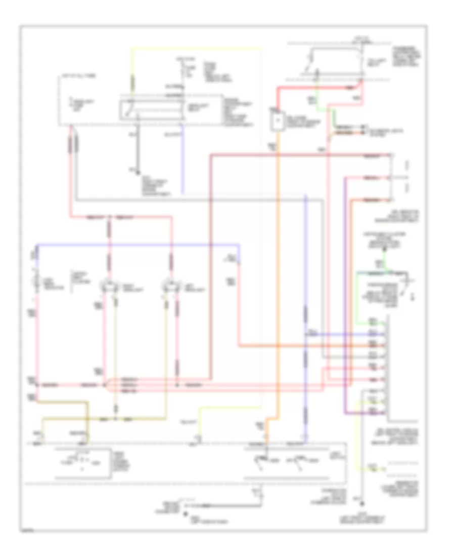
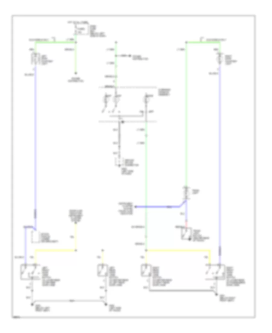
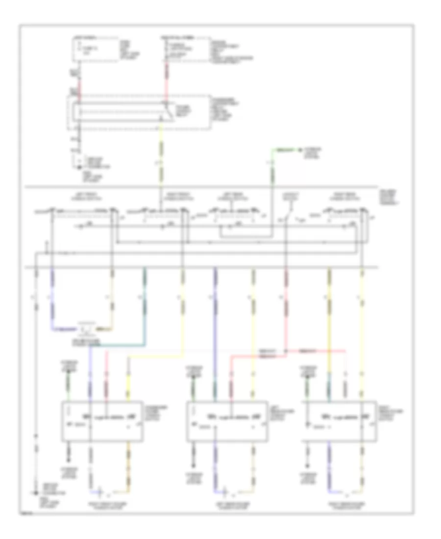
AIR CONDITIONING
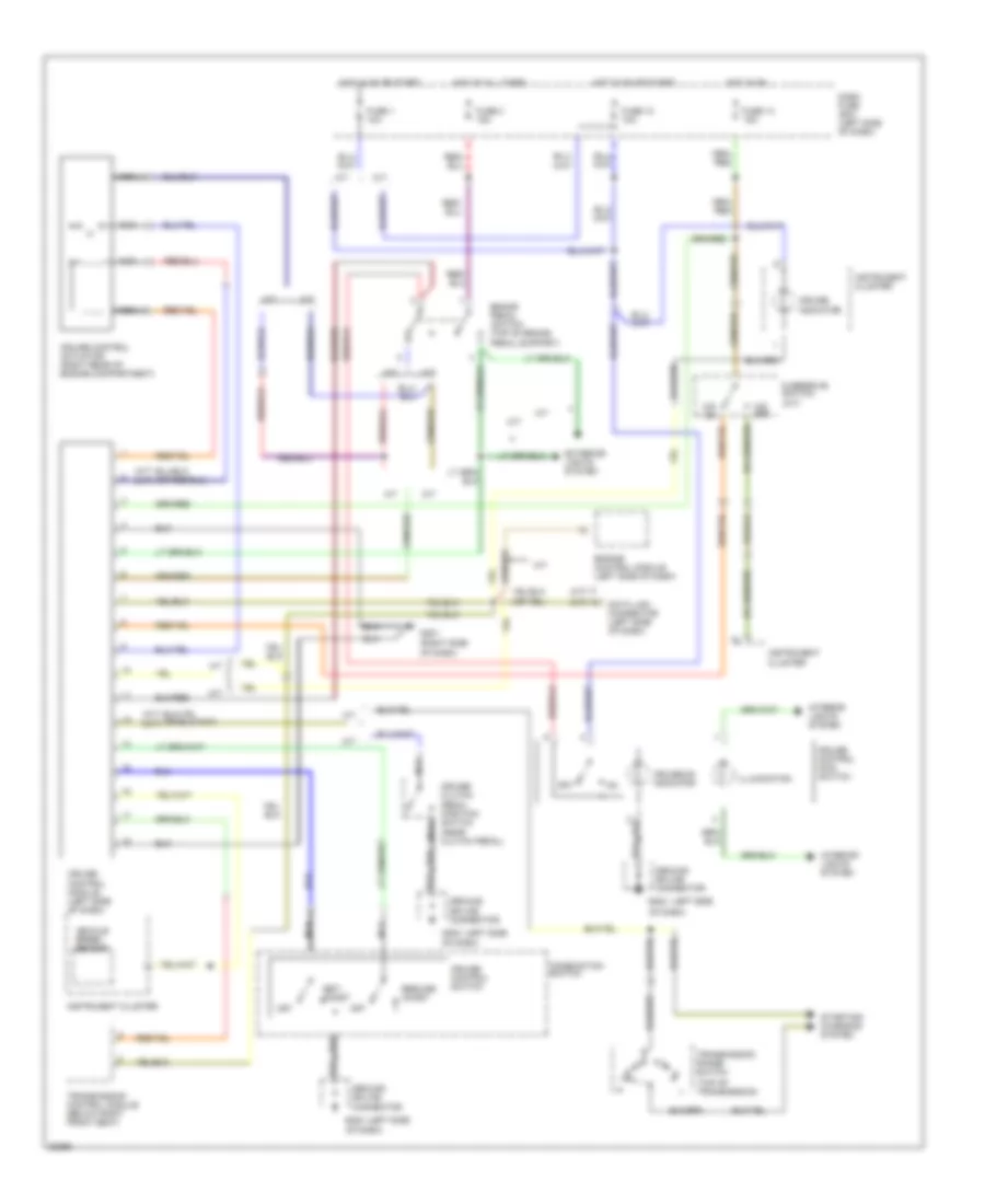
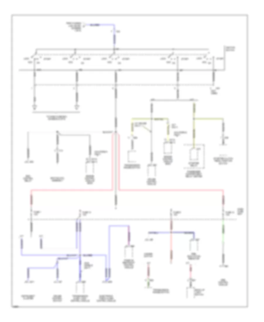
A/C Wiring Diagram for Hyundai Elantra 1995
 https://portal-diagnostov.com/license.html
Automotive Electricians Portal FZCO
Automotive Electricians Portal FZCO
https://portal-diagnostov.com/license.html
https://portal-diagnostov.com/license.html
Automotive Electricians Portal FZCO
Automotive Electricians Portal FZCO
List of elements for A/C Wiring Diagram for Hyundai Elantra 1995:
- (right front
- A/c compressor
- A/c control relay (right front corner of engine compartment)
- A/c diode (behind center of i/p, taped to harness)
- A/c dual pressure switch (left rear corner of engine compartment)
- A/c switch
- A/con #2 fuse 10a
- A/con#1 fuse 10a
- Blower fuse 30a
- Blower motor
- Blower relay (in passenger compartment relay center)
- Blower resistors (behind right side of i/p)
- Blower switch
- C 1995 vftc
- C01-4
- C01-6
- Closed
- Condenser fan motor
- Condenser fan motor relay (in engine compartment relay box)
- Corner of
- Dash fuse box
- E26
- Em-03
- Engine compartment relay box
- Engine compartment)
- Engine control module (behind left side of i/p)
- Engine coolant fan a/c on relay (in engine compartment relay box)
- Engine coolant fan motor
- Engine coolant fan motor relay (in engine compartment relay box)
- Engine coolant temperature switch a (lower right front of engine compartment, rear of radiator)
- Engine coolant temperature switch b (top side of engine on coolant outlet)
- Engine coolant temperature switch c (lower right front of engine compartment, rear of radiator)
- Evaporator temperature switch (above glove box)
- Fresh
- Fuse 10a
- Fuse 12 10a
- Fuse 15a
- Fusible link (c/fan) 10a
- Fusible link (rad) 20a (pnk)
- G100 (left front corner of engine compartment)
- G101
- G200 (behind left kick panel)
- Headlights
- Heater- a/c control panel
- Hot at all times
- Hot in on
- Illumi- nation
- Indi- cator
- Interior lights system
- Off
- On indicator
- Open
- Recirc
- Red
- Transmission control module
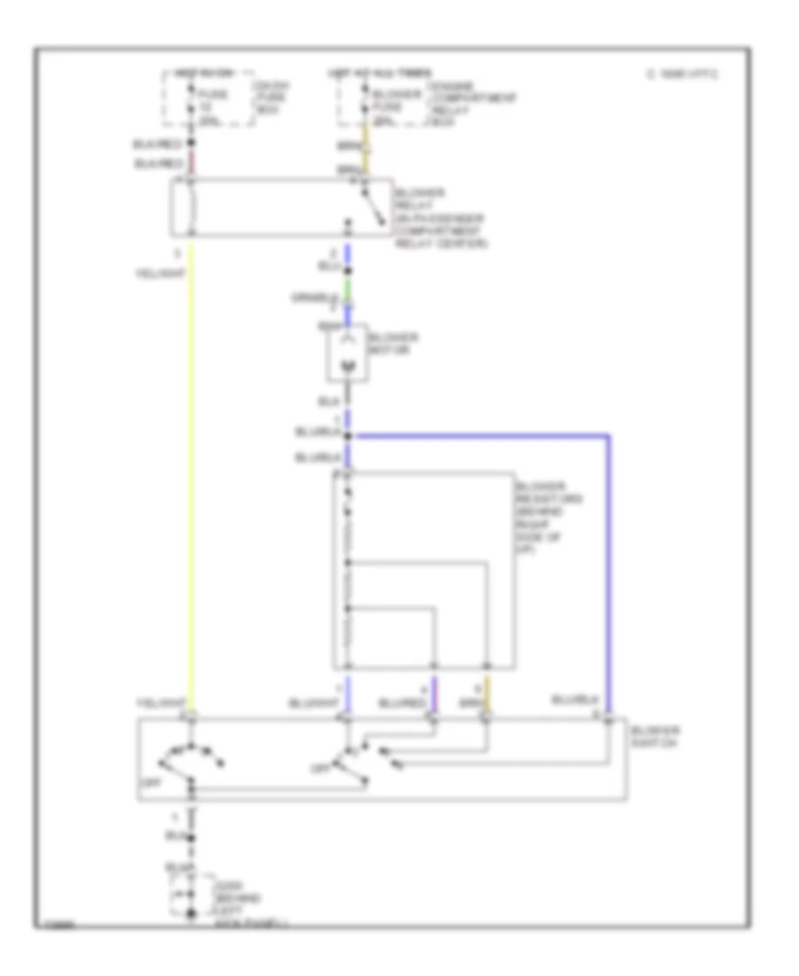
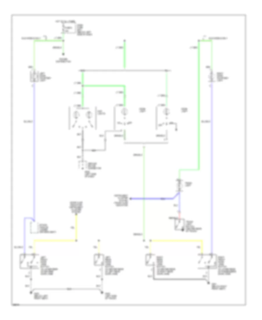
Heater Wiring Diagram for Hyundai Elantra 1995
 https://portal-diagnostov.com/license.html
Automotive Electricians Portal FZCO
Automotive Electricians Portal FZCO
https://portal-diagnostov.com/license.html
https://portal-diagnostov.com/license.html
Automotive Electricians Portal FZCO
Automotive Electricians Portal FZCOList of elements for Heater Wiring Diagram for Hyundai Elantra 1995:
- Blower fuse 30a
- Blower motor
- Blower relay (in passenger compartment relay center)
- Blower resistors (behind right side of i/p)
- Blower switch
- C 1995 vftc
- Dash fuse box
- Engine compartment relay box
- Fuse 10a
- G200 (behind left kick panel)
- Hot at all times
- Hot in on
- Off
ANTI-LOCK BRAKES
Anti-lock Brake Wiring Diagrams for Hyundai Elantra 1995
 https://portal-diagnostov.com/license.html
Automotive Electricians Portal FZCO
Automotive Electricians Portal FZCO
https://portal-diagnostov.com/license.html
https://portal-diagnostov.com/license.html
Automotive Electricians Portal FZCO
Automotive Electricians Portal FZCOList of elements for Anti-lock Brake Wiring Diagrams for Hyundai Elantra 1995:
- Abs ind
- Abs modulator (right rear of engine compartment)
- Abs pump motor (right rear of engine compartment)
- Abs pump motor relay
- Abs relay box (rear of engine compartment)
- Antilock brake control module (trunk compartment, inside right rear fender)
- Brake pedal switch (brake pedal support)
- Dash fuse box
- Dash fuse box (left side of i/p)
- Data link connector
- E72
- E73
- Engine compartment relay box (right front of engine compt)
- Fail safe relay
- Fuse 1 10a
- Fuse 10 10a
- Fuse 13 10a
- Fuse 3 15a
- Fusible link (abs#2) pnk 30a
- G101 (right front of engine compartment)
- G301 (below right front seat)
- Hot at all times
- Hot in on
- Hot in on or start
- Inline diode
- Instrument cluster
- Left front sol
- Left front wheel sensor
- Left rear sol
- Left rear wheel sensor
- Passenger compartment relay center (behind left side of i/p)
- Pnk
- Red
- Right front sol
- Right front wheel sensor
- Right rear sol
- Right rear wheel sensor
COMPUTER DATA LINES
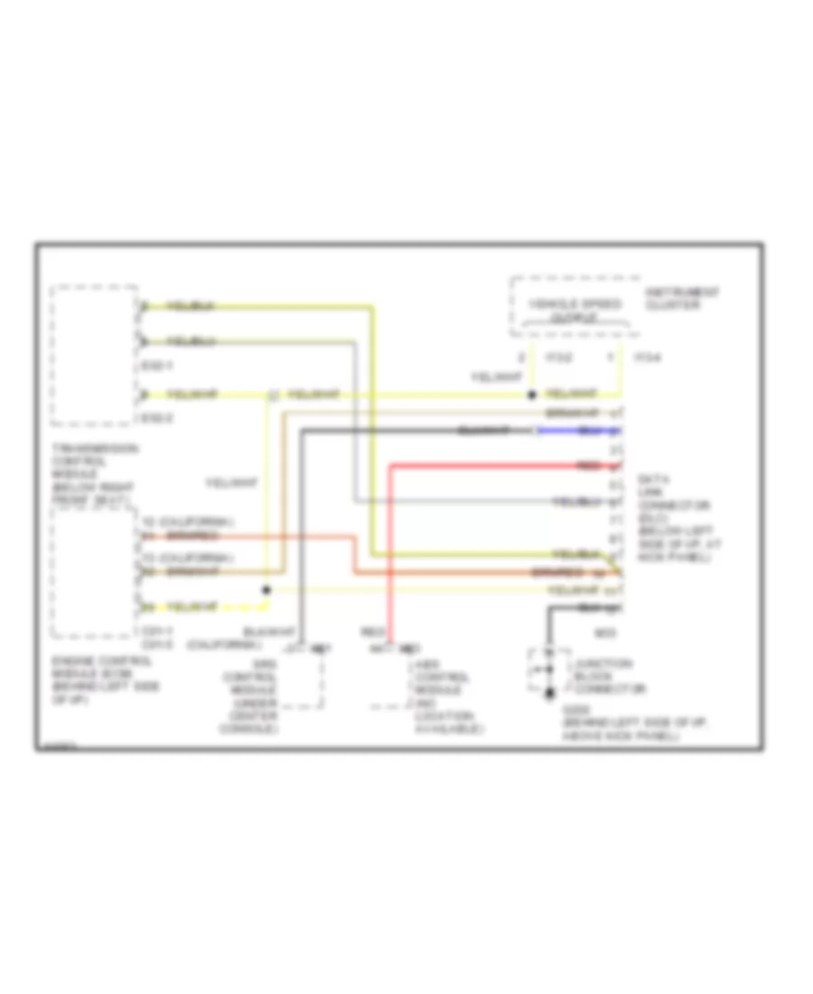
Computer Data Lines for Hyundai Elantra 1995
 https://portal-diagnostov.com/license.html
Automotive Electricians Portal FZCO
Automotive Electricians Portal FZCO
https://portal-diagnostov.com/license.html
https://portal-diagnostov.com/license.html
Automotive Electricians Portal FZCO
Automotive Electricians Portal FZCOList of elements for Computer Data Lines for Hyundai Elantra 1995:
- (california)
- Abs control module (no location available)
- C01-1 c01-5
- Data link connector (dlc) (below left side of i/p, at kick panel)
- E02-1
- E02-2
- Engine control module (ecm) (behind left side of i/p)
- G202 (behind left side of i/p, above kick panel)
- I13-2
- I13-4
- Instrument cluster
- Junction block connector
- M33
- M81
- M93
- Red
- Srs control module (under center console)
- Transmission control module (below right front seat)
- Vehicle speed output
COOLING FAN
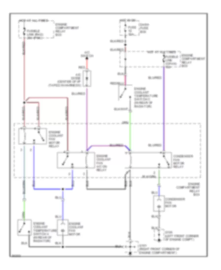
Cooling Fan Wiring Diagram for Hyundai Elantra 1995
 https://portal-diagnostov.com/license.html
Automotive Electricians Portal FZCO
Automotive Electricians Portal FZCO
https://portal-diagnostov.com/license.html
https://portal-diagnostov.com/license.html
Automotive Electricians Portal FZCO
Automotive Electricians Portal FZCOList of elements for Cooling Fan Wiring Diagram for Hyundai Elantra 1995:
- A/c diode (center of i/p (taped in harness)
- A/c switch
- Condenser fan motor
- Condenser fan motor relay
- Dash fuse box
- Engine compartment relay box
- Engine coolant fan a/c on relay
- Engine coolant fan motor
- Engine coolant fan motor relay
- Engine coolant temperature switch a (in rear of radiator)
- Engine coolant temperature switch c (in rear of radiator)
- Fuse 10a
- Fusible link (c/fan) 10a
- Fusible link (rad) 20a (pnk)
- G100 (left front corner of engine compt)
- G101 (right front corner of engine compartment)
- Hot at all times
- Hot in on
- Red
CRUISE CONTROL
Cruise Control Wiring Diagram for Hyundai Elantra 1995
 https://portal-diagnostov.com/license.html
Automotive Electricians Portal FZCO
Automotive Electricians Portal FZCO
https://portal-diagnostov.com/license.html
https://portal-diagnostov.com/license.html
Automotive Electricians Portal FZCO
Automotive Electricians Portal FZCOList of elements for Cruise Control Wiring Diagram for Hyundai Elantra 1995:
- (a/t)
- (m/t)
- (near clutch pedal)
- (right side of dash)
- (top of transmission)
- A/t
- Brake pedal switch (top of brake pedal support)
- Combination switch
- Cruise indicator
- Cruise clutch pedal position switch
- Cruise control actuator (right rear of engine compartment)
- Cruise control main switch
- Cruise control module (left side of dash)
- Cruise control switch
- Cruise on indicator
- Dash fuse box (left side of dash)
- Data link connector (left side of dash)
- Engine control module (left side of dash)
- Exterior lights system
- Fuse 1 10a
- Fuse 10 10a
- Fuse 13 15a
- Fuse 3 15a
- G201
- G202 (left side
- Ground splice connector
- Hot at all times
- Hot in on
- Hot in on or start
- Illumination
- Instrument cluster
- Interior lights system
- M/t
- Nca
- O/d off
- O/d on
- Of dash)
- Off
- Overdrive switch (a/t)
- Resume/ coast
- Set/ coast
- Starting/ charging system
- Transmission control module (below right front seat)
- Transmission range switch
- Vehicle speed sensor
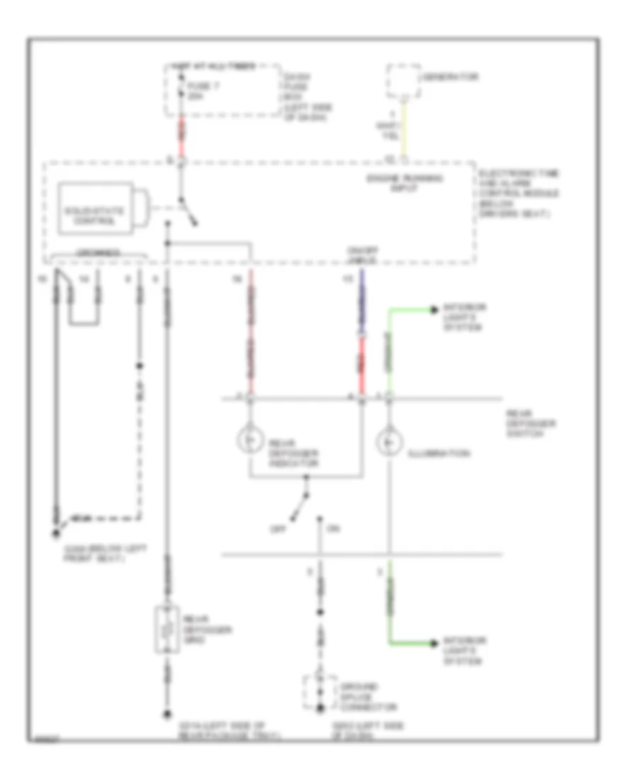
DEFOGGERS
Defogger Wiring Diagram for Hyundai Elantra 1995
 https://portal-diagnostov.com/license.html
Automotive Electricians Portal FZCO
Automotive Electricians Portal FZCO
https://portal-diagnostov.com/license.html
https://portal-diagnostov.com/license.html
Automotive Electricians Portal FZCO
Automotive Electricians Portal FZCOList of elements for Defogger Wiring Diagram for Hyundai Elantra 1995:
- (below left g300
- (left side g202
- (left side of g314
- Dash fuse box (left side of dash)
- Electronic time and alarm control module (below drivers seat)
- Engine running input
- Front seat)
- Fuse 7 20a
- Generator
- Ground splice connector
- Grounds
- Hot at all times
- Illumination
- Interior lights system
- Of dash)
- Off
- On/off input
- Rear defogger grid
- Rear defogger indicator
- Rear defogger switch
- Rear package tray)
- Red
- Solid-state control
ENGINE PERFORMANCE
1.6L
1.6L, Engine Performance Wiring Diagrams (1 of 2) for Hyundai Elantra 1995
 https://portal-diagnostov.com/license.html
Automotive Electricians Portal FZCO
Automotive Electricians Portal FZCO
https://portal-diagnostov.com/license.html
https://portal-diagnostov.com/license.html
Automotive Electricians Portal FZCO
Automotive Electricians Portal FZCOList of elements for 1.6L, Engine Performance Wiring Diagrams (1 of 2) for Hyundai Elantra 1995:
- (behind left side of
- (behind left side of i/p, above kick panel)
- (behind left side of i/p, on ecm bracket)
- (center rear of
- (dash fuse box)
- (left side of engine compt,
- A/c relay ctrl
- A/c request in
- A/t
- A/t only
- Acc
- Air conditioning
- Air conditioning system
- Air flow sensor in
- Baro press sensor in
- Battery
- Battery back-up
- C 1995 vftc
- C01-4
- C01-5
- C01-6
- Coil control
- Cp sensor in
- Cruise control system
- Dash fuse box (below left side of i/p)
- Data link connector
- Diagnosis
- Diagnosis ctrl signal
- Early prod.
- Ecm control relay
- Ecm relay ctrl
- Ect sensor in
- Egr control solenoid
- Egr solenoid ctrl
- Egr temp sensor in
- Elect spark timing
- Electronic spark timing adjust connector (left side of engine compt, taped to harness)
- Engine compartment relay box (right side of engine compt)
- Engine compt)
- Engine control module (behind left side of i/p)
- Frt htd oxy sensor in
- Fuel inj #1 ctrl
- Fuel inj #2 ctrl
- Fuel inj #3 ctrl
- Fuel inj #4 ctrl
- Fuel injectors
- Fuel pump (inside top left corner of fuel tank,
- Fuel pump ctrl
- Fuel pump inspection connector
- Fuse 10a
- G200
- G202
- G300 (under driver's seat)
- Ground
- Hot at all times
- Hot in on or start
- I/p, above kick panel)
- Iat sensor in
- Idle position sw in
- Idle speed mtr ctrl
- Ig1
- Ignition
- Ignition switch
- Instrument cluster
- Late prod.
- Lock
- M/t
- Malfunction ind ctrl
- Malfunction indicator
- Near filler hose)
- No.1
- No.2
- No.3
- No.4
- P/n (a/t),ground (m/t)
- Power steering pressure switch (left front corner of engine, in power steering oil pump)
- Purge control solenoid
- Purge ctrl solenoid
- Pwr steering press in
- Red
- Rpm signal in
- Rr htd oxy sensor in
- Sensor ground
- Sensor pwr-5v
- Start
- Starting signal in
- System
- Taped to harness)
- Tdc sensor in
- Tps in
- Transmission system
- Vehicle speed in
1.6L, Engine Performance Wiring Diagrams (2 of 2) for Hyundai Elantra 1995
 https://portal-diagnostov.com/license.html
Automotive Electricians Portal FZCO
Automotive Electricians Portal FZCO
https://portal-diagnostov.com/license.html
https://portal-diagnostov.com/license.html
Automotive Electricians Portal FZCO
Automotive Electricians Portal FZCOList of elements for 1.6L, Engine Performance Wiring Diagrams (2 of 2) for Hyundai Elantra 1995:
- (behind left side of i/p, above kick panel)
- (behind left side of i/p, on ecm bracket)
- (closed w/ clutch pedal depressed) (on clutch pedal bracket)
- (left rear corner of engine,
- (right side of i/p, behind kick panel)
- (right side of intake manifold, near coolant outlet)
- A/t
- A/t only
- Barometric pressure sensor
- C 1995 vftc
- Condenser
- Crankshaft position sensor (right side of engine, near coolant outlet)
- Egr temperature sensor (right rear of engine, in egr valve)
- Engine coolant temperature sensor
- Front heated oxygen sensor (on exhaust pipe, in front of catalytic converter)
- G116
- G200
- G202
- G203
- Idle position switch (top right rear corner of engine, on throttle body)
- Idle speed control motor (right rear of engine, below intake manifold)
- Ignition coil assembly
- Ignition coils
- Instrument cluster
- Instrument cluster system (tachometer)
- Intake air temperature sensor
- M/t
- M/t only
- Nca
- Noise filter (top left rear of engine, on air inlet surge tank assembly)
- On front of cowl top panel)
- Position sensor (top right side of engine, on throttle body)
- Power transistor (lower left rear corner of engine)
- Rear heated oxygen sensor (on exhaust pipe, behind catalytic converter)
- Red
- Red pwr
- Solid state
- Spark plugs
- Starter clutch pedal position switch
- Starter relay (in passenger compt relay center)
- Starting system
- Tach interface
- Throttle
- Transmission range switch (closed in park & neutral) (lower right front of engine, (in top of transmission)
- Transmission system
- Under intake manifold)
- Vehicle speed output
- Vehicle speed sensor
- Volume air flow sensor
- Volume air flow sensor assembly (right side of engine compt, in air cleaner assembly)
1.8L
1.8L, Engine Performance Wiring Diagrams (1 of 2) for Hyundai Elantra 1995
 https://portal-diagnostov.com/license.html
Automotive Electricians Portal FZCO
Automotive Electricians Portal FZCO
https://portal-diagnostov.com/license.html
https://portal-diagnostov.com/license.html
Automotive Electricians Portal FZCO
Automotive Electricians Portal FZCOList of elements for 1.8L, Engine Performance Wiring Diagrams (1 of 2) for Hyundai Elantra 1995:
- (behind left side of
- (behind left side of i/p, above kick panel)
- (behind left side of i/p, on ecm bracket)
- (center rear of
- (dash fuse box)
- (left side of engine compt,
- A/c relay ctrl
- A/c request in
- A/t
- A/t only
- Acc
- Air conditioning
- Air conditioning system
- Air flow sensor in
- Baro press sensor in
- Battery
- Battery back-up
- C 1995 vftc
- C01-4
- C01-5
- C01-6
- Coil control
- Cp sensor in
- Cruise control system
- Dash fuse box (below left side of i/p)
- Data link connector
- Diagnosis
- Diagnosis ctrl signal
- Early prod.
- Ecm control relay
- Ecm relay ctrl
- Ect sensor in
- Egr control solenoid
- Egr solenoid ctrl
- Egr temp sensor in
- Elect spark timing
- Electronic spark timing adjust connector (left side of engine compt, taped to harness)
- Engine compartment relay box (right side of engine compt)
- Engine compt)
- Engine control module (behind left side of i/p)
- Frt htd oxy sensor in
- Fuel inj #1 ctrl
- Fuel inj #2 ctrl
- Fuel inj #3 ctrl
- Fuel inj #4 ctrl
- Fuel injectors
- Fuel pump (inside top left corner of fuel tank,
- Fuel pump ctrl
- Fuel pump inspection connector
- Fuse 10a
- G200
- G202
- G300 (under driver's seat)
- Ground
- Hot at all times
- Hot in on or start
- I/p, above kick panel)
- Iat sensor in
- Idle position sw in
- Idle speed mtr ctrl
- Ig1
- Ignition
- Ignition switch
- Instrument cluster
- Late prod.
- Lock
- M/t
- Malfunction ind ctrl
- Malfunction indicator
- Near filler hose)
- No.1
- No.2
- No.3
- No.4
- P/n (a/t),ground (m/t)
- Power steering pressure switch (left front corner of engine, in power steering oil pump)
- Purge control solenoid
- Purge ctrl solenoid
- Pwr steering press in
- Red
- Rpm signal in
- Rr htd oxy sensor in
- Sensor ground
- Sensor pwr-5v
- Start
- Starting signal in
- System
- Taped to harness)
- Tdc sensor in
- Tps in
- Transmission system
- Vehicle speed in
1.8L, Engine Performance Wiring Diagrams (2 of 2) for Hyundai Elantra 1995
 https://portal-diagnostov.com/license.html
Automotive Electricians Portal FZCO
Automotive Electricians Portal FZCO
https://portal-diagnostov.com/license.html
https://portal-diagnostov.com/license.html
Automotive Electricians Portal FZCO
Automotive Electricians Portal FZCOList of elements for 1.8L, Engine Performance Wiring Diagrams (2 of 2) for Hyundai Elantra 1995:
- (behind left side of i/p, above kick panel)
- (behind left side of i/p, on ecm bracket)
- (closed w/ clutch pedal depressed) (on clutch pedal bracket)
- (left rear corner of engine,
- (right side of i/p, behind kick panel)
- (right side of intake manifold, near coolant outlet)
- A/t
- A/t only
- Barometric pressure sensor
- C 1995 vftc
- Condenser
- Crankshaft position sensor (right side of engine, near coolant outlet)
- Egr temperature sensor (right rear of engine, in egr valve)
- Engine coolant temperature sensor
- Front heated oxygen sensor (on exhaust pipe, in front of catalytic converter)
- G116
- G200
- G202
- G203
- Idle position switch (top right rear corner of engine, on throttle body)
- Idle speed control motor (right rear of engine, below intake manifold)
- Ignition coil assembly
- Ignition coils
- Instrument cluster
- Instrument cluster system (tachometer)
- Intake air temperature sensor
- M/t
- M/t only
- Nca
- Noise filter (top left rear of engine, on air inlet surge tank assembly)
- On front of cowl top panel)
- Position sensor (top right side of engine, on throttle body)
- Power transistor (lower left rear corner of engine)
- Rear heated oxygen sensor (on exhaust pipe, behind catalytic converter)
- Red
- Red pwr
- Solid state
- Spark plugs
- Starter clutch pedal position switch
- Starter relay (in passenger compt relay center)
- Starting system
- Tach interface
- Throttle
- Transmission range switch (closed in park & neutral) (lower right front of engine, (in top of transmission)
- Transmission system
- Under intake manifold)
- Vehicle speed output
- Vehicle speed sensor
- Volume air flow sensor
- Volume air flow sensor assembly (right side of engine compt, in air cleaner assembly)
EXTERIOR LIGHTS
Back-up Lamps Wiring Diagram for Hyundai Elantra 1995
 https://portal-diagnostov.com/license.html
Automotive Electricians Portal FZCO
Automotive Electricians Portal FZCO
https://portal-diagnostov.com/license.html
https://portal-diagnostov.com/license.html
Automotive Electricians Portal FZCO
Automotive Electricians Portal FZCOList of elements for Back-up Lamps Wiring Diagram for Hyundai Elantra 1995:
- A/t
- Back up light
- Back up lights switch (in front of transmission)
- Dash fuse box (below left side of dash, at kick panel)
- Fuse 9 10a
- G405 (right rear of trunk)
- Hot in on and start
- M/t
- Nca
- Red
- Transaxle range switch (in top of transmission)
Exterior Lamps Wiring Diagram (1 of 3) for Hyundai Elantra 1995
 https://portal-diagnostov.com/license.html
Automotive Electricians Portal FZCO
Automotive Electricians Portal FZCO
https://portal-diagnostov.com/license.html
https://portal-diagnostov.com/license.html
Automotive Electricians Portal FZCO
Automotive Electricians Portal FZCOList of elements for Exterior Lamps Wiring Diagram (1 of 3) for Hyundai Elantra 1995:
- 10a
- Combination switch
- Dash fuse box (below left side of dash, at kick panel)
- Digital clock
- Drl control module (behind left headlight)
- Drl diode
- Engine compartment relay box (right side of engine compartment, in front of shock tower)
- Fender)
- From brake pedal switch (diagram 3 of 3)
- From combination switch (diagram 2 of 3)
- Fuse 16
- Fuse 17
- G100 (left front
- G101 (right front
- G202 (left side
- G400 (left side
- G405 (right rear
- Ground splice connector
- Head
- Hot at all times
- Interior lights system
- Left tail/stop light
- Left front park/turn light
- Left license light
- Light switch
- Of dash)
- Of trunk)
- Off
- Park
- Passenger compartment relay center (behind left side of dash, left of steering column)
- Power distribution
- Red
- Right front park/turn light
- Right license light
- Right tail/stop light
- Taillight relay
- W/ drl
- W/o drl
Exterior Lamps Wiring Diagram (2 of 3) for Hyundai Elantra 1995
 https://portal-diagnostov.com/license.html
Automotive Electricians Portal FZCO
Automotive Electricians Portal FZCO
https://portal-diagnostov.com/license.html
https://portal-diagnostov.com/license.html
Automotive Electricians Portal FZCO
Automotive Electricians Portal FZCOList of elements for Exterior Lamps Wiring Diagram (2 of 3) for Hyundai Elantra 1995:
- Coil control
- Combination meter
- Combination switch
- Dash fuse box (below left side of dash, at kick panel)
- Fuse 2 10a
- Fuse 9 10a
- G202 (left side
- G405 (right rear
- Ground
- Ground splice connector
- Haz
- Hazard switch
- Hot at all times
- Hot in on and start
- I13-1
- I13-3
- Illumination
- Interior lights system
- Left
- Left rear turn light
- Left turn indicator
- Norm
- Not used
- Of dash)
- Of trunk)
- Passenger compartment relay center (behind left side of dash, left of steering column)
- Power
- Right
- Right rear turn light
- Right turn indicator
- To left front park/turn light (diagram 1 of 3)
- To right front park/turn light (diagram 1 of 3)
- Turn signal switch
- Turn/ hazard flasher
Exterior Lamps Wiring Diagram (3 of 3) for Hyundai Elantra 1995
 https://portal-diagnostov.com/license.html
Automotive Electricians Portal FZCO
Automotive Electricians Portal FZCO
https://portal-diagnostov.com/license.html
https://portal-diagnostov.com/license.html
Automotive Electricians Portal FZCO
Automotive Electricians Portal FZCOList of elements for Exterior Lamps Wiring Diagram (3 of 3) for Hyundai Elantra 1995:
- (under center of dash)
- A/t
- Abs control module (in trunk compartment)
- Brake pedal switch (top of brake pedal support bracket)
- Cruise control actuator (right rear corner 0f engine compartment)
- Cruise control main switch
- Cruise control module (behind right side of dash, at kick panel)
- Dash fuse box (below left side of dash, at kick panel)
- Fuse 3 15a
- G400 (left side of trunk)
- High mount stop light
- Hot at all times
- M/t
- Nca
- Passenger compartment relay center (behind left side of dash, left of steering column)
- To tail/stop lights (diagram 1 of 3)
- Transmission and key lock control module
- With cruise control
- With abs
- Without cruise control
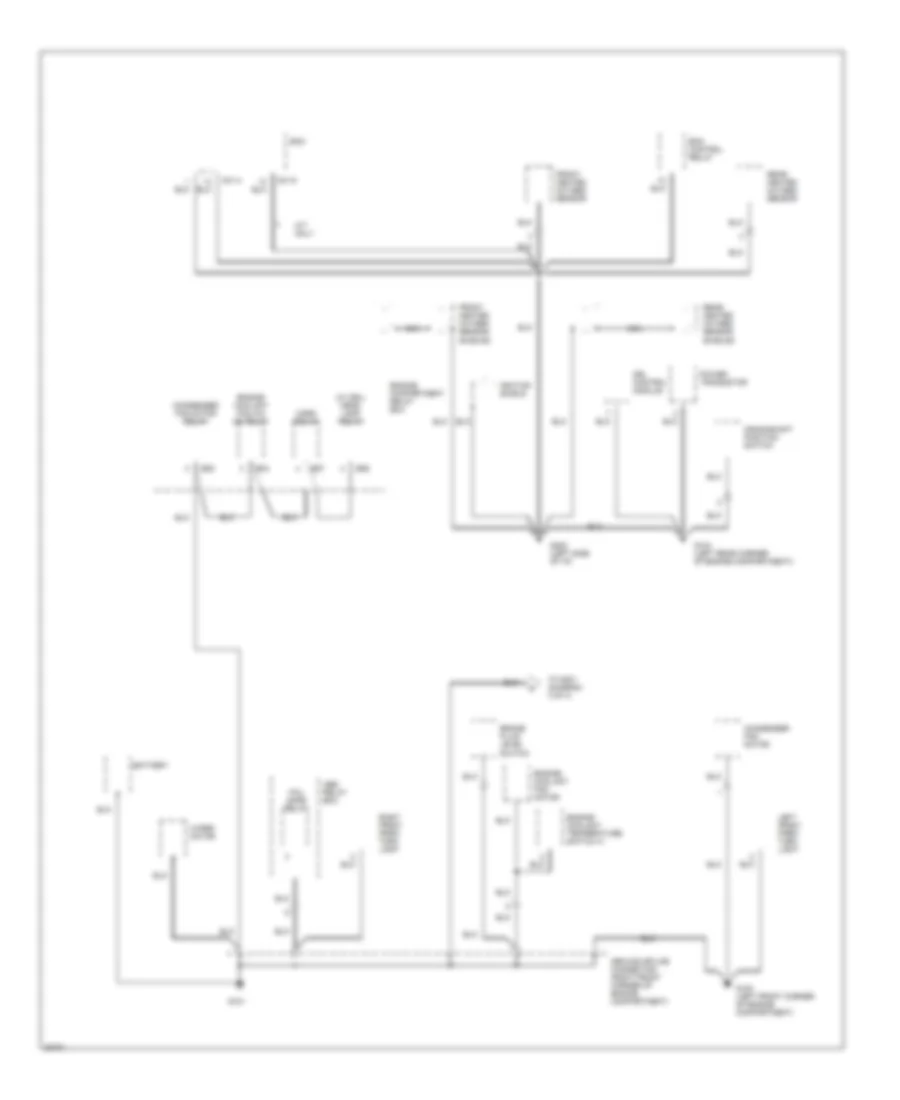
GROUND DISTRIBUTION
Ground Distribution Wiring Diagram (1 of 4) for Hyundai Elantra 1995
 https://portal-diagnostov.com/license.html
Automotive Electricians Portal FZCO
Automotive Electricians Portal FZCO
https://portal-diagnostov.com/license.html
https://portal-diagnostov.com/license.html
Automotive Electricians Portal FZCO
Automotive Electricians Portal FZCOList of elements for Ground Distribution Wiring Diagram (1 of 4) for Hyundai Elantra 1995:
- (w/ drl) head- lamp relay
- Abs relay box
- Battery
- Brake fluid level switch
- C01-4
- C01-5
- Condenser fan motor
- Condenser fan motor relay
- Crankshaft position switch
- Drl control module
- E04
- E05
- E06
- E57
- Ecm
- Ecm control relay
- Engine compartment relay box
- Engine coolant fan a/c on relay
- Engine coolant fan motor
- Engine coolant temperature switch a
- Fail safe relay
- Front heated oxygen sensor
- Front heated oxygen sensor shields
- G100 (left front corner of engine compartment)
- G101
- G104 (left rear corner of engine compartment))
- G202 (left side of i/p)
- Ground splice connector (right front corner of engine compartment)
- Horn relay
- Ignition shield
- Left front park/ turn light
- M/t only
- Nca
- Power transistor
- Rear heated oxygen sensor
- Rear heated oxygen sensor shields
- Right front park/ turn light
- To g301 (diagram 3 of 4)
- Wiper motor
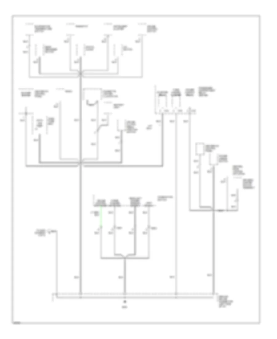
Ground Distribution Wiring Diagram (2 of 4) for Hyundai Elantra 1995
 https://portal-diagnostov.com/license.html
Automotive Electricians Portal FZCO
Automotive Electricians Portal FZCO
https://portal-diagnostov.com/license.html
https://portal-diagnostov.com/license.html
Automotive Electricians Portal FZCO
Automotive Electricians Portal FZCOList of elements for Ground Distribution Wiring Diagram (2 of 4) for Hyundai Elantra 1995:
- A/c switch
- Ashtray light
- Blower switch
- Central door locking actuator
- Cigarette lighter illumination
- Combination switch
- Cruise clutch pedal position switch
- Cruise control switch
- Cruise control switches
- Dash fuse box
- Data link conn.
- Digital clock
- Driver's master switch assembly
- Evaporator temperature switch
- G202
- Ground splice connector (left side of i/p)
- Headlight dimmer/ passing switch
- Heater-a/c control panel
- Instrument cluster
- Light switch
- M/t only
- M15
- M16
- M19
- M26-1
- M26-2
- Nca
- Passenger compartment relay center
- Power mirror switch
- Power window relay
- Radio
- Rear defogger switch
- Rheostat
- Starter relay
- To g400 (diagram 4 of 4)
- Turn/ hazard flasher
- Wiper/ washer switches
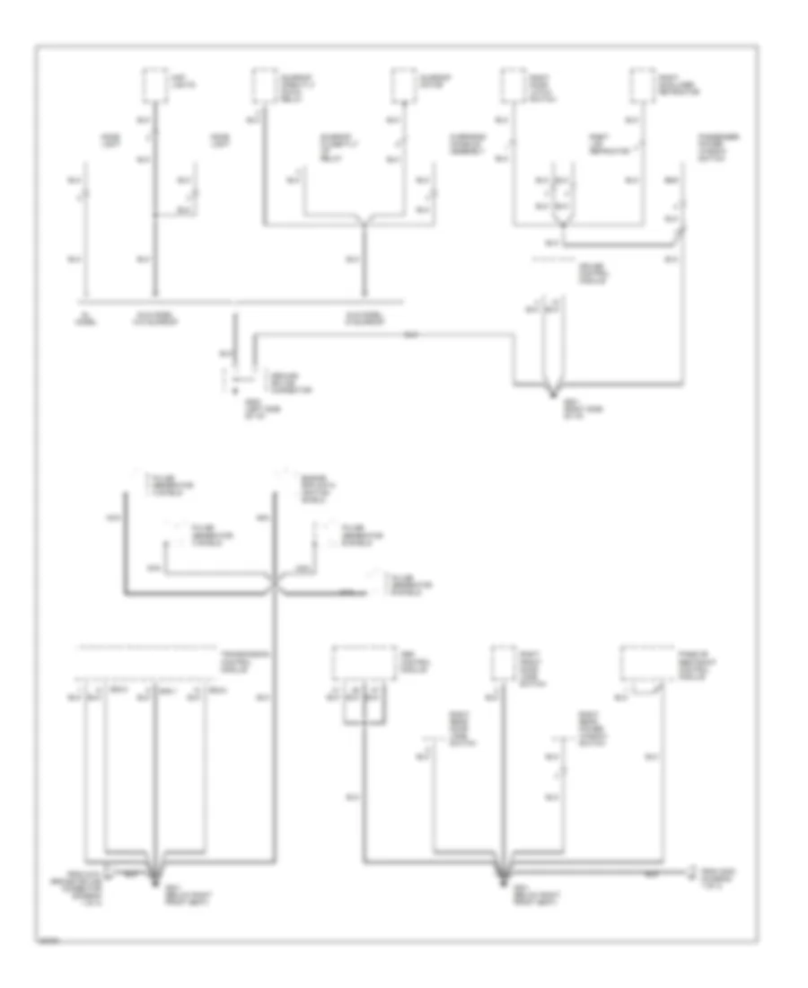
Ground Distribution Wiring Diagram (3 of 4) for Hyundai Elantra 1995
 https://portal-diagnostov.com/license.html
Automotive Electricians Portal FZCO
Automotive Electricians Portal FZCO
https://portal-diagnostov.com/license.html
https://portal-diagnostov.com/license.html
Automotive Electricians Portal FZCO
Automotive Electricians Portal FZCOList of elements for Ground Distribution Wiring Diagram (3 of 4) for Hyundai Elantra 1995:
- Abs control module
- Cruise control module
- Dome light
- E02-1
- E02-2
- E02-3
- Engine rpm data ignition shield
- From g101 a ground splice connector (diagram 1 of 4)
- From g300 (diagram 1 of 4)
- G201 (right side of i/p)
- G202 (left side of i/p)
- G301 (below right front seat)
- Gl model
- Gls model w/ sunroof
- Gls model w/o sunroof
- Ground splice connector
- Map lights
- Nca
- Overhead console assembly
- Passenger power window switch
- Passive restraint control module
- Pulse generator a shield
- Pulse generator b shield
- Right door latch switch
- Right front door jamb switch
- Right lap retractor
- Right rear door jamb switch
- Right rear power window switch
- Right shoulder retractor
- Sunroof close/tilt up relay
- Sunroof motor
- Sunroof open/tilt down relay
- Transmission control module
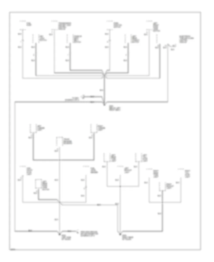
Ground Distribution Wiring Diagram (4 of 4) for Hyundai Elantra 1995
 https://portal-diagnostov.com/license.html
Automotive Electricians Portal FZCO
Automotive Electricians Portal FZCO
https://portal-diagnostov.com/license.html
https://portal-diagnostov.com/license.html
Automotive Electricians Portal FZCO
Automotive Electricians Portal FZCOList of elements for Ground Distribution Wiring Diagram (4 of 4) for Hyundai Elantra 1995:
- Electronic time and alarm control module
- From g202 ground splice connector (diagram 2 of 4)
- Fuel level sender
- Fuel pump
- G300 (below left front seat)
- G400 (left side of trunk)
- G405 (right rear of trunk)
- High mount stop light
- Key lock switch
- Left backup light
- Left front door jamb switch
- Left license light
- Left rear door jamb switch
- Left rear turn light
- Left rear window switch
- Left tail/ stop light
- Park position switch
- Passive seat belt switch
- Right backup light
- Right license light
- Right rear turn light
- Right tail/ stop light
- To g301 (diagram 3 of 4)
- Transmission and key lock control module
- Trunk release solenoid
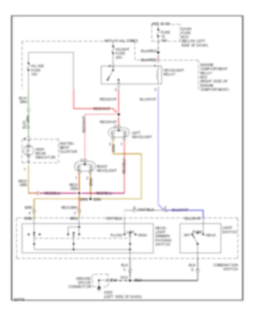
HEADLIGHTS
Headlight Wiring Diagram, with DRL for Hyundai Elantra 1995
 https://portal-diagnostov.com/license.html
Automotive Electricians Portal FZCO
Automotive Electricians Portal FZCO
https://portal-diagnostov.com/license.html
https://portal-diagnostov.com/license.html
Automotive Electricians Portal FZCO
Automotive Electricians Portal FZCOList of elements for Headlight Wiring Diagram, with DRL for Hyundai Elantra 1995:
- (left front of engine compartment, behind left headlight)
- Combination switch (left side of steering column)
- Dash fuse box (below left side of dash)
- Drl control module
- Drl diode (front of engine compartment)
- Drl resistor (right front of engine compartment)
- Engine compartment relay box (right side of engine compartment)
- Exterior lights system
- Flash
- Fuse 10a
- G100 (left front corner of engine compartment)
- G101 (right front corner of engine compartment)
- G202 (left side of dash)
- Generator (lower left front corner of engine compartment)
- Ground splice connector
- Head
- Head- light dimmer/ passing switch
- Headlight fuse 20a
- Headlight relay
- High
- High beam indicator
- Hot at all times
- Hot in on
- Instru- ment cluster
- Instrument cluster system (brake system indicator light)
- Left headlight
- Light switch
- Low
- Off
- Park
- Parking brake switch (below rear of console, at base of park brake lever)
- Passenger compartment relay center (under left side of dash)
- Red
- Right headlight
- Taillight relay
Headlight Wiring Diagram, without DRL for Hyundai Elantra 1995
 https://portal-diagnostov.com/license.html
Automotive Electricians Portal FZCO
Automotive Electricians Portal FZCO
https://portal-diagnostov.com/license.html
https://portal-diagnostov.com/license.html
Automotive Electricians Portal FZCO
Automotive Electricians Portal FZCOList of elements for Headlight Wiring Diagram, without DRL for Hyundai Elantra 1995:
- Combination switch
- Dash fuse box (below left side of dash)
- Engine compartment relay box (right side of engine compartment)
- Flash
- Fuse 10a
- G202 (left side of dash)
- Ground splice connector
- H/l ind fuse 10a
- H/light fuse 20a
- Head
- Head- light dimmer/ passing switch
- Headlight relay
- High
- High beam indicator
- Hot at all times
- Hot in on
- Instru- ment cluster
- Left headlight
- Light switch
- Low
- Nca
- Off
- Park
- Right headlight
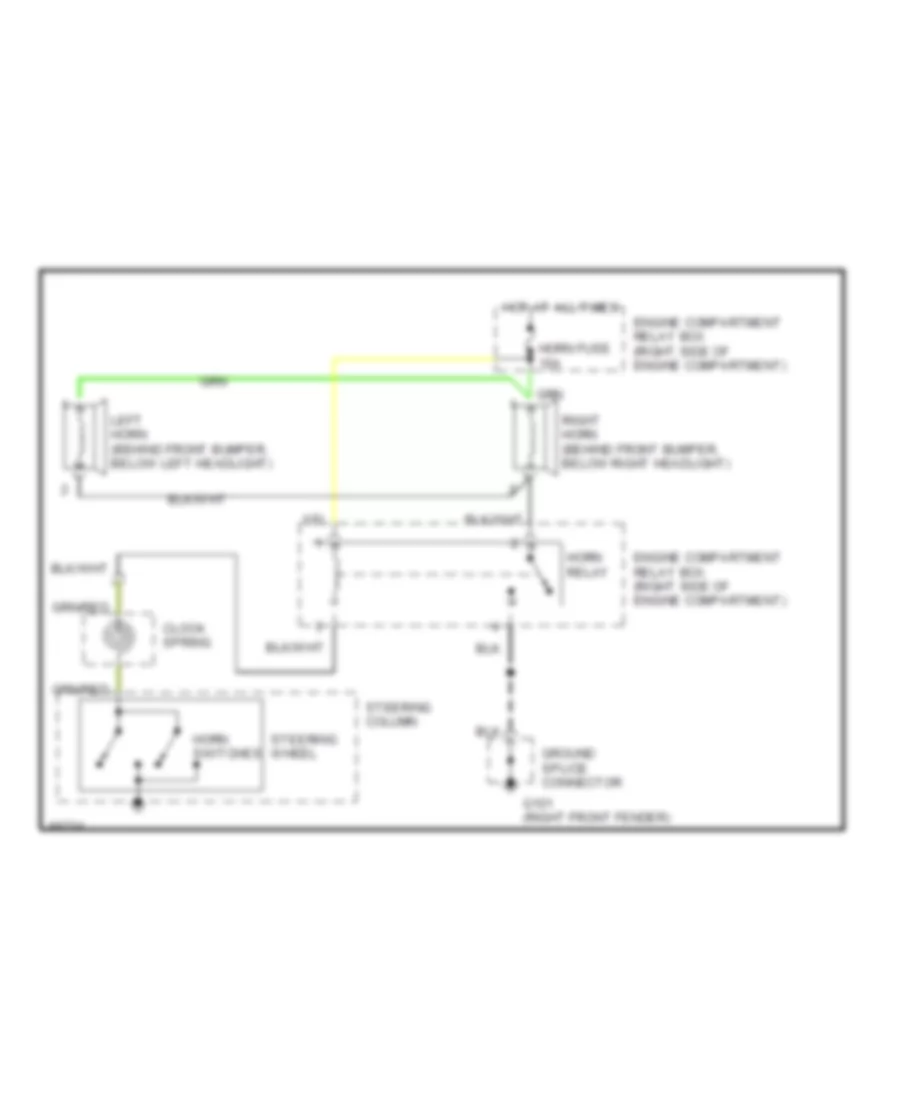
HORN
Horn Wiring Diagram for Hyundai Elantra 1995
 https://portal-diagnostov.com/license.html
Automotive Electricians Portal FZCO
Automotive Electricians Portal FZCO
https://portal-diagnostov.com/license.html
https://portal-diagnostov.com/license.html
Automotive Electricians Portal FZCO
Automotive Electricians Portal FZCOList of elements for Horn Wiring Diagram for Hyundai Elantra 1995:
- Clock spring
- Engine compartment relay box (right side of engine compartment)
- G101 (right front fender)
- Ground splice connector
- Horn fuse 10a
- Horn relay
- Horn switches
- Hot at all times
- Left horn (behind front bumper, below left headlight)
- Right horn (behind front bumper, below right headlight)
- Steering column
- Steering wheel
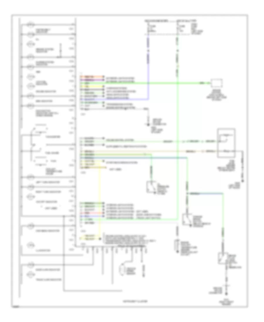
INSTRUMENT CLUSTER
Instrument Cluster Wiring Diagram for Hyundai Elantra 1995
 https://portal-diagnostov.com/license.html
Automotive Electricians Portal FZCO
Automotive Electricians Portal FZCO
https://portal-diagnostov.com/license.html
https://portal-diagnostov.com/license.html
Automotive Electricians Portal FZCO
Automotive Electricians Portal FZCOList of elements for Instrument Cluster Wiring Diagram for Hyundai Elantra 1995:
- "brake" system indicator
- "o/d off" indicator
- (door jamb switches)
- (not used)
- (trunk light switch)
- Abs
- Anti-lock brakes system
- Brake fluid level switch (in reservoir)
- Charge system indicator
- Coolant temperature gauge
- Cruise control module (pin 16, m21) data link connector (pin 11, m33) transmission control module (pin 10, e02-1) engine control module (pin 19, c01-1) (pin 18, c01-5) california
- Cruise control system
- Cruise indicator
- Dash fuse box (left side of dash)
- Door ajar indicator
- Engine control module (ecm) (behind left side of dash)
- Engine controls system
- Engine coolant temperature sender (near coolant outlet)
- Exterior lights system
- Fasten belt indicator
- Fuel gauge
- Fuel level sender (below center of rear seat)
- Fuse 10a
- Fuse 15a
- G101 (right front fender)
- G202 (left side of dash)
- G400 (left side of trunk)
- Ground splice connector
- Headlights system
- High beam indicator
- Hot at all times
- Hot in on and start
- I13-1
- I13-2
- I13-3
- I13-4
- Illumination
- Instrument cluster
- Interior lights system
- Left turn indicator
- Low fuel indicator
- Malfunction indicator lamp (mil) (check engine)
- Oil
- Oil pressure switch (near oil filter)
- Parking brake switch (below rear of console)
- Red
- Right turn indicator
- Srs indicator
- Starting/charging system
- Tachometer
- Transmissions system
- Trunk ajar indicator
- Vehicle speed sensor
- Warning systems
INTERIOR LIGHTS
Courtesy Lamps Wiring Diagram, with Sunroof for Hyundai Elantra 1995
 https://portal-diagnostov.com/license.html
Automotive Electricians Portal FZCO
Automotive Electricians Portal FZCO
https://portal-diagnostov.com/license.html
https://portal-diagnostov.com/license.html
Automotive Electricians Portal FZCO
Automotive Electricians Portal FZCOList of elements for Courtesy Lamps Wiring Diagram, with Sunroof for Hyundai Elantra 1995:
- (door ajar indicator) instrument cluster system
- 15a
- Dash fuse box (below left side of dash)
- Dome
- Etacs module (under driver's seat)
- Fuse 6
- G202 (left side of dash)
- G300 (below left front seat)
- G301 (below right front seat)
- G400 (left side of trunk)
- Gls models only
- Ground splice connector
- Hot at all times
- Instrument cluster system (trunk ajar indicator)
- Left door courtesy light
- Left front door jamb switch (in lower rear of driver's door jamb)
- Left rear door jamb switch (in center rear of left rear door jamb)
- Map
- Nca
- Off
- Overhead console assembly
- Power distribution
- Right door courtesy light
- Right front door jamb switch (in lower rear of passenger's door jamb)
- Right rear door jamb switch (in center rear of right rear door jamb)
- Trunk light
- Trunk light switch (center rear of trunk)
Courtesy Lamps Wiring Diagram, without Sunroof for Hyundai Elantra 1995
 https://portal-diagnostov.com/license.html
Automotive Electricians Portal FZCO
Automotive Electricians Portal FZCO
https://portal-diagnostov.com/license.html
https://portal-diagnostov.com/license.html
Automotive Electricians Portal FZCO
Automotive Electricians Portal FZCOList of elements for Courtesy Lamps Wiring Diagram, without Sunroof for Hyundai Elantra 1995:
- (door ajar indicator) instrument cluster system
- 15a
- Dash fuse box (below left side of dash)
- Dome light
- Etacs module (under driver's seat)
- Fuse 6
- G202 (left side of dash)
- G300 (below left front seat)
- G301 (below right front seat)
- G400 (left side of trunk)
- Gls
- Gls models only
- Ground splice connector
- Hot at all times
- Instrument cluster system (trunk ajar indicator)
- Left door courtesy light
- Left front door jamb switch (in lower rear of driver's door jamb)
- Left rear door jamb switch (in center rear of left rear door jamb)
- Map lights
- Nca
- Off
- Power distribution
- Right door courtesy light
- Right front door jamb switch (in lower rear of passenger's door jamb)
- Right rear door jamb switch (in center rear of right rear door jamb)
- Trunk light
- Trunk light switch (center rear of trunk)
Instrument Illumination Wiring Diagram for Hyundai Elantra 1995
 https://portal-diagnostov.com/license.html
Automotive Electricians Portal FZCO
Automotive Electricians Portal FZCO
https://portal-diagnostov.com/license.html
https://portal-diagnostov.com/license.html
Automotive Electricians Portal FZCO
Automotive Electricians Portal FZCOList of elements for Instrument Illumination Wiring Diagram for Hyundai Elantra 1995:
- A/c switch
- A/t only
- Ashtray light
- Cigarette lighter
- Cruise control switch
- Dash fuse box (below left side of dash)
- Dim input
- Driver's master switch assembly (power window system)
- Fuse 16 10a
- Fuse 17 10a
- G201 (right side of dash)
- G202 (left side of dash)
- G300 (below left front seat)
- G301 (below right front seat)
- Gls models only
- Ground splice connector
- Hazard switch
- Heater and a/c control panel
- Hot with light switch in park or head
- Illumination
- Illumination (7)
- Illumination input
- Instrument cluster
- Left rear power window switch
- Nca
- Passenger compartment relay center (behind left side of dash)
- Passenger power window switch
- Radio
- Rear window defogger switch
- Recirculate switch illumination
- Rheostat
- Right rear power window switch
- Shifter illumination
- Solid state
PASSIVE RESTRAINTS
Seat Belt Release Wiring Diagram for Hyundai Elantra 1995
 https://portal-diagnostov.com/license.html
Automotive Electricians Portal FZCO
Automotive Electricians Portal FZCO
https://portal-diagnostov.com/license.html
https://portal-diagnostov.com/license.html
Automotive Electricians Portal FZCO
Automotive Electricians Portal FZCOList of elements for Seat Belt Release Wiring Diagram for Hyundai Elantra 1995:
- (below left g300
- (below right g301
- (gls model)
- (rear of passenger's door)
- (right side g201
- Battery
- Chime control
- Chime module (left side of dash)
- Dash fuse box (left side of dash)
- Door open input
- Door)
- Electronic time and alarm control module (below drivers seat)
- Fasten belt indicator
- Fault input
- Front seat)
- Fuse 10 10a
- Fuse 19 10a
- Fuse 7 20a
- Fuse 8 10a
- Gls models only
- Ground
- Grounds
- Hot at all times
- Hot in on and start
- I13-1
- Ignition
- Ignition and start input
- Ignition key switch
- Indicator control
- Instrument cluster
- Interior lights system
- Left front door open input
- Left front door jamb switch (in lower rear of driver's door jamb)
- Locking ball
- Micro switch
- Of dash)
- Passenger's door)
- Passive restraint control module (bottom of right "b" pillar)
- Passive seat belt input
- Passive seat belt switch (under driver's
- Red
- Right door latch switch (rear of passenger's
- Right lap retractor (rear of
- Right shoulder retractor
- Seat, in seat belt buckle)
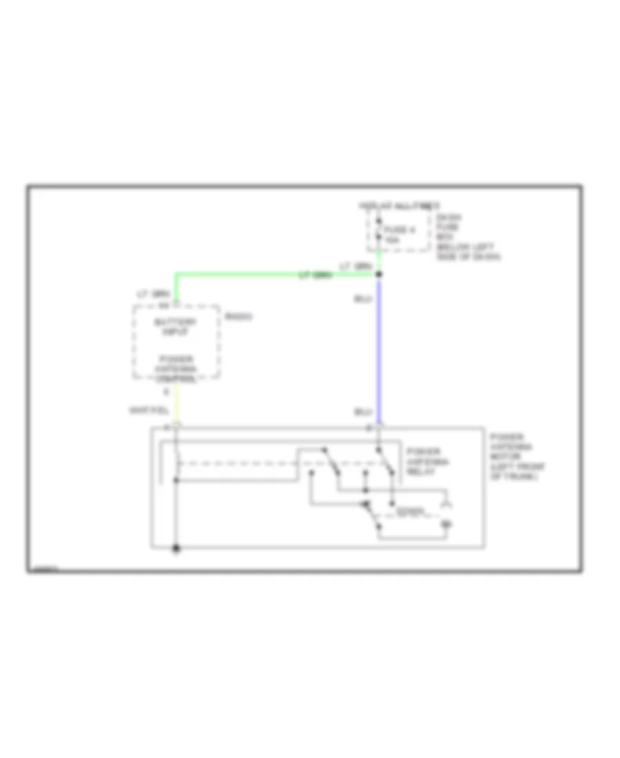
POWER ANTENNA
Power Antenna Wiring Diagram for Hyundai Elantra 1995
 https://portal-diagnostov.com/license.html
Automotive Electricians Portal FZCO
Automotive Electricians Portal FZCO
https://portal-diagnostov.com/license.html
https://portal-diagnostov.com/license.html
Automotive Electricians Portal FZCO
Automotive Electricians Portal FZCOList of elements for Power Antenna Wiring Diagram for Hyundai Elantra 1995:
- Battery input
- Dash fuse box (below left side of dash)
- Down
- Fuse 4 10a
- Hot at all times
- Power antenna control
- Power antenna motor (left front of trunk)
- Power antenna relay
- Radio
POWER DISTRIBUTION
Power Distribution Wiring Diagram (1 of 5) for Hyundai Elantra 1995
 https://portal-diagnostov.com/license.html
Automotive Electricians Portal FZCO
Automotive Electricians Portal FZCO
https://portal-diagnostov.com/license.html
https://portal-diagnostov.com/license.html
Automotive Electricians Portal FZCO
Automotive Electricians Portal FZCOList of elements for Power Distribution Wiring Diagram (1 of 5) for Hyundai Elantra 1995:
- (w/ power window only)
- A/c control relay
- A/c switch
- A/con 1 fuse 10a
- A/con 2 fuse 10a
- Abs fusible link 30a (pnk)
- Abs pump motor relay
- Abs relay box
- Batt fusible link 50a (red)
- Battery
- Blower fuse 30a
- Blower motor
- Blower relay
- C02
- Condenser fan motor relay
- E04
- E05
- E07
- E08
- E18
- E38
- E57
- E72-1
- E72-2
- Ecm control relay
- Engine compartment relay box
- Engine coolant fan a/c on relay
- Engine coolant fan motor relay
- Fail safe ralay
- G101 (right front corner of engine compartment)
- Generator
- Horn fuse 10a
- Horn relay
- I10
- Ign sw fusible link 30a (pnk)
- Left horn
- M17
- M19
- Main fusible link box
- Nca
- P/wdw fusible link 30a (pnk)
- Passenger compartment relay center
- Power window relay
- Red
- Right horn
- Starter solenoid
- To fuse (diagram 2 of 5)
- To h/lamp fuse (diagram 3 of 5)
- To ignition swich (diagram 4 of 5)
- Transmission
Power Distribution Wiring Diagram (2 of 5) for Hyundai Elantra 1995
 https://portal-diagnostov.com/license.html
Automotive Electricians Portal FZCO
Automotive Electricians Portal FZCO
https://portal-diagnostov.com/license.html
https://portal-diagnostov.com/license.html
Automotive Electricians Portal FZCO
Automotive Electricians Portal FZCOList of elements for Power Distribution Wiring Diagram (2 of 5) for Hyundai Elantra 1995:
- (a/t only)
- (california only)
- (not used)
- A/t
- Ashtray light park/ turn light
- Brake pedal switch
- C01-5 c01-3
- Central door locking actuator
- Cigarette lighter light
- D06
- D21
- Dash fuse box
- Digital clock
- E02-1
- Electronic time & alarm control module
- Engine compartment relay box
- Engine control module
- From fuse 17 (diagram 3 of 5)
- From fusible link batt (diagram 1 of 5)
- Fuse 19 10a
- Fuse 2 10a
- Fuse 3 15a
- Fuse 4 10a
- Fuse 5 15a
- Fuse 7 20a
- Fuse 8 10a
- Gl model
- Gls model
- Hazard switch
- I09
- I11
- Ignition switch
- Key lock solenoid
- M/t
- M23
- M25
- M28 m27
- M38
- M43
- M48
- M58
- M65
- Passenger compartment relay center
- Passive restraint control module
- Power antenna motor
- Radio
- Red
- Right front park/ turn light
- Right license light
- Right tail/ stop light
- Shift lock solenoid
- To fuse 6 (diagram 3 of 5)
- Transmission control module
- Trunk release switch
- W/ power antenna
- W/o power antenna
Power Distribution Wiring Diagram (3 of 5) for Hyundai Elantra 1995
 https://portal-diagnostov.com/license.html
Automotive Electricians Portal FZCO
Automotive Electricians Portal FZCO
https://portal-diagnostov.com/license.html
https://portal-diagnostov.com/license.html
Automotive Electricians Portal FZCO
Automotive Electricians Portal FZCOList of elements for Power Distribution Wiring Diagram (3 of 5) for Hyundai Elantra 1995:
- (a/t only)
- (diagram 1 of 5)
- (gls models only)
- (not used)
- 10a
- 2 of 5)
- A/c switch
- Cruise control switch
- D10
- D20
- Dash fuse box
- Dome light
- Driver's master switch assembly (gls only)
- Drl control module
- E23
- E31-2
- E36
- E40
- Engine compartment relay box
- From fuse 8, (diagram d
- From fusible link lamp a
- Fuse 16
- Fuse 17
- Fuse 6 15a
- Generator
- Gl models
- Gls models w/ sunroof
- Gls models w/o sunroof
- H/l ind fuse
- H/lamp fuse 20a
- Hazard switch motor
- Headlight relay
- Heater-a/c control panel
- I13-1
- I13-3
- Illumination
- Instrument cluster
- Left door courtesy light
- Left front park/turn light
- Left headlight
- Left license light
- Left rear power window switch (gls only)
- Left tail/ stop light
- M55
- M71
- M73
- M76
- M77
- Map lights
- Overhead console assembly
- Passenger compartment relay center
- Radio
- Rear defogger switch
- Recirc switch illumination
- Rheostat
- Right door courtesy light
- Right headlight
- Right rear power window switch (gls only)
- Shifter illumi- nation
- Sunroof close/tilt up relay
- Sunroof open/tilt down relay
- Taillight relay
- To passenger compartment relay center (diagram 2 of 5)
- Trunk light
- W/ drl
- W/o drl
Power Distribution Wiring Diagram (4 of 5) for Hyundai Elantra 1995
 https://portal-diagnostov.com/license.html
Automotive Electricians Portal FZCO
Automotive Electricians Portal FZCO
https://portal-diagnostov.com/license.html
https://portal-diagnostov.com/license.html
Automotive Electricians Portal FZCO
Automotive Electricians Portal FZCOList of elements for Power Distribution Wiring Diagram (4 of 5) for Hyundai Elantra 1995:
- (a/t only)
- (california only)
- (diagram 1 of 5)
- (gls models only)
- (not used)
- (w/ cruise only)
- A/t
- Acc
- Back up light switch
- C01-3
- C01-5
- C02
- C07
- C14
- Cruise control module
- Cruise control switch
- Dash fuse box
- E27
- E28
- Ecm control relay
- Electronic time & alarm control module
- Engine control module (ecm)
- From fusible link ign sw c
- Fuse 1 10a
- Fuse 10 10a
- Fuse 18 10a
- Fuse 9 10a
- Hazard switch
- I07
- I09
- I13-1
- Ig1
- Ig2
- Ignition coil assembly
- Ignition switch
- Instrument cluster
- Lock
- M/t
- M15
- M21
- M24
- M29
- M35
- M38
- M48
- M81
- Nca
- Passenger compartment relay center
- Passive restraint control module
- Pre- excitation resistor
- Red
- Srs control module
- Start
- Starter clutch pedal position switch
- Starter relay
- To dash fuse box (diagram 5 of 5)
- Transmission & key lock control module
- Transmission range switch
Power Distribution Wiring Diagram (5 of 5) for Hyundai Elantra 1995
 https://portal-diagnostov.com/license.html
Automotive Electricians Portal FZCO
Automotive Electricians Portal FZCO
https://portal-diagnostov.com/license.html
https://portal-diagnostov.com/license.html
Automotive Electricians Portal FZCO
Automotive Electricians Portal FZCOList of elements for Power Distribution Wiring Diagram (5 of 5) for Hyundai Elantra 1995:
- (gls model only)
- (gls w/ sunroof only)
- (w/ cruise only)
- Abs relay box
- Anti-lock brake control module
- Blower relay
- Cigarette lighter
- Cruise control module
- Dash fuse box
- Digital clock
- E02-3
- E06
- E16
- E26
- E28
- E37
- E72-1
- Electronic time & alarm control module
- Engine compartment relay box
- Engine coolant temperature switch b
- Fail safe relay
- From ignition e switch (diagram 4 of 5)
- From ignition f switch (diagram 4 of 5)
- Fuse 11 15a
- Fuse 12 10a
- Fuse 13 15a
- Fuse 14 10a
- Fuse 15 15a
- G202
- Ground splice connector (left side of dash)
- Headlight relay
- Heater-a/c control panel
- I11
- M17
- M19
- M21
- M24
- M38
- M41
- M42
- M43
- M44
- M60
- M62-2
- M62-3
- M76
- M77
- M93
- Overdrive switch
- Passenger compartment relay center
- Power mirror switch
- Power window relay
- Radio
- Red
- Sunroof close/tilt up relay
- Sunroof open/tilt down relay
- Transmission & key lock control module
- Transmission control module
- Transmission range switch
- Transmission shift mode switch
- Washer motor
- Wiper motor
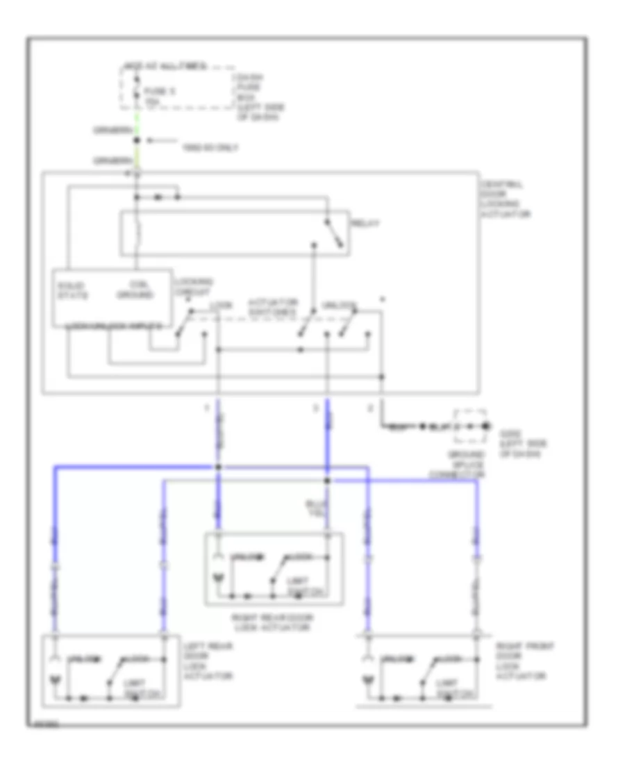
POWER DOOR LOCKS
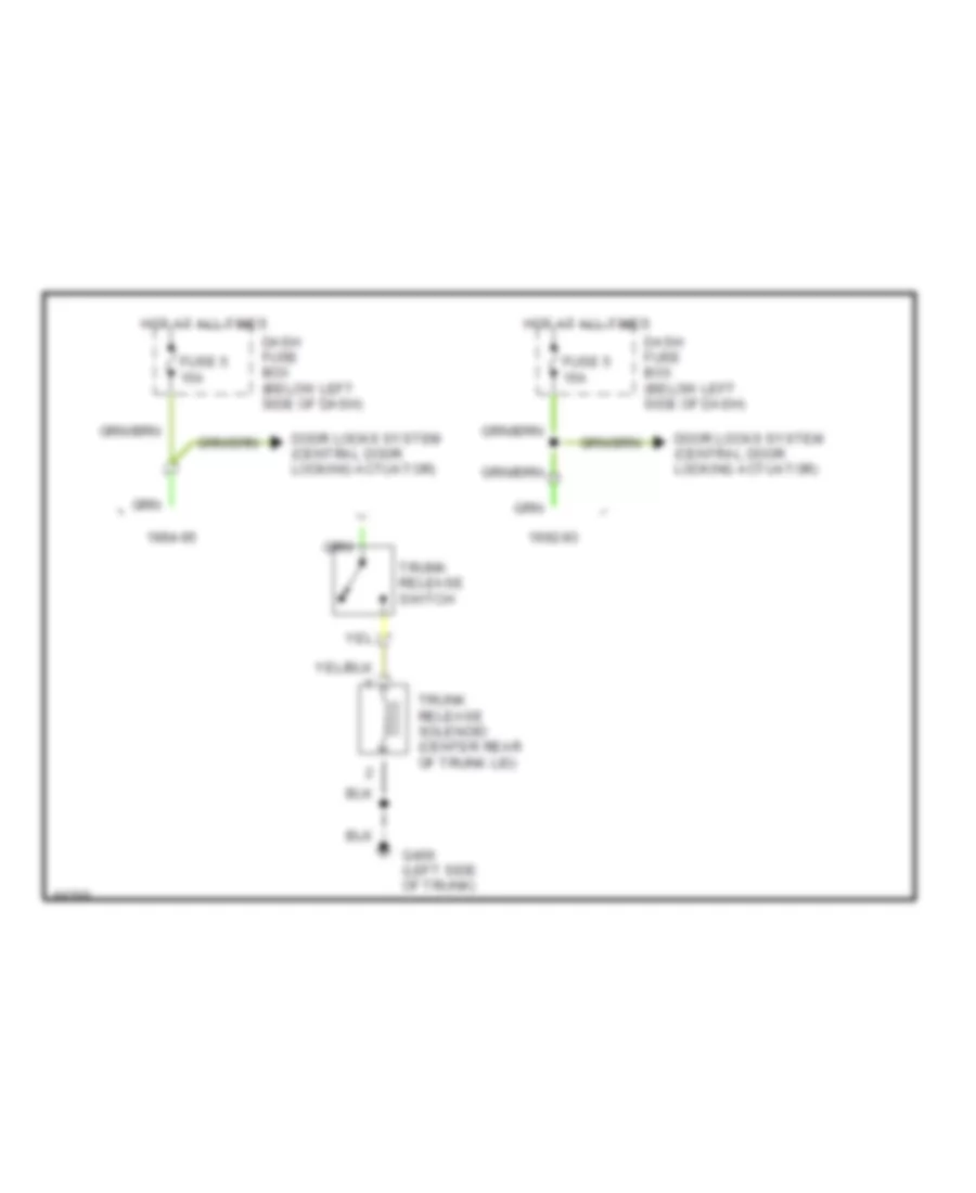
Power Door Lock Wiring Diagram for Hyundai Elantra 1995
 https://portal-diagnostov.com/license.html
Automotive Electricians Portal FZCO
Automotive Electricians Portal FZCO
https://portal-diagnostov.com/license.html
https://portal-diagnostov.com/license.html
Automotive Electricians Portal FZCO
Automotive Electricians Portal FZCOList of elements for Power Door Lock Wiring Diagram for Hyundai Elantra 1995:
- 1992-93 only
- Actuator switches
- Central door locking actuator
- Coil ground
- Dash fuse box (left side of dash)
- Fuse 5 15a
- G202 (left side of dash)
- Ground splice connector
- Hot at all times
- Left rear door lock actuator
- Limit switch
- Lock
- Lock/unlock inputs
- Locking circuit
- Relay
- Right front door lock actuator
- Right rear door lock actuator
- Solid state
- Unlock
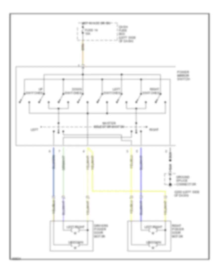
POWER MIRRORS
Power Mirror Wiring Diagram for Hyundai Elantra 1995
 https://portal-diagnostov.com/license.html
Automotive Electricians Portal FZCO
Automotive Electricians Portal FZCO
https://portal-diagnostov.com/license.html
https://portal-diagnostov.com/license.html
Automotive Electricians Portal FZCO
Automotive Electricians Portal FZCOList of elements for Power Mirror Wiring Diagram for Hyundai Elantra 1995:
- (left side g202
- Dash fuse box (left side of dash)
- Down switches
- Drivers power door motor
- Fuse 14 10a
- Ground splice connector
- Hot in acc or on
- Left
- Left switches
- Left/right
- Master selector switch
- Of dash)
- Power mirror switch
- Right
- Right power door motor
- Right switches
- Up switches
- Up/down
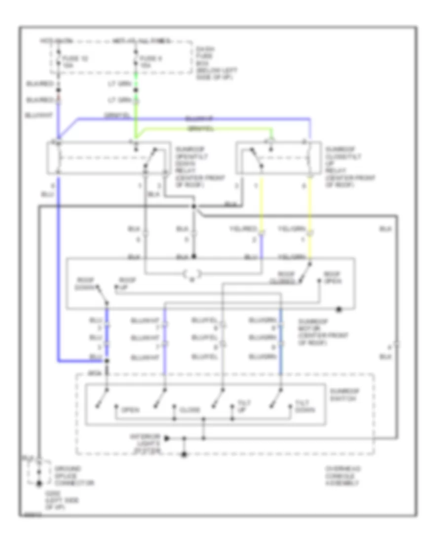
POWER TOP/SUNROOF
Power Top/Sunroof Wiring Diagrams for Hyundai Elantra 1995
 https://portal-diagnostov.com/license.html
Automotive Electricians Portal FZCO
Automotive Electricians Portal FZCO
https://portal-diagnostov.com/license.html
https://portal-diagnostov.com/license.html
Automotive Electricians Portal FZCO
Automotive Electricians Portal FZCOList of elements for Power Top/Sunroof Wiring Diagrams for Hyundai Elantra 1995:
- Close
- Dash fuse box (below left side of i/p)
- Fuse 12 10a
- Fuse 6 15a
- G202 (left side of i/p)
- Ground splice connector
- Hot at all times
- Hot in on
- Interior lights system
- Nca
- Open
- Overhead console assembly
- Roof open
- Roof up
- Roof closed
- Roof down
- Sunroof close/tilt up relay (center front of roof)
- Sunroof motor (center front of roof)
- Sunroof open/tilt down relay (center front of roof)
- Sunroof switch
- Tilt down
- Tilt up
POWER WINDOWS
Power Window Wiring Diagram for Hyundai Elantra 1995
 https://portal-diagnostov.com/license.html
Automotive Electricians Portal FZCO
Automotive Electricians Portal FZCO
https://portal-diagnostov.com/license.html
https://portal-diagnostov.com/license.html
Automotive Electricians Portal FZCO
Automotive Electricians Portal FZCOList of elements for Power Window Wiring Diagram for Hyundai Elantra 1995:
- 10a
- 30a (pnk)
- Dash fuse box (left side of dash)
- Down
- Driver power window motor
- Driver's master switch assembly
- Engine compartment relay box (right side of engine compartment)
- Fuse 12
- Fusible link (p/wdo)
- G202 (left side of dash)
- Ground splice connector
- Hot at all times
- Hot in run
- Interior lights system
- Led
- Left front window switch
- Left rear power window motor
- Left rear power window switch
- Left rear window switch
- Lockout switch
- Off
- Off down
- Passenger compartment relay center (left side of dash)
- Passenger power window switch
- Power window relay
- Right front power window motor
- Right front window switch
- Right rear power window motor
- Right rear power window switch
- Right rear window switch
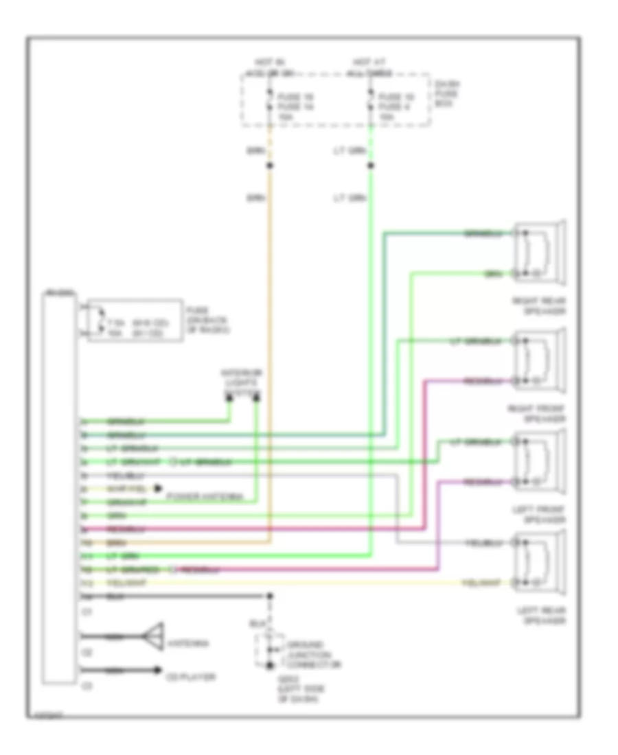
RADIO
Radio Wiring Diagrams for Hyundai Elantra 1995
 https://portal-diagnostov.com/license.html
Automotive Electricians Portal FZCO
Automotive Electricians Portal FZCO
https://portal-diagnostov.com/license.html
https://portal-diagnostov.com/license.html
Automotive Electricians Portal FZCO
Automotive Electricians Portal FZCOList of elements for Radio Wiring Diagrams for Hyundai Elantra 1995:
- (w/0 cd) (w/ cd)
- 7.5a 10a
- Acc or on
- All times
- Antenna
- Cd player
- Dash fuse box
- Fuse (on back of radio)
- Fuse 10 fuse 4 10a
- Fuse 19 fuse 14 10a
- G202 (left side of dash)
- Ground junction connector
- Hot at
- Hot in
- Interior lights system
- Left front speaker
- Left rear speaker
- Nca
- Power antenna
- Radio
- Right front speaker
- Right rear speaker
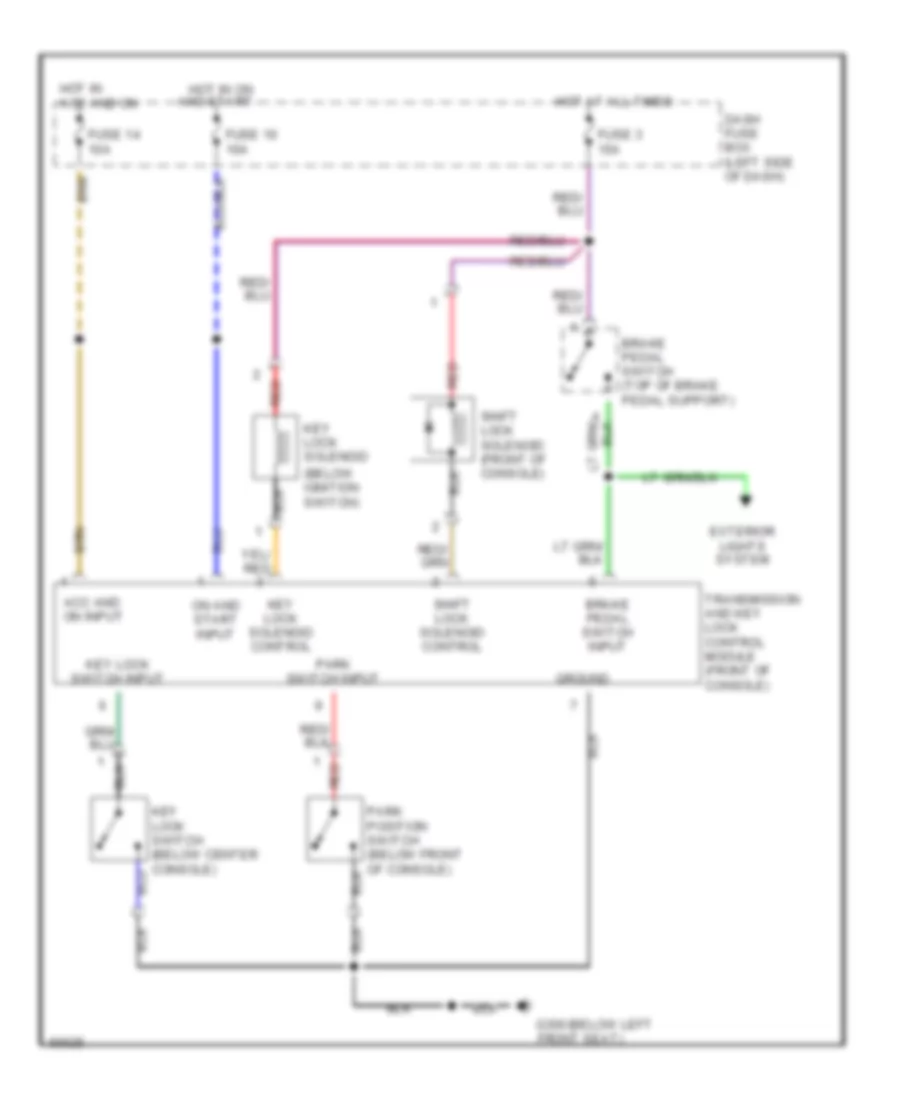
SHIFT INTERLOCKS
Shift Interlock Wiring Diagram for Hyundai Elantra 1995
 https://portal-diagnostov.com/license.html
Automotive Electricians Portal FZCO
Automotive Electricians Portal FZCO
https://portal-diagnostov.com/license.html
https://portal-diagnostov.com/license.html
Automotive Electricians Portal FZCO
Automotive Electricians Portal FZCOList of elements for Shift Interlock Wiring Diagram for Hyundai Elantra 1995:
- (below ignition switch)
- Acc and on input
- Brake pedal switch (top of brake pedal support)
- Brake pedal switch input
- Dash fuse box (left side of dash)
- Exterior lights system
- Front seat)
- Fuse 10 10a
- Fuse 14 10a
- Fuse 3 15a
- G300 (below left
- Ground
- Hot at all times
- Hot in acc and on
- Hot in on and start
- Key lock solenoid
- Key lock solenoid control
- Key lock switch (below center console)
- Key lock switch input
- On and start input
- Park position switch (below front of console)
- Park switch input
- Red
- Shift lock solenoid (front of console)
- Shift lock solenoid control
- Transmission and key lock control module (front of console)
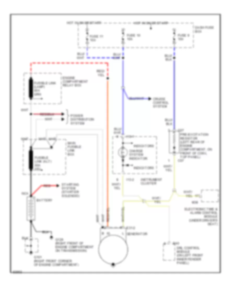
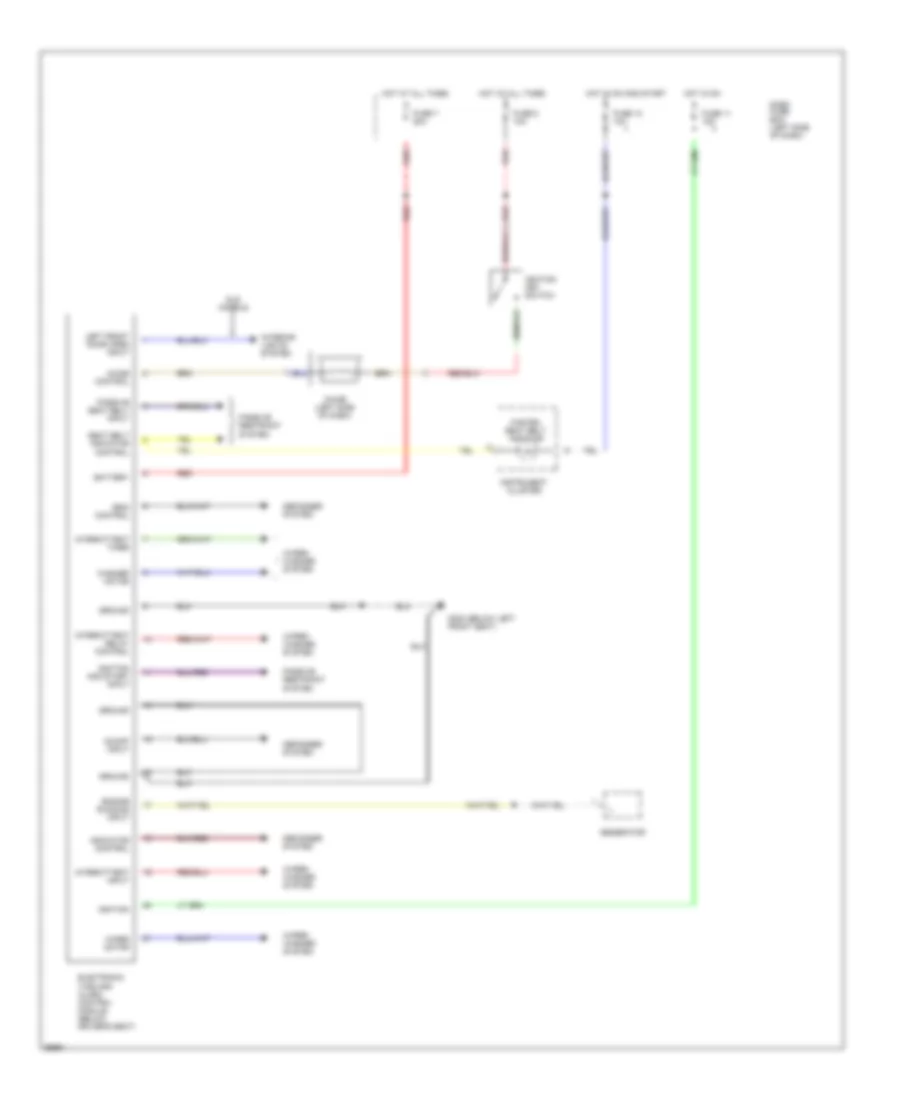
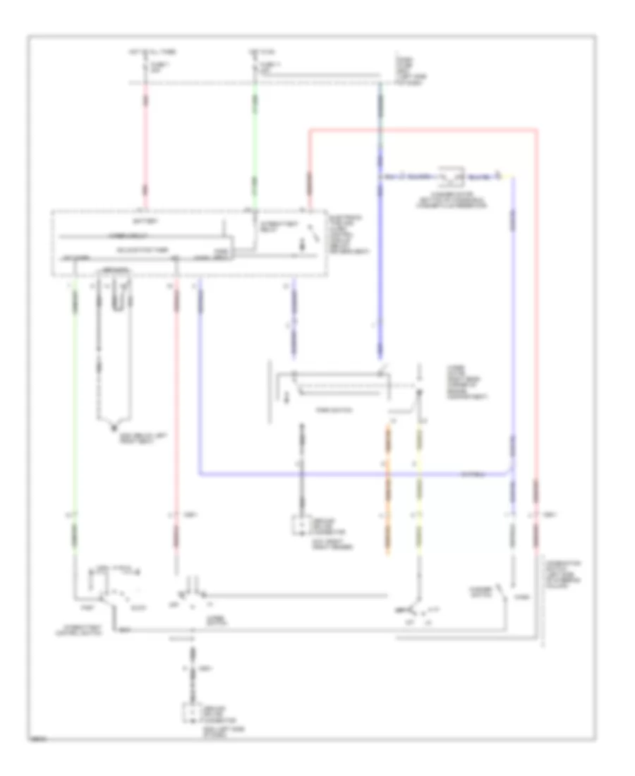
STARTING/CHARGING
Charging Wiring Diagram for Hyundai Elantra 1995
 https://portal-diagnostov.com/license.html
Automotive Electricians Portal FZCO
Automotive Electricians Portal FZCO
https://portal-diagnostov.com/license.html
https://portal-diagnostov.com/license.html
Automotive Electricians Portal FZCO
Automotive Electricians Portal FZCOList of elements for Charging Wiring Diagram for Hyundai Elantra 1995:
- Battery
- C07
- Charge system indicator
- Cruise control system
- Dash fuse box
- Drl control module (on left front inner fender panel)
- E31-2
- E40
- Electronic time & alarm control module (under driver's seat)
- Engine compartment relay box
- Fuse 10 10a
- Fuse 11 10a
- Fuse 9 10a
- G101 (right front corner of engine compartment)
- G129 (right front of engine compartment on transmission)
- Generator
- Hot in on or start
- I13-1
- I13-2
- Indicators
- Instrument cluster
- M38
- Main fusible link box
- Nca
- Power distribution system
- Pre-excitation resistor (left rear of engine compartment, on front of cowl top panel)
- Red
- Starting system (starter solenoid)
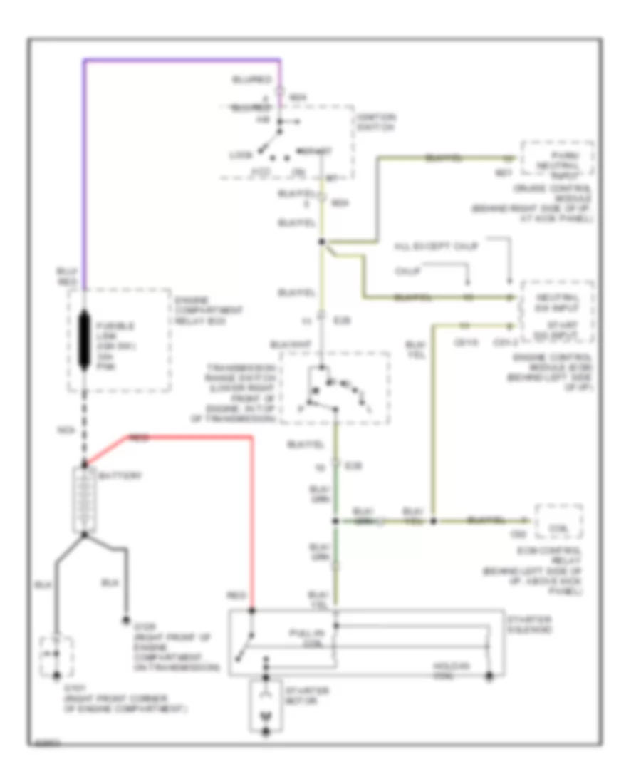
Starting Wiring Diagram, A/T for Hyundai Elantra 1995
 https://portal-diagnostov.com/license.html
Automotive Electricians Portal FZCO
Automotive Electricians Portal FZCO
https://portal-diagnostov.com/license.html
https://portal-diagnostov.com/license.html
Automotive Electricians Portal FZCO
Automotive Electricians Portal FZCOList of elements for Starting Wiring Diagram, A/T for Hyundai Elantra 1995:
- Acc
- All except calif
- Battery
- C01-3
- C01-5
- C02
- Calif
- Coil
- Cruise control module (behind right side of i/p, at kick panel)
- E28
- Ecm control relay (behind left side of i/p, above kick panel)
- Engine compartment relay box
- Engine control module (ecm) (behind left side of i/p)
- Fusible link (ign sw) 30a pnk
- G101 (right front corner of engine compartment)
- G129 (right front of engine compartment, on transmission)
- Hold-in coil
- Ignition switch
- Lock
- M21
- M24
- N d
- Nca
- Neutral sw input
- Park/ neutral input
- Pull-in coil
- Red
- Start
- Start sig input
- Starter motor
- Starter solenoid
- Transmission range switch (lower right front of engine, in top of transmission)
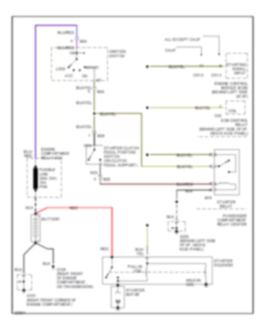
Starting Wiring Diagram, M/T for Hyundai Elantra 1995
 https://portal-diagnostov.com/license.html
Automotive Electricians Portal FZCO
Automotive Electricians Portal FZCO
https://portal-diagnostov.com/license.html
https://portal-diagnostov.com/license.html
Automotive Electricians Portal FZCO
Automotive Electricians Portal FZCOList of elements for Starting Wiring Diagram, M/T for Hyundai Elantra 1995:
- Acc
- All except calif
- Battery
- C01-3
- C01-5
- C02
- Calif
- Coil
- Ecm control relay (behind left side of i/p, above kick panel)
- Engine compartment relay box
- Engine control module (ecm) (behind left side of i/p)
- Fusible link (ign. sw) 30a pnk
- G101 (right front corner of engine compartment)
- G129 (right front of engine compartment, on transmission)
- G202 (behind left side of i/p, above kick panel)
- Hold-in coil
- Ignition switch
- Lock
- M15
- M24
- M29
- Nca
- Passenger compartment relay center
- Pull-in coil
- Red
- Start
- Starter clutch pedal position switch (on clutch pedal support)
- Starter motor
- Starter relay
- Starter solenoid
- Starting signal input
SUPPLEMENTAL RESTRAINTS
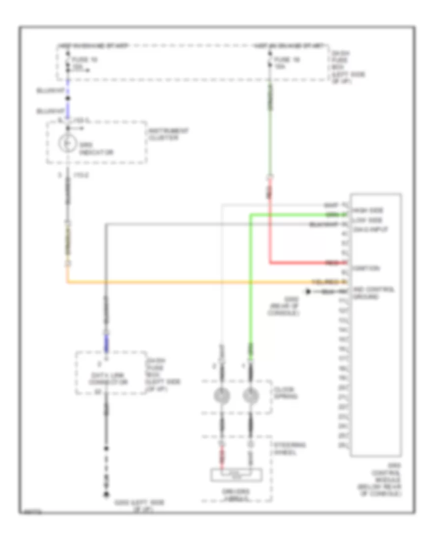
Supplemental Restraint Wiring Diagram for Hyundai Elantra 1995
 https://portal-diagnostov.com/license.html
Automotive Electricians Portal FZCO
Automotive Electricians Portal FZCO
https://portal-diagnostov.com/license.html
https://portal-diagnostov.com/license.html
Automotive Electricians Portal FZCO
Automotive Electricians Portal FZCOList of elements for Supplemental Restraint Wiring Diagram for Hyundai Elantra 1995:
- (left side g202
- Clock spring
- Dash fuse box (left side of i/p)
- Data link connector
- Diag input
- Drivers airbag
- Fuse 10 10a
- Fuse 18 10a
- G302 (rear of console)
- High side
- Hot in on and start
- I13-1
- I13-2
- Ignition
- Ind control ground
- Instrument cluster
- Low side
- Nca
- Of i/p)
- Red
- Srs control module (below rear of console)
- Srs indicator
- Steering wheel
TRANSMISSION
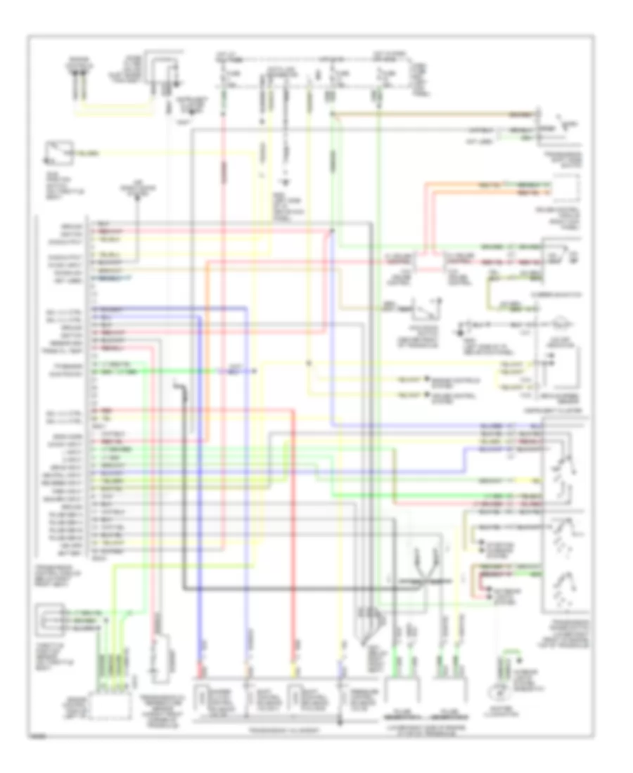
Transmission Wiring Diagram for Hyundai Elantra 1995
 https://portal-diagnostov.com/license.html
Automotive Electricians Portal FZCO
Automotive Electricians Portal FZCO
https://portal-diagnostov.com/license.html
https://portal-diagnostov.com/license.html
Automotive Electricians Portal FZCO
Automotive Electricians Portal FZCOList of elements for Transmission Wiring Diagram for Hyundai Elantra 1995:
- (lower right front of engine, top of transaxle)
- (lower right side of engine, in top of transaxle)
- (not used)
- (right kick panel)
- 2 input
- A/c sw input
- Air conditioning system
- Battery
- C01-5
- Cruise control module
- Cruise control system
- Damper clutch control solenoid valve
- Dash fuse box (left kick panel)
- Data link connector
- Diag output
- Drive input
- Econ
- Econ mode
- Eng rpm input
- Engine control module (left i/p)
- Engine controls system
- Eo2-1
- Eo2-2
- Exterior lights system
- Fuse 10a
- Fuse 15a
- G200 (left side of i/p, above kick panel)
- G301 (below right front seat)
- Ground
- Hot at all times
- Hot in on
- Hot in park or head
- I13-1
- I13-2
- I13-4
- Idle pos sw
- Idle position switch (on throttle body)
- Ignition
- Instrument cluster
- Instrument cluster system
- Interior lights system (rheostat)
- Kick down switch (center front of transaxle)
- Kickdn sw
- L input
- M33
- Nca
- Neutral input
- Noise filter (on air inlet surge tank assy)
- Norm
- Not used
- O/d off
- O/d off indicator
- O/d on
- O/d sw input
- Overdrive switch
- Park input
- Pressure control solenoid valve
- Pulse gen a
- Pulse gen b
- Pulse generator a
- Pulse generator b
- Red
- Reverse input
- Sensor gnd
- Shift control solenoid valve a
- Shift control solenoid valve b
- Shifter illumination
- Sol vlv ctrl
- Starting/ charging system
- Throttle position sensor (on throttle body)
- Tp sensor
- Trans oil temp
- Transmission control module (below right front seat)
- Transmission oil temperature sensor (in right front corner of transaxle)
- Transmission range switch
- Transmission shift mode switch
- Transmission valve body
- Veh spd
- Vehicle speed sensor
- W/ cruise control
- W/o cruise control
TRUNK, TAILGATE, FUEL DOOR
Trunk Release Wiring Diagram for Hyundai Elantra 1995
 https://portal-diagnostov.com/license.html
Automotive Electricians Portal FZCO
Automotive Electricians Portal FZCO
https://portal-diagnostov.com/license.html
https://portal-diagnostov.com/license.html
Automotive Electricians Portal FZCO
Automotive Electricians Portal FZCOList of elements for Trunk Release Wiring Diagram for Hyundai Elantra 1995:
- 1992-93
- 1994-95
- Dash fuse box (below left side of dash)
- Door locks system (central door locking actuator)
- Fuse 5 15a
- G400 (left side of trunk)
- Hot at all times
- Trunk release solenoid (center rear of trunk lid)
- Trunk release switch
WARNING SYSTEMS
Warning System Wiring Diagrams for Hyundai Elantra 1995
 https://portal-diagnostov.com/license.html
Automotive Electricians Portal FZCO
Automotive Electricians Portal FZCO
https://portal-diagnostov.com/license.html
https://portal-diagnostov.com/license.html
Automotive Electricians Portal FZCO
Automotive Electricians Portal FZCOList of elements for Warning System Wiring Diagrams for Hyundai Elantra 1995:
- (below left g300
- Battery
- Chime (left side of dash)
- Chime control
- Dash fuse box (left side of dash)
- Defogger system
- Electronic time and alarm control module (below driver's seat)
- Engine running input
- Fasten seat belt indictor
- Front seat)
- Fuse 10 10a
- Fuse 11 15a
- Fuse 7 20a
- Fuse 8 10a
- Generator
- Gls models
- Grid control
- Ground
- Hot at all times
- Hot in on
- Hot in on and start
- Ignition
- Ignition and start input
- Ignition key switch
- Indicator control
- Instrument cluster
- Interior lights system
- Intermittent input
- Intermittent relay control
- Intermittent timer
- Left front door open input
- On/off input
- Passive restraint system
- Passive seat belt input
- Red
- Seat belt indicator control
- Washer motor
- Wiper motor
- Wiper/ washer system
WIPER/WASHER
Wiper/Washer Wiring Diagram for Hyundai Elantra 1995
 https://portal-diagnostov.com/license.html
Automotive Electricians Portal FZCO
Automotive Electricians Portal FZCO
https://portal-diagnostov.com/license.html
https://portal-diagnostov.com/license.html
Automotive Electricians Portal FZCO
Automotive Electricians Portal FZCOList of elements for Wiper/Washer Wiring Diagram for Hyundai Elantra 1995:
- (below left g300
- (left side g202
- (right g101
- Battery
- Combination switch (left side of steering column)
- Dash fuse box (left side of dash)
- Electronic time and alarm control module (below driver's seat)
- Fast
- Front fender)
- Front seat)
- Fuse 11 15a
- Fuse 7 20a
- Ground splice connector
- Grounds
- Hot at all times
- Hot in on
- Int
- Int
- Int timer
- Intermittent control switch
- Intermittent relay
- M26-1
- Of dash)
- Off
- Park input
- Park switch
- Red
- Slow
- Solid-state timer
- Wash
- Washer motor (bottom of windshield washer fluid reservoir)
- Washer switch
- Wiper circuit
- Wiper motor (right rear corner of engine compartment)
- Wiper switch

 Čeština
 Dansk
Dansk Deutsch
 Ελληνικά
 English
 English
 Español
 Suomi
Suomi Français
 Français
 עברית
עברית Hrvatski
 Magyar
 Italiano
 日本語
日本語 한국어
한국어 Nederlands
 Polski
 Português
 Português
 Română
 Русский
 Slovenčina
 Slovenščina
 Svenska
 中文 (中国)
