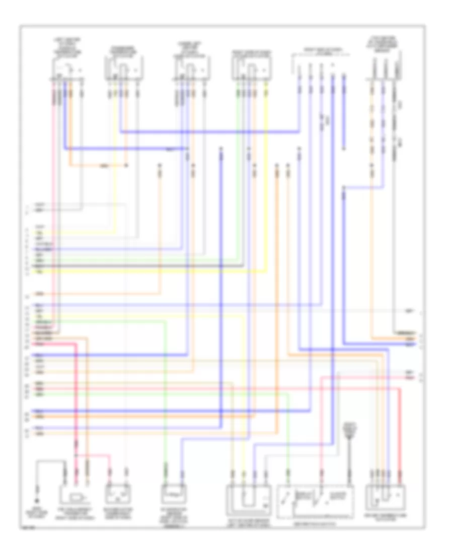
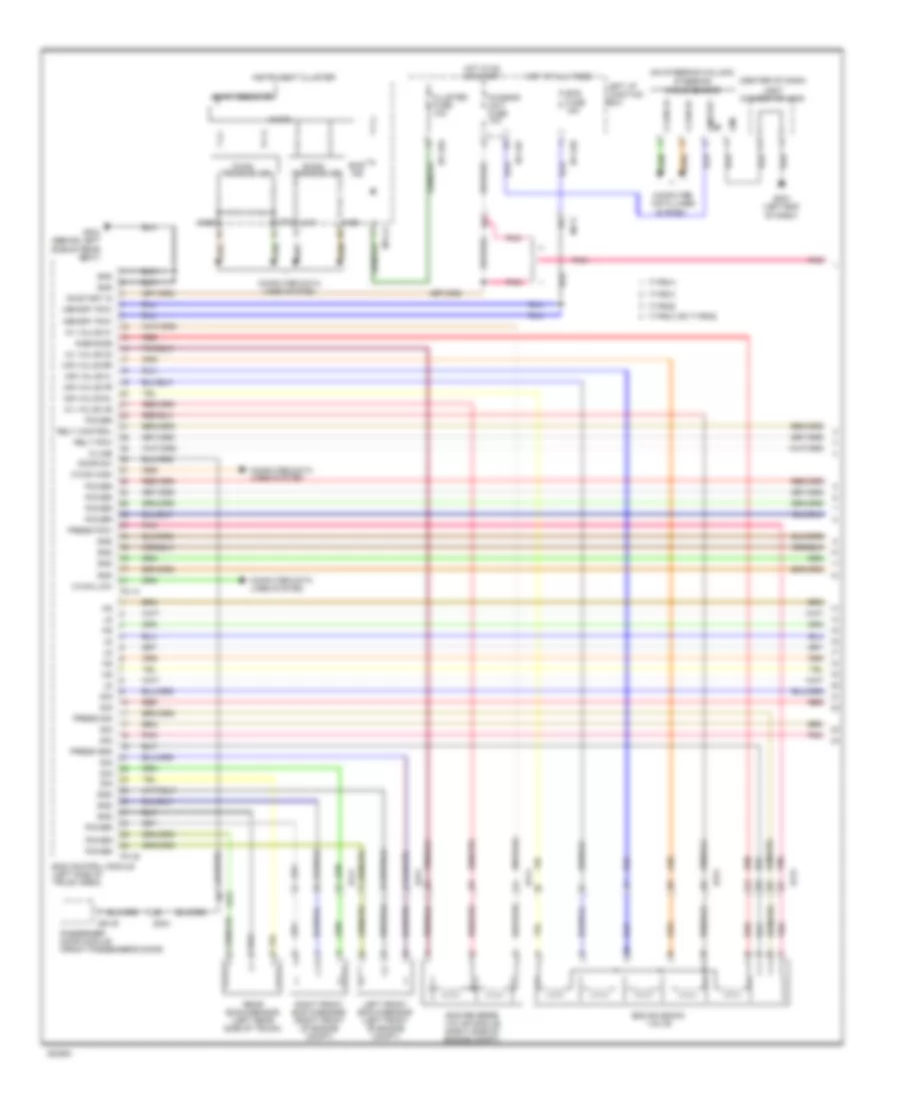
AIR CONDITIONING
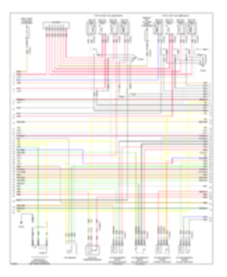
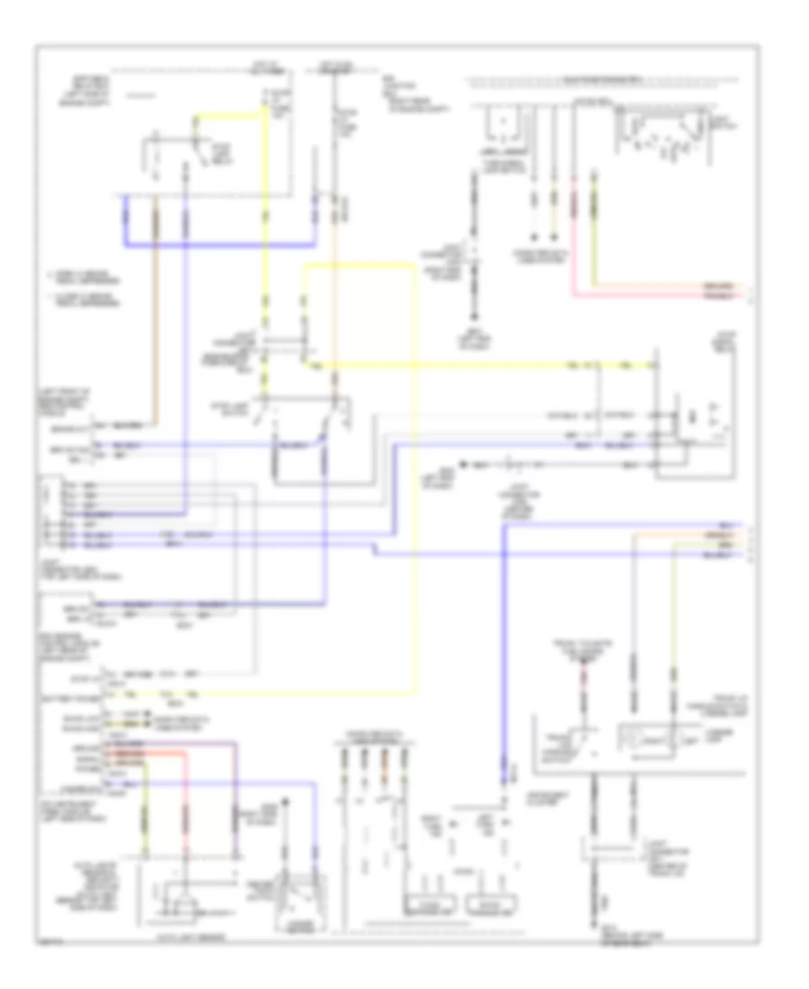
Automatic A/C Wiring Diagram (1 of 3) for Hyundai Equus Ultimate 2012
 https://portal-diagnostov.com/license.html
Automotive Electricians Portal FZCO
Automotive Electricians Portal FZCO
https://portal-diagnostov.com/license.html
https://portal-diagnostov.com/license.html
Automotive Electricians Portal FZCO
Automotive Electricians Portal FZCO
List of elements for Automatic A/C Wiring Diagram (1 of 3) for Hyundai Equus Ultimate 2012:
- (left end of dash) gm06
- (left front of engine compt) ge03
- (top left side of dash) j/c je02
- A/c control module (center of dash)
- A/con (b+) fuse 10a
- A/con (ig1) fuse 10a
- A/con fuse 10a
- Amb sensor (+)
- Ambient sensor (front of engine compt)
- Aqs fuse 10a
- Aqs sensor (front of engine compt)
- Aqs signal
- Auto ind
- B-can high
- B-can low
- Blower motor fuse 40a
- Blower relay
- Blower relay on input
- Body k-line
- Computer data lines system
- Console temperature actuator "a" (left center of dash)
- Console vent temperature actuator & switch (rear of center console)
- Cool console temp actr
- Cool console temp actr a
- Cool temp actuator
- Def led output (htd)
- Def mode actuator
- Defogger system
- Display sw
- Drv photo sensor (-)
- E/r junction box (right rear of engine compt)
- E/r-e1b
- E/r-e2b
- Ec01
- Ecv (+)
- Ecv (-)
- Ee21
- Ee31
- Electronic a/c compressor (left front of engine)
- Em21
- Em41
- Evap sensor (+)
- F/b
- F/b console temp actr a
- F/b console temp actuator
- F/b intake actuator
- F/b mode actuator
- F/b temp actuator
- Fet (d)
- Fet (g)
- Fre intake actuator
- Ge04 (lower right rear of engine compt)
- Gm02 (right side of dash)
- Ground
- Hot at all times
- Hot in on
- Hot in on or start
- I/p-lhc
- I/p-lhg
- Ill (+)
- Ill (-)
- Incar sensor (+)
- Interior lights system
- J/c jm21 (rear of center console)
- Left i/p junction block
- M-can high
- M-can low
- M07-a
- M07-b
- Memory power
- Mm11
- Motor (-)
- Nca
- Nca on input nca ill (-) nca ill (+)
- On/start input
- Pass photo sensor (-)
- Photo sensor (top right side of dash)
- Pnk
- Rec intake actuator
- Red
- Seats system
- Sensor ground
- Sensor pwr
- Vent mode actuator
- Vent switch
- Vent switch signal
- Vent temperature actuator
- Warm console temp actr
- Warm console temp actr a
- Warm temp actuator
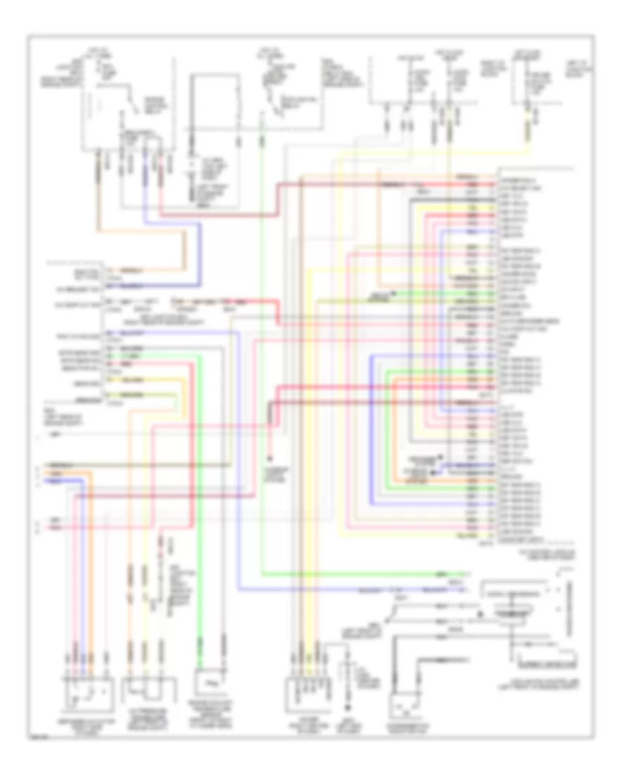
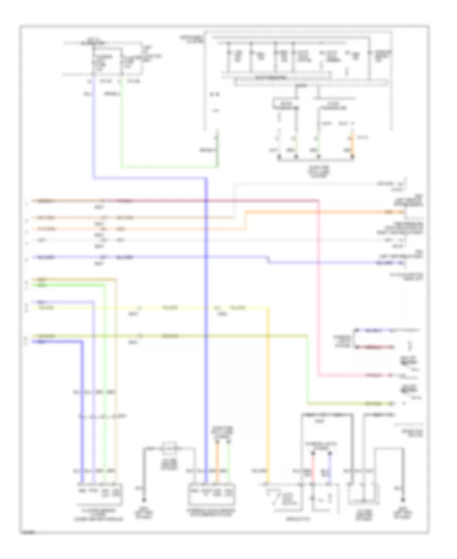
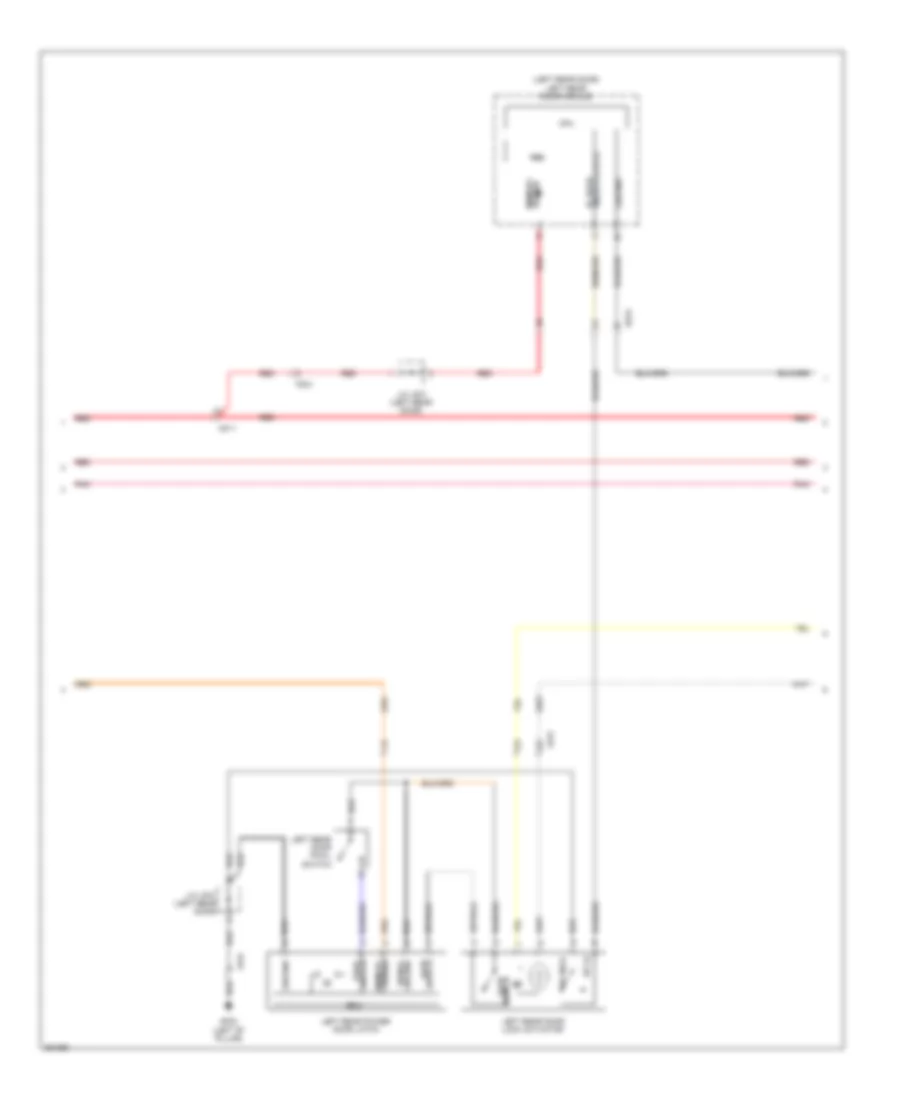
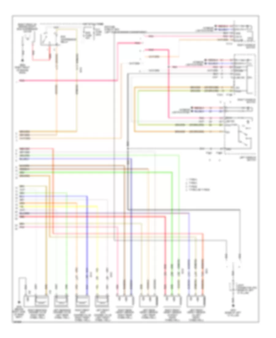
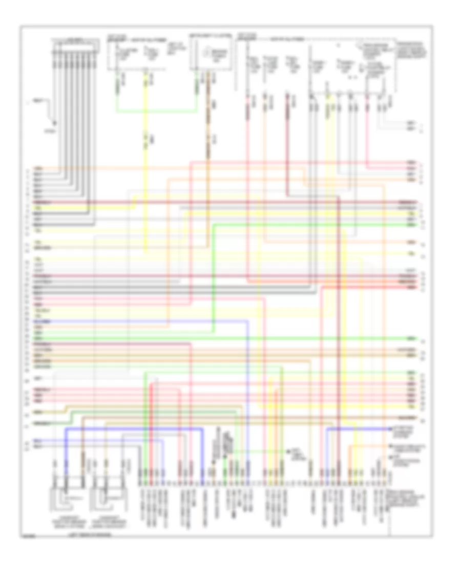
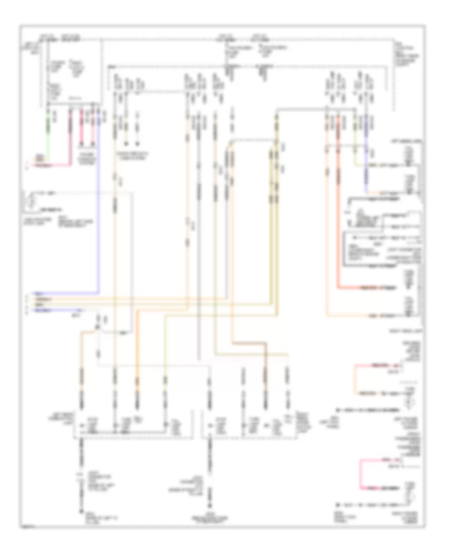
Automatic A/C Wiring Diagram (2 of 3) for Hyundai Equus Ultimate 2012
 https://portal-diagnostov.com/license.html
Automotive Electricians Portal FZCO
Automotive Electricians Portal FZCO
https://portal-diagnostov.com/license.html
https://portal-diagnostov.com/license.html
Automotive Electricians Portal FZCO
Automotive Electricians Portal FZCOList of elements for Automatic A/C Wiring Diagram (2 of 3) for Hyundai Equus Ultimate 2012:
- (left center of dash) console temperature actuator
- (right end of dash) j/c jm06
- (right side of dash) gm05
- (right side of dash) intake actuator
- (top center of windshield) auto defogger sensor
- (under left center of dash) mode actuator
- Active incar sensor (left center of dash)
- Blower motor (under right side of dash)
- Center facia switch
- Climate switch
- Display switch
- Driver temperature actuator
- Ee41
- Evaporator sensor (right side of dash, on hvac assembly)
- Fet (field effect transistor) (right side of dash)
- Fr21
- Gm02 (right side of dash)
- Humidity
- Mf21
- Passenger temperature actuator
- Pnk
- Red
- Sensor (+)
- Sensor (-)
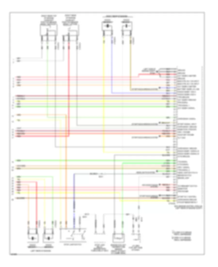
Automatic A/C Wiring Diagram (3 of 3) for Hyundai Equus Ultimate 2012
 https://portal-diagnostov.com/license.html
Automotive Electricians Portal FZCO
Automotive Electricians Portal FZCO
https://portal-diagnostov.com/license.html
https://portal-diagnostov.com/license.html
Automotive Electricians Portal FZCO
Automotive Electricians Portal FZCOList of elements for Automatic A/C Wiring Diagram (3 of 3) for Hyundai Equus Ultimate 2012:
- (left front
- A/c comp cut sig
- A/c control module (center of dash)
- A/c pressure transducer (left front of engine compt)
- A/c request sw
- A/c select sig
- A/con (acc) fuse 10a
- A/con (ig2) fuse 10a
- Acc/on input
- Auto defogger sens
- Climate sw
- Close
- Condenser fan radiator fan
- Cooling fan controller (left front of engine compt)
- Cooling fan fuse 60a
- Cooling fan relay
- Cruise switch fuse 10a
- Ctg-a
- Ctg-k
- Current detecting
- Def switch
- Defogger actuator (right side of dash)
- Defogger system
- Dia
- Dr temp enc a
- Dr temp enc b
- Dr temp enc c
- E/r fuse & relay box (left side of engine compt)
- E/r junction box (right rear of
- E/r junction box (right rear of engine compt)
- E/r-ca
- E/r-e2a
- E05-a
- E05-b
- Ec01
- Ecm (left rear of engine compt)
- Ects sens gnd
- Ects sens sig
- Ecu fuse 30a
- Em41
- Eng ctrl rly ctrl ctg-a
- Eng snsr 2 fuse 10a
- Engine control relay
- Engine coolant temperature sensor (front of right cylinder head)
- Engine e/r-e2a compt)
- F/b
- Ge01 (left front of engine compt)
- Ge03
- Gm01 (left end of dash)
- Ground
- Hot at all times
- Hot in acc or on
- Hot in on
- Hot in on or start
- I/p-lhc
- I/p-rhb
- I/p-rhd
- Ill (+)
- Ill (-)
- Interior lights system
- Ionizer (right center of dash)
- Ionizer dia
- Ionizer sig.a
- Ionizer sig.b
- J/c je02 (top left side of dash)
- J/c jm05 (center of dash)
- Key clk
- Key data
- Key sh/ld
- Led clk
- Led data
- Led dimming
- Led str
- Left i/p junction block
- M07-c
- M07-d
- Nca
- Of engine compt)
- On input
- On/start input
- Open
- Pnk
- Power conditioning
- Ps temp enc a
- Ps temp enc b
- Ps temp enc c
- Pwm to fan mod
- Pwn driver
- Red
- Right i/p junction block
- Rr c-line
- Seats system
- Sens gnd
- Sens pwr (5v)
- Sens sig
- Sig.a
- Sig.b
- Signal processing
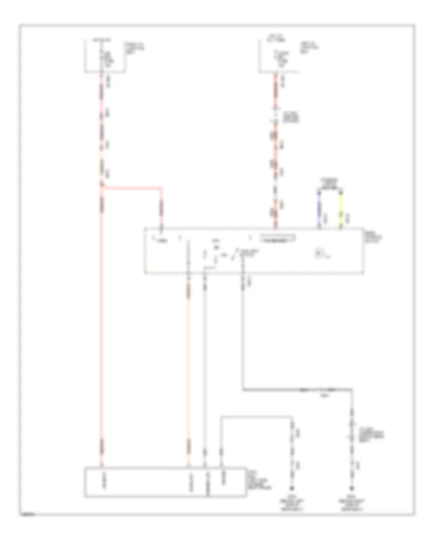
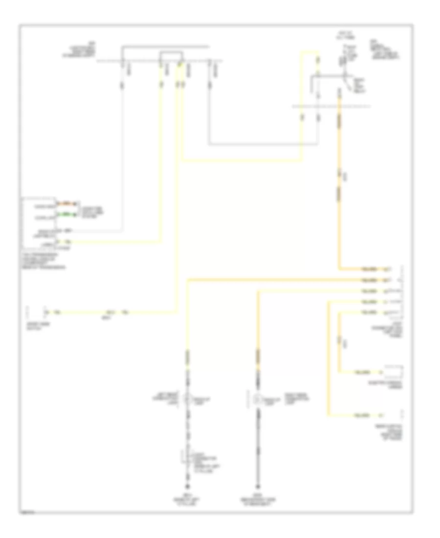
Cool Box Wiring Diagram for Hyundai Equus Ultimate 2012
 https://portal-diagnostov.com/license.html
Automotive Electricians Portal FZCO
Automotive Electricians Portal FZCO
https://portal-diagnostov.com/license.html
https://portal-diagnostov.com/license.html
Automotive Electricians Portal FZCO
Automotive Electricians Portal FZCOList of elements for Cool Box Wiring Diagram for Hyundai Equus Ultimate 2012:
- Audio (b+) fuse 15a
- Cool box
- Cool box (left side of rear seat frame)
- Cpu
- Fs31
- Fs41
- Gf04 (behind left side of rear seat)
- Gf08 (behind right side of rear seat)
- Ground
- Hi sig out
- Hot at all times
- Hot in on
- I/p-lhg
- I/p-rha
- Ice box fuse 15a
- Ill
- Ind
- Interior lights system
- J/c jm01 (center of dash)
- J/c js41 (under right side of rear seat)
- K-line logic
- Left i/p junction box
- Mf21
- On input
- Rear console switch
- Red/
- Right i/p junction box
- Running chk
- S37-a
- S37-b
- Ss41
- Ss51
- Switch
- Vireg
ANTI-LOCK BRAKES
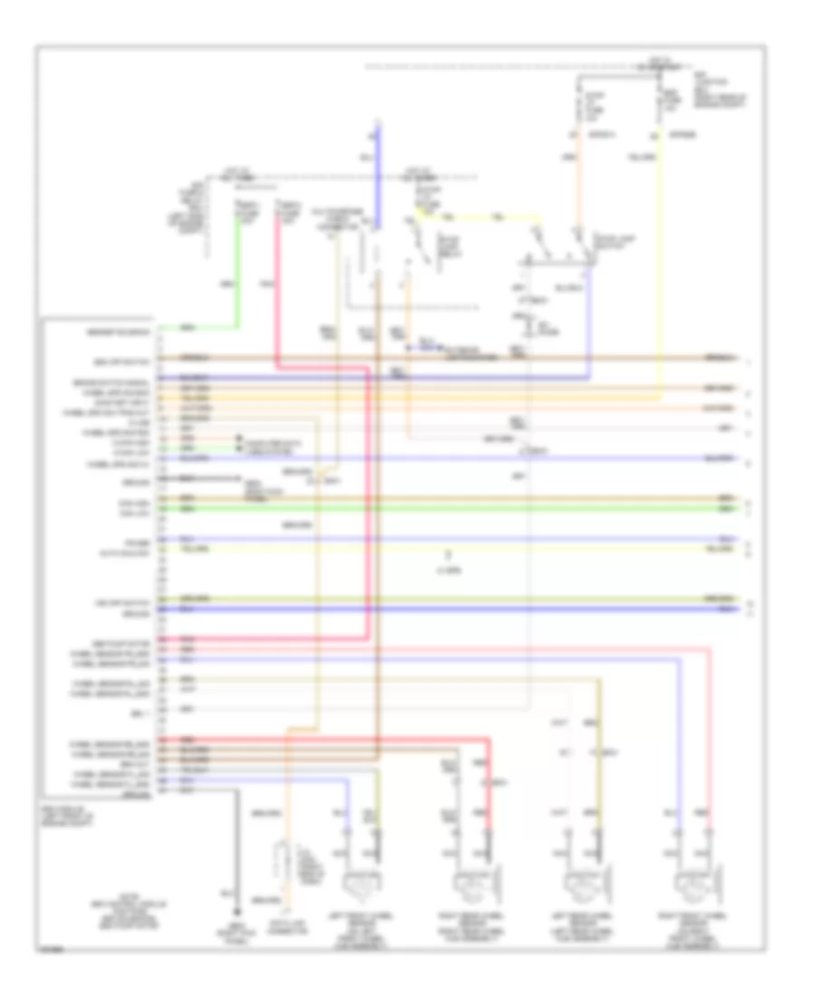
Anti-lock Brakes Wiring Diagram (1 of 2) for Hyundai Equus Ultimate 2012
 https://portal-diagnostov.com/license.html
Automotive Electricians Portal FZCO
Automotive Electricians Portal FZCO
https://portal-diagnostov.com/license.html
https://portal-diagnostov.com/license.html
Automotive Electricians Portal FZCO
Automotive Electricians Portal FZCOList of elements for Anti-lock Brakes Wiring Diagram (1 of 2) for Hyundai Equus Ultimate 2012:
- Abs pump motor
- Abs/esp solenoid
- Auto hold sw
- Brake switch signal
- Brk out
- Brl 1
- C-can high
- C-can low
- Can high
- Can low
- Computer data lines system
- Data link connector
- E/r fuse & relay box (left side of engine compt)
- E/r junction box (right rear of engine compt)
- E/r-e1a
- E/r-e2b
- Ef21
- Ef31
- Em31
- Esc module (left front of engine compt)
- Esc off switch
- Esp fuse 10a
- Esp-1 fuse 30a
- Esp-2 fuse 30a
- Exterior lights system
- Ge02 (right kick panel)
- Ground
- Hot at all times
- Hot in on or start
- J/c jm03 (right end of dash)
- K-line
- Left front wheel sensor (on left front wheel hub assembly)
- Left rear wheel sensor (left rear wheel hub assembly)
- Multipurpose check connector
- Nca
- Note: esc control module contains: esc solenoids, esc pump motor
- On/start input
- Pnk
- Power
- Red
- Right front wheel sensor (on right front wheel hub assembly)
- Right rear wheel sensor (right rear wheel hub assembly)
- Stop lamp relay
- Stop lamp switch
- Stop lp fuse 10a
- Vsm off switch
- W/ epb
- Wheel sensor fl_gnd
- Wheel sensor fl_sig
- Wheel sensor fr_gnd
- Wheel sensor fr_sig
- Wheel sensor rl_gnd
- Wheel sensor rl_sig
- Wheel sensor rr_gnd
- Wheel sensor rr_sig
- Wheel spd sig av
- Wheel spd sig ecm
- Wheel spd sig pdm
- Wheel spd sig tpms out
- Z01 diode
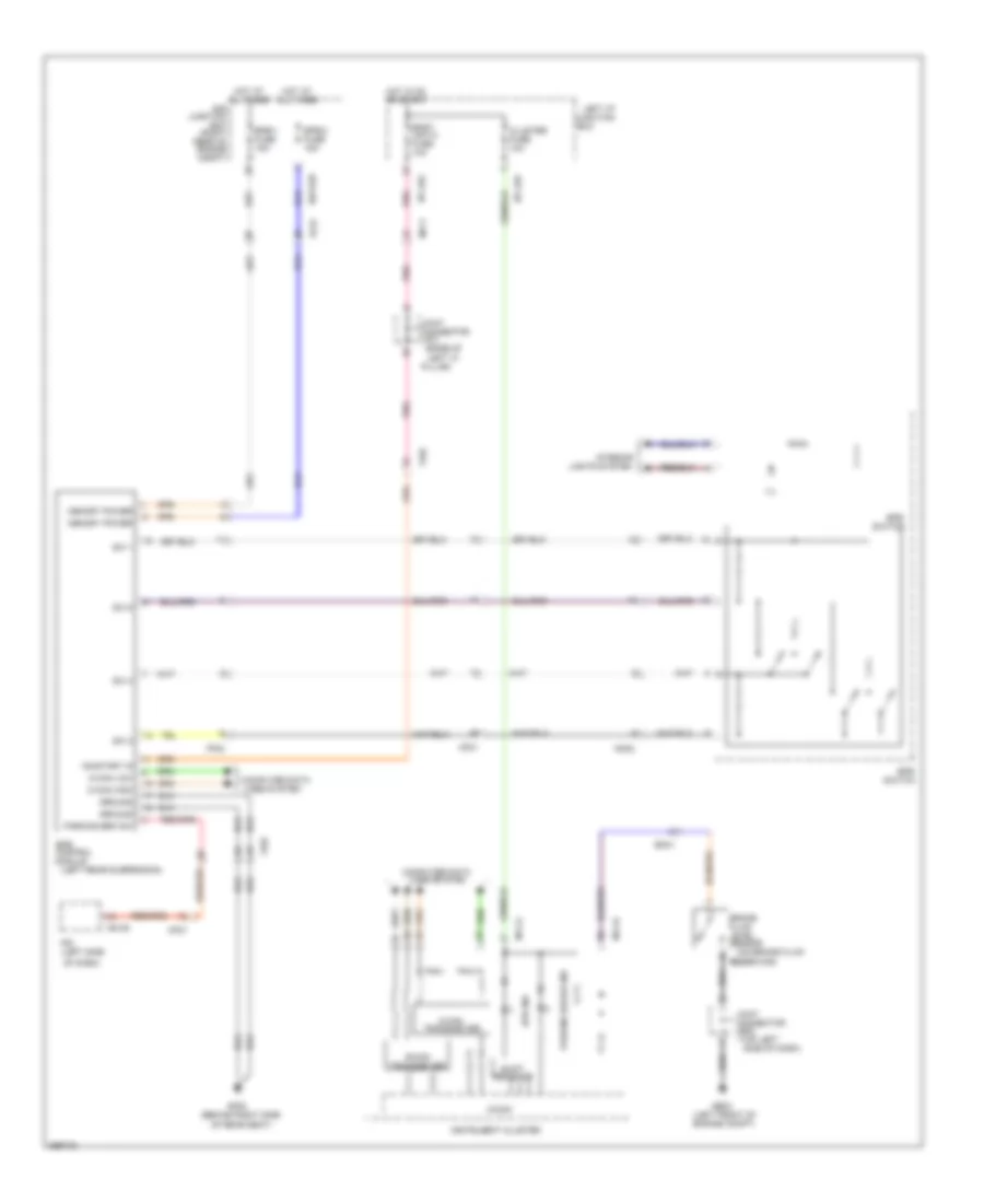
Anti-lock Brakes Wiring Diagram (2 of 2) for Hyundai Equus Ultimate 2012
 https://portal-diagnostov.com/license.html
Automotive Electricians Portal FZCO
Automotive Electricians Portal FZCO
https://portal-diagnostov.com/license.html
https://portal-diagnostov.com/license.html
Automotive Electricians Portal FZCO
Automotive Electricians Portal FZCOList of elements for Anti-lock Brakes Wiring Diagram (2 of 2) for Hyundai Equus Ultimate 2012:
- (left rear of engine compt)
- (under center console)
- (w/ epb)
- A/v & navigation head unit
- Abs ind
- Auto hold
- Auto hold (green)
- Auto hold (white)
- B-can transceiver
- C-can transceiver
- Can
- Can high
- Can low
- Chassis unit fuse 10a
- Cluster
- Cluster fuse 10a
- Cluster sensor
- Computer data lines system
- Crash pad switch
- Ctg-k
- Ec01
- Ecm
- Ef31
- Em21
- Em31
- Em41
- Epb switch
- Esc ind
- Esc off ind
- Esc off switch
- Gm01 (left end of dash)
- Gnd
- Hot in on or start
- I/p-lhe
- I/p-lhf
- Ill
- Instrument
- Interior lights system
- J/c jm05 (center of dash)
- Left i/p junction box
- Low
- M11-a
- M51-b
- Micom
- Mm02
- On/st
- Parking brake ind
- Pdm (left center of dash)
- Pwr
- Shift resistor
- Steering angle sensor (on steering column)
- Switch
- Tire pressure monitoring module (right center of dash)
- Vsm off ind
- Vsm off switch
Electric Parking Brake Wiring Diagram for Hyundai Equus Ultimate 2012
 https://portal-diagnostov.com/license.html
Automotive Electricians Portal FZCO
Automotive Electricians Portal FZCO
https://portal-diagnostov.com/license.html
https://portal-diagnostov.com/license.html
Automotive Electricians Portal FZCO
Automotive Electricians Portal FZCOList of elements for Electric Parking Brake Wiring Diagram for Hyundai Equus Ultimate 2012:
- (base of
- (behind right side
- (left front of engine compt)
- (left rear suspension)
- (left side
- (on brake fluid
- (top left
- B-can transceiver
- Body unit-2 fuse 10a
- Box
- Brake fluid level sensor
- C-can high
- C-can low
- C-can transceiver
- Cluster fuse 10a
- Computer data lines system
- Connector
- E/r junction box (right rear of engine compt)
- E/r-e2b
- Ef31
- Em31
- Epb
- Epb control module
- Epb ind
- Epb-1 fuse 15a
- Epb-2 fuse 15a
- Ff02
- Ge03
- Gf08
- Ground
- Hot at all times
- Hot in on or start
- I/p-lhe
- I/p-lhg
- Ill
- Instrument cluster
- Interior
- Ipm
- Je02
- Jf01
- Joint
- Left "c"
- Left i/p junction
- Lights system
- M11-a
- M11-b
- M40-b
- Memory power
- Mf11
- Mf21
- Micom
- Mm02
- Of dash)
- Of rear seat)
- On/start in
- Parking brake ind
- Parking brk sw
- Pillar)
- Pnk
- Reservoir)
- Shift resistor
- Side of dash)
- Sw 1
- Sw 2
- Sw 4
- Sw 5
- Switch
ANTI-THEFT
Forced Entry Wiring Diagram (1 of 4) for Hyundai Equus Ultimate 2012
 https://portal-diagnostov.com/license.html
Automotive Electricians Portal FZCO
Automotive Electricians Portal FZCO
https://portal-diagnostov.com/license.html
https://portal-diagnostov.com/license.html
Automotive Electricians Portal FZCO
Automotive Electricians Portal FZCOList of elements for Forced Entry Wiring Diagram (1 of 4) for Hyundai Equus Ultimate 2012:
- Ajar switch
- Body unit-1 fuse 10a
- Body unit-2 fuse 10a
- Computer data lines system
- Cpu
- D51-a
- D51-b
- D51-c
- Dd11
- Door lock
- Door lock relay
- Door lock/ips
- Door unlock
- Door unlock relay
- Dr lock (lh) fuse 10a
- Driver door lock actuator
- Driver door module (driver's door)
- Driver door pawl switch
- Driver power door latch
- Ecu
- Fd11
- Fet
- Fl door unlock state
- Gf01 (left kick panel)
- Gf04 (behind left side of rear seat)
- Ground
- Ground signal
- High
- Hot at all times
- Hot in on or start
- I/p-lhc
- I/p-lhf
- I/p-lhg
- J/c jd11 (driver's door)
- J/c jf01 (base of left "c" pillar)
- Key
- Key lock
- Key unlock
- Left i/p junction box
- Lock
- Low
- Memory power
- Mf11
- On/start input
- P/conn fuse 30a
- P/door (fl) fuse 15a
- P/door (rl) fuse 15a
- Pnk
- Power memory
- Red
- Reg
- Rr door mdl fuse 10a
- Switch ajar
- Switch pawl
- Transceiver b-can
- Unlock
Forced Entry Wiring Diagram (2 of 4) for Hyundai Equus Ultimate 2012
 https://portal-diagnostov.com/license.html
Automotive Electricians Portal FZCO
Automotive Electricians Portal FZCO
https://portal-diagnostov.com/license.html
https://portal-diagnostov.com/license.html
Automotive Electricians Portal FZCO
Automotive Electricians Portal FZCOList of elements for Forced Entry Wiring Diagram (2 of 4) for Hyundai Equus Ultimate 2012:
- (left rear door) left rear door module
- Cpu
- Dd31
- Dr lk
- Dr unlk
- Ecu
- Fd31
- Gf02 (left "b" pillar)
- Ground
- Ground signal
- J/c jd31 (left rear door)
- Left rear door lock actuator
- Left rear door pawl switch
- Left rear power door latch
- Mf11
- Pnk
- Power memory
- Red
- Reg
- Switch ajar
- Switch pawl
- Unlock state rl door
Forced Entry Wiring Diagram (3 of 4) for Hyundai Equus Ultimate 2012
 https://portal-diagnostov.com/license.html
Automotive Electricians Portal FZCO
Automotive Electricians Portal FZCO
https://portal-diagnostov.com/license.html
https://portal-diagnostov.com/license.html
Automotive Electricians Portal FZCO
Automotive Electricians Portal FZCOList of elements for Forced Entry Wiring Diagram (3 of 4) for Hyundai Equus Ultimate 2012:
- (right rear door) right rear door module
- Cpu
- Dd41
- Dr lk
- Dr unlk
- Ecu
- Fd21
- Fd31
- Fd41
- Gf04 (behind left side of rear seat)
- Gf09 (behind right side of rear seat)
- Ground
- Ground signal
- J/c jd41 (right rear door)
- J/c jf01 (base of left "c" pillar)
- Pnk
- Power memory
- Red
- Reg
- Right rear door lock actuator
- Right rear door pawl switch
- Right rear power door latch
- Switch ajar
- Switch pawl
- Unlock state rr door
Forced Entry Wiring Diagram (4 of 4) for Hyundai Equus Ultimate 2012
 https://portal-diagnostov.com/license.html
Automotive Electricians Portal FZCO
Automotive Electricians Portal FZCO
https://portal-diagnostov.com/license.html
https://portal-diagnostov.com/license.html
Automotive Electricians Portal FZCO
Automotive Electricians Portal FZCOList of elements for Forced Entry Wiring Diagram (4 of 4) for Hyundai Equus Ultimate 2012:
- (front passenger's door) j/c jd21
- Computer data lines system
- Cpu
- D61-a
- D61-c
- Dd21
- Door lock
- Door lock relay door unlock relay
- Dr lk
- Dr lock (rh) fuse 15a
- Dr unlk
- Driver ips motor door lock
- Driver power door latch
- Ecu
- Fd21
- Fr door unlock state
- Gf04 (behind left side of rear seat)
- Gf05 (right kick panel)
- Ground
- Ground signal
- High
- Hot at all times
- I/p-lhe
- I/p-rhe
- J/c jd21 (front passenger's door)
- J/c jf01 (base of left "c" pillar)
- Left i/p junction box
- Low
- Memory power
- Mf21
- On/start input
- P/door (fr) fuse 15a
- P/door (rr) fuse 15a
- Passenger door lock actuator
- Passenger door module (front passenger's door)
- Passenger door pawl switch
- Pnk
- Power distribution system
- Power memory
- Red
- Reg
- Relay
- Right i/p junction box
- Switch ajar
- Switch pawl
- Transceiver b-can
Immobilizer Wiring Diagram for Hyundai Equus Ultimate 2012
 https://portal-diagnostov.com/license.html
Automotive Electricians Portal FZCO
Automotive Electricians Portal FZCO
https://portal-diagnostov.com/license.html
https://portal-diagnostov.com/license.html
Automotive Electricians Portal FZCO
Automotive Electricians Portal FZCOList of elements for Immobilizer Wiring Diagram for Hyundai Equus Ultimate 2012:
- (right rear door) j/c jd41
- A/con (acc) fuse 10a
- A/con (b+) fuse 10a
- Acc/on in
- Auto light sensor & security indicator (auto light sensor: top left side of dash)
- Batt pwr
- Body unit fuse 10a
- Bum ant 1
- Bum ant 2
- Bumper antenna (center of rear bumper)
- Can-high
- Can-low
- Computer data lines system
- Dr lk/unlk
- E/r junction box (right rear of engine compt)
- E/r-e2b
- Em21
- Escl-2 fuse 10a
- Fd11
- Fd21
- Fd31
- Fd41
- Fr31
- Gf01 (left kick panel)
- Gf02 (left "b" pillar)
- Gf05 (right kick panel)
- Gf09 (behind right side of rear seat)
- Gm01 (left end of dash)
- Gm05 (right side of dash)
- Ground
- Hot at all times
- Hot in acc or on
- Hot in on
- Hot in on or start
- I/p-lha
- I/p-lhc
- I/p-lhd
- I/p-lhe
- I/p-rhd
- Interior antenna 1 (left center of dash)
- Interior antenna 2 (under center console)
- Intr ant 1
- Intr ant 2
- Ipm (instrument panel module) (left side of dash)
- Ipm fuse 10a
- J/c jd11 (driver's door)
- J/c jd21 (front passenger's door)
- J/c jd31 (left rear door)
- J/c jm05 (center of dash)
- Left button start antenna (behind center of rear seat)
- Left front smart outside handle
- Left i/p junction box
- Left rear smart outside handle
- M40-a
- M40-b
- M40-c
- M40-d
- Memory power
- Mf11
- Mf21
- Nca
- On input
- On/start in
- Power
- Power distribution system
- Push button
- Red
- Rf com
- Rf receiver (right center of dash)
- Right button start antenna (behind center of rear seat)
- Right front smart outside handle
- Right i/p junction box
- Right rear smart outside handle
- Security ind
- Security indicator
- Sensor sw
- Sensor switch
- Side ant 1
- Side ant 2
- Signal
- Start ant 1
- Start ant 2
- Trunk ant 1
- Trunk ant 2
- Trunk antenna (center front of trunk)
BODY CONTROL MODULES
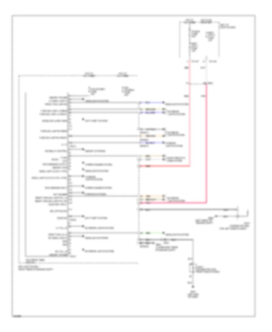
Front Area Module Wiring Diagram for Hyundai Equus Ultimate 2012
 https://portal-diagnostov.com/license.html
Automotive Electricians Portal FZCO
Automotive Electricians Portal FZCO
https://portal-diagnostov.com/license.html
https://portal-diagnostov.com/license.html
Automotive Electricians Portal FZCO
Automotive Electricians Portal FZCOList of elements for Front Area Module Wiring Diagram for Hyundai Equus Ultimate 2012:
- (left front of
- (lower right rear of engine compt)
- (top left side of dash)
- Anti-theft system
- B-can
- Body unit-1 fuse 10a
- Body unit-2 fuse 10a
- Burglar alarm horn
- Computer data lines system
- Connector je02
- Drl option sw
- E/r junction box (right rear of engine compt)
- E/r-e1a
- E/r-e1b
- E/r-e2a
- Em21
- Engine compt)
- Ext buzzer
- Exterior lights system
- Fam (front area module)
- Fam power-1 fuse 40a
- Fam power-2 fuse 40a
- Fam-a
- Fam-b
- Fam-c
- Front fog lamp rh
- Front fog lp lh
- Ge03
- Ge04
- Gm01 (left end of dash)
- Gnd
- Head lamp (lo) rly ctrl
- Headlights system
- High
- Hood sw
- Hot at all times
- Hot in on or start
- I/p-lhf
- I/p-lhg
- Ill (+)
- Ims relay control
- Interior lights system
- Joint
- Joint connector jm03 (right end of dash)
- Left i/p junction box
- Lh head lamp hi
- Lh tail lp
- Low
- Memory power
- Memory pwr
- Memory systems
- On/start input
- P/conn fuse 30a
- Pnk
- Rain sensor input
- Rain sensor output
- Rear turn sig lamp fail lh
- Rear turn sig lamp fail rh
- Red
- Rh head lamp hi
- Rh tail lp
- Room lamp auto cut rly ctrl
- Turn sig lamp lh front
- Turn sig lamp lh rear
- Turn sig lamp rh front
- Turn sig lamp rh rear
- Warning systems
- Wiper/washer system
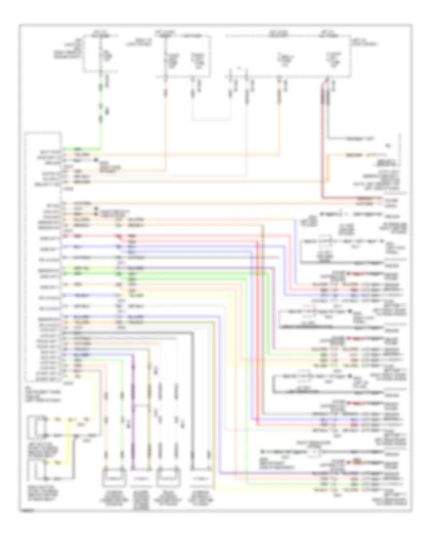
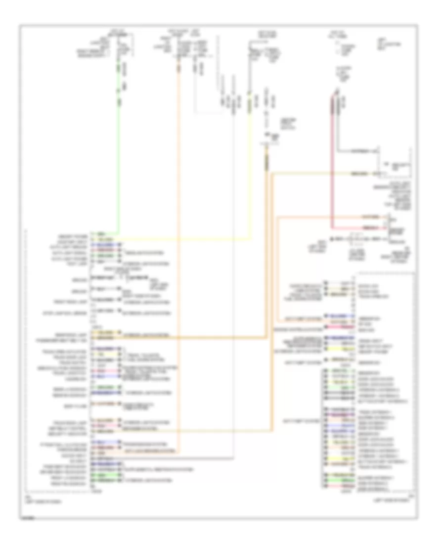
Instrument Panel Module Wiring Diagram for Hyundai Equus Ultimate 2012
 https://portal-diagnostov.com/license.html
Automotive Electricians Portal FZCO
Automotive Electricians Portal FZCO
https://portal-diagnostov.com/license.html
https://portal-diagnostov.com/license.html
Automotive Electricians Portal FZCO
Automotive Electricians Portal FZCOList of elements for Instrument Panel Module Wiring Diagram for Hyundai Equus Ultimate 2012:
- 'p' position l clutch sig
- (b+)
- (left end
- (left side of dash)
- (right center
- (right end of dash) j/c jm03
- (right rear of
- A/con
- A/con (acc) fuse 10a
- Acc/on input
- All times
- Anti-lock brakes system
- Anti-theft system
- Auto light ground
- Auto light power
- Auto light sensor & security
- Auto light signal
- B-can high
- B-can low
- Body k-line
- Body unit fuse 10a
- Body unit-2 fuse 10a
- Box
- Bumper antenna 1
- Bumper antenna 2
- Button start antenna 1
- Button start antenna 2
- Center facia switch
- Computer data
- Crash input
- Def relay control
- Def switch input
- Defogger system
- Door lock/unlock
- Doors system
- Driver seat buckle sw
- E/r
- E/r-e2b
- Em21
- Ems com
- Engine compt)
- Engine controls system
- Escl-2 fuse 10a
- Exterior lights system
- Foot lamp
- Front lh door sw
- Front rh door sw
- Front room lamp
- Fuse 10a
- Gm01
- Gm01 (left end of dash)
- Gm05 (right side of dash)
- Ground
- Hazard sw
- Headlights system
- Hot
- Hot at
- Hot in acc
- Hot in on
- I/p
- I/p-lha
- I/p-lhc
- I/p-lhd
- I/p-lhe
- I/p-lhg
- I/p-rhd
- In on
- Indicator (auto light sensor: top left side of dash)
- Interior 1 antenna 1
- Interior 1 antenna 2
- Interior 2 antenna 1
- Interior 2 antenna 2
- Interior lights system
- Ipm
- Ipm (left side of dash)
- Ipm fuse 10a
- J/c jm05 (center of dash)
- Junction
- Left i/p junction box
- Lines system
- M40-a
- M40-b
- M40-c
- M40-d
- Memory power
- Of dash)
- On input
- On/start input
- Or on
- Or start
- P/conn fuse 30a
- Parking brake
- Pass seat buckle sw
- Passenger seat belt ind
- Pnk
- Power distribution system
- Rear lh door sw
- Rear rh door sw
- Rear room lamp
- Receiver
- Red
- Rf com
- Right
- Sbr ind
- Security ind
- Security indicator
- Sensor sw
- Side antenna 1
- Side antenna 2
- Sig
- Ssb sw-2/l-push knob sw
- Stop lamp sw/l brake
- Transmissions system
- Trunk antenna 1
- Trunk antenna 2
- Trunk door lock
- Trunk lid switch
- Trunk open actuator
- Trunk open sw
- Trunk room lamp
- Trunk switch
- Trunk, tailgate, fuel
- Trunk, tailgate, fuel doors system
COMPUTER DATA LINES
Computer Data Lines Wiring Diagram (1 of 2) for Hyundai Equus Ultimate 2012
 https://portal-diagnostov.com/license.html
Automotive Electricians Portal FZCO
Automotive Electricians Portal FZCO
https://portal-diagnostov.com/license.html
https://portal-diagnostov.com/license.html
Automotive Electricians Portal FZCO
Automotive Electricians Portal FZCOList of elements for Computer Data Lines Wiring Diagram (1 of 2) for Hyundai Equus Ultimate 2012:
- (center of dash)
- (engine room
- (front passenger's door) passenger door module
- (left end of dash)
- (left side of engine compt)
- (or pnk)
- (right kick panel)
- 5:5
- 6:4
- A/v & navigation head unit
- Active headrest sensor module (under center console)
- Adaptive front lighting module (right center of dash)
- Auto head lamp leveling device sensor (left rear wheelwell)
- B-can hi
- B-can lo
- C-can hi
- C-can lo
- Camera module (right center of dash)
- D61-c
- Data link connector (below left side of dash)
- Driver active headrest (in driver's seat back)
- E/r fuse & relay box
- E/r junction box (right rear of engine compt)
- E/r-cb
- E/r-e1b
- E/r-e2b
- Ef31
- Em21
- Em31
- Em41
- Engine compt)
- Esc module (left front of
- Esp fuse 10a
- Esp-1 fuse 30a
- Esp-2 fuse 30a
- Fam
- Fam-b
- Fr21
- Fs11
- Fs31
- Fuse & relay box)
- Ge02
- Ge02 (right kick panel)
- Gf02 (left "c" pillar)
- Gm01
- Gm06 (left end
- Hot at all times
- Hot in on or start
- I/p-lha
- Instrument cluster
- J/c jf12 (base of right "c" pillar)
- J/c jm01 (center of dash)
- J/c jm02
- J/c jm03 (right end of dash)
- J/c jm12 (center of dash)
- J/c jr02 (right front of roof trim)
- K-line
- Ldws camera (front center of roof)
- Left i/p junction box
- M11-a
- M11-b
- M45-a
- M71-a
- Media module (right center of dash)
- Mf21
- Multipurpose check connector
- Of dash)
- Pnk
- Rear audio switch
- Rear console switch
- Rear curtain module (right side of trunk)
- Red
- Rr door mdl fuse 10a
- S27
- S37-a
- Spd sig
- Srs control module (under center console)
- Ss51
- Steering angle sensor (on steering column)
- Tire pressure monitoring module (right center of dash)
- Veh spd
Computer Data Lines Wiring Diagram (2 of 2) for Hyundai Equus Ultimate 2012
 https://portal-diagnostov.com/license.html
Automotive Electricians Portal FZCO
Automotive Electricians Portal FZCO
https://portal-diagnostov.com/license.html
https://portal-diagnostov.com/license.html
Automotive Electricians Portal FZCO
Automotive Electricians Portal FZCOList of elements for Computer Data Lines Wiring Diagram (2 of 2) for Hyundai Equus Ultimate 2012:
- (left rear of engine compt)
- (left rear of engine compt) ecm
- (left rear of trunk area) power trunk lid control module
- (lower right rear of transmission) tcm
- (remote control) multifunction switch
- (right rear
- (right side of dash) front & rear parking assist control module
- (right side of rear suspension)
- (right side of transmission) j/c jc13
- (top left side of dash) j/c jm11
- A/c control module (center of dash)
- B-can hi
- B-can lo
- C-can hi
- C-can hi ctg-zf
- C-can lo
- Clg-k
- Compt)
- Ctg-a
- D51-c
- Dd11
- Dd21
- Driver door module (driver's door)
- Driver ims control module
- E/r junction box
- E/r-cb
- E/r-e2b
- Ec01
- Ecs control module (left side
- Ee21
- Ee31
- Ef31
- Ehps module (right front of engine compt)
- Electronic control
- Em21
- Em31
- Epb control module (left rear suspension)
- F01-a
- F36-a
- Fd11
- Fd21
- Ff02
- Ff03
- Fr21
- Fs11
- Ipm (left side of dash)
- J/c je01 (engine room fuse & relay box)
- J/c je03 (right front of engine compt)
- J/c je11 (under right side of radiator)
- J/c jf04 (left side of trunk)
- J/c jf13 (right "b" pillar)
- J/c jf14 (base of right "c" pillar)
- J/c jf21 (left "b" pillar)
- J/c jf31
- J/c jm03 (right end of dash)
- K-line
- Left pre-safe seat belt
- M-can hi
- M-can lo
- M07-a
- M40-b
- M40-c
- M48
- M51-b
- M70-a
- Mf11
- Mf21
- Multi-function switch
- Of engine
- Of trunk area)
- Pdm (left center of dash)
- Pods module (under front passenger's seat)
- Red
- Right pre-safe seat belt
- S16-d
- Smart cruise control module (front of engine compt)
- Tilt & telescopic module (left side of dash)
- W/ epb
- W/o epb
- Wiper module
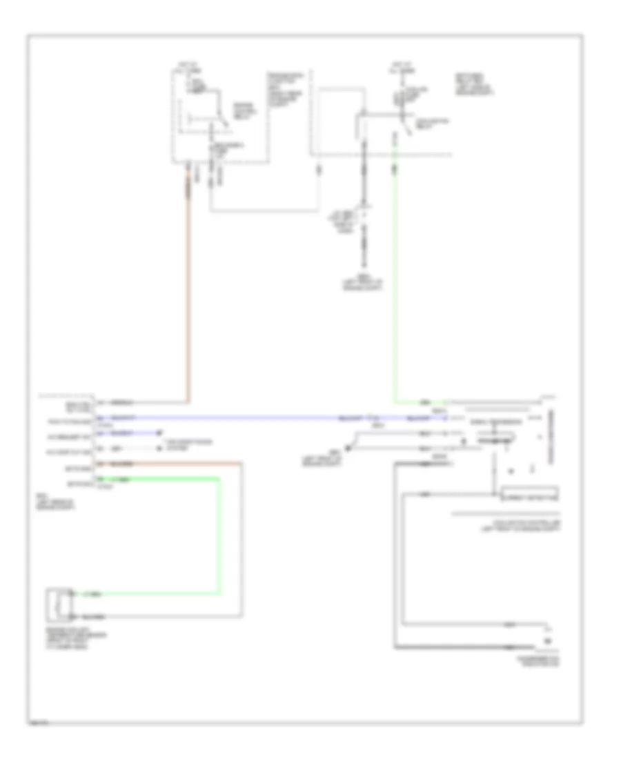
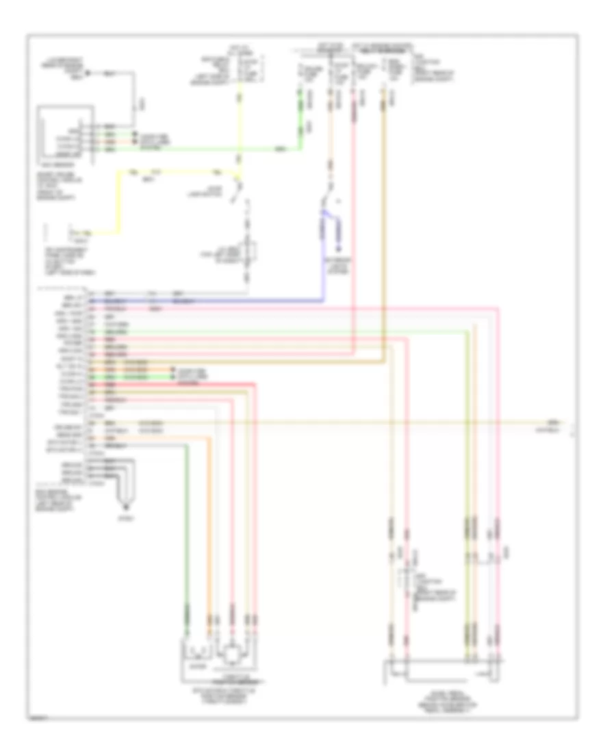
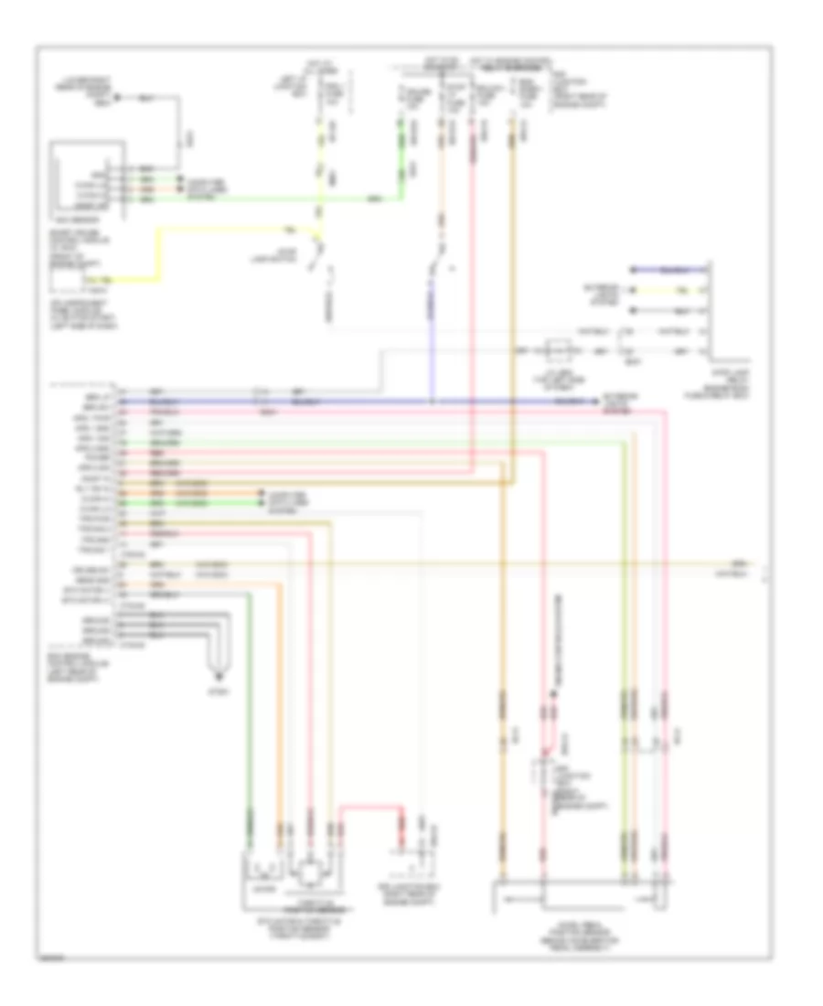
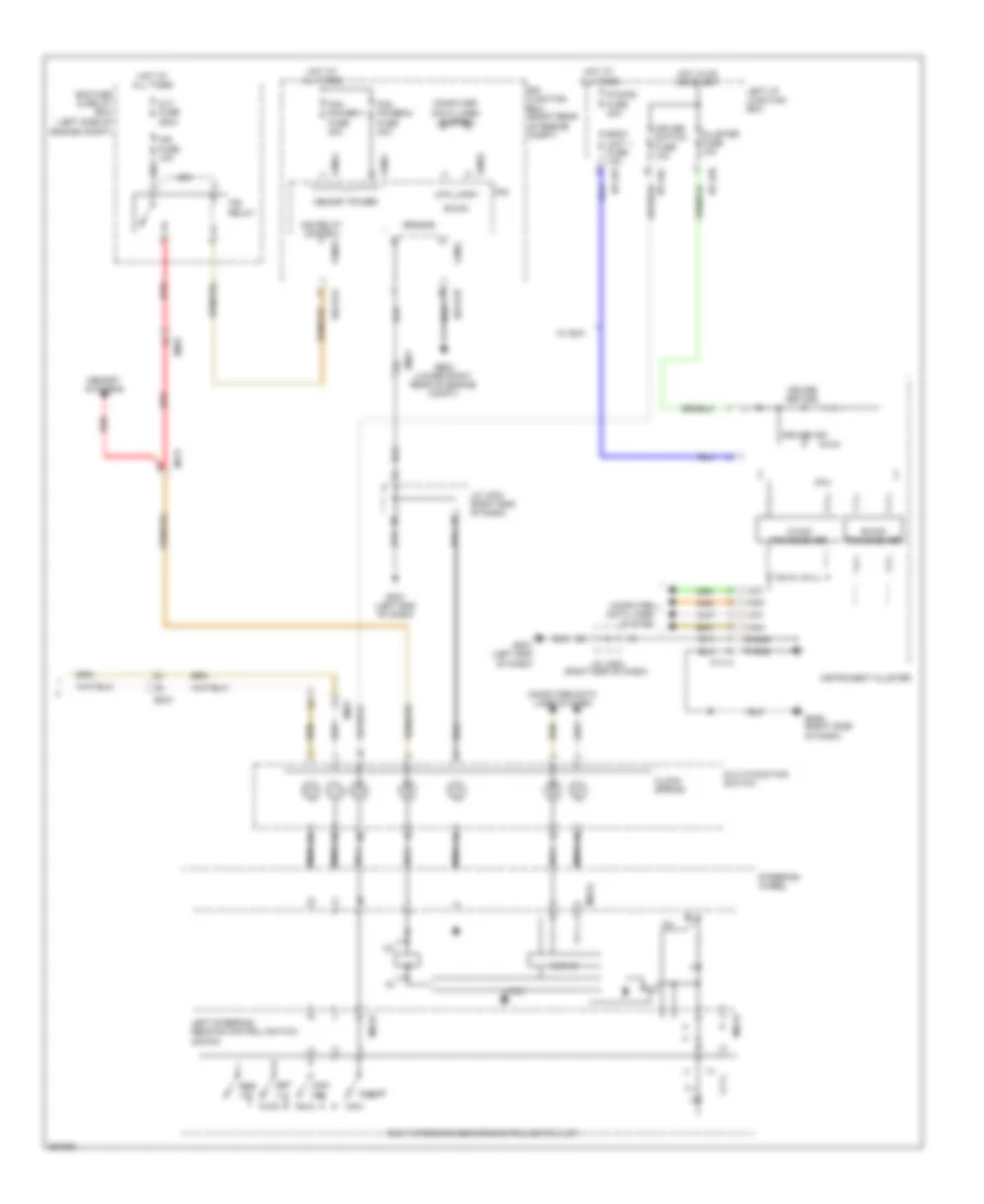
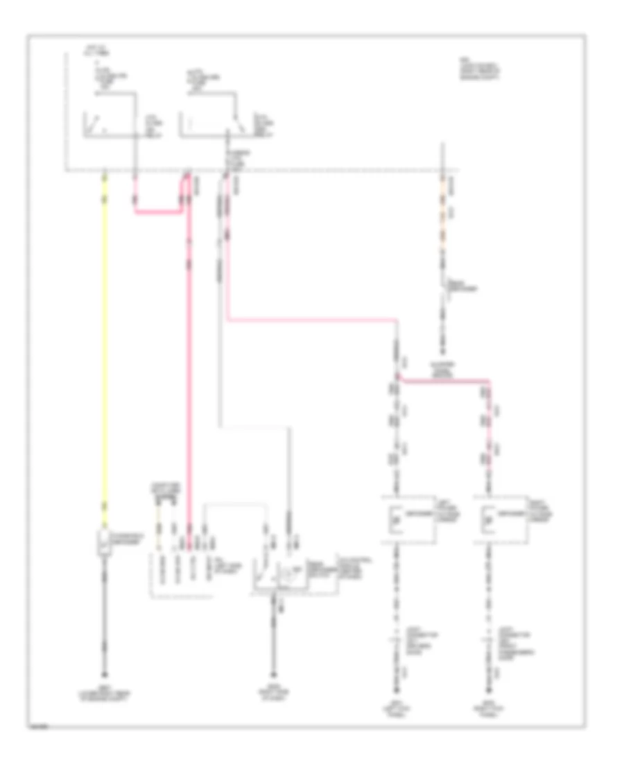
COOLING FAN
Cooling Fan Wiring Diagram for Hyundai Equus Ultimate 2012
 https://portal-diagnostov.com/license.html
Automotive Electricians Portal FZCO
Automotive Electricians Portal FZCO
https://portal-diagnostov.com/license.html
https://portal-diagnostov.com/license.html
Automotive Electricians Portal FZCO
Automotive Electricians Portal FZCOList of elements for Cooling Fan Wiring Diagram for Hyundai Equus Ultimate 2012:
- (left rear of engine compt)
- (right rear of engine compt)
- A/c comp cut sig
- A/c request sw
- Air conditioning system
- Condenser fan radiator fan
- Cooling fan controller (left front of engine compt)
- Cooling fan relay
- Cooling fuse 60a
- Ctg-a
- Ctg-k
- Current detecting
- Dash)
- E/r fuse & relay box (left side of engine compt)
- E/r-ca
- E/r-e2a
- E05-a
- E05-b
- Ec01
- Ecm
- Ects gnd
- Ects sig
- Ecu fuse 30a
- Eng ctrl rly ctrl
- Eng snsr 2 fuse 10a
- Engine control relay
- Engine coolant temperature sensor (front of right cylinder head)
- Engine room junction box
- Ge01 (left front of engine compt)
- Ge03 (left front of engine compt)
- Hot at all times
- J/c je02 (top left side of
- Nca
- Power conditioning
- Pwm to fan mod
- Pwn driver
- Signal processing
CRUISE CONTROL
4.6L
4.6L, Cruise Control Wiring Diagram (1 of 2) for Hyundai Equus Ultimate 2012
 https://portal-diagnostov.com/license.html
Automotive Electricians Portal FZCO
Automotive Electricians Portal FZCO
https://portal-diagnostov.com/license.html
https://portal-diagnostov.com/license.html
Automotive Electricians Portal FZCO
Automotive Electricians Portal FZCOList of elements for 4.6L, Cruise Control Wiring Diagram (1 of 2) for Hyundai Equus Ultimate 2012:
- (front of engine compt)
- (lower right rear of engine compt) ge04
- (w/o scc)
- Accel pedal position sensor (behind accelerator pedal assembly)
- Aps 1 gnd
- Aps 1 pwr
- Aps 1 sig
- Aps 2 gnd
- Aps 2 sig
- Brk lp
- Brk sw
- C-can hi
- C-can lo
- Computer data lines system
- Cruise fuse 10a
- Cruise sw
- Ctg-a
- Ctg-k
- E/r fuse & relay box (left side of engine compt)
- E/r junction box (right rear of e/r-e2a engine compt)
- E/r junction box (right rear of engine compt)
- E/r-ca
- E/r-cb
- E/r-e1a
- E/r-e2a
- Ec01
- Ecm (engine control module) (left rear of engine compt)
- Ecu(ig1) fuse 10a
- Ee21
- Em31
- Eng snsr-1 fuse 10a
- Etc motor & throttle position sensor (throttle body)
- Etc motor (+)
- Etc motor (-)
- Exterior lights system
- Gnd
- Ground
- Gtg01
- Hot at all times
- Hot in on or start
- Hot w/ engine control relay energized
- Ipm (instrument panel module) (w/ button start) (left side of dash)
- J/c je02 (top left side of dash)
- M40-c
- Motor
- On/st i/p
- On/st in
- Power
- Red
- Rly 'on' in
- Scc sensor
- Sens gnd
- Smart cruise control module (w/ scc)
- Stop lamp switch
- Stop lp fuse 10a
- Throttle position sensor
- Tps gnd
- Tps pwr
- Tps sig 1
- Tps sig 2
4.6L, Cruise Control Wiring Diagram (2 of 2) for Hyundai Equus Ultimate 2012
 https://portal-diagnostov.com/license.html
Automotive Electricians Portal FZCO
Automotive Electricians Portal FZCO
https://portal-diagnostov.com/license.html
https://portal-diagnostov.com/license.html
Automotive Electricians Portal FZCO
Automotive Electricians Portal FZCOList of elements for 4.6L, Cruise Control Wiring Diagram (2 of 2) for Hyundai Equus Ultimate 2012:
- (+)
- (-)
- 12v
- Alt fuse 200a
- B-can
- B-can transceiver
- Body unit 1 fuse 10a
- C-can transceiver
- Can ic
- Can- cel
- Clock spring
- Cluster fuse 10a
- Computer data lines system
- Cruise ind
- Cruise set ind
- Cruise switch fuse 10a
- E/r fuse & relay box (left side of engine compt)
- E/r junction box (right rear of engine compt)
- E/r-e1a
- E/r-e1b
- Ec01
- Em21
- Em31
- Fam
- Fam power-1 fuse 40a
- Fam power-2 fuse 40a
- Fam-a
- Fam-b
- Fam-c
- Ge04 (lower right rear of engine compt)
- Gm01 (left end
- Gm01 (left end of dash)
- Gm05 (right side of dash)
- Ground
- High
- Hot at all times
- Hot in on or start
- I/p-lhc
- I/p-lhe
- I/p-lhf
- Ill
- Ims fuse 10a
- Ims relay
- Ims relay control
- Instrument cluster
- J/c jm03 (right end of dash)
- Left i/p junction box
- Left steering remote control switch (down)
- Low
- M11-a
- M92-a
- M92-b
- Mcu
- Memory power
- Memory systems
- Mf21
- Multi-function switch
- Nca
- Of dash)
- On/off
- P gnd
- P/conn fuse 30a
- Red
- Res (+)
- Right steering remote control switch (up)
- S gnd
- Set (-)
- Steering wheel
- W/ scc
5.0L
5.0L, Cruise Control Wiring Diagram (1 of 2) for Hyundai Equus Ultimate 2012
 https://portal-diagnostov.com/license.html
Automotive Electricians Portal FZCO
Automotive Electricians Portal FZCO
https://portal-diagnostov.com/license.html
https://portal-diagnostov.com/license.html
Automotive Electricians Portal FZCO
Automotive Electricians Portal FZCOList of elements for 5.0L, Cruise Control Wiring Diagram (1 of 2) for Hyundai Equus Ultimate 2012:
- (front of engine compt)
- (lower right rear of engine compt) ge04
- (w/o scc)
- Accel pedal position sensor (behind accelerator pedal assembly)
- Aps 1 gnd
- Aps 1 pwr
- Aps 1 sig
- Aps 2 gnd
- Aps 2 sig
- Brk lp
- Brk sw
- C-can hi
- C-can lo
- Computer data lines system
- Cruise fuse 10a
- Cruise sw
- Ctg-ag
- Ctg-kg
- E/r junction box (right e/r-e2a rear of engine compt)
- E/r junction box (right rear of engine compt)
- E/r-ca
- E/r-cb
- E/r-e1a
- E/r-e2a
- Ec41
- Ecm (engine control module) (left rear of engine compt)
- Ecu(ig1) fuse 10a
- Ee21
- Em31
- Em41
- Eng snsr-1 fuse 10a
- Engine controls system
- Etc motor & throttle position sensor (throttle body)
- Etc motor (+)
- Etc motor (-)
- Exterior lights system
- Gnd
- Ground
- Gtg01
- Hot at all times
- Hot in on or start
- Hot w/ engine control relay energized
- I/p-lhf
- Ipm (instrument panel module) (w/ button start) (left side of dash)
- J/c je02 (top left side of dash)
- Left i/p junction box
- M40-c
- Motor
- On/st i/p
- On/st in
- Pdm 1 fuse 10a
- Power
- Red
- Rly 'on' in
- Scc sensor
- Sens gnd
- Smart cruise control module (w/ scc)
- Stop lamp relay (engine room fuse & relay box)
- Stop lamp switch
- Stop lp fuse 10a
- Throttle position sensor
- Tps gnd
- Tps pwr
- Tps sig 1
- Tps sig 2
5.0L, Cruise Control Wiring Diagram (2 of 2) for Hyundai Equus Ultimate 2012
 https://portal-diagnostov.com/license.html
Automotive Electricians Portal FZCO
Automotive Electricians Portal FZCO
https://portal-diagnostov.com/license.html
https://portal-diagnostov.com/license.html
Automotive Electricians Portal FZCO
Automotive Electricians Portal FZCOList of elements for 5.0L, Cruise Control Wiring Diagram (2 of 2) for Hyundai Equus Ultimate 2012:
- (+)
- (-)
- 12v
- Alt fuse 200a
- B-can
- B-can transceiver
- Body unit 1 fuse 10a
- C-can transceiver
- Can ic
- Can- cel
- Clock spring
- Cluster fuse 10a
- Computer data lines system
- Cruise ind
- Cruise set ind
- Cruise switch fuse 10a
- E/r fuse & relay box (left side of engine compt)
- E/r junction box (right rear of engine compt)
- E/r-e1a
- E/r-e1b
- Ec01
- Em21
- Em31
- Fam
- Fam power-1 fuse 40a
- Fam power-2 fuse 40a
- Fam-a
- Fam-b
- Fam-c
- Ge04 (lower right rear of engine compt)
- Gm01 (left end
- Gm01 (left end of dash)
- Gm05 (right side of dash)
- Ground
- High
- Hot at all times
- Hot in on or start
- I/p-lhc
- I/p-lhe
- I/p-lhf
- Ill
- Ims fuse 10a
- Ims relay
- Ims relay control
- Instrument cluster
- J/c jm03 (right end of dash)
- Left i/p junction box
- Left steering remote control switch (down)
- Low
- M11-a
- M92-a
- M92-b
- Mcu
- Memory power
- Memory systems
- Mf21
- Multi-function switch
- Nca
- Of dash)
- On/off
- P gnd
- P/conn fuse 30a
- Red
- Res (+)
- Right steering remote control switch (up)
- S gnd
- Set (-)
- Steering wheel
- W/ scc
DEFOGGERS
Defoggers Wiring Diagram for Hyundai Equus Ultimate 2012
 https://portal-diagnostov.com/license.html
Automotive Electricians Portal FZCO
Automotive Electricians Portal FZCO
https://portal-diagnostov.com/license.html
https://portal-diagnostov.com/license.html
Automotive Electricians Portal FZCO
Automotive Electricians Portal FZCOList of elements for Defoggers Wiring Diagram for Hyundai Equus Ultimate 2012:
- (fr) relay
- (rr) relay
- A/c control module (center of dash)
- B-can high
- B-can low
- Computer data lines system
- Dd11
- Dd21
- Defogger
- E/r junction box (right rear of engine compt)
- E/r-e1b
- E/r-e2a
- E/r-e2b
- Ef21
- Em21
- Fd11
- Fd21
- Ge07 (lower right rear of engine compt)
- Gf01 (left kick panel)
- Gf05 (right kick panel)
- Gm02 (right side of dash)
- Hot at all times
- Htd glass
- Htd glass (fr) fuse 15a
- Htd glass (rr) fuse 40a
- Ind
- Ipm (left side of dash)
- Joint connector jd11 (driver's door)
- Joint connector jd21 (front passenger's door)
- Left power outside mirror
- M07-a
- M07-d
- M40-b
- M40-c
- Mirror htd fuse 10a
- Nca
- Pnk
- Quarter panel ground
- Rear defogger
- Rear defogger switch
- Right power outside mirror
- Rly ctrl
- Sw input
- Windshield defogger
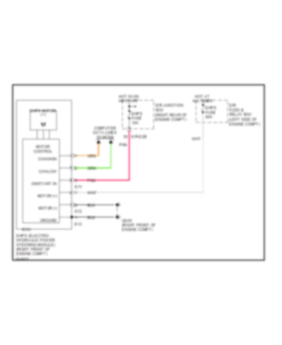
ELECTRONIC POWER STEERING
Electronic Power Steering Wiring Diagram for Hyundai Equus Ultimate 2012
 https://portal-diagnostov.com/license.html
Automotive Electricians Portal FZCO
Automotive Electricians Portal FZCO
https://portal-diagnostov.com/license.html
https://portal-diagnostov.com/license.html
Automotive Electricians Portal FZCO
Automotive Electricians Portal FZCOList of elements for Electronic Power Steering Wiring Diagram for Hyundai Equus Ultimate 2012:
- (right rear of engine compt)
- Can-high
- Can-low
- Computer data lines system
- E/r fuse & relay box (left side of engine compt)
- E/r junction box
- E/r-e2b
- E11
- E12
- E13
- Ecu
- Ehps (electro- hydraulic power steering module) (right front of engine compt)
- Ehps fuse 10a
- Ehps fuse 80a
- Ehps motor
- Ge05 (right front of engine compt)
- Ground
- Hot at all times
- Hot in on or start
- Motor (+)
- Motor (-)
- Motor control
- On/start in
- Pnk
ELECTRONIC SUSPENSION
Electronic Suspension Wiring Diagram (1 of 2) for Hyundai Equus Ultimate 2012
 https://portal-diagnostov.com/license.html
Automotive Electricians Portal FZCO
Automotive Electricians Portal FZCO
https://portal-diagnostov.com/license.html
https://portal-diagnostov.com/license.html
Automotive Electricians Portal FZCO
Automotive Electricians Portal FZCOList of elements for Electronic Suspension Wiring Diagram (1 of 2) for Hyundai Equus Ultimate 2012:
- (center of dash)
- (on steering column)
- Air valve fl
- Air valve fr
- Air valve rl
- Air valve rr
- Ambiance
- Av valve hs
- Av valve m1
- Av valve m2
- B-can
- C-can
- C-can hi
- C-can high
- C-can lo
- C-can low
- Chassis unit fuse 10a
- Cluster fuse 10a
- Computer data
- Computer data lines
- Computer data lines system
- D61-b
- Dd21
- Door sw
- Ecs control module (left side of trunk area)
- Ecs fuse 15a
- Ecs ind
- Ecs reverse valve module (right side of engine compt)
- Ecs solenoid valve
- Ef31
- Ef41
- Ef51
- F01-a
- F01-b
- Fd21
- Gf04 (behind left side of rear seat)
- Gm01 (left end of dash)
- Gnd
- High
- Hot at all times
- Hot in on or start
- I/p-lhd
- I/p-lhe
- I/p-lhf
- Instrument cluster
- Joint connector jm05
- K-line
- Left front ecs g-sensor (left front of engine compt)
- Left i/p junction box
- Lines system
- Low
- M11-a
- Memory pow
- Mf11
- Micom
- On/start in
- On/strt in
- Passenger door module (front passenger's door)
- Pnk
- Power
- Press gnd
- Press pow
- Press sig
- Rear ecs g-sensor (left rear side of trunk)
- Red
- Rely control
- Rely pow
- Right front ecs g-sensor (right front of engine compt)
- Shift resistor
- Sig
- Steering angle sensor
- System
- Transceiver
- Type-a
- Type-c
- Type-c or type-e
- Type-e
Electronic Suspension Wiring Diagram (2 of 2) for Hyundai Equus Ultimate 2012
 https://portal-diagnostov.com/license.html
Automotive Electricians Portal FZCO
Automotive Electricians Portal FZCO
https://portal-diagnostov.com/license.html
https://portal-diagnostov.com/license.html
Automotive Electricians Portal FZCO
Automotive Electricians Portal FZCOList of elements for Electronic Suspension Wiring Diagram (2 of 2) for Hyundai Equus Ultimate 2012:
- "c" pillar)
- (+)
- (-)
- (right front of engine compt) ecs compressor motor
- Alt fuse 200a
- Cpu
- E/r fuse & relay box (left side of engine compartment)
- Ecs compressor relay
- Ecs fuse 40a
- Ef31
- Ef41
- Ef51
- F15-c
- F15-e
- F17-a
- F17-c
- F17-e
- F19
- F97
- Ge08 (right front of engine room)
- Gf03 (base of left "c" pillar)
- Gf08 (behind right side of rear seat)
- Gnd
- Hot at all times
- Ill
- Interior lights system
- Joint connector jf02 (base of left
- K-line
- Led ind
- Left console switch
- Left front ecs damper valve (left front wheel well)
- Left front height sensor (in left front wheelwell)
- Left rear ecs damper valve (left rear wheel well)
- Left rear height sensor (left rear wheelwell)
- Low
- On in
- Pnk
- Pow
- Power
- Red
- Right console switch
- Right front ecs damper valve (right front wheel well)
- Right front height sensor (in right front wheelwell)
- Right rear ecs damper valve (right rear wheel well)
- Right rear height sensor (right rear wheelwell)
- Sig
- Type-a
- Type-c
- Type-c or type-e
- Type-e
ENGINE PERFORMANCE
4.6L
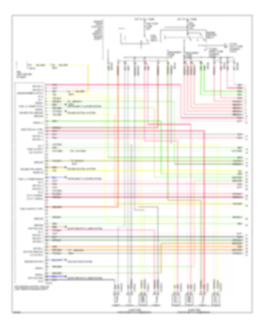
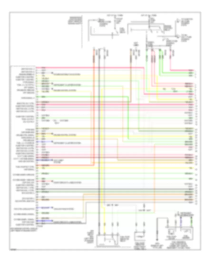
4.6L, Engine Performance Wiring Diagram (1 of 5) for Hyundai Equus Ultimate 2012
 https://portal-diagnostov.com/license.html
Automotive Electricians Portal FZCO
Automotive Electricians Portal FZCO
https://portal-diagnostov.com/license.html
https://portal-diagnostov.com/license.html
Automotive Electricians Portal FZCO
Automotive Electricians Portal FZCOList of elements for 4.6L, Engine Performance Wiring Diagram (1 of 5) for Hyundai Equus Ultimate 2012:
- Ccp can high
- Ccp can low
- Ccv output
- Computer data lines system
- Cooling fans system
- Cruise control system
- Cruise ctrl ground
- Cruise ctrl signal
- Ctg-a
- Ctg24-1
- Ctg24-2
- Ctg24-3
- Ctg24-4
- Ctg24-5
- Ctg24-6
- Ctg24-7
- Ctg24-8
- Cvvt 1 signal
- Cvvt 2 signal
- E/r-ca
- E/r-cb
- E/r-e1a
- E/r-e2a
- Ec01
- Ecm (engine control module) (left rear of engine compt)
- Ecu fuse 30a
- Em31
- Eng ctrl rly ctrl
- Eng snsr-2 fuse 10a
- Eng snsr-3 fuse 15a
- Engine control relay
- Engine fan pwm
- Engine room junction box (right rear of engine compt)
- Engine speed output
- Fuel lvl snsr middle
- Fuel lvl snsr total
- Fuel pump fuse 20a
- Fuel pump relay
- Fuel pump rly ctrl
- Ground
- Hot at all times
- Ign coil 1
- Ign coil 2
- Ign coil 3
- Ign coil 4
- Ign coil 5
- Ign coil 6
- Ign coil 7
- Ign coil 8
- Ind ctrl eng chk
- Inj 1
- Inj 2
- Inj 3
- Inj 4
- Inj 5
- Inj 6
- Inj 7
- Inj 8
- Injectors (top of left cylinder bank)
- Injectors (top of right cylinder bank)
- Instrument cluster system
- M51-b
- Motor (+)
- Motor (-)
- Pcsv output
- Pdm (left center of dash)
- Pnk
- Red
- Signal
- Signal a
- Signal b
- To eng snsr-1 fuse (diagram 4 of 5)
- To ign coil-1 fuse (diagram 3 of 5)
- Viv output
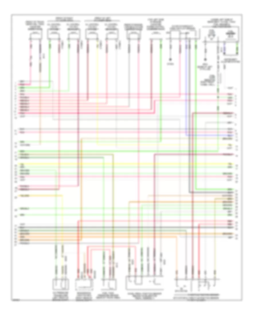
4.6L, Engine Performance Wiring Diagram (2 of 5) for Hyundai Equus Ultimate 2012
 https://portal-diagnostov.com/license.html
Automotive Electricians Portal FZCO
Automotive Electricians Portal FZCO
https://portal-diagnostov.com/license.html
https://portal-diagnostov.com/license.html
Automotive Electricians Portal FZCO
Automotive Electricians Portal FZCOList of elements for 4.6L, Engine Performance Wiring Diagram (2 of 5) for Hyundai Equus Ultimate 2012:
- (front of left cylinder head)
- (front of right cylinder head)
- (front of trunk, near fuel tank) canister close valve
- (in air intake duct) mass air flow sensor
- (rear of engine) variable intake manifold valve
- (right front
- (top left side of engine) canister purge control solenoid valve
- (under left side of rear seat, in fuel tank)
- A/c pressure transducer (left front of engine compt)
- Accel pedal position sensor (behind accelerator pedal assembly)
- Afm
- Afs
- Ctg05-1
- Ctg05-2
- Ctg05-3
- Ctg05-4
- E/r-ca
- E/r-e2a
- Ec01
- Ef11
- Engine room junction box (right rear of engine compt)
- Etc motor
- Etc motor & throttle position sensor (throttle body)
- Fuel pump motor
- Fuel pump resistor
- Fuel sender
- Fuel sender & fuel pump motor
- Fuel tank pressure sensor (rear of trunk area)
- Gf03 (base of left "c" pillar)
- Gtg04
- Instrument cluster system
- Oil control valve 1 (intake)
- Oil control valve 2 (exhaust)
- Oil control valve 3 (intake)
- Oil control valve 4 (exhaust)
- Pnk
- Red
- Throttle position sensor
- Wheel well)
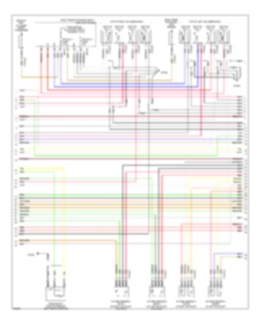
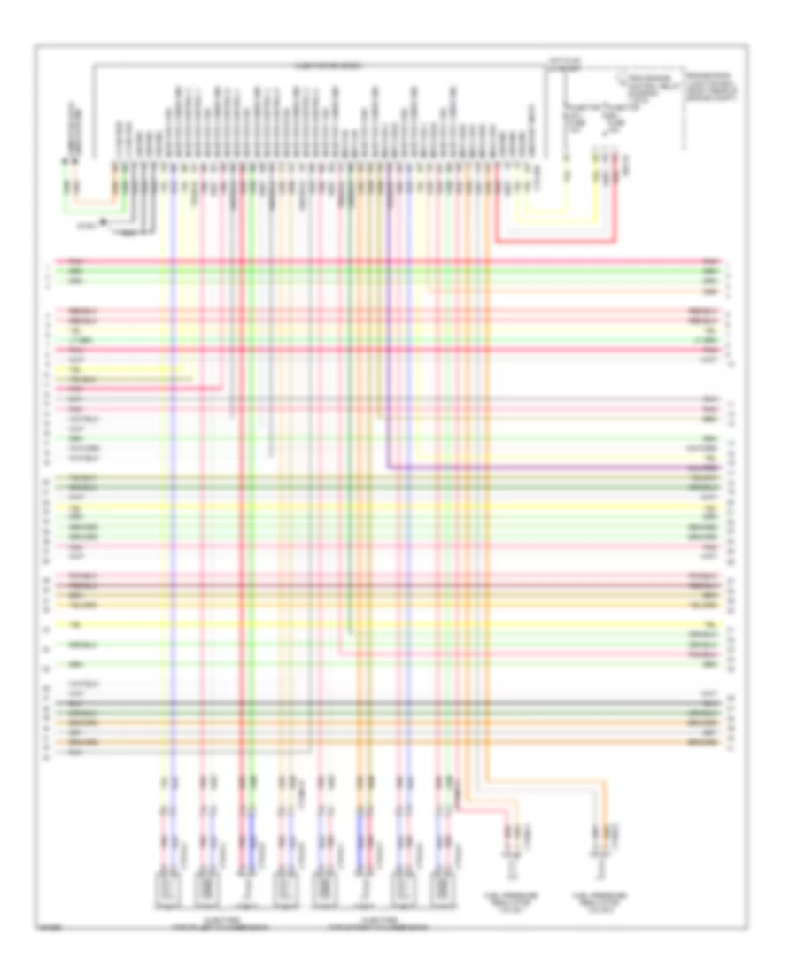
4.6L, Engine Performance Wiring Diagram (3 of 5) for Hyundai Equus Ultimate 2012
 https://portal-diagnostov.com/license.html
Automotive Electricians Portal FZCO
Automotive Electricians Portal FZCO
https://portal-diagnostov.com/license.html
https://portal-diagnostov.com/license.html
Automotive Electricians Portal FZCO
Automotive Electricians Portal FZCOList of elements for 4.6L, Engine Performance Wiring Diagram (3 of 5) for Hyundai Equus Ultimate 2012:
- (diagram 1 of 5)
- (rear of left cylinder bank) condenser
- (right rear of engine compt)
- (right rear of engine) con- denser
- (top of left cylinder bank)
- (top of right cylinder bank)
- Crankshaft position sensor (left rear of engine)
- Ctg16-1
- Ctg16-2
- Ctg16-3
- Ctg16-4
- Ctg18-1
- Ctg18-2
- Ctg18-3
- Ctg18-4
- Ctg18-5
- Ctg18-6
- Ctg18-7
- Ctg18-8
- Ctg19-1
- Ctg19-2
- E/r junction box
- E/r-ca
- E/r-cb
- From engine control relay b
- Gtg02
- Gtg03
- Gtg04
- Ign coil-1 fuse 15a
- Ign coil-2 fuse 15a
- Ignition coil 1
- Ignition coil 2
- Ignition coil 3
- Ignition coil 4
- Ignition coil 5
- Ignition coil 6
- Ignition coil 7
- Ignition coil 8
- Nca
- Oxygen sensor 1 (b1/s1) (on right exhaust manifold)
- Oxygen sensor 2 (b2/s1) (on left exhaust manifold)
- Oxygen sensor 3 (b1/s2) (in right exhaust)
- Oxygen sensor 4 (b2/s2) (in left exhaust)
- Pnk
- Red
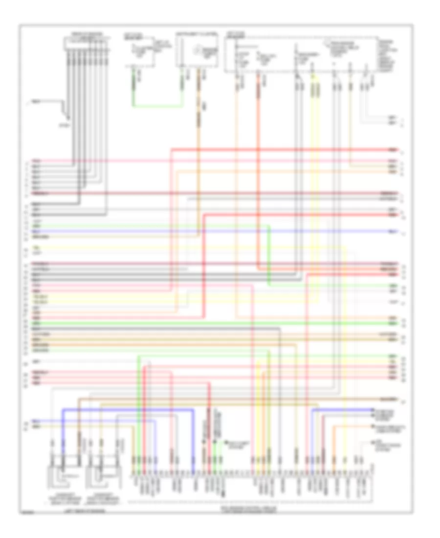
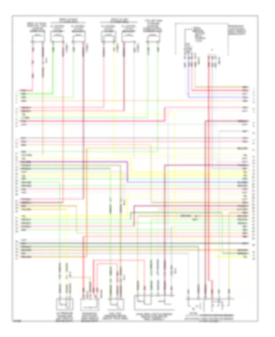
4.6L, Engine Performance Wiring Diagram (4 of 5) for Hyundai Equus Ultimate 2012
 https://portal-diagnostov.com/license.html
Automotive Electricians Portal FZCO
Automotive Electricians Portal FZCO
https://portal-diagnostov.com/license.html
https://portal-diagnostov.com/license.html
Automotive Electricians Portal FZCO
Automotive Electricians Portal FZCOList of elements for 4.6L, Engine Performance Wiring Diagram (4 of 5) for Hyundai Equus Ultimate 2012:
- (left rear of engine)
- (rear of engine) j/c jc11
- A/c comp
- Air conditioning system
- Alt (fr)
- Anti-theft system
- Aps 1 gnd
- Aps 2 gnd
- Aps 2 sig
- Brakes system anti-lock
- Camshaft position sensor (bank 2 exhaust)
- Camshaft position sensor (bank 2 intake)
- Can high
- Can low
- Cluster fuse 10a
- Computer data lines system
- Ctg-k
- Ctg13-3
- Ctg13-4
- Cvvt 3 sig
- Cvvt 4 sig
- E/r-ca
- E/r-cb
- E/r-e1a
- Ecm (engine control module) (left rear of engine compt)
- Ecu (ig1) fuse 10a
- Em31
- Eng snsr-1 fuse 10a
- Engine check ind
- Engine room junction box (right rear of engine compt)
- From engine control relay (diagram 1 of 5)
- Ground
- Gtg01
- Hot in on or start
- Htr
- I/p-lhe
- Immo data
- Instrument cluster
- Left i/p junction box
- M11-a
- M11-b
- Mem pwr
- Nca
- Pnk
- Power
- Red
- Signal
- Signal a
- Signal b
- Starting/ charging system
- Stop lp fuse 10a
- Vss sig
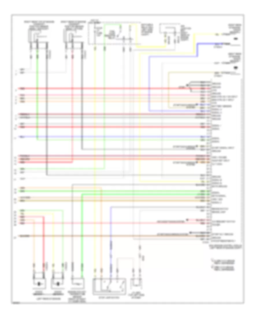
4.6L, Engine Performance Wiring Diagram (5 of 5) for Hyundai Equus Ultimate 2012
 https://portal-diagnostov.com/license.html
Automotive Electricians Portal FZCO
Automotive Electricians Portal FZCO
https://portal-diagnostov.com/license.html
https://portal-diagnostov.com/license.html
Automotive Electricians Portal FZCO
Automotive Electricians Portal FZCOList of elements for 4.6L, Engine Performance Wiring Diagram (5 of 5) for Hyundai Equus Ultimate 2012:
- (left rear of engine)
- (right rear of engine)
- (right rear of engine compt)
- (right rear of engine) camshaft position sensor (bank 1 intake)
- (right rear top of engine) camshaft position sensor (bank 1 exhaust)
- A/c request switch
- Air conditioning system
- Alt (com)
- Aps 1 power
- Aps 1 sig
- Battery sensor
- Box
- Brake lamp
- Brake switch
- Close with brake a
- Ctg-k
- Ctg13-1
- Ctg13-2
- Ctg23-1
- Ctg23-2
- Ctg23-3
- Ctg23-4
- E/r
- E/r fuse & relay box (left side of engine compt)
- E/r-cb
- E/r-e2b
- Ec01
- Ecm (engine control module (left rear of engine compt)
- Ects ground
- Ects signal
- Eng ctrl rly input
- Eng ctrl rly on input
- Engine coolant temperature sensor (front of right cylinder head)
- F/pump resister rly
- Fuel pump
- Ground
- Gtg01
- Hot at all times
- Htr
- J/c je02 (top left side of dash)
- Junction
- Knock
- Knock sensor 2
- Knock sensor 4
- Nca
- On/start input
- Open with brake b
- Pedal depressed
- Pnk
- Power
- Red
- Relay
- Resistor
- Sensor 1
- Sensor 3
- Signal
- Signal 1
- Signal 2
- Signal a
- Signal b
- Start rly ground
- Start signal input
- Starting/charging system
- Stop lamp switch
- Stop lp fuse 10a
5.0L
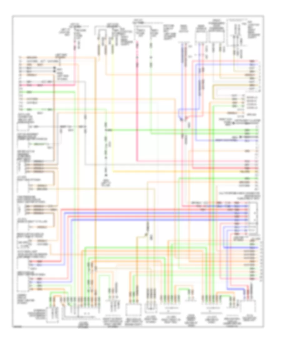
5.0L, Engine Performance Wiring Diagram (1 of 6) for Hyundai Equus Ultimate 2012
 https://portal-diagnostov.com/license.html
Automotive Electricians Portal FZCO
Automotive Electricians Portal FZCO
https://portal-diagnostov.com/license.html
https://portal-diagnostov.com/license.html
Automotive Electricians Portal FZCO
Automotive Electricians Portal FZCOList of elements for 5.0L, Engine Performance Wiring Diagram (1 of 6) for Hyundai Equus Ultimate 2012:
- (left rear of engine compt)
- (not used)
- Anti-theft system
- Apt ground
- Apt signal
- Ccp can high
- Ccp can low
- Ccv output
- Ckps signal a
- Ckps signal b
- Computer data lines system
- Cooling fans system
- Cruise control system
- Cruise ctrl signal
- Cruise sw ground
- Ctg-ag
- Cvvt 1 (intake) signal
- Cvvt 2 (ex) signal
- E/r fuse & relay box (left side of engine compt)
- E/r-ca
- E/r-cb
- E/r-e1a
- E/r-e2a
- E/r-e2b
- Ec41
- Ecm (engine control module)
- Ecu fuse 30a
- Ef11
- Eng ctrl rly ctrl
- Engine control relay
- Engine room junction box (right rear of engine compt)
- Engine speed in
- Etc motor (+)
- Etc motor (-)
- F/pump fuse 20a
- Fan ctrl module pwm
- Fps ground
- From snsr 3 fuse (diagram 5 of 6)
- Ftps gnd
- Ftps signal
- Fuel lvl in (middle)
- Fuel lvl in (total)
- Fuel pump motor
- Fuel pump relay
- Fuel pump resistor (right front wheel well)
- Fuel pump resistor relay
- Fuel pump rly ctrl
- Fuel sender
- Fuel sender & fuel pump motor (under left side of rear seat, in fuel tank)
- Gf03 (base of left "c" pillar)
- Hot at all times
- Ignition coil 1 ctrl
- Ignition coil 2 ctrl
- Ignition coil 3
- Ignition coil 4 ctrl
- Ignition coil 5 ctrl
- Ignition coil 6
- Ignition coil 7 ctrl
- Ignition coil 8 ctrl
- Immo ind control
- Ind control eng chk
- Injector 1 control
- Injector 2 control
- Injector 3 control
- Injector 4 control
- Injector 5 control
- Injector 6 control
- Injector 7 control
- Injector 8 control
- Instrument cluster system
- Map signal
- Map snsr gnd
- Oxygen snsr 1 ground
- Oxygen snsr 1 signal
- Oxygen snsr 2 ground
- Oxygen snsr 2 signal
- Pcsv output
- Pnk
- Power distribution system
- Red
- Snsr 2 fuse 10a
- To ign coil 1 fuse (diagram 3 of 6)
- To injector (b+) fuse (diagram 2 of 6)
- To snsr 3 fuse (diagram 5 of 6)
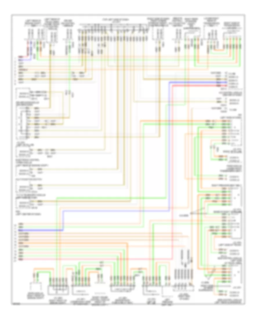
5.0L, Engine Performance Wiring Diagram (2 of 6) for Hyundai Equus Ultimate 2012
 https://portal-diagnostov.com/license.html
Automotive Electricians Portal FZCO
Automotive Electricians Portal FZCO
https://portal-diagnostov.com/license.html
https://portal-diagnostov.com/license.html
Automotive Electricians Portal FZCO
Automotive Electricians Portal FZCOList of elements for 5.0L, Engine Performance Wiring Diagram (2 of 6) for Hyundai Equus Ultimate 2012:
- C-can high
- C-can low
- Computer data lines system
- Ctg-idb
- Ctg02-1
- Ctg02-2
- Ctg24-1
- Ctg24-2
- Ctg24-3
- Ctg24-4
- Ctg24-5
- Ctg24-6
- Ctg24-7
- Ctg24-8
- Ctginj-a
- Ctginj-b
- E/r-cb
- Engine room junction box (right rear of engine compt)
- From engine control relay (diagram 1 of 6)
- Fuel pressure regulator valve 1
- Fuel pressure regulator valve 2
- Ground
- Gtg01
- Hot in on or start
- Injector (b+) fuse 15a
- Injector (ig1) fuse 10a
- Injector 1 sig
- Injector 1 snsr gnd
- Injector 2 sig
- Injector 2 snsr gnd
- Injector 3 sig
- Injector 3 snsr gnd
- Injector 4 sig
- Injector 4 snsr gnd
- Injector 5 sig
- Injector 5 snsr gnd
- Injector 6 sig
- Injector 6 snsr gnd
- Injector 7 sig
- Injector 7 snsr gnd
- Injector 8 sig
- Injector 8 snsr gnd
- Injector control 1
- Injector control 2
- Injector control 3
- Injector control 4
- Injector control 5
- Injector control 6
- Injector control 7
- Injector control 8
- Injector drive box
- Injectors (top of left cylinder bank)
- Injectors (top of right cylinder bank)
- Msv1 high
- Msv1 low
- Msv1 on
- Msv1 sel0
- Msv1 sel1
- Msv2 high
- Msv2 low
- Msv2 on
- Msv2 sel0
- Msv2 sel1
- On/start input
- Pnk
- Red
5.0L, Engine Performance Wiring Diagram (3 of 6) for Hyundai Equus Ultimate 2012
 https://portal-diagnostov.com/license.html
Automotive Electricians Portal FZCO
Automotive Electricians Portal FZCO
https://portal-diagnostov.com/license.html
https://portal-diagnostov.com/license.html
Automotive Electricians Portal FZCO
Automotive Electricians Portal FZCOList of elements for 5.0L, Engine Performance Wiring Diagram (3 of 6) for Hyundai Equus Ultimate 2012:
- (front of left cylinder head)
- (front of right cylinder head)
- (front of trunk, near fuel tank) canister close valve
- (top left side of engine)
- 1 of 6)
- A/c pressure transducer (left front of engine compt)
- Accel pedal position sensor (behind accelerator pedal assembly)
- Canister purge control solenoid valve
- Control relay (diagram
- Ctg05-1
- Ctg05-2
- Ctg05-3
- Ctg05-4
- E/r-ca
- E/r-cb
- E/r-e2a
- Ec41
- Ef11
- Engine room junction box (right rear of engine compt)
- Etc motor & throttle position sensor (throttle body)
- From engine b
- Fuel tank pressure sensor (rear of trunk area)
- Ign coil 1 fuse 20a
- Motor
- Oil control valve 1 (intake)
- Oil control valve 2 (exhaust)
- Oil control valve 3 (intake)
- Oil control valve 4 (exhaust)
- Pnk
- Red
- Throttle position sensor
5.0L, Engine Performance Wiring Diagram (4 of 6) for Hyundai Equus Ultimate 2012
 https://portal-diagnostov.com/license.html
Automotive Electricians Portal FZCO
Automotive Electricians Portal FZCO
https://portal-diagnostov.com/license.html
https://portal-diagnostov.com/license.html
Automotive Electricians Portal FZCO
Automotive Electricians Portal FZCOList of elements for 5.0L, Engine Performance Wiring Diagram (4 of 6) for Hyundai Equus Ultimate 2012:
- (rear of left cylinder bank) condenser
- (right rear of engine) condenser
- (top of left cylinder bank)
- (top of right cylinder bank)
- Crankshaft position sensor (left rear of engine)
- Ctg16-1
- Ctg16-2
- Ctg16-3
- Ctg16-4
- Ctg18-1
- Ctg18-2
- Ctg18-3
- Ctg18-4
- Ctg18-5
- Ctg18-6
- Ctg18-7
- Ctg18-8
- Ctg19-1
- Ctg19-2
- Ctginj-a
- Fuel rail pressure sensor
- Gtg01
- Gtg02
- Gtg03
- Ignition coil 1
- Ignition coil 2
- Ignition coil 3
- Ignition coil 4
- Ignition coil 5
- Ignition coil 6
- Ignition coil 7
- Ignition coil 8
- J/c jc32
- Map sensor
- Nca
- Oxygen sensor 1 (b1/s1) (on right exhaust manifold)
- Oxygen sensor 2 (b2/s1) (on left exhaust manifold)
- Oxygen sensor 3 (b1/s2) (in right exhaust)
- Oxygen sensor 4 (b2/s2) (in left exhaust)
- Pnk
- Red
5.0L, Engine Performance Wiring Diagram (5 of 6) for Hyundai Equus Ultimate 2012
 https://portal-diagnostov.com/license.html
Automotive Electricians Portal FZCO
Automotive Electricians Portal FZCO
https://portal-diagnostov.com/license.html
https://portal-diagnostov.com/license.html
Automotive Electricians Portal FZCO
Automotive Electricians Portal FZCOList of elements for 5.0L, Engine Performance Wiring Diagram (5 of 6) for Hyundai Equus Ultimate 2012:
- (left rear of engine)
- A/c comp cut sig
- Air conditioning system
- Alt fr
- Anti- theft system
- Apm 1 ground
- Apm 2 ground
- Apm 2 signal
- Battery power
- Brakes system anti-lock
- C-can high
- C-can low
- Camshaft position sensor (bank 2 exhaust)
- Camshaft position sensor (bank 2 intake)
- Check ind
- Cluster fuse 10a
- Cmps bank1 signal
- Cmps bank2 ex sig
- Cmps bank2 ground
- Cmps bank2 signal
- Computer data lines
- Computer data lines system
- Ctg-kg
- Ctg13-3
- Ctg13-4
- Cvvt 3 intake sig
- Cvvt 4 ex sig
- E/r-ca
- E/r-cb
- E/r-e1a
- Ec41
- Ecm (engine control module) (left rear of engine compt)
- Ecu (b+) fuse 15a
- Ecu (ig1) fuse 10a
- Em31
- Em41
- Engine
- Engine room junction box (right rear of engine compt)
- From engine control relay (diagram 1 of 6)
- Gtg01
- Hot at all times
- Hot in on or start
- I/p-lhe
- I/p-lhf
- Immo data line
- Instrument cluster
- J/c jc31
- Knock snsr 2 sig a
- Knock snsr 2 sig b
- Knock snsr 4 sig a
- Knock snsr 4 sig b
- Left i/p junction box
- M11-a
- M11-b
- Msv 1 on
- Msv 1 sel 0
- Msv 1 sel 1
- Msv 2 on
- Msv 2 sel 0
- Msv 2 sel 1
- Nca
- Oxy snsr 1 htr
- Oxy snsr 3 signal
- Oxy snsr 4 ground
- Oxy snsr 4 htr
- Pdm 1 fuse 10a
- Pnk
- Red
- Snsr 1 fuse 10a
- Snsr 3 fuse 10a
- Starting/ charging system
- Stop lamp fuse 10a
- System
- To fuel pump relay (diagram 1 of 6)
- Wheel spd sig
5.0L, Engine Performance Wiring Diagram (6 of 6) for Hyundai Equus Ultimate 2012
 https://portal-diagnostov.com/license.html
Automotive Electricians Portal FZCO
Automotive Electricians Portal FZCO
https://portal-diagnostov.com/license.html
https://portal-diagnostov.com/license.html
Automotive Electricians Portal FZCO
Automotive Electricians Portal FZCOList of elements for 5.0L, Engine Performance Wiring Diagram (6 of 6) for Hyundai Equus Ultimate 2012:
- (left rear of engine)
- (left side of engine compt) gtg01
- (right rear
- (right rear of engine)
- (right rear top
- A/c request switch
- Air conditioning system
- Alt com
- Apm 1 power
- Apm 1 signal
- Battery snsr lin line
- Brake lamp
- Brake switch
- Camshaft position sensor (bank 1 intake)
- Close with brake a
- Cmps bank1 ground
- Cmps bank1 signal
- Cmps bank2 ground
- Ctg-kg
- Ctg13-1
- Ctg13-2
- Ctg23-1
- Ctg23-2
- Ctg23-3
- Ctg23-4
- Ec41
- Ecm (engine control module) (left rear of engine compt)
- Em31
- Eng ctrl rly on input
- Engine coolant temperature sensor (front of right cylinder head)
- F/pump resister rly
- Fps power
- Fps signal
- Ground
- Head lamp switch in
- Headlights system
- Its signal
- J/c je02 (top left side of dash)
- Knock sensor 1
- Knock sensor 2
- Knock sensor 3
- Knock sensor 4
- Knock snsr 1 sig a
- Knock snsr 1 signal b
- Knock snsr 3 sig a
- Knock snsr 3 signal b
- Nca
- Of engine)
- Of engine) camshaft position sensor (bank 1 exhaust)
- On/start power
- Open with brake b
- Oxy snsr 2 heater
- Oxy snsr 3 ground
- Oxy snsr 3 heater
- Oxy snsr 4 signal
- Pedal depressed
- Pnk
- Red
- Snsr pwr
- Snsr pwr (tps/map)
- Start rly control
- Start signal input
- Starting/charging system
- Stop lamp relay (engine room fuse & relay box)
- Stop lamp switch
- Tps ground
- Tps signal 1
- Tps signal 2
- Wts ground
- Wts signal
EXTERIOR LIGHTS
Backup Lamps Wiring Diagram for Hyundai Equus Ultimate 2012
 https://portal-diagnostov.com/license.html
Automotive Electricians Portal FZCO
Automotive Electricians Portal FZCO
https://portal-diagnostov.com/license.html
https://portal-diagnostov.com/license.html
Automotive Electricians Portal FZCO
Automotive Electricians Portal FZCOList of elements for Backup Lamps Wiring Diagram for Hyundai Equus Ultimate 2012:
- "c" pillar)
- (base of left
- (behind right side
- (left side of
- B/up
- Back- up lamp relay
- Back-up lamp
- Back-up lamp relay
- C-can high
- C-can low
- Computer data lines system
- Ctg-zf
- E/r fuse & relay box
- E/r junction box (right rear of engine compt)
- E/r-ca
- E/r-cb
- E/r-e2a
- E/r-e2b
- Ef31
- Electro chromic mirror
- Em41
- Engine compt)
- Fr11
- Gf03
- Gf09
- Hot at all times
- Joint connector jf02 (base of left
- Joint connector jf03 (left kick panel)
- Left rear combination lamp
- Lp-1 fuse 10a
- Nca
- Of rear seat)
- Rear curtain module (right side of trunk)
- Right rear combination lamp
- Sport mode switch
- Tcm (transmission control module) (lower right rear of transmission)
- U-drmu
Exterior Lamps Wiring Diagram (1 of 2) for Hyundai Equus Ultimate 2012
 https://portal-diagnostov.com/license.html
Automotive Electricians Portal FZCO
Automotive Electricians Portal FZCO
https://portal-diagnostov.com/license.html
https://portal-diagnostov.com/license.html
Automotive Electricians Portal FZCO
Automotive Electricians Portal FZCOList of elements for Exterior Lamps Wiring Diagram (1 of 2) for Hyundai Equus Ultimate 2012:
- (auto light sensor: top left side of dash)
- (center
- (engine room fuse & relay
- (left end
- (left front of engine compt) esc control module
- (left side of
- (right rear
- (right side
- Auto
- Auto light sensor
- Auto lights
- B-can high
- B-can low
- B-can transceiver
- Battery power
- Box)
- Brake out
- Brk lp
- Brk sw
- Brk sw sig
- Brl 1
- C-can transceiver
- Center facia switch
- Close w/ brake
- Computer data
- Computer data lines system
- Connector
- E/r fuse & relay box
- E/r junction box
- E/r-e1a
- Ec01
- Ecm (engine control module) (left rear of engine compt)
- Elg-a
- Em31
- Em41
- Engine compt)
- Fr02
- Gf10 (behind left side of rear seat)
- Gm01
- Gm01 (left end of dash)
- Gm05
- Ground
- Hazard sw
- Hazard switch
- Hot at all times
- Hot in on or start
- Instrument cluster
- Ipm (instrument panel module) (left side of dash)
- Je01
- Joint
- Joint connector je02 (top left side of dash)
- Joint connector jm03 (right end of dash)
- Joint connector jm05
- Joint connector jr11 (center of trunk lid)
- Left
- Left turn ind
- License lamp
- Light switch
- Lines system
- M/f sw ecu
- M11-a
- M40-a
- M40-b
- M40-c
- Mcu
- Micom
- Multifunction switch
- Nca
- Of dash)
- Of engine compt)
- Off
- Open w/ brake
- Pedal depressed
- Pnk
- Power
- Relay
- Right
- Right turn ind
- Security indicator
- Sensor &
- Signal
- Stop
- Stop lamp relay
- Stop lamp switch
- Stop lp
- Stop lp fuse 10a
- Trunk lid handle switch
- Trunk lid handle switch & license lamp
- Trunk, tailgate, fuel doors system
- Turn signal lamp switch
Exterior Lamps Wiring Diagram (2 of 2) for Hyundai Equus Ultimate 2012
 https://portal-diagnostov.com/license.html
Automotive Electricians Portal FZCO
Automotive Electricians Portal FZCO
https://portal-diagnostov.com/license.html
https://portal-diagnostov.com/license.html
Automotive Electricians Portal FZCO
Automotive Electricians Portal FZCOList of elements for Exterior Lamps Wiring Diagram (2 of 2) for Hyundai Equus Ultimate 2012:
- (driver's
- (front
- (left kick
- (right kick
- (under left
- 10ea)
- 11ea)
- B-can high
- B-can low
- Body unit-1 fuse 10a
- Body unit-2 fuse 10a
- Center of
- Computer data lines system
- D51-b
- D61-b
- Door)
- Driver door module
- E/r junction box (right rear
- E/r-e1a
- E/r-e1b
- E/r-e2a
- Ee21
- Ef11
- Ef21
- Ef31
- Fail fam-b
- Fam
- Fam power-1 fuse 40a
- Fam power-2 fuse 40a
- Fam-a
- Fam-a mem power
- Fam-c
- Fam-c mem power
- Ff01
- Fr02
- Ge04 (lower right rear of engine compt)
- Gf01
- Gf03 (base of left "c" pillar)
- Gf05
- Gf09 (behind right side of rear seat)
- Gf10 (behind left side of rear seat)
- High mounted
- Hot at all times
- Hot in on or start
- I/p-lhf
- I/p-lhg
- J/c je12
- Joint connector je14 (under right side of radiator)
- Joint connector jf02 (base of left "c" pillar)
- Joint connector jf12 (base of right "c" pillar)
- Left head lamp
- Left i/p junction box
- Left power outside
- Left rear combination lamp
- Lr turn sig lp fam-a
- Mirror
- Nca
- Of engine compt)
- Outside mirror
- P/conn fuse 30a
- Panel)
- Passenger door module
- Passenger's
- Pnk
- Power
- Radiator)
- Red
- Right head lamp
- Right power
- Right rear combi- nation lamp
- Right tail lamp fam-c
- Rr turn sig lp fam-a
- Sig lp lf turn
- Sig lp lr turn
- Sig lp rf turn
- Sig lp rr turn
- Stop lamp
- Stop lamp (led 47ea)
- Tail
- Tail lamp (led
- Tail lamp left
- Tell-
- Tell- tail
- Turn lamp
- Turn lamp (led
- Turn lamp (led 11ea)
- Turn lamp (led 6ea)
- Windows system
GROUND DISTRIBUTION
Ground Distribution Wiring Diagram (1 of 6) for Hyundai Equus Ultimate 2012
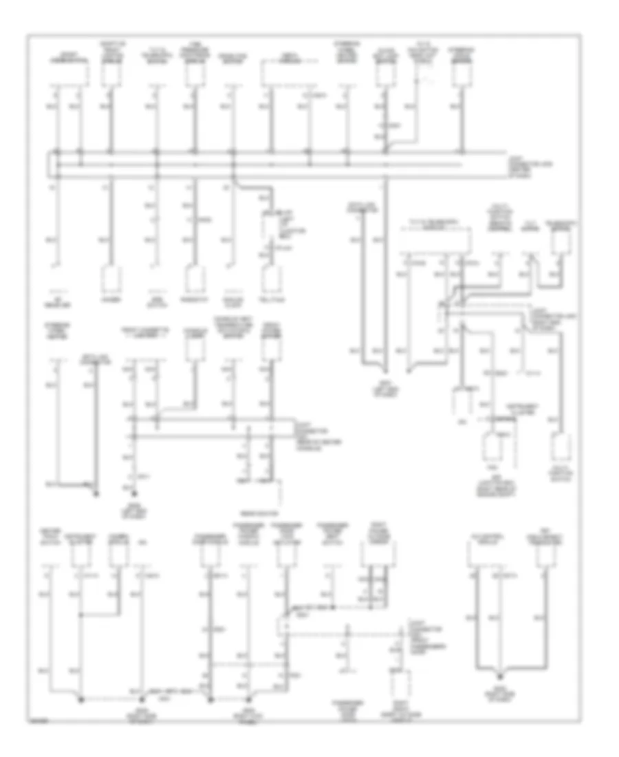 https://portal-diagnostov.com/license.html
Automotive Electricians Portal FZCO
Automotive Electricians Portal FZCO
https://portal-diagnostov.com/license.html
https://portal-diagnostov.com/license.html
Automotive Electricians Portal FZCO
Automotive Electricians Portal FZCOList of elements for Ground Distribution Wiring Diagram (1 of 6) for Hyundai Equus Ultimate 2012:
- A/c control module
- A/v & navigation head unit shield
- Adaptive front lighting module
- Analog clock
- Camera module
- Center facia switch
- Console lamp
- Console vent temperature actuator & switch
- Crash pad switch
- D61-a
- Data link connector
- Dd21
- E/r junction box (right rear of engine compt)
- E/r-e1b
- Em21
- Epb switch
- Fam
- Fam-c
- Fd21
- Fet (field effect transistor)
- Front cigarette lighter
- Front power outlet
- Gf05 (right kick panel)
- Glove box lamp switch
- Gm01 (left end of dash)
- Gm02 (right side of dash)
- Gm05 (right side of dash)
- Gm06 (left end of dash)
- I/p-lhg
- I/p-lhh
- Instrument cluster
- Ionizer
- Ipm
- Joint connector jd21 (front passenger's door)
- Joint connector jm03 (right end of dash)
- Joint connector jm05 (center of dash)
- Joint connector jm21 (rear of center console)
- Left i/p junction box
- M07-a
- M11-a
- M40-a
- M45-a
- M70-a
- M70-b
- Media module
- Mf21
- Mm01
- Mm02
- Mm11
- Multi- function switch
- Multi- function switch (remote control)
- Nca
- Passenger door lock actuator
- Passenger door module
- Passenger power door latch
- Passenger power seat switch
- Passenger power window module
- Rear monitor
- Rf receiver
- Rheostat
- Right front smart outside handle
- Right power outside mirror
- Sport mode switch
- Steering angle sensor
- Steering wheel heated
- Steering wheel heated switch
- Telescopic motor
- Telltale
- Tilt & telescopic module
- Tilt & telescopic switch
- Tilt motor
- Tire pressure monitoring module
Ground Distribution Wiring Diagram (2 of 6) for Hyundai Equus Ultimate 2012
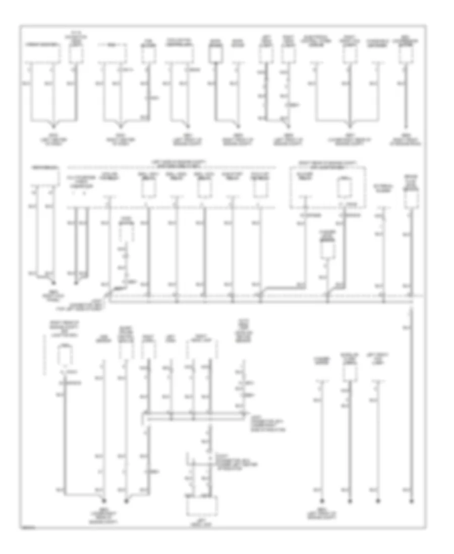 https://portal-diagnostov.com/license.html
Automotive Electricians Portal FZCO
Automotive Electricians Portal FZCO
https://portal-diagnostov.com/license.html
https://portal-diagnostov.com/license.html
Automotive Electricians Portal FZCO
Automotive Electricians Portal FZCOList of elements for Ground Distribution Wiring Diagram (2 of 6) for Hyundai Equus Ultimate 2012:
- (left side of engine compt) e/r fuse & relay box
- (right rear of engine compt) e/r junction box
- A/v & navigation head unit
- Aqs sensor
- Auto head lamp leveling device sensor
- Blower relay
- Brake fluid level sensor
- Burglar alarm horn
- Cooling fan controller
- Cooling fan relay
- E/r-e1b
- E/r-e2b
- E05-b
- Ee21
- Ee31
- Ef31
- Ehps motor
- Ehps noise
- Electronic control wiper module
- Esc compressor motor
- Esc module
- Escl (acc) relay
- Escl (ign1) relay
- Escl (ign2) relay
- External buzzer
- Fam
- Fam-b
- Fam-c
- Fob holder
- Front monitor
- Ge01 (left front of engine compt)
- Ge02 (right kick panel)
- Ge03 (left front of engine compt)
- Ge04 (lower right rear of engine compt)
- Ge05 (right front of engine compt)
- Ge06 (left front of engine compt)
- Ge07 (lower right rear of engine compt)
- Ge08 (right front of engine room)
- Gm03 (left center of dash)
- Gm04 (right center of dash)
- Hood switch
- Joint connector je02 (top left side of dash)
- Joint connector je12 (under left center of radiator
- Joint connector je14 (under right side of radiator)
- Left front fog lamp
- Left head lamp
- Left horn
- M51-a
- Mm01
- Multipurpose check connector
- Nca
- P/outlet (fr) relay
- Pdm
- Right front fog lamp
- Right head lamp
- Right horn
- Smart cruise control module
- Sub start relay
- Washer level sensor
- Washer motor
- Windshield defogger
Ground Distribution Wiring Diagram (3 of 6) for Hyundai Equus Ultimate 2012
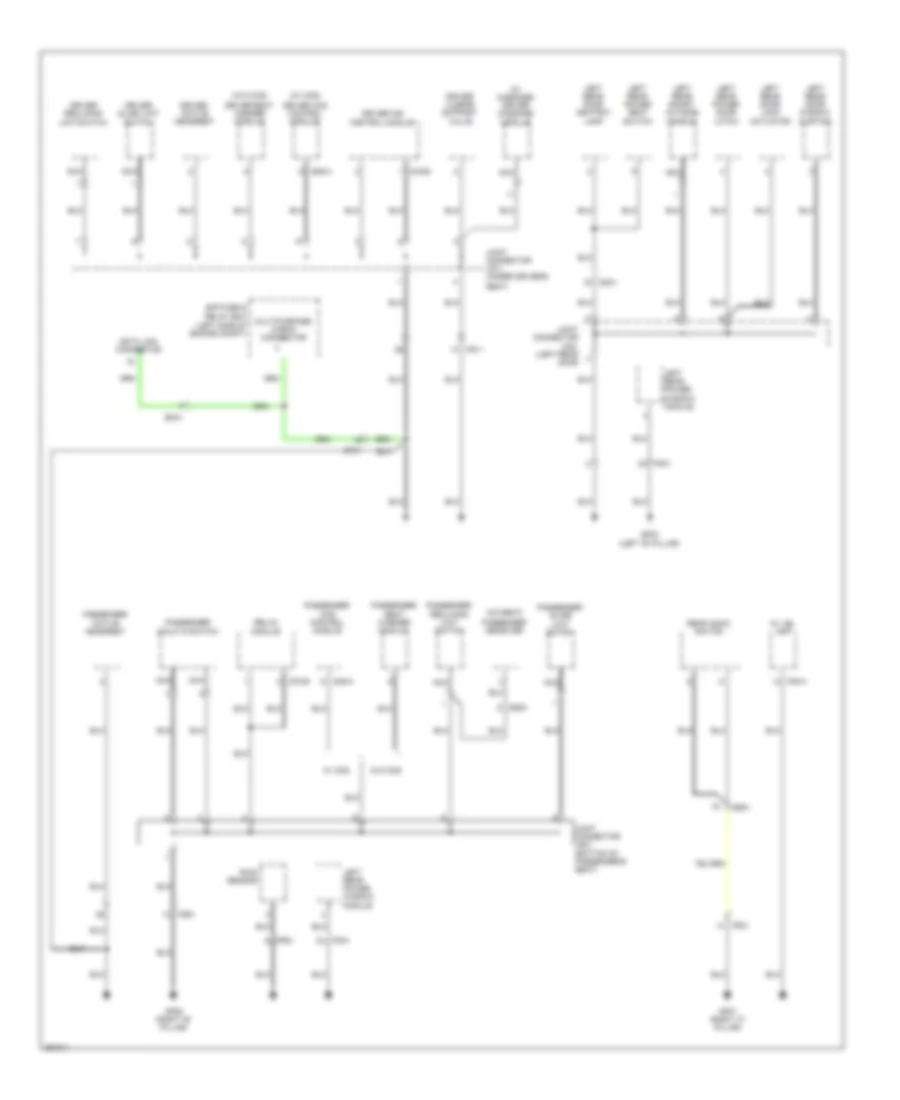 https://portal-diagnostov.com/license.html
Automotive Electricians Portal FZCO
Automotive Electricians Portal FZCO
https://portal-diagnostov.com/license.html
https://portal-diagnostov.com/license.html
Automotive Electricians Portal FZCO
Automotive Electricians Portal FZCOList of elements for Ground Distribution Wiring Diagram (3 of 6) for Hyundai Equus Ultimate 2012:
- (5:5 seat)
- (left side of engine compt)
- (w/ ccs)
- (w/ massage) driver massage module
- (w/o ccs)
- Av jbl amp
- Data link connector
- Dd31
- Driver active headrest
- Driver ccs control module
- Driver ims control module
- Driver lumbar support valve
- Driver reclining limit switch
- Driver seat warmer module
- Driver slide limit switch
- E/r fuse & relay box
- Ef31
- Em41
- F08-a
- Fd31
- Fd41
- Fr21
- Fs11
- Fs31
- Fs51
- Gf02 (left "b" pillar)
- Gf06 (right "b" pillar)
- Gf07 (right "c" pillar)
- Joint connector jd31 (left rear door
- Joint connector js11 (under driver's
- Joint connector js21 (bottom of passenger's seat)
- Left rear door ashtray lamp
- Left rear door lock actuator
- Left rear door window curtain
- Left rear power door latch
- Left rear power seat switch
- Left rear power window module
- Left rear smart outside handle
- Multipurpose check connector
- Nca
- Passenger active headrest
- Passenger ccs control module
- Passenger receiver
- Passenger reclining limit switch
- Passenger seat warmer module
- Passenger slide limit switch
- Passenger walk in switch
- Rain sensor
- Rear audio switch
- Relax module
- S06-a
- S16-b
- S46-a
- S70-b
- Seat)
- Ss21
- Ss51
- W/ ccs
- W/o ccs
Ground Distribution Wiring Diagram (4 of 6) for Hyundai Equus Ultimate 2012
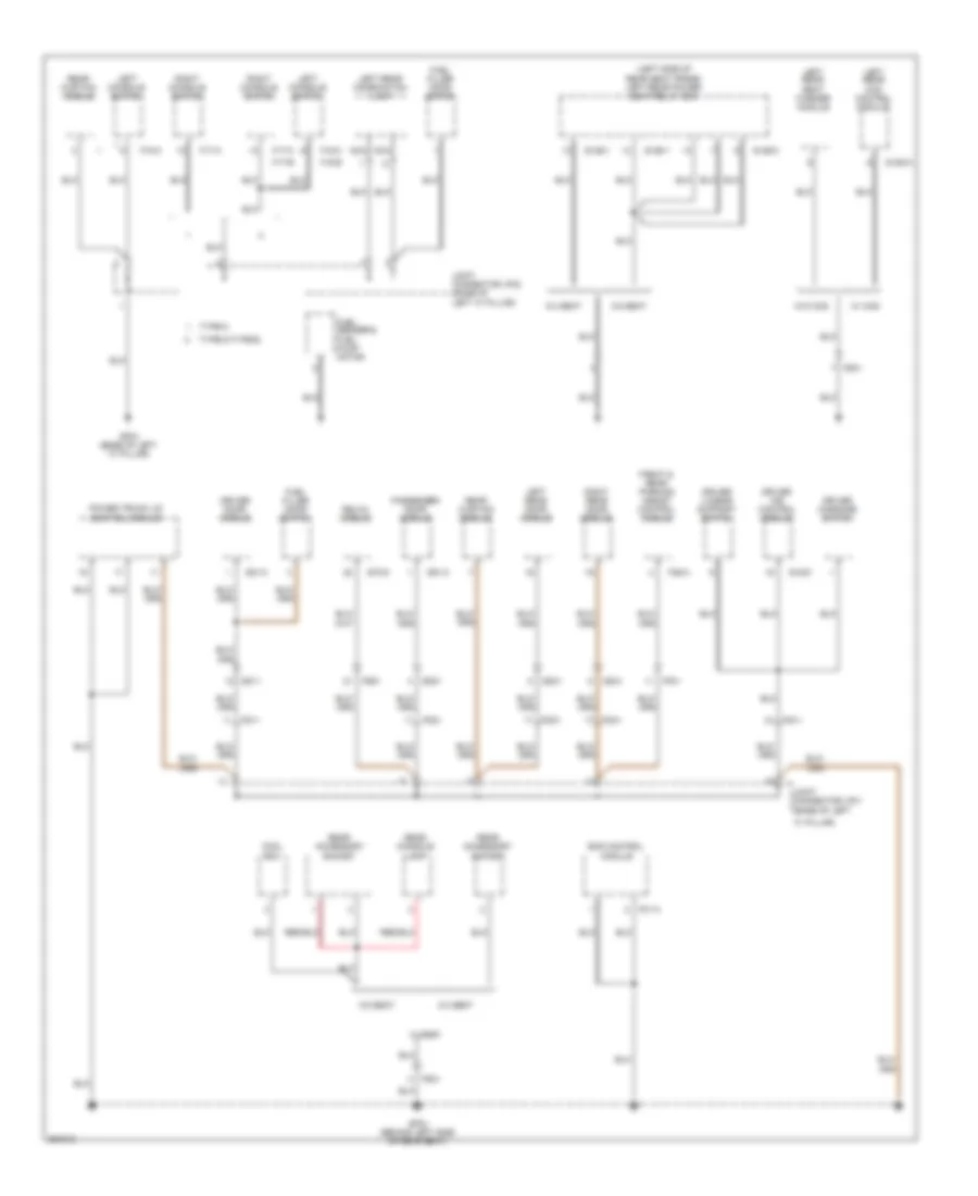 https://portal-diagnostov.com/license.html
Automotive Electricians Portal FZCO
Automotive Electricians Portal FZCO
https://portal-diagnostov.com/license.html
https://portal-diagnostov.com/license.html
Automotive Electricians Portal FZCO
Automotive Electricians Portal FZCOList of elements for Ground Distribution Wiring Diagram (4 of 6) for Hyundai Equus Ultimate 2012:
- "c" pillar)
- (left side of rear seat frame) left rear power seat relay box
- 5:5 seat
- 6:4 seat
- Cool box
- D51-c
- D61-c
- Dd11
- Dd21
- Dd31
- Dd41
- Driver door module
- Driver ims control module
- Driver lumbar support switch
- Driver massage switch
- Ecs control module
- F01-a
- F15-a
- F15-c
- F15-e
- F17-a
- F17-c
- F17-e
- F36-a
- Fd11
- Fd21
- Fd31
- Fd41
- Ff01
- Front & rear parking assist control module
- Fs11
- Fs31
- Fs51
- Fuel filler door motor
- Fuel filler door switch
- Fuel sender & fuel pump motor
- Gf03 (base of left "c" pillar)
- Gf04 (behind left side of rear seat)
- Joint connector jf01 (base of left
- Joint connector jf02 (base of left "c" pillar)
- Left console switch
- Left rear ccs control module
- Left rear combination lamp
- Left rear door module
- Left rear seat warmer module
- Nca
- Passenger door module
- Power trunk lid control module
- Rear accessory socket
- Rear console lamp
- Rear curtain module
- Relax module
- Right console switch
- Right rear door module
- S106-a
- S126-1
- S126-2
- S16-d
- S70-d
- Ss51
- Type-a
- Type-c/type-e
- W/ ccs
- W/o ccs
Ground Distribution Wiring Diagram (5 of 6) for Hyundai Equus Ultimate 2012
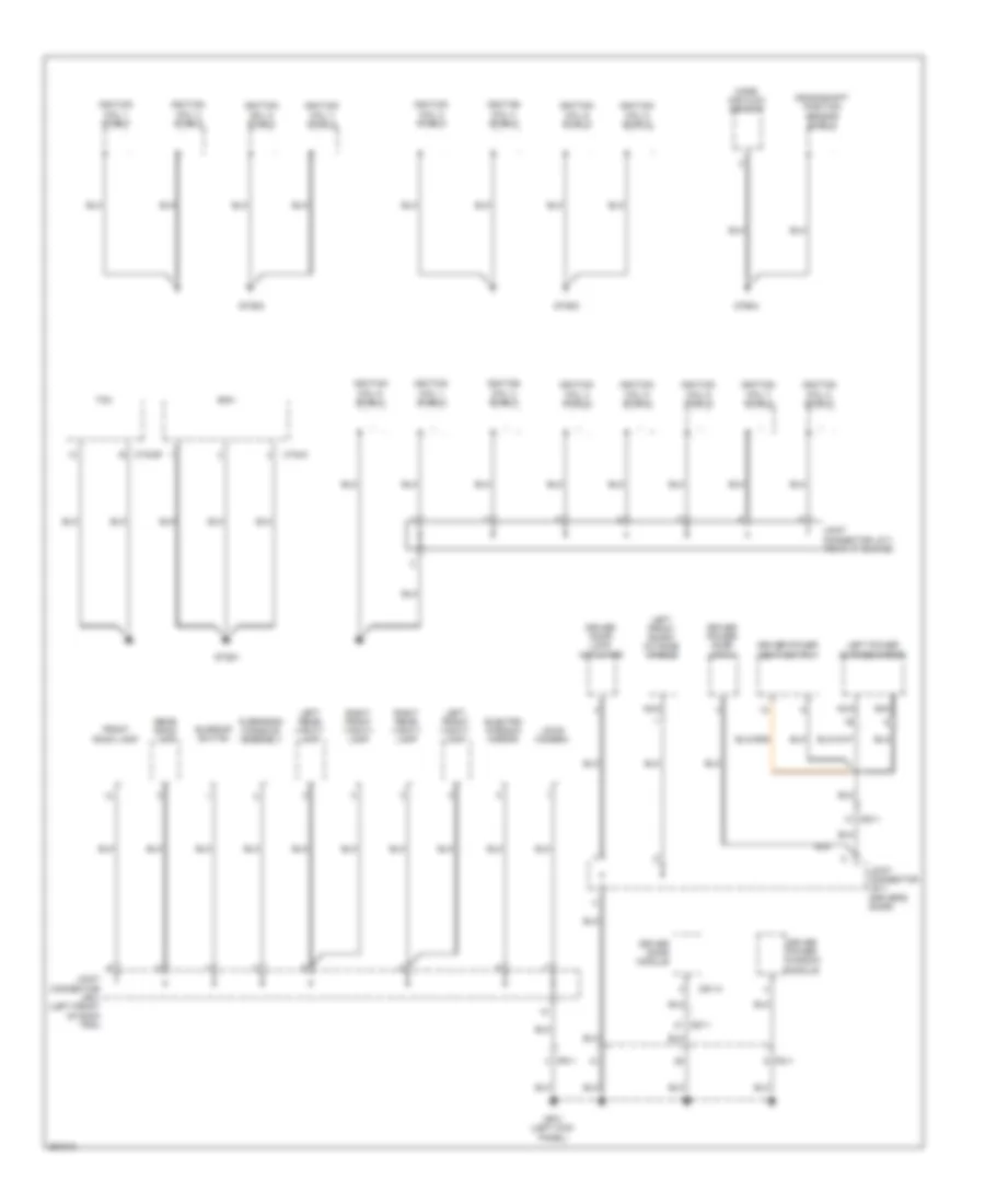 https://portal-diagnostov.com/license.html
Automotive Electricians Portal FZCO
Automotive Electricians Portal FZCO
https://portal-diagnostov.com/license.html
https://portal-diagnostov.com/license.html
Automotive Electricians Portal FZCO
Automotive Electricians Portal FZCOList of elements for Ground Distribution Wiring Diagram (5 of 6) for Hyundai Equus Ultimate 2012:
- Crankshaft position sensor shield
- Ctg-k
- Ctg-zf
- D51-a
- Dd11
- Driver door lock actuator
- Driver door module
- Driver power door latch
- Driver power seat switch
- Driver power window module
- Ecm
- Electro chromic mirror
- Fd11
- Fr11
- Front room lamp
- Gf01 (left kick panel)
- Gtg01
- Gtg02
- Gtg03
- Gtg04
- Ignition coil 1 shield
- Ignition coil 2 shield
- Ignition coil 3 shield
- Ignition coil 4 shield
- Ignition coil 5 shield
- Ignition coil 6 shield
- Ignition coil 7 shield
- Ignition coil 8 shield
- Joint connector jc11 (rear of engine)
- Joint connector jd11 (driver's door)
- Joint connector jr01 (left front of roof trim)
- Ldws camera
- Left front smart outside handle
- Left front vanity lamp
- Left power outside mirror
- Left rear vanity lamp
- Mass air flow sensor
- Nca
- Overhead console assembly
- Rear room lamp
- Right front vanity lamp
- Right rear vanity lamp
- Sunroof switch
- Tcm
Ground Distribution Wiring Diagram (6 of 6) for Hyundai Equus Ultimate 2012
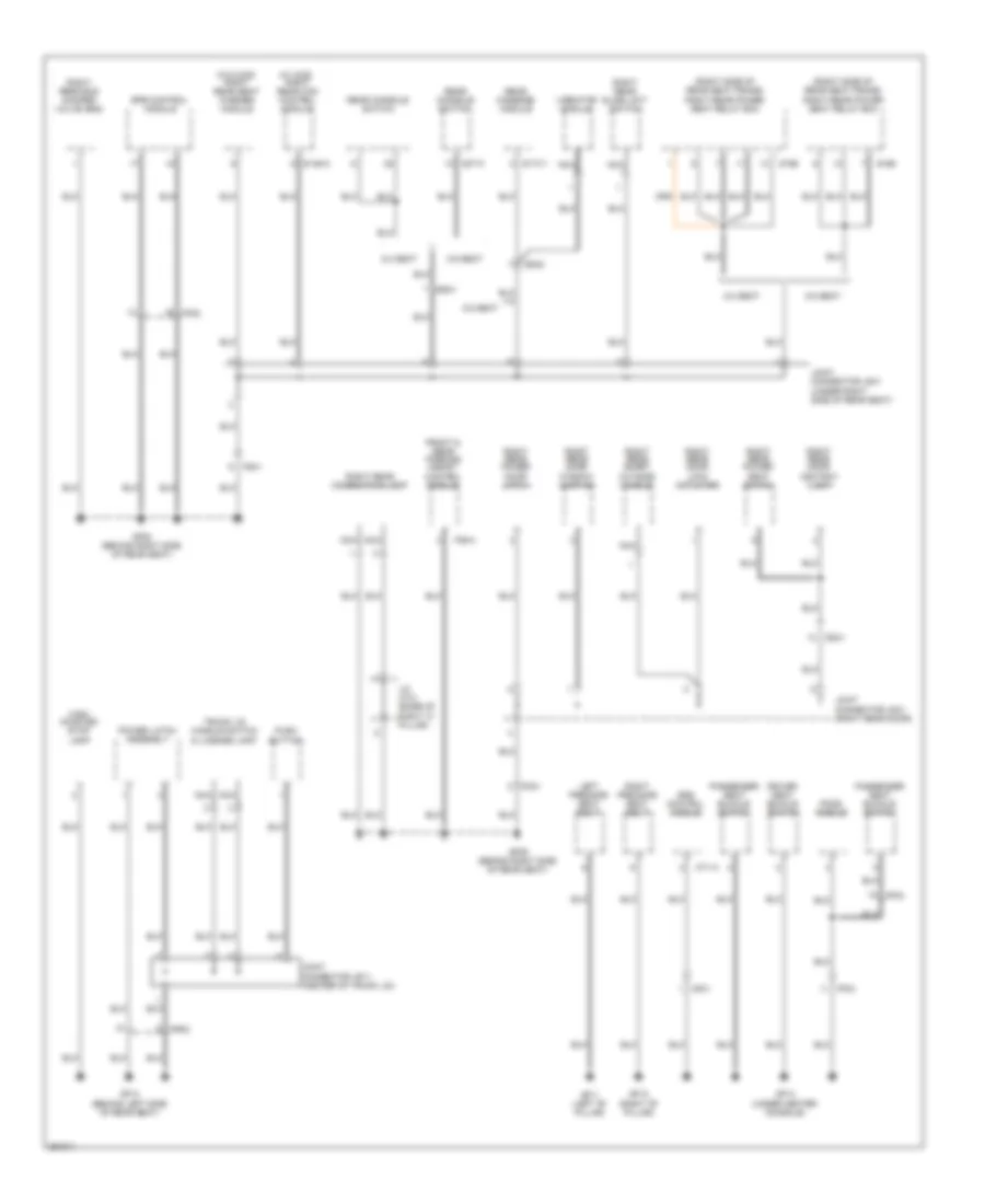 https://portal-diagnostov.com/license.html
Automotive Electricians Portal FZCO
Automotive Electricians Portal FZCO
https://portal-diagnostov.com/license.html
https://portal-diagnostov.com/license.html
Automotive Electricians Portal FZCO
Automotive Electricians Portal FZCOList of elements for Ground Distribution Wiring Diagram (6 of 6) for Hyundai Equus Ultimate 2012:
- (right side of rear seat frame) right rear power seat relay box
- (w/ ccs) right rear ccs control module
- (w/o ccs) right rear seat warmer module
- 5:5 seat
- 6:4 seat
- Dd41
- Driver seat buckle switch
- Epb control module
- F36-a
- Fd41
- Ff02
- Ff03
- Fr02
- Front & rear parking assist control module
- Fs41
- Gf08 (behind right side of rear seat)
- Gf09 (behind right side of rear seat)
- Gf10 (behind left side of rear seat)
- Gf11 (left "b" pillar)
- Gf12 (right "b" pillar)
- Gf13 (under center console)
- High- mounted stop lamp
- J/c jf12 (base of
- Joint connector jd41 (right rear door)
- Joint connector jr11 (center of trunk lid)
- Joint connector js41 (under right side of rear seat)
- Left pre-safe seat belt
- M71-a
- Mf01
- Nca
- Passenger seat buckle switch
- Pods module
- Power latch assembly
- Push button
- Rear console switch
- Rear massage module
- Right "c" pillar)
- Right pre-safe seat belt
- Right rear combination lamp
- Right rear door ashtray lamp
- Right rear door lock actuator
- Right rear door window curtain
- Right rear ecs damper valve (gnd)
- Right rear power door latch
- Right rear power seat switch
- Right rear slide limit switch
- Right rear smart outside handle
- S146-a
- S166
- S174-1
- S37-a
- Srs control module
- Ss41
- Ss42
- Trunk lid handle switch & license lamp
- Vibrator module
HEADLIGHTS
Adaptive Front Lighting Wiring Diagram for Hyundai Equus Ultimate 2012
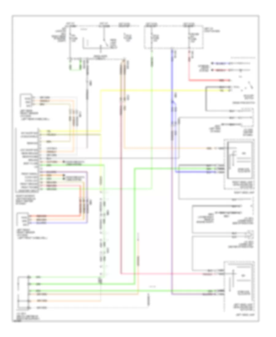 https://portal-diagnostov.com/license.html
Automotive Electricians Portal FZCO
Automotive Electricians Portal FZCO
https://portal-diagnostov.com/license.html
https://portal-diagnostov.com/license.html
Automotive Electricians Portal FZCO
Automotive Electricians Portal FZCOList of elements for Adaptive Front Lighting Wiring Diagram for Hyundai Equus Ultimate 2012:
- rear sig
- (left front wheelwell)
- (left rear wheelwell)
- (right rear
- (w/o ecs)
- Adaptive front lighting module (right center of dash)
- Afls fuse 10a
- Afls off switch
- Body k-line
- C-can high
- C-can low
- Compt)
- Computer data lines system
- Crash pad switch
- Cruise sw fuse 10a
- E/r junction box
- E/r-e2a
- E/r-e2b
- Ee21
- Em21
- Em31
- Em41
- Front ground
- Front power
- Front signal
- Ge04 (lower right rear of engine compt)
- Gm01 (left end of dash)
- Gnd
- Ground
- Head lamp (low) relay
- Headlamps circuit
- Hot at all times
- Hot in on or start
- I/p-lha
- I/p-lhc
- Ill
- Interior lights system
- Ipm fuse 10a
- Ism
- J/c je12 (under left center of radiator)
- J/c je13 (below center of radiator support)
- J/c je14 (under right side of radiator)
- J/c jm05 (center of dash)
- Left front height sensor
- Left head lamp
- Left head lamp leveling device actuator
- Left i/p junction box
- Left rear height sensor (w/o ecs)
- Lin
- Lin bus shield
- Low on/off sig
- Mf11
- Nca
- Of engine
- On/start input
- Pwr
- Rear ground
- Rear power
- Red
- Right head lamp
- Right head lamp leveling device actuator
- Sig
- Step mtr hlld actr
- Sw on/off sig
Headlamps Wiring Diagram for Hyundai Equus Ultimate 2012
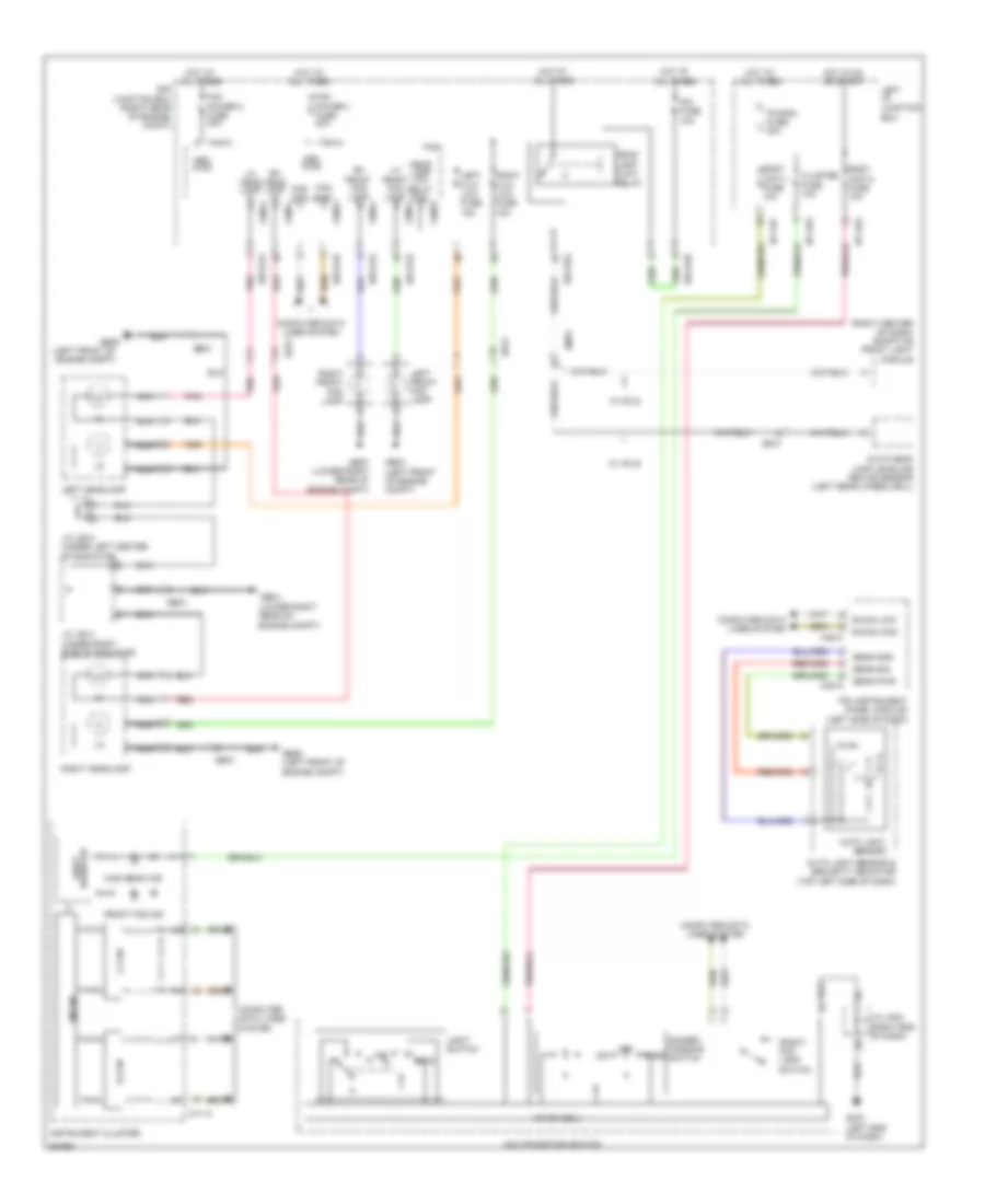 https://portal-diagnostov.com/license.html
Automotive Electricians Portal FZCO
Automotive Electricians Portal FZCO
https://portal-diagnostov.com/license.html
https://portal-diagnostov.com/license.html
Automotive Electricians Portal FZCO
Automotive Electricians Portal FZCOList of elements for Headlamps Wiring Diagram for Hyundai Equus Ultimate 2012:
- (left front of engine compt)
- (lower right rear of engine compt)
- (right center of dash) adaptive front light module
- (right rear
- Auto
- Auto head lamp leveling device sensor (left rear wheelwell)
- Auto light sensor
- Auto light sensor & security indicator (top left side of dash)
- B-can
- B-can high
- B-can low
- Body unit-1 fuse 10a
- Body unit-2 fuse 10a
- C-can
- Can high
- Can low
- Cluster fuse 10a
- Compt)
- Computer data lines system
- Dim
- Dimmer/ passing switch
- E/r
- E/r-e1a
- E/r-e1b
- E/r-e2a
- E/r-e2b
- Ee21
- Ee31
- Ef31
- Em31
- Fam
- Fam power 1 fuse 40a
- Fam power 2 fuse 40a
- Fam-a
- Fam-b
- Fam-c
- Front fog ind
- Front fog lamp switch
- Ge03 (left front of engine compt)
- Ge04
- Ge06
- Ge06 (left front of engine compt)
- Ge07 (lower right rear of engine compt)
- Gm01 (left end of dash)
- Head lamp (low)
- Head lamp low relay ctrl
- High beam ind
- Hot at all times
- Hot in on or start
- I/p-lhe
- I/p-lhf
- I/p-lhg
- Instrument cluster
- Ipm (instrument panel module) (left side of dash)
- Ipm fuse 10a
- J/c je12 (under left center of radiator)
- J/c je14 (under right side of radiator)
- J/c jm03 (right end of dash)
- Junction box
- Left front fog lamp
- Left h/lp low fuse 15a
- Left headlamp
- Left i/p junction box
- Lh front fog lamp
- Lh head lamp hi
- Light switch
- M/f sw ecu
- M11-a
- M40-a
- M40-c
- Mem pwr
- Micom
- Multifunction switch
- Nca
- Of engine
- Off
- P/conn fuse 30a
- Pass
- Pnk
- Red
- Relay
- Resistor shift
- Rh front fog lamp
- Rh head lamp hi
- Right front fog lamp
- Right h/lp low fuse 15a
- Right headlamp
- Sens gnd
- Sens pwr
- Sens sig
- W/ afls
Headlamps Leveling Wiring Diagram for Hyundai Equus Ultimate 2012
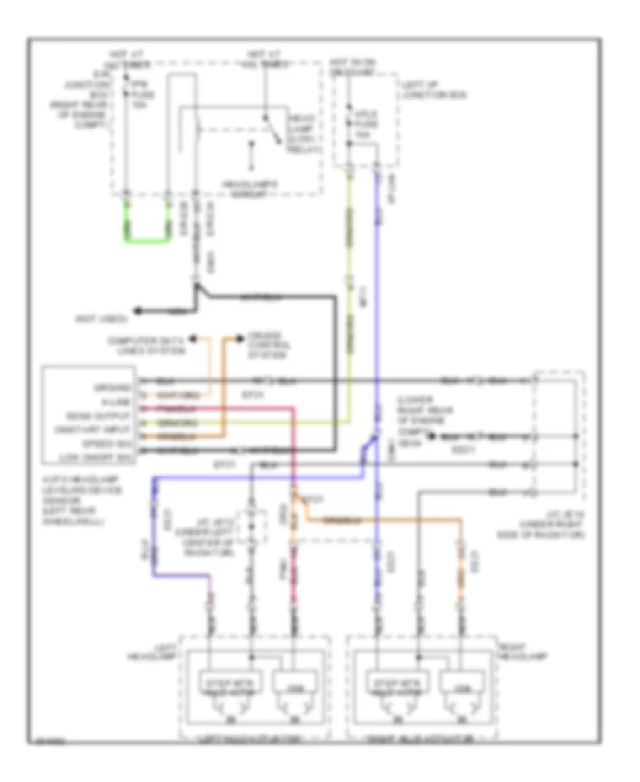 https://portal-diagnostov.com/license.html
Automotive Electricians Portal FZCO
Automotive Electricians Portal FZCO
https://portal-diagnostov.com/license.html
https://portal-diagnostov.com/license.html
Automotive Electricians Portal FZCO
Automotive Electricians Portal FZCOList of elements for Headlamps Leveling Wiring Diagram for Hyundai Equus Ultimate 2012:
- (lower right rear of engine compt)
- (not used)
- (right rear
- Afls fuse 10a
- Auto headlamp leveling device sensor (left rear wheelwell)
- Compt)
- Computer data lines system
- Cruise control system
- E/r junction box
- E/r-e2a
- E/r-e2b
- Ee21
- Ef21
- Ef31
- Em31
- Em41
- Ge04
- Ground
- Head lamp (low) relay
- Headlamp
- Headlamps circuit
- Hot at all times
- Hot in on or start
- I/p-lha
- Ipm fuse 10a
- Ism
- J/c je12 (under left center of radiator)
- J/c je14 (under right side of radiator)
- K-line
- Left
- Left hlld actuator
- Left i/p junction box
- Low on/off sig
- Mf11
- Nca
- Of engine
- On/start input
- Pnk/
- Right
- Right hlld actuator
- Sens output
- Speed sig
- Step mtr hlld actr
HORN
Horn Wiring Diagram for Hyundai Equus Ultimate 2012
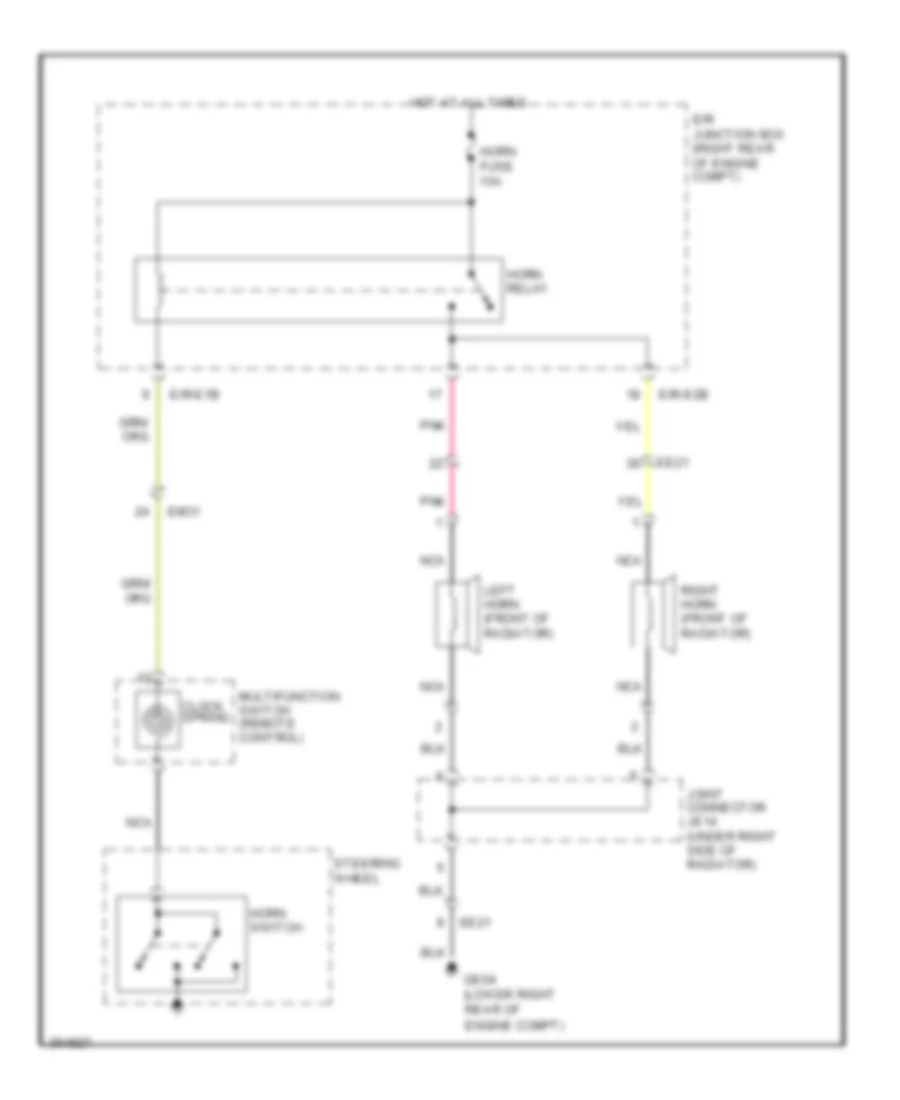 https://portal-diagnostov.com/license.html
Automotive Electricians Portal FZCO
Automotive Electricians Portal FZCO
https://portal-diagnostov.com/license.html
https://portal-diagnostov.com/license.html
Automotive Electricians Portal FZCO
Automotive Electricians Portal FZCOList of elements for Horn Wiring Diagram for Hyundai Equus Ultimate 2012:
- (lower right
- Clock spring
- E/r junction box (right rear of engine compt)
- E/r-e1b
- E/r-e2b
- Ee21
- Em31
- Engine compt)
- Ge04
- Horn fuse 15a
- Horn relay
- Horn switch
- Hot at all times
- Joint connector je14 (under right side of
- Left horn (front of radiator)
- Multifunction switch (remote control)
- Nca
- Pnk
- Radiator)
- Rear of
- Right horn (front of radiator)
- Steering wheel
INSTRUMENT CLUSTER
Instrument Cluster Wiring Diagram (1 of 2) for Hyundai Equus Ultimate 2012
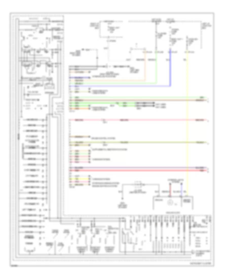 https://portal-diagnostov.com/license.html
Automotive Electricians Portal FZCO
Automotive Electricians Portal FZCO
https://portal-diagnostov.com/license.html
https://portal-diagnostov.com/license.html
Automotive Electricians Portal FZCO
Automotive Electricians Portal FZCOList of elements for Instrument Cluster Wiring Diagram (1 of 2) for Hyundai Equus Ultimate 2012:
- (-) bag air
- (not used)
- 24v reg
- 3v reg
- 5v reg
- 9v reg
- A/con (b+) fuse 10a
- Abs ind
- Afls off ind
- Air bag ind
- Air bag (+)
- Analog clock
- Auto hold ind (green)
- Auto hold ind (white)
- Body unit 1 fuse 10a
- Body unit fuse 10a
- Cluster fuse 10a
- Computer data lines system
- Constant current circuit
- Constant-current circuit
- Cruise control system
- Cruise ind
- Cruise set ind
- Dial gradation ill (4ea led)
- Dial ill (4ea led)
- Door open ind
- Ecs ind
- Ee21
- Em21
- Em41
- Engine controls system
- Epb ind
- Esc ind
- Esc off ind
- Front fog ind
- Fuel gauge
- Fuel gnd
- Gm01 (left end of dash)
- Gm05 (right side of dash)
- Ground
- High beam ind
- Hot at all times
- Hot in on
- Hot in on or start
- I/p-lha
- I/p-lhe
- I/p-lhf
- I/p-rhd
- Ill
- Ill (+)
- Ill (-)
- Immo ind
- Instrument cluster
- Interior lights system
- J/c jm03 (right end of dash)
- J/c jm05 (center of dash)
- Lcd led
- Left i/p junction box
- Left turn ind
- Low fuel ind
- M01-b
- M11-a
- M11-b
- Memory power
- Mf11
- Micom
- Nca
- On input
- On/start input
- Over speed ind
- P gnd
- P/conn fuse 30a
- Parking brake
- Parking brake ind
- Pnk
- Pointer lcd ill (6ea led)
- Psb ind
- Red
- Right i/p junction box
- Right turn ind
- Rom
- S gnd
- Seat belt ind
- Shift resistor
- Sig fuel
- Sound chip
- Speaker
- Speedo meter
- Starting/charging system
- Tacho meter
- Tail on ind
- Temp gauge
- Tft lcd driver
- Tft lcd panel
- To indicators (diagram 2 of 2)
- Tpms fl
- Tpms fr
- Tpms rl
- Tpms rr
- Trunk open ind
- Vsm off ind
- Warning systems
- Washer low
- Washer low ind
Instrument Cluster Wiring Diagram (2 of 2) for Hyundai Equus Ultimate 2012
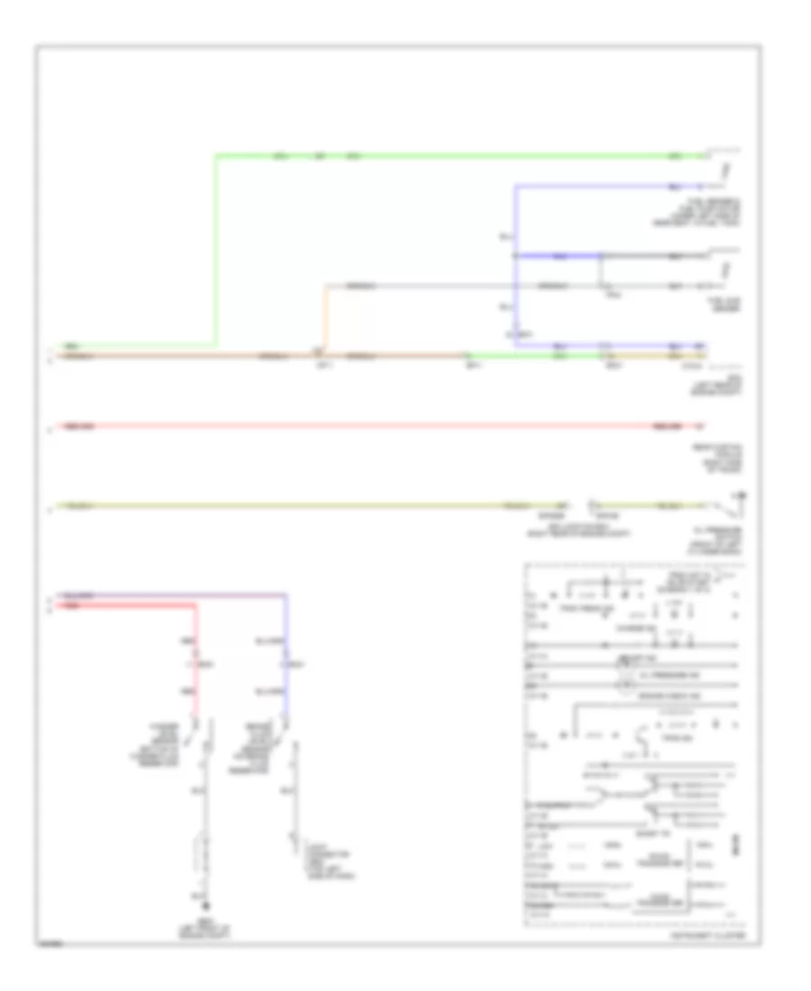 https://portal-diagnostov.com/license.html
Automotive Electricians Portal FZCO
Automotive Electricians Portal FZCO
https://portal-diagnostov.com/license.html
https://portal-diagnostov.com/license.html
Automotive Electricians Portal FZCO
Automotive Electricians Portal FZCOList of elements for Instrument Cluster Wiring Diagram (2 of 2) for Hyundai Equus Ultimate 2012:
- 4p out
- B-can transceiver
- Brake fluid level sensor (on brake fluid reservoir)
- C-can transceiver
- Charge ind
- Ctg-a
- E/r junction box (right rear of engine compt)
- E/r-cb
- E/r-e2b
- Ec01
- Ecm (left rear of engine compt)
- Ef11
- Ef31
- Em21
- Em31
- Engine check ind
- Ff04
- From hot in a on or start (diagram 1 of 2)
- Fuel sender & fuel pump motor (under left side of rear seat, in fuel tank)
- Fuel sub sender
- Ge03 (left front of engine compt)
- High
- Instrument cluster
- Joint connector je02 (top left side of dash)
- Led off ind
- Low
- M11-a
- M11-b
- Mf11
- Micom
- Oil pressure ind
- Oil pressure switch (front of left cylinder bank)
- P output
- Rear curtain module (right side of trunk)
- Red
- Smart tr
- Tpms ind
- Tpms tread ind
- Washer level sensor (bottom of washer fluid reservoir)
INTERIOR LIGHTS
Courtesy Lamps Wiring Diagram (1 of 3) for Hyundai Equus Ultimate 2012
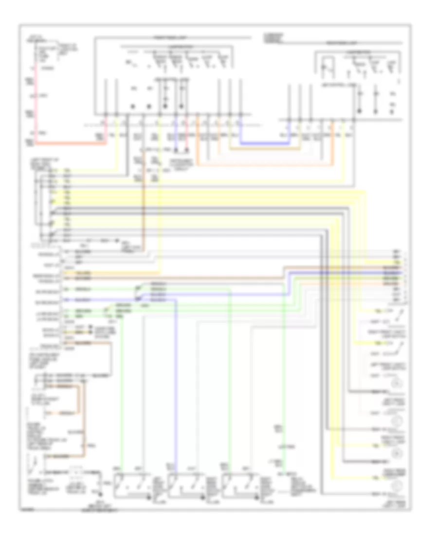 https://portal-diagnostov.com/license.html
Automotive Electricians Portal FZCO
Automotive Electricians Portal FZCO
https://portal-diagnostov.com/license.html
https://portal-diagnostov.com/license.html
Automotive Electricians Portal FZCO
Automotive Electricians Portal FZCOList of elements for Courtesy Lamps Wiring Diagram (1 of 3) for Hyundai Equus Ultimate 2012:
- (left front of roof trim) j/c jr01
- B-can hi
- B-can lo
- Computer data lines system
- Door
- Foot lp
- Fr room lp
- Fr02
- Fr11
- Fr21
- Front room
- Front room lamp
- Fs52
- Gf01 (left kick panel)
- Gf10 (behind left side of rear seat)
- Hot in acc or on
- I/p-rhd
- Ill
- Instrument illumination circuit
- Ipm (instrument panel module) (left side of dash)
- J/c jf11 (base of right "c" pillar)
- J/c jr11 (center of trunk lid)
- Lamp switch
- Led control logic
- Left front door switch (left "b" pillar)
- Left front vanity lamp
- Left front vanity lamp switch
- Left rear vanity lamp
- Lh fr dr sw
- Lh rr dr sw
- M40-a
- M40-b
- M40-c
- Map lh
- Map rh
- Mf11
- Mf21
- Overhead console assembly
- P/outlet (fr) fuse 10a
- Power latch assembly (center rear of trunk lid)
- Power trunk lid control module (w/ power trunk lid) (left rear of trunk area)
- Rear room
- Rear room lamp
- Rear room lp
- Relax module (bottom of passenger's seat)
- Rh fr dr sw
- Rh rr dr sw
- Right front door switch (right "b" pillar)
- Right front vanity lamp
- Right front vanity lamp switch
- Right i/p junction box
- Right rear door switch (right "c" pillar)
- Right rear vanity lamp
- Room
- S70-d
- Tr room lp
- Trunk sw
Courtesy Lamps Wiring Diagram (2 of 3) for Hyundai Equus Ultimate 2012
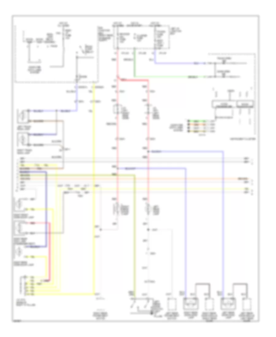 https://portal-diagnostov.com/license.html
Automotive Electricians Portal FZCO
Automotive Electricians Portal FZCO
https://portal-diagnostov.com/license.html
https://portal-diagnostov.com/license.html
Automotive Electricians Portal FZCO
Automotive Electricians Portal FZCOList of elements for Courtesy Lamps Wiring Diagram (2 of 3) for Hyundai Equus Ultimate 2012:
- B-can high
- B-can low
- B-can transceiver
- Body unit 1 fuse 10a
- C-can transceiver
- Cluster fuse 10a
- Computer data lines system
- Dd31
- Dd41
- Diode
- Door open ind
- E/r junction box (right rear of engine compt)
- E/r-e1a
- E/r-e2a
- Ef11
- Ef21
- Ef31
- Fam
- Fam-b
- Fd31
- Fd41
- Fr21
- Fs51
- High
- Hot at all times
- Hot in on or start
- I/p-lhc
- I/p-lhe
- I/p-lhf
- Instrument cluster
- J/c jd31 (left rear door)
- J/c jd41 (right rear door)
- J/c jf12 (base of right "c" pillar)
- Left i/p junction box
- Left rear door lamp
- Left rear door module (left rear door)
- Left rear door mood lamp
- Left rear door switch (left "c" pillar)
- Left rear power seat switch
- Left trunk room lamp
- Low
- M11-a
- Mf11
- Micom
- P/conn fuse 30a
- Red
- Right front door scuff lamp
- Right rear door lamp
- Right rear door module (right rear door)
- Right rear door mood lamp
- Right rear door scuff lamp
- Right rear foot lamp (passenger seat)
- Right rear power seat switch
- Right trunk room lamp
- Room lamp relay
- Room lamp relay control
- Room lp fuse 10a
- Rr door mdl fuse 10a
- Trunk open ind
Courtesy Lamps Wiring Diagram (3 of 3) for Hyundai Equus Ultimate 2012
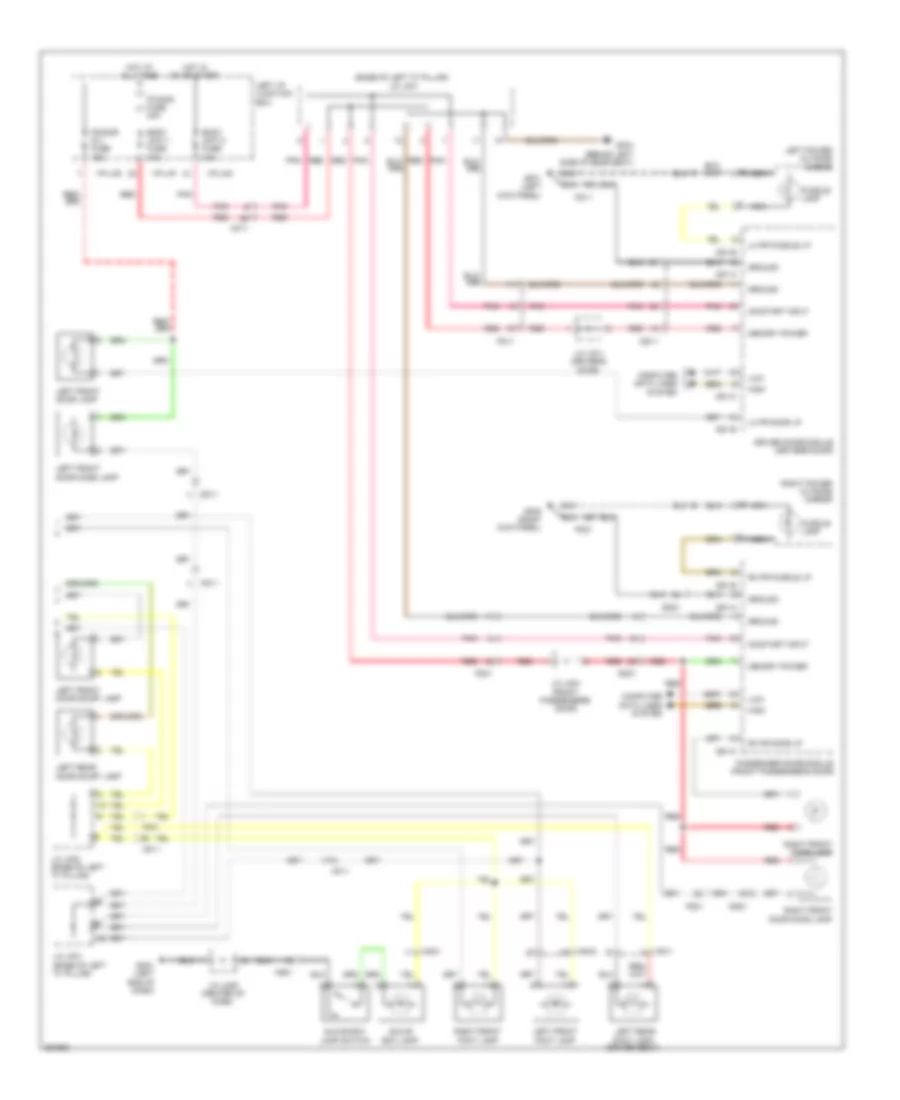 https://portal-diagnostov.com/license.html
Automotive Electricians Portal FZCO
Automotive Electricians Portal FZCO
https://portal-diagnostov.com/license.html
https://portal-diagnostov.com/license.html
Automotive Electricians Portal FZCO
Automotive Electricians Portal FZCOList of elements for Courtesy Lamps Wiring Diagram (3 of 3) for Hyundai Equus Ultimate 2012:
- (base of left "c" pillar) j/c jf01
- Body unit-1 fuse 10a
- Body unit-2 fuse 10a
- Computer data lines system
- D51-a
- D51-b
- D51-c
- D61-a
- D61-b
- D61-c
- Dd11
- Dd21
- Door)
- Driver door module (driver's door)
- Fd11
- Fd21
- Ff01
- Foot lamp (driver seat)
- Fs11
- Gf01 (left kick panel)
- Gf04 (behind left side of rear seat)
- Gf05 (right kick panel)
- Glove box lamp
- Glove box lamp switch
- Gm01 (left end of dash)
- Ground
- High
- Hot at all times
- Hot in on or start
- I/p-lhf
- I/p-lhg
- J/c jd11 (driver's door)
- J/c jd21 (front passenger's
- J/c jf01 (base of left "c" pillar)
- J/c jf02 (base of left "c" pillar)
- J/c jm05 (center of dash)
- Left front door lamp
- Left front door mood lamp
- Left front door scuff lamp
- Left front foot lamp
- Left i/p junction box
- Left power outside mirror
- Left rear
- Left rear door scuff lamp
- Lh fr door lp
- Lh fr puddle lp
- Low
- Memory power
- Mf11
- Mm01
- Mm02
- Nca
- On/start input
- P/conn fuse 30a
- P/door (fl) fuse 15a
- Passenger door module (front passenger's door)
- Pnk
- Puddle lamp
- Red
- Rh fr door lp
- Rh fr puddle lp
- Right front door lamp
- Right front door mood lamp
- Right front foot lamp
- Right power outside mirror
Instrument Illumination Wiring Diagram (1 of 3) for Hyundai Equus Ultimate 2012
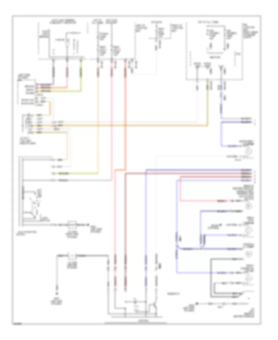 https://portal-diagnostov.com/license.html
Automotive Electricians Portal FZCO
Automotive Electricians Portal FZCO
https://portal-diagnostov.com/license.html
https://portal-diagnostov.com/license.html
Automotive Electricians Portal FZCO
Automotive Electricians Portal FZCOList of elements for Instrument Illumination Wiring Diagram (1 of 3) for Hyundai Equus Ultimate 2012:
- (left side of dash) ipm
- (rear of center console) console vent temperature
- Actuator & switch
- Auto
- Auto light sensor
- Auto light sensor & security indicator
- B-can high
- B-can low
- Body unit fuse 10a
- Body unit-1 fuse 10a
- Body unit-2 fuse 10a
- Console lamp
- Control
- E/r junction box (right rear of engine compt)
- E/r-e1b
- E/r-e2a
- Em21
- Em41
- Fam
- Fam power-1 fuse 40a
- Fam power-2 fuse 40a
- Fam-a
- Fam-b
- Fam-c
- Front cigarette lighter
- Gm01 (left end of dash)
- Gm06 (left end of dash)
- Ground
- Hot at all times
- Hot in on
- Hot in on or start
- I/p-lha
- I/p-lhc
- I/p-lhf
- I/p-lhg
- I/p-rhd
- Ill
- Ill(+)
- Instrument cluster
- J/c jm03 (right end of dash)
- J/c jm05 (center of dash)
- J/c jm11 (top left side of dash)
- J/c jm21 (rear of center console)
- Left i/p junction box
- Light
- M/f sw ecu
- M11-a
- M40-a
- M40-c
- Media jack module
- Mem pwr
- Mm02
- Mm11
- Multi-function
- Nca
- Off
- P/conn fuse 30a
- Power
- Rheostat
- Right i/p junction box
- Signal
- Sound systems
- Switch
Instrument Illumination Wiring Diagram (2 of 3) for Hyundai Equus Ultimate 2012
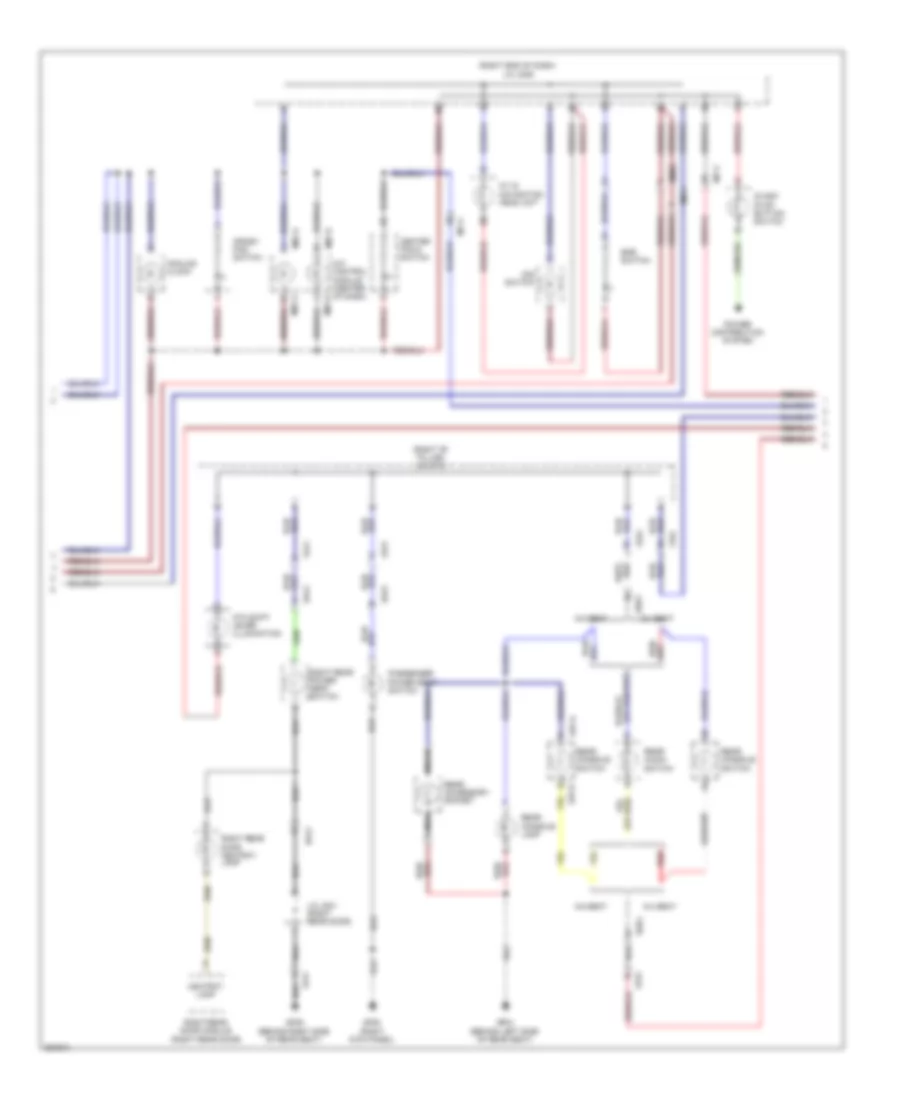 https://portal-diagnostov.com/license.html
Automotive Electricians Portal FZCO
Automotive Electricians Portal FZCO
https://portal-diagnostov.com/license.html
https://portal-diagnostov.com/license.html
Automotive Electricians Portal FZCO
Automotive Electricians Portal FZCOList of elements for Instrument Illumination Wiring Diagram (2 of 3) for Hyundai Equus Ultimate 2012:
- (right "b" pillar) j/c jf13
- (right end of dash) j/c jm06
- 5:5 seat
- 6:4 seat
- A/c control module (center of dash)
- A/v & navigation head unit
- Analog clock
- Ashtray lamp
- Atm shift lever illumination
- Center facia switch
- Crash pad switch
- Dd21
- Dd41
- Dis switch
- Epb switch
- Fd21
- Fd41
- Ff01
- Fs31
- Gf04 (behind left side of rear seat)
- Gf05 (right kick panel)
- Gf09 (behind right side of rear seat)
- J/c jd41 (right rear door)
- M07-a
- M07-d
- Mf11
- Mm02
- Mm11
- Nca
- Passenger power seat switch
- Power distribution system
- Rear accessory socket
- Rear audio switch
- Rear console lamp
- Rear console switch
- Red
- Right rear door ashtray lamp
- Right rear door module (right rear door)
- Right rear power seat switch
- S37-a
- S37-b
- Ss51
- Start stop button switch
Instrument Illumination Wiring Diagram (3 of 3) for Hyundai Equus Ultimate 2012
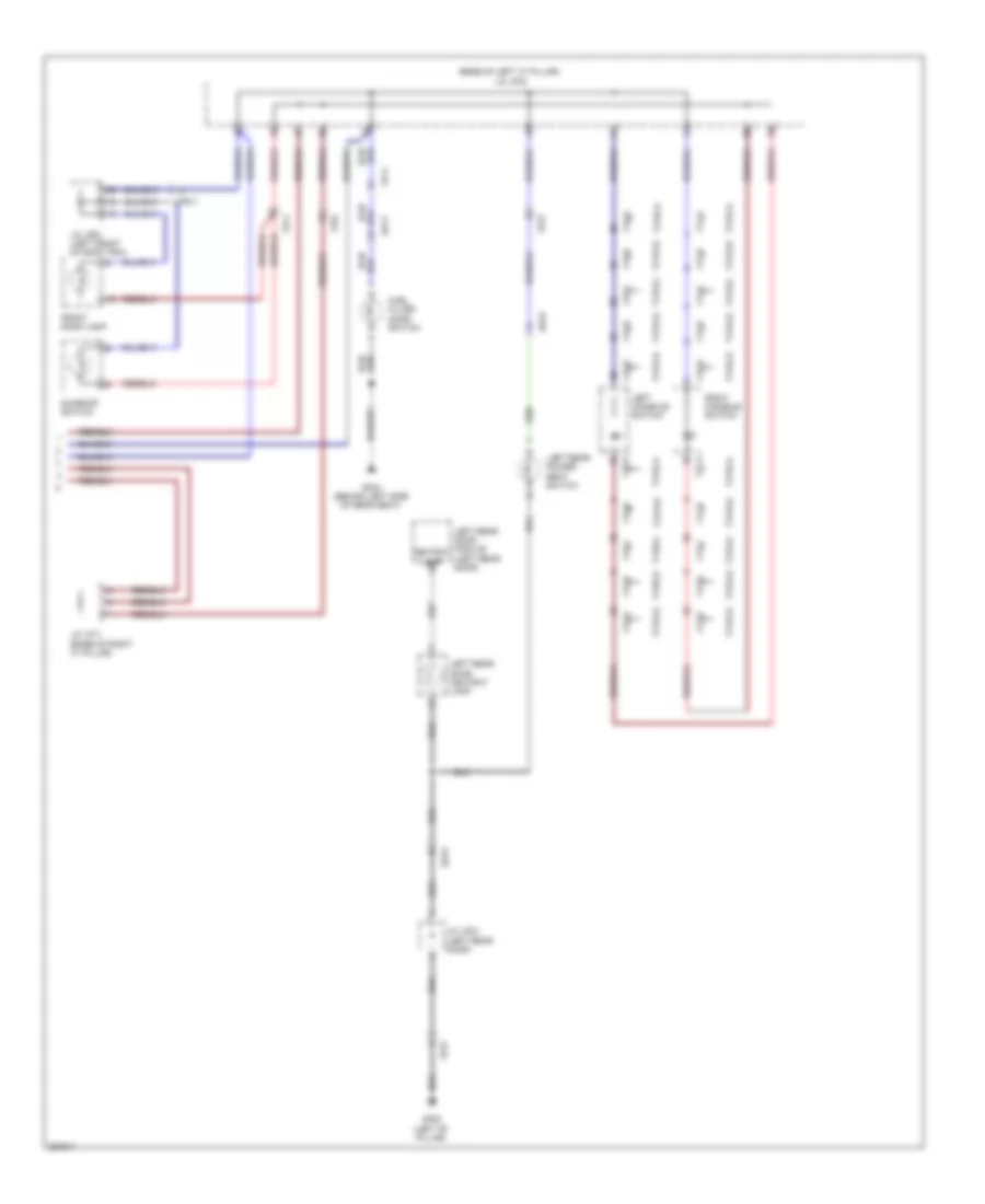 https://portal-diagnostov.com/license.html
Automotive Electricians Portal FZCO
Automotive Electricians Portal FZCO
https://portal-diagnostov.com/license.html
https://portal-diagnostov.com/license.html
Automotive Electricians Portal FZCO
Automotive Electricians Portal FZCOList of elements for Instrument Illumination Wiring Diagram (3 of 3) for Hyundai Equus Ultimate 2012:
- (base of left "c" pillar) j/c jf02
- Ashtray lamp
- Dd11
- Dd31
- F15-a
- F15-b
- F15-c
- F15-d
- F15-e
- F17-a
- F17-b
- F17-c
- F17-d
- F17-e
- Fd11
- Fd31
- Ff01
- Fr11
- Front room lamp
- Fuel filler door switch
- Gf02 (left "b" pillar)
- Gf04 (behind left side of rear seat)
- J/c jd31 (left rear door)
- J/c jf11 (base of right "c" pillar)
- J/c jr01 (left front of roof trim)
- Left console switch
- Left rear door ashtray lamp
- Left rear door module (left rear door)
- Left rear power seat switch
- Right console switch
- Sunroof switch
- Type-a
- Type-b
- Type-c
- Type-d
- Type-e
MEMORY SYSTEMS
Driver"s Memory Seat Wiring Diagram (1 of 2) for Hyundai Equus Ultimate 2012
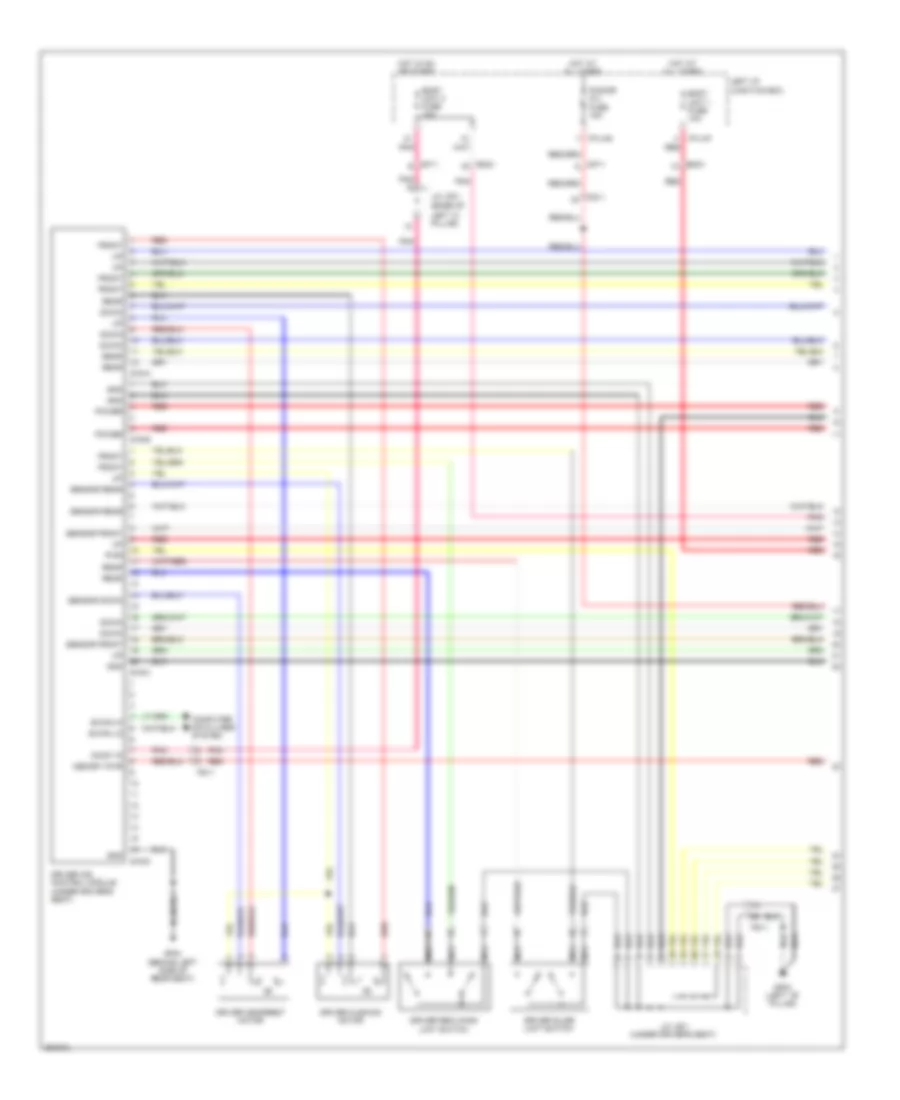 https://portal-diagnostov.com/license.html
Automotive Electricians Portal FZCO
Automotive Electricians Portal FZCO
https://portal-diagnostov.com/license.html
https://portal-diagnostov.com/license.html
Automotive Electricians Portal FZCO
Automotive Electricians Portal FZCOList of elements for Driver"s Memory Seat Wiring Diagram (1 of 2) for Hyundai Equus Ultimate 2012:
- B-can hi
- B-can lo
- Body unit 1 fuse 10a
- Body unit 2 fuse 10a
- Computer data lines system
- Down
- Driver cushion motor
- Driver headrest motor
- Driver ims control module (under driver's seat)
- Driver reclining limit switch
- Driver slide limit switch
- Em21
- Fd11
- Front
- Fs11
- Gf02 (left ``b" pillar)
- Gf04 (behind left side of rear seat)
- Gnd
- Hot at all times
- Hot in on or start
- I/p-lhf
- I/p-lhg
- J/c jf01 (base of
- J/c js11 (under driver's seat)
- Left "c" pillar)
- Left i/p junction box
- Memory pwr
- Mf11
- Nca
- On/st in
- P/door (fl) fuse 15a
- Pnk
- Power
- Pwr
- Rear
- Red
- S16-a
- S16-b
- S16-c
- S16-d
- Sensor down
- Sensor front
- Sensor rear
Driver"s Memory Seat Wiring Diagram (2 of 2) for Hyundai Equus Ultimate 2012
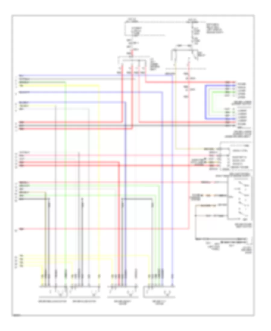 https://portal-diagnostov.com/license.html
Automotive Electricians Portal FZCO
Automotive Electricians Portal FZCO
https://portal-diagnostov.com/license.html
https://portal-diagnostov.com/license.html
Automotive Electricians Portal FZCO
Automotive Electricians Portal FZCOList of elements for Driver"s Memory Seat Wiring Diagram (2 of 2) for Hyundai Equus Ultimate 2012:
- (left kick panel)
- (right rear of engine compt)
- (under driver's seat)
- Alt fuse 200a
- B-can hi
- B-can low
- Computer data lines system
- Cpu
- Dd11
- Driver height motor
- Driver lumbar support switch
- Driver lumbar support valve
- Driver power seat switch
- Driver reclining motor
- Driver slide motor
- Driver tilt motor
- E/r fuse & relay box (left side of engine compt)
- E/r junction box
- E/r-e1a
- E/r-e1b
- Ef11
- Em31
- Fam
- Fam-b
- Fd11
- Fs11
- Gf01
- Gnd
- Hot at all times
- Ims fuse 10a
- Ims relay
- Ims rly ctrl
- J/c jd11 (driver's door)
- J/c js11 (under driver's seat)
- Led gnd
- Lower
- Lumbar
- Memory power
- Mf21
- Middle
- On/start in
- P/seat (fr-lh) fuse 30a
- Pnk
- Power
- Power windows system
- Red
- Serial
- Set
- Upper
Memory Power Tilt & Power Telescopic Wiring Diagram for Hyundai Equus Ultimate 2012
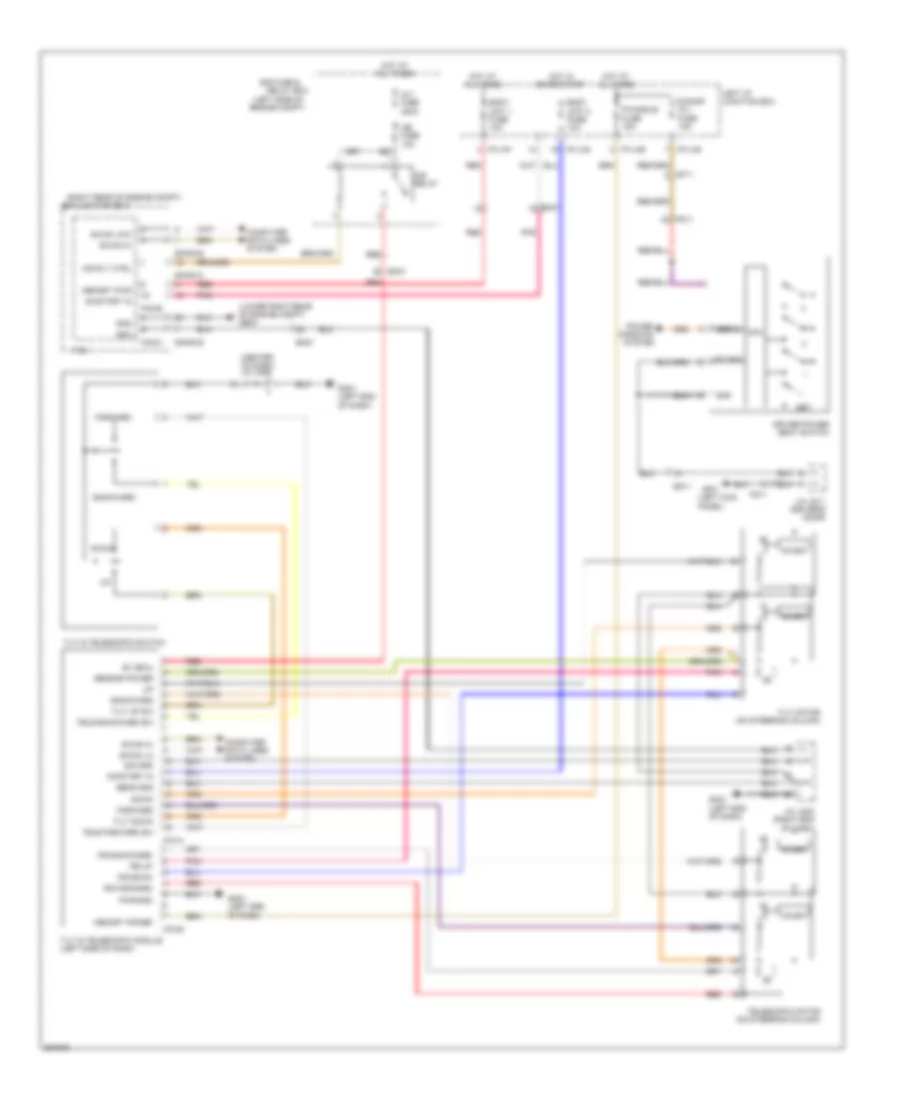 https://portal-diagnostov.com/license.html
Automotive Electricians Portal FZCO
Automotive Electricians Portal FZCO
https://portal-diagnostov.com/license.html
https://portal-diagnostov.com/license.html
Automotive Electricians Portal FZCO
Automotive Electricians Portal FZCOList of elements for Memory Power Tilt & Power Telescopic Wiring Diagram for Hyundai Equus Ultimate 2012:
- (center of dash) j/c jm05
- (left kick panel)
- (left side of
- (lower right rear of engine compt) ge04
- (right rear of engine compt)
- Alt fuse 200a
- B+ (ecu)
- B-can hi
- B-can lo
- B-can low
- Backward
- Body unit 1 fuse 10a
- Body unit 2 fuse 10a
- Computer data lines system
- Cpu
- Dd11
- Down
- Driver power seat switch
- E/r fuse &
- E/r junction box
- E/r-e1a
- E/r-e1b
- Em21
- Em31
- Engine compt)
- Fam
- Fam-b
- Fam-c
- Fd11
- Forward
- Gf01
- Gm01 (left end of dash)
- Gnd
- Holeic
- Hot at all times
- Hot in on or start
- I/p-lhe
- I/p-lhf
- I/p-lhg
- Ims fuse 10a
- Ims relay
- Ims rly ctrl
- Ips backward
- Ips down
- Ips forward
- Ips up
- J/c jd11 (driver's door)
- J/c jm03 (right end of dash)
- Led gnd
- Left i/p junction box
- M70-a
- M70-b
- Memory power
- Memory pwr
- Mf11
- On/start in
- P/door (fl) fuse 15a
- P/handle fuse 15a
- Pnk
- Power windows system
- Pwr gnd
- Red
- Relay box
- Sens gnd
- Sensor power
- Serial
- Set
- Sig gnd
- Tele backward sw
- Tele forward sw
- Telescopic motor (on steering column)
- Tilt & telescopic module (left side of dash)
- Tilt & telescopic switch
- Tilt down
- Tilt motor (on steering column)
- Tilt up sw
NAVIGATION
Driver Information System Wiring Diagram (1 of 4) for Hyundai Equus Ultimate 2012
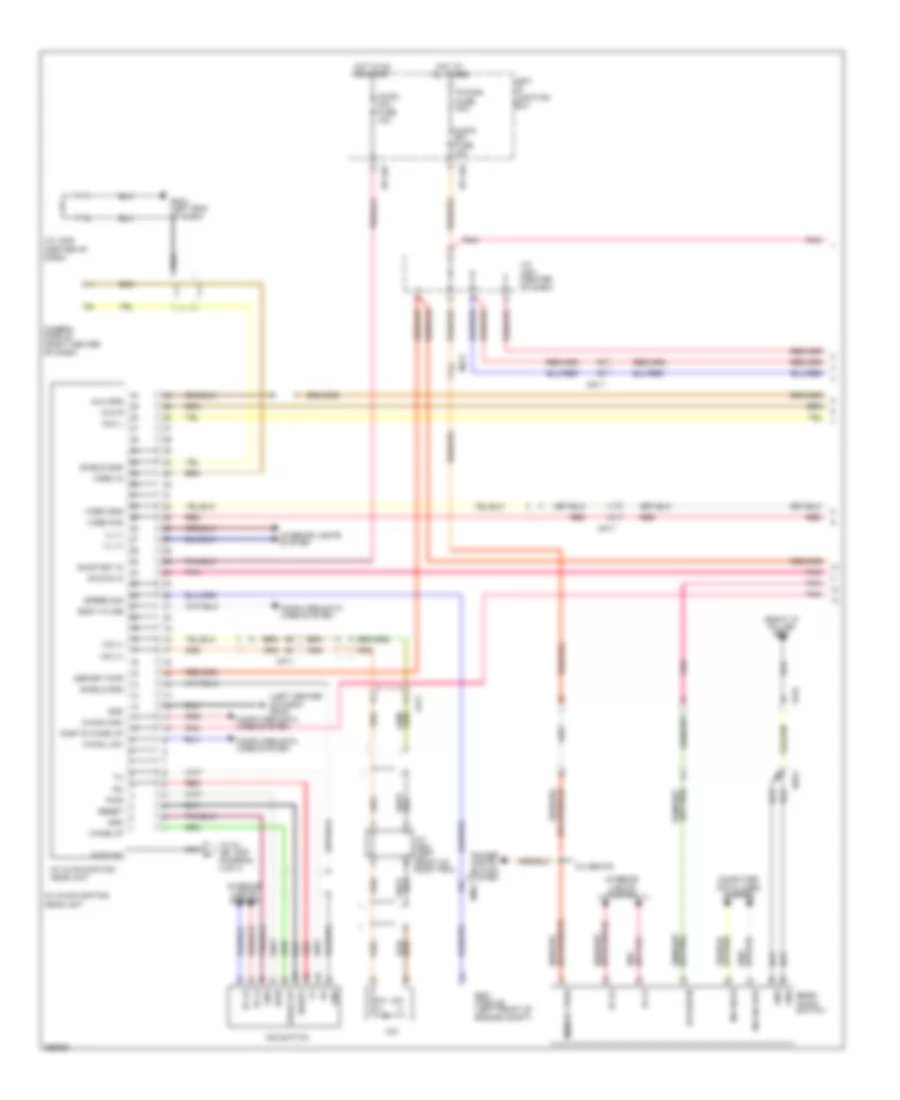 https://portal-diagnostov.com/license.html
Automotive Electricians Portal FZCO
Automotive Electricians Portal FZCO
https://portal-diagnostov.com/license.html
https://portal-diagnostov.com/license.html
Automotive Electricians Portal FZCO
Automotive Electricians Portal FZCOList of elements for Driver Information System Wiring Diagram (1 of 4) for Hyundai Equus Ultimate 2012:
- (center of dash)
- (left center of dash) gmo3
- (right "c" pillar) gf07
- 6:4 seats
- A/v & navigation head unit
- Acc/on in
- Audio (b+) fuse 15a
- Audio (ig1) fuse 10a
- Aux gnd
- Aux l
- Aux r
- Body k-line
- Camera module (right center of dash)
- Computer data lines system
- Dis switch
- Em41
- Esc module (left front of engine compt)
- Fr11
- Fs31
- Gmo1 (left end of dash)
- Gnd
- Hot at all times
- Hot in on or start
- I/p-lhc
- I/p-lhg
- Ill (+)
- Ill (-)
- Interior lights system
- J/c jm01 (center of dash)
- J/c jm05
- J/c jr03 (left front of room trim)
- Left i/p junction box
- M-can hi
- M-can high
- M-can low
- Memory pwr
- Mf11
- Mf21
- Mic
- Mic (+)
- Mic (-)
- Mm11
- Most e wake up
- Most rx
- Nca
- On/start in
- P/conn fuse 30a
- Pnk
- Power distri- bution system
- Pwr
- Rear audio switch
- Red
- Reset
- Shield gnd
- Speed sig
- Ss51
- To av jbl amp (diagram 4 of 4)
- Video gnd
- Video in
- Video sig
- Wake up
Driver Information System Wiring Diagram (2 of 4) for Hyundai Equus Ultimate 2012
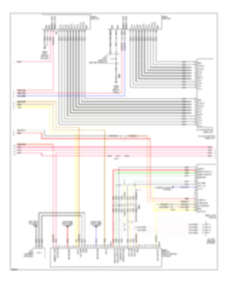 https://portal-diagnostov.com/license.html
Automotive Electricians Portal FZCO
Automotive Electricians Portal FZCO
https://portal-diagnostov.com/license.html
https://portal-diagnostov.com/license.html
Automotive Electricians Portal FZCO
Automotive Electricians Portal FZCOList of elements for Driver Information System Wiring Diagram (2 of 4) for Hyundai Equus Ultimate 2012:
- (left end of dash) gm01
- A/v & navigation head unit
- Acc/on in
- Aux detect
- Aux gnd
- Aux l
- Aux l in
- Aux r
- Aux r in
- Aux ref
- Computer data lines system
- Dash)
- Data
- Front monitor
- Gmo3 (left center
- Gmo6 (left end of
- Gnd
- Ill (+)
- Interior lights system
- J/c jm01 (center of dash)
- J/c jm05 (center of dash)
- J/c jm21 (rear of center console)
- M-can high
- M-can low
- M31
- M45-a
- M45-b
- Media jack module
- Media module (right center of dash)
- Memory pwr
- Mf11
- Mm11
- Nca
- Of dash)
- Pnk
- Rear monitor
- Red
- Tx0+
- Tx0-
- Tx1+
- Tx1-
- Tx2+
- Tx2-
- Txclk+
- Txclk-
- Usb 5v
- Usb d+/ipod tx
- Usb d-/ipod rx
- Usb gnd
- Usb/ipod 5v
- Usb/ipod gnd
- Video gnd
- Video in
Driver Information System Wiring Diagram (3 of 4) for Hyundai Equus Ultimate 2012
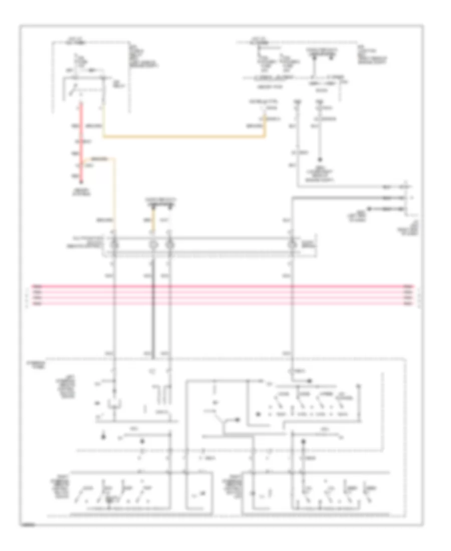 https://portal-diagnostov.com/license.html
Automotive Electricians Portal FZCO
Automotive Electricians Portal FZCO
https://portal-diagnostov.com/license.html
https://portal-diagnostov.com/license.html
Automotive Electricians Portal FZCO
Automotive Electricians Portal FZCOList of elements for Driver Information System Wiring Diagram (3 of 4) for Hyundai Equus Ultimate 2012:
- (if equip- ped)
- 12v
- B-can
- Can ic
- Clock spring
- Computer data lines system
- Disp
- E/r fuse & relay box (left side of engine compt)
- E/r junction box (right rear of engine compt)
- E/r-e1a
- E/r-e1b
- Em21
- Em31
- Engine compt)
- Fam
- Fam power-1 fuse 40a
- Fam power-2 fuse 40a
- Fam-a
- Fam-b
- Fam-c
- Ge04 (lower right rear of
- Gm01 (left end of dash)
- Gnd
- H/f cancel
- H/free
- High
- Hot at all times
- Ill
- Ims fuse 10a
- Ims relay
- Ims relay ctrl
- J/c jm03 (right end of dash)
- Ldws
- Left steering remote control switch (down)
- Low
- M92-a
- M92-b
- Mcu
- Memory pwr
- Memory systems
- Mf21
- Mode
- Multifunction switch (remote control)
- Nca
- Pnk
- Red
- Right steering remote control switch (down)
- Right steering remote control switch (up)
- Scc
- Seek (+)
- Seek (-)
- Steering wheel
- Trip
- Voice
- Vol (+)
- Vol (-)
Driver Information System Wiring Diagram (4 of 4) for Hyundai Equus Ultimate 2012
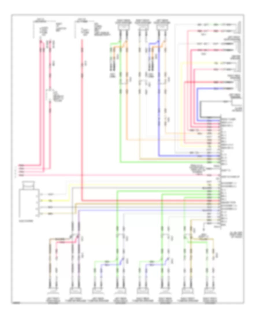 https://portal-diagnostov.com/license.html
Automotive Electricians Portal FZCO
Automotive Electricians Portal FZCO
https://portal-diagnostov.com/license.html
https://portal-diagnostov.com/license.html
Automotive Electricians Portal FZCO
Automotive Electricians Portal FZCOList of elements for Driver Information System Wiring Diagram (4 of 4) for Hyundai Equus Ultimate 2012:
- (+)
- (-)
- (not used)
- Amp 1 fuse 40a
- Audio (acc) fuse 10a
- Av jbl amp (right side of trunk)
- Center speaker
- Dd11
- Dd21
- Dd31
- Dd41
- Deck lh (+)
- Deck lh (-)
- Deck rh (+)
- Deck rh (-)
- E/r fuse & relay box (left side of engine compt)
- Ef11
- F07
- F08-a
- F08-b
- Fd11
- Fd21
- Fd31
- Fd41
- Ff01
- Fl (+)
- Fl (-)
- Fr (+)
- Fr (-)
- From a/v & navigation head unit a (diagram 1 of 4)
- Gf07 (right "c" pillar)
- Glass antenna
- Gnd
- Hot at all times
- Hot in acc or on
- I/p-rhd
- I/p-rhe
- J/c jf11 (base of right "c" pillar)
- Left deck speaker
- Left front door middle speaker
- Left front door speaker
- Left front tweeter speaker
- Left rear door middle speaker
- Left rear door speaker
- Left rear tweeter speaker
- Memory pwr
- Mf21
- Most e wake up
- Most tx
- Nca
- Pnk
- Radio tuner
- Red
- Right deck speaker
- Right front door middle speaker
- Right front door speaker
- Right front tweeter speaker
- Right i/p junction box
- Right rear door middle speaker
- Right rear door speaker
- Right rear tweeter speaker
- Rl (+)
- Rl (-)
- Rr (+)
- Rr (-)
- S/woofer 1 (+)
- S/woofer 1 (-)
- S/woofer 2 (+)
- S/woofer 2 (-)
- Sub woofer
Front & Rear Camera Wiring Diagram for Hyundai Equus Ultimate 2012
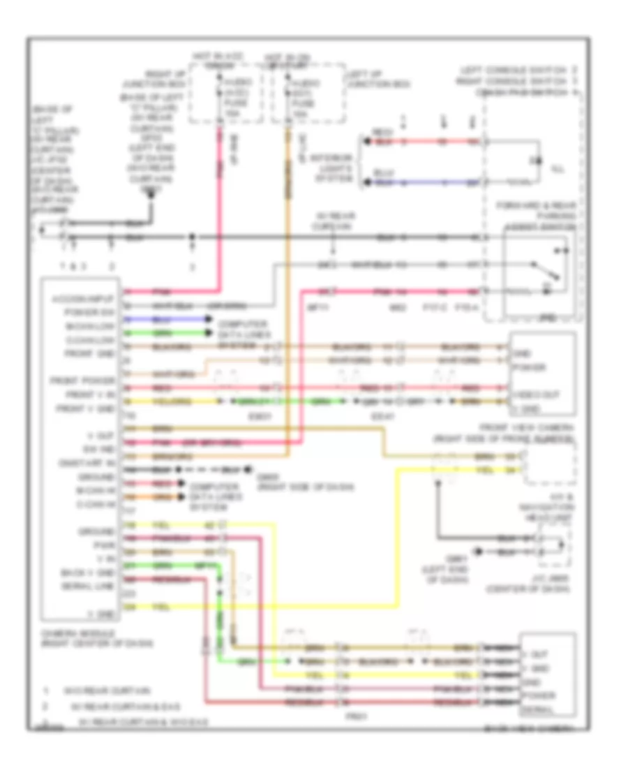 https://portal-diagnostov.com/license.html
Automotive Electricians Portal FZCO
Automotive Electricians Portal FZCO
https://portal-diagnostov.com/license.html
https://portal-diagnostov.com/license.html
Automotive Electricians Portal FZCO
Automotive Electricians Portal FZCOList of elements for Front & Rear Camera Wiring Diagram for Hyundai Equus Ultimate 2012:
- (base of
- (base of left "c" pillar) (w/ rear
- (center of dash) (w/o rear curtain) j/c jm05
- (right side of front bumper)
- A/v & navigation head unit
- Acc/on input
- Audio (acc)
- Audio (ig1)
- Back v gnd
- Back view camera
- C-can hi
- C-can low
- Camera module (right center of dash)
- Computer data lines system
- Crash pad switch
- Curtain) gf03 (left end of dash) (w/o rear
- Curtain) gm01
- Ee41
- Em31
- F15-a
- F17-c
- Forward & rear parking assist switch
- Fr01
- Front gnd
- Front power
- Front v gnd
- Front v in
- Front view camera
- Fuse 10a
- Gm01 (left end of dash)
- Gm05 (right side of dash)
- Gnd
- Ground
- Hot in acc or on
- Hot in on or start
- I/p-lhc
- I/p-rhe
- Ill
- Ind
- Interior lights system
- J/c jm05 (center of dash)
- Left "c" pillar) (w/ rear curtain) j/c jf02
- Left console switch
- Left i/p junction box
- M-can hi
- M-can low
- M62
- Mf11
- Nca gnd
- Nca power
- Nca serial
- Nca v gnd
- Nca v out
- On/start in
- Pnk
- Power
- Power sw
- Pwr
- Red
- Right console switch
- Right i/p junction box
- Serial line
- Sw ind
- V gnd
- V in
- V out
- Video out
- W/ rear curtain
- W/ rear curtain & eas
- W/ rear curtain & w/o eas
- W/o rear curtain
Parking Assistant Wiring Diagram for Hyundai Equus Ultimate 2012
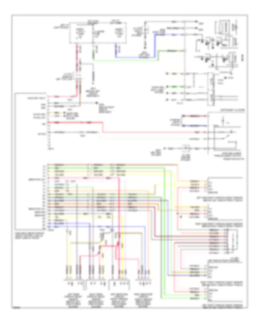 https://portal-diagnostov.com/license.html
Automotive Electricians Portal FZCO
Automotive Electricians Portal FZCO
https://portal-diagnostov.com/license.html
https://portal-diagnostov.com/license.html
Automotive Electricians Portal FZCO
Automotive Electricians Portal FZCOList of elements for Parking Assistant Wiring Diagram for Hyundai Equus Ultimate 2012:
- +8v
- 24v reg
- 3v reg
- 5v reg
- 9v reg
- B can high
- B can low
- Body unit 1 fuse 10a
- Body unit 2 fuse 10a
- Chip
- Cluster fuse 10a
- Computer data lines system
- Crash pad switch
- Driver tft lcd
- Ee41
- Ef41
- F36-a
- F36-b
- Ff01
- Forward & rear parking assist control module (right side of trunk)
- Forward & rear parking assist switch
- Fr31
- Gf04 (behind left side of rear seat)
- Gf09 (behind right side of rear seat)
- Gm01 (left end of dash)
- Gm05 (right side of dash)
- Gnd
- Ground
- Hot at all times
- Hot in on or start
- I/p-lhe
- I/p-lhf
- I/p-lhg
- Ill
- Ind
- Instrument cluster
- Interior lights system
- J/c je21 (left end of front bumper)
- J/c jf01 (base of left "c"pillar)
- J/c jm03 (right end of dash)
- J/c jm05 (center of dash)
- Left front parking assist sensor (behind left side of front fascia)
- Left i/p junction box
- Left rear parking assist sensor (behind left side of rear bumper)
- Left rear side parking assist sensor (behind left side of rear bumper)
- Left side front parking assist sensor (behind left side of front fascia)
- Low
- M11-a
- Mf11
- Mf21
- Micom
- On/start input
- Panel
- Pnk
- Red
- Right front parking assist sensor (behind right side of front fascia)
- Right rear parking assist sensor (behind right side of rear bumper)
- Right rear side parking assist sensor (behind right side of rear bumper)
- Right side front parking assist sensor (behind right side of front fascia)
- Rom
- Sens gnd
- Sens pwr (+8v)
- Sound
- Speaker
- Sw sig
- Tftlcd
- Transceiver b-can
- Transceiver c-can
POWER DISTRIBUTION
Power Distribution Wiring Diagram (1 of 10) for Hyundai Equus Ultimate 2012
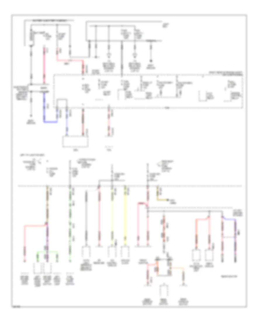 https://portal-diagnostov.com/license.html
Automotive Electricians Portal FZCO
Automotive Electricians Portal FZCO
https://portal-diagnostov.com/license.html
https://portal-diagnostov.com/license.html
Automotive Electricians Portal FZCO
Automotive Electricians Portal FZCOList of elements for Power Distribution Wiring Diagram (1 of 10) for Hyundai Equus Ultimate 2012:
- (center of dash)
- (not used)
- (right rear of engine compt) e/r junction box
- 5:5 seat
- 6:4 seat
- A/c control module
- A/con (b+) fuse 10a
- A/v & navigation head unit
- Analog clock
- Audio (b+) fuse 15a
- Auto light sensor & security indicator
- Battery
- Battery & battery fuse box
- Body ground
- Bs fuse 10a
- Ctg-k
- Ctg-zf
- Dd11
- Driver power door latch
- Driver power seat switch
- E/r batt 1 fuse 125a
- E/r batt 2 fuse 125a
- E/r-ca
- E/r-cb
- E/r-e1a
- E/r-e2a
- Ecm
- Ecu (b+) fuse 10a
- Ecu fuse 30a
- Ee01
- Ef01
- Ef21
- Engine control relay
- F/lid open fuse 10a
- Fam
- Fam power-1
- Fam power-2 fuse 40a
- Fam-a
- Fam-c
- Fd11
- Ff11
- From body unit-1 fuse (diagram 3 of 10)
- From p/conn fuse (diagram 3 of 10)
- Front monitor
- Fs31
- Fuel filler door switch
- Fuel pump fuse 20a
- Fuel pump relay
- Fuse 30a
- Fuse 40a
- H/lp (low) relay
- I/p-lha
- I/p-lhc
- I/p-lhd
- I/p-lhg
- J/c jm01
- Joint box
- Left front door lamp
- Left front door mood lamp
- Left i/p junction box
- Lin line
- M07-a
- M45-a
- Media module
- Mf11
- Mf21
- Mm11
- Nca
- P/door (fl) fuse 15a
- Pnk
- Rear audio switch
- Rear console switch
- Rear monitor
- Red
- Red/
- Rf receiver
- Room lamp relay
- Room lp fuse 10a
- S37-a
- Snsr+
- Ss51
- Start
- Start fuse 50a
- Start motor
- Start relay
- Tcm
- Terminal
- To e/r fuse & relay box (diagram 2 of 10)
- To e/r fuse & relay box (diagram 3 of 10)
- To p/door (rl) fuse (diagram 4 of 10)
Power Distribution Wiring Diagram (2 of 10) for Hyundai Equus Ultimate 2012
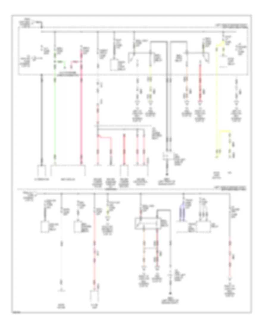 https://portal-diagnostov.com/license.html
Automotive Electricians Portal FZCO
Automotive Electricians Portal FZCO
https://portal-diagnostov.com/license.html
https://portal-diagnostov.com/license.html
Automotive Electricians Portal FZCO
Automotive Electricians Portal FZCOList of elements for Power Distribution Wiring Diagram (2 of 10) for Hyundai Equus Ultimate 2012:
- (diagram 2 of 10)
- (left side of engine compt) e/r fuse & relay box
- Alt fuse 200a
- Alternator
- Amp-1 fuse 40a
- Av jbl amp
- B/up lp-1 fuse 10a
- Back- up lamp relay
- Cooling fan fuse 60a
- Cooling fan relay
- Driver ims control switch
- Driver lumbar support switch
- Driver lumbar support valve
- Driver massage module (w/ message)
- Ef11
- Ehps fuse 80a
- Ehps motor
- Em11
- Em21
- Em31
- Em41
- Esc compre- ssor relay
- Esc fuse 40a
- Esc module
- Escl (acc) fuse 30a
- Escl (acc) relay
- Escl (ign1) fuse 30a
- Escl (ign1) relay
- Escl (ign2) fuse 30a
- Escl (ign2) relay
- Esp-1 fuse 30a
- Esp-2 fuse 30a
- F08-a
- From alt fuse c
- From joint box a (diagram 1 of 10)
- Fs11
- Fuse 60a
- Ge03 (left front of engine compt)
- I/p power (lh)
- I/p power (rh)
- Ims fuse 10a
- Ims relay
- Ipm
- J/c je02 (top left side of dash)
- J/c js11 (under driver's seat)
- M40-c
- Multipurpose check connector
- Nca
- P/outlet (fr) fuse 25a
- P/seat (fr-lh) fuse 30a
- Pnk
- Red
- S16-b
- Stop lamp relay
- Stop lamp switch
- Stop lp fuse 10a
- To cooling fuse (diagram 2 of 10)
- To left i/p junction box (diagram 3 of 10)
- To left i/p junction box (diagram 5 of 10)
- To p/outlet (fr) relay (diagram 8 of 10)
- To pdm (diagram 10 of 10)
- To right i/p junction box (diagram 6 of 10)
- To right i/p junction box (diagram 8 of 10)
- Trunk lid open relay
- Trunk open fuse 10a
Power Distribution Wiring Diagram (3 of 10) for Hyundai Equus Ultimate 2012
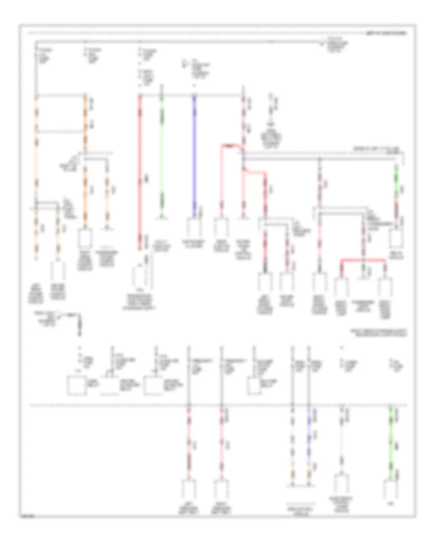 https://portal-diagnostov.com/license.html
Automotive Electricians Portal FZCO
Automotive Electricians Portal FZCO
https://portal-diagnostov.com/license.html
https://portal-diagnostov.com/license.html
Automotive Electricians Portal FZCO
Automotive Electricians Portal FZCOList of elements for Power Distribution Wiring Diagram (3 of 10) for Hyundai Equus Ultimate 2012:
- (base of left "c" pillar)
- (diagram 1 of 10)
- (right rear of engine compt) engine room junction box
- Blower motor fuse 40a
- Blower relay
- Body unit-1 fuse 10a
- D51-c
- D61-c
- Dd11
- Dd21
- Door)
- Driver door module
- Driver power window module
- E/r-e1b
- E/r-e2b
- Ef11
- Ef21
- Ef31
- Electronic control wiper module
- Em21
- Engine room junction box (right rear of engine compt)
- Epb control module
- Epb-1 fuse 15a
- Epb-2 fuse 15a
- Fam
- Fam-b
- Fd11
- Fd21
- Fd31
- Fd41
- Ff02
- From e/r fuse & relay box (diagram 2 of 10)
- From joint box b
- Fs51
- Heated glass (fr) relay
- Heated glass (rr) relay
- Horn fuse 15a
- Horn relay
- Htd glass (fr) fuse 15a
- Htd glass (rr) fuse 40a
- I/p-lhb
- I/p-lhd
- I/p-lhf
- Instrument cluster
- Ipm
- Ipm fuse 10a
- J/c jd11 (driver's door)
- J/c jd21 (front
- J/c jf01
- J/c jf03 (left kick panel)
- J/c jf13 (right "b" pillar)
- Left front smart outside handle
- Left i/p junction box
- Left pre-safe seat belt
- Left rear power window module
- M11-a
- M40-a
- Mf11
- Multi- function switch
- Nca
- P/conn fuse 30a
- P/wdw (lh) fuse 30a
- P/wdw (rh) fuse 30a
- Passenger door module
- Passenger power window module
- Passenger's
- Power trunk lid control module
- Presafety (lh) fuse 40a
- Presafety (rh) fuse 40a
- Rear curtain module
- Red
- Relax module
- Right front door lamp
- Right front door mood lamp
- Right front smart outside handle
- Right pre-safe seat belt
- Right rear power window module
- S70-d
- To audio (b+) fuse (diagram 1 of 10)
- To f/lid open fuse (diagram 1 of 10)
- Wiper fuse 30a
Power Distribution Wiring Diagram (4 of 10) for Hyundai Equus Ultimate 2012
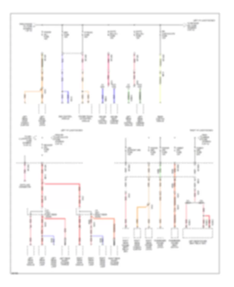 https://portal-diagnostov.com/license.html
Automotive Electricians Portal FZCO
Automotive Electricians Portal FZCO
https://portal-diagnostov.com/license.html
https://portal-diagnostov.com/license.html
Automotive Electricians Portal FZCO
Automotive Electricians Portal FZCOList of elements for Power Distribution Wiring Diagram (4 of 10) for Hyundai Equus Ultimate 2012:
- (diagram 1 of 10)
- 5:5 seat
- 6:4 seat
- Data link connector
- Dd21
- Dd31
- Dd41
- Driver ccs control module
- Driver seat warmer module
- Esc
- Esc control module
- F01-a
- Fd21
- Fd31
- Fd41
- From mirror fuse (diagram 8 of 10)
- From p/door (fl) fuse h
- From rr curtain mtr fuse (diagram 4 of 10)
- Fs11
- Fs31
- Fs41
- Fuse 10a
- Fuse 15a
- Fuse 30a
- H/rest (fr) fuse 10a
- I/p-lha
- I/p-lhc
- I/p-lhd
- I/p-lhe
- I/p-lhf
- I/p-lhg
- I/p-rha
- I/p-rhd
- I/p-rhe
- J/c jd31 (left rear door)
- J/c jd41 (right rear door)
- Left i/p junction box
- Left rear ccs control module
- Left rear door lamp
- Left rear door module
- Left rear door mood lamp
- Left rear door window curtain
- Left rear power door latch
- Left rear power seat relay box
- Left rear seat warmer module
- Left rear smart outside handle
- Leg support (rr) fuse 15a
- Mf11
- Mf21
- Nca
- P/door (fr) fuse 15a
- P/door (rl) fuse 15a
- P/door (rr) fuse 15a
- P/seat (rr) fuse 20a
- P/trunk
- Passenger power door latch
- Passenger power seat switch
- Pnk
- Power trunk lid control module
- Rear curtain module
- Red
- Red/
- Right i/p junction box
- Right rear door lamp
- Right rear door module
- Right rear door mood lamp
- Right rear door window curtain
- Right rear power door latch
- Right rear power seat relay box
- Right rear smart outside handle
- Rr curtain mtr
- Rr door mdl fuse 10a
- S/htd ecu (fl)
- S/htd ecu (rl)
- S06-a
- S106-a
- S126-1
- S126-2
- To key illumination fuse (diagram 10 of 10)
- To rr door mdl fuse (diagram 4 of 10)
- W/ ccs
- W/o ccs
Power Distribution Wiring Diagram (5 of 10) for Hyundai Equus Ultimate 2012
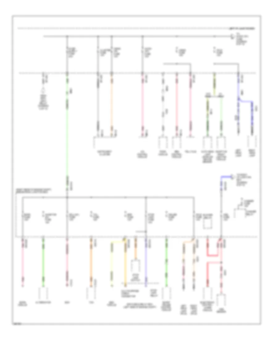 https://portal-diagnostov.com/license.html
Automotive Electricians Portal FZCO
Automotive Electricians Portal FZCO
https://portal-diagnostov.com/license.html
https://portal-diagnostov.com/license.html
Automotive Electricians Portal FZCO
Automotive Electricians Portal FZCOList of elements for Power Distribution Wiring Diagram (5 of 10) for Hyundai Equus Ultimate 2012:
- (right rear of engine compt) engine room junction box
- A/bag fuse 15a
- A/bag ind fuse 10a
- A/c control module
- A/con (ig1) fuse 10a
- Adaptive front lighting module
- Afls
- Afls fuse 10a
- Alternator
- Aqs fuse 10a
- Aqs sensor
- Auto head lamp leveling device sensor
- Blower relay
- Cluster fuse 10a
- Cruise fuse 10a
- Ctg-k
- Ctg-zf
- E/r fuse & relay box (left side of engine compt)
- E/r-cb
- E/r-e1a
- E/r-e1b
- E/r-e2a
- E/r-e2b
- Ecm
- Ecu (ig1) fuse 10a
- Ee21
- Ehps fuse 15a
- Ehps module
- Electronic control wiper module
- Em21
- Em41
- Esc module
- Esp fuse 10a
- Ff03
- From escl (ign1) relay (diagram 2 of 10)
- I/p-lha
- I/p-lhe
- I/p-lhg
- I/p-lhh
- Inhibitor sw fuse 15a
- Instrument cluster
- Left head lamp
- Left head lamp (afls)
- Left i/p junction box
- M07-a
- M11-a
- M11-b
- M71-a
- Mf01
- Mf11
- Multipurpose check connector
- Nca
- Pnk
- Pods module
- Red
- Right head lamp
- Right head lamp (afls)
- Smart cruise control module
- Srs control module
- Stop lamp fuse 10a
- Stop lamp relay
- Stop lamp switch
- Tcm
- Tcu fuse 15a
- Telltale
- To audio (ig1) fuse (diagram 6 of 10)
- To right i/p junction box (diagram 6 of 10)
- W/o afls
- Washer fuse 15a
- Washer relay
Power Distribution Wiring Diagram (6 of 10) for Hyundai Equus Ultimate 2012
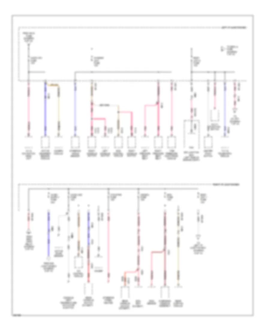 https://portal-diagnostov.com/license.html
Automotive Electricians Portal FZCO
Automotive Electricians Portal FZCO
https://portal-diagnostov.com/license.html
https://portal-diagnostov.com/license.html
Automotive Electricians Portal FZCO
Automotive Electricians Portal FZCOList of elements for Power Distribution Wiring Diagram (6 of 10) for Hyundai Equus Ultimate 2012:
- (5:5 seat)
- (6:4 seat)
- (diagram 9 of 10)
- A/c control module
- A/con (ig2) fuse 10a
- A/v & navigation head unit
- Active headrest sensor module
- Active incar sensor
- Audio (ig1) fuse 10a
- Body unit 1 fuse 10a
- Body unit-2 fuse 10a
- Camera module
- Center facia switch
- Chassis unit fuse 10a
- Console vent temperature actuator & switch
- Cool box
- E/r junction box (left side of engine compt)
- E/r-e1b
- Ecm fuse 10a
- Ecs control module
- Em21
- F01-a
- F15-c
- F15-e
- F17-a
- F17-c
- F17-e
- Fam
- Fam-b
- Fr21
- From afls fuse (diagram 5 of 10)
- From e/r junction box (diagram 5 of 10)
- From escl (ign2) relay (diagram 2 of 10)
- Fs41
- Htd strg fuse 15a
- I/p-lha
- I/p-lhc
- I/p-lhf
- I/p-lhg
- I/p-rha
- I/p-rhb
- I/p-rhd
- Ice box fuse 15a
- Ionizer
- Left console switch
- Left i/p junction box
- Left pre-safe seat belt
- M07-c
- M70-a
- Mf11
- Mf21
- Mm11
- Multi- function switch
- Overhead console assembly
- Pnk
- Rain sensor
- Rear console switch
- Rear curtain module
- Red
- Red/
- Right console switch
- Right i/p junction box
- Right pre-safe seat belt
- S37-a
- Ss41
- Steering angle sensor
- Steering wheel heated
- Tilt & telescopic module
- Tire pressure monitoring module
- To escl-2 fuse (diagram 7 of 10)
- To j/c jf01 (diagram 7 of 10)
- To left i/p junction box
Power Distribution Wiring Diagram (7 of 10) for Hyundai Equus Ultimate 2012
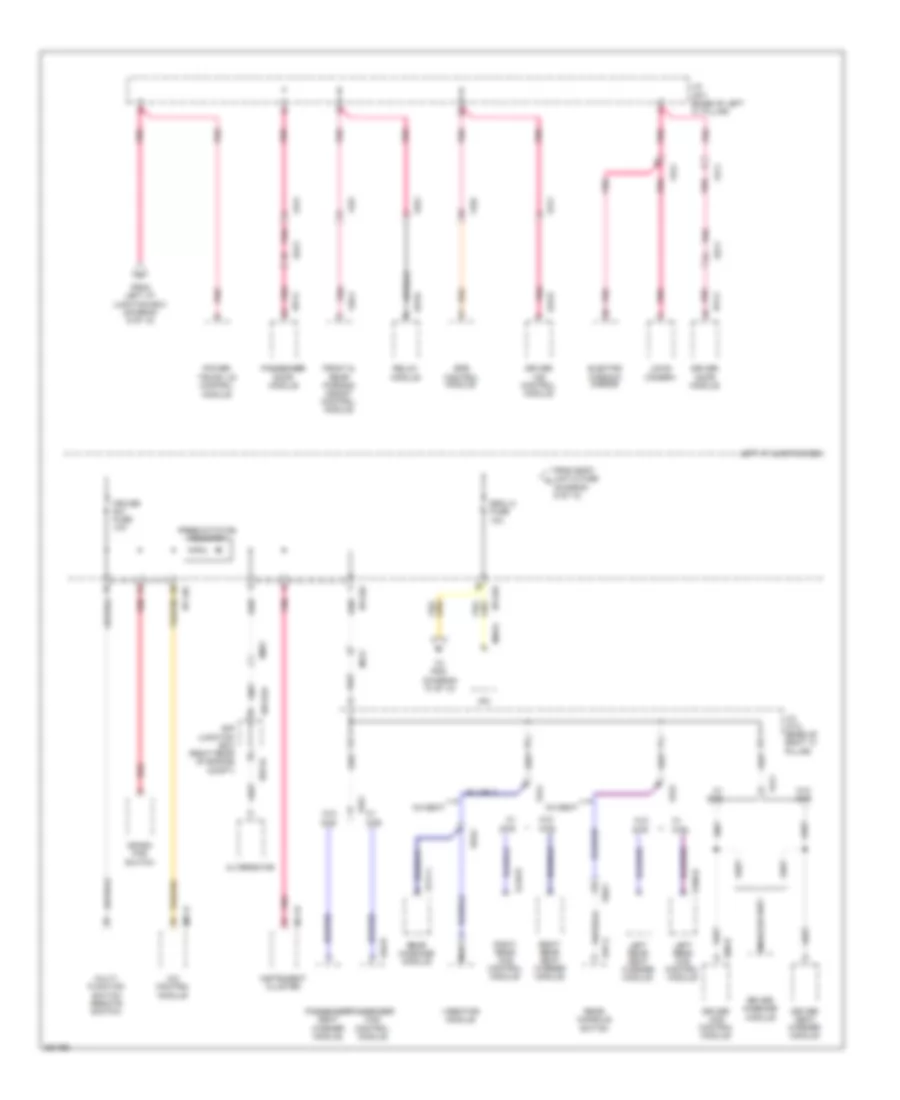 https://portal-diagnostov.com/license.html
Automotive Electricians Portal FZCO
Automotive Electricians Portal FZCO
https://portal-diagnostov.com/license.html
https://portal-diagnostov.com/license.html
Automotive Electricians Portal FZCO
Automotive Electricians Portal FZCOList of elements for Power Distribution Wiring Diagram (7 of 10) for Hyundai Equus Ultimate 2012:
- 5:5 seat
- A/c control module
- Alternator
- Ccs
- Crash pad switch
- Cruise sw fuse 10a
- D51-c
- D61-c
- Dd11
- Dd21
- Driver ccs control module
- Driver door module
- Driver ims control module
- Driver massage module
- Driver seat warmer module
- E/r junction box (right rear of engine compt)
- E/r-ca
- E/r-e2a
- Electro chromic mirror
- Em21
- Epb control module
- Escl-2
- F36-a
- Fd11
- Fd21
- Ff01
- Ff02
- Fr21
- From body unit-2 fuse (diagram 6 of 10)
- From left i/p junction box (diagram 6 of 10)
- Front & rear parking assist control module
- Fs11
- Fs31
- Fs41
- Fs51
- Fuse 10a
- I/p-lhc
- I/p-lhd
- I/p-lhe
- Instrument cluster
- Ipm
- J/c jf01 (base of left "c" pillar)
- J/c jf12 (base of right "c" pillar)
- Ldws camera
- Left i/p junction box
- Left rear ccs control module
- Left rear seat warmer module
- M07-d
- M11-b
- M40-a
- Mf21
- Multi- function switch (remote switch)
- Nca
- Passenger ccs control module
- Passenger door module
- Passenger seat warmer module
- Pnk
- Power trunk lid control module
- Preexcitation resistor
- Rear console switch
- Rear massage module
- Red
- Relax module
- Right rear ccs control module
- Right rear seat warmer module
- S06-b
- S106-b
- S146-b
- S16-d
- S174-1
- S37-a
- S46-b
- S70-d
- Ss42
- Ss51
- To pdm (diagram 10 of 10)
- Vibrator module
- W/ ccs
- W/ fs51
- W/o ccs
Power Distribution Wiring Diagram (8 of 10) for Hyundai Equus Ultimate 2012
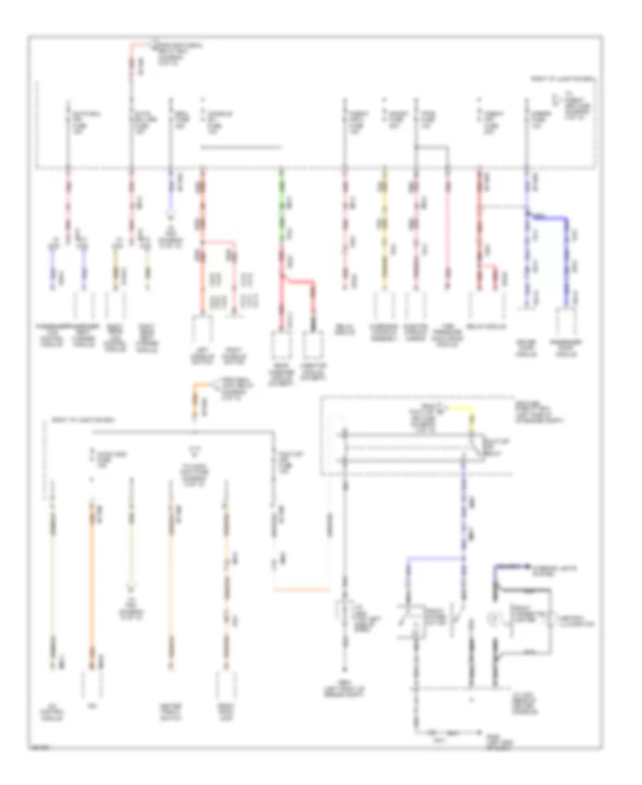 https://portal-diagnostov.com/license.html
Automotive Electricians Portal FZCO
Automotive Electricians Portal FZCO
https://portal-diagnostov.com/license.html
https://portal-diagnostov.com/license.html
Automotive Electricians Portal FZCO
Automotive Electricians Portal FZCOList of elements for Power Distribution Wiring Diagram (8 of 10) for Hyundai Equus Ultimate 2012:
- (left end of dash)
- A/c control module
- A/con (acc) fuse 10a
- Ashtray illumination
- Center fascia switch
- Console sw fuse 10a
- D51-a
- D61-a
- Dd11
- Dd21
- Driver door module
- E/r fuse & relay box (left side of of engine compt)
- Electro chromic mirror
- Em31
- Em41
- Escl fuse 25a
- F15-c f15-a
- F15-d f15-b
- F15-e
- F17-c f17-a
- F17-d f17-b
- F17-e
- Fd11
- Fd21
- Fr11
- Fr21
- From e/r fuse & relay box (diagram 2 of 10)
- From escl (acc) relay (diagram 2 of 10)
- From p/outlet (fr) fuse (diagram 2 of 10)
- Front cigarette lighter
- Front power outlet
- Front room lamp
- Fs11
- Fs41
- Fs51
- Ge03 (left front of engine compt)
- Gm06
- I/p-rha
- I/p-rhb
- I/p-rhc
- I/p-rhd
- Ill
- Interior lights system
- Ipm
- J/c je02 (top left side of dash)
- J/c jm21 (rear of center console)
- Left console switch
- M07-c
- M40-b
- Mf11
- Mf21
- Mirror fuse 10a
- Mm11
- Nca
- Overhead console assembly
- P/outlet (fr) fuse 10a
- P/outlet (fr) relay
- P/seat (fr) fuse 20a
- P/seat (fr)-2 fuse 15a
- Passenger ccs control module
- Passenger door module
- Passenger seat warmer module
- Pnk
- Rear massage module (5:5 seat)
- Red
- Red/
- Relax module
- Right console switch
- Right i/p junction box
- Right rear ccs control module
- Right rear seat warmer module
- S/htd ecu (fr) fuse 15a
- S/htd ecu (rr) fuse 15a
- S/roof fuse 20a
- S146-a
- S174-1
- S46-a
- S70-b
- Ss42
- Tire pressure monitoring module
- To audio (acc) fuse (diagram 9 of 10)
- To p/seat (rr) fuse (diagram 4 of 10)
- To pdm (diagram 10 of 10)
- Tpms fuse 10a
- Vibrator module (5:5 seat)
- W/ ccs
- W/o ccs
Power Distribution Wiring Diagram (9 of 10) for Hyundai Equus Ultimate 2012
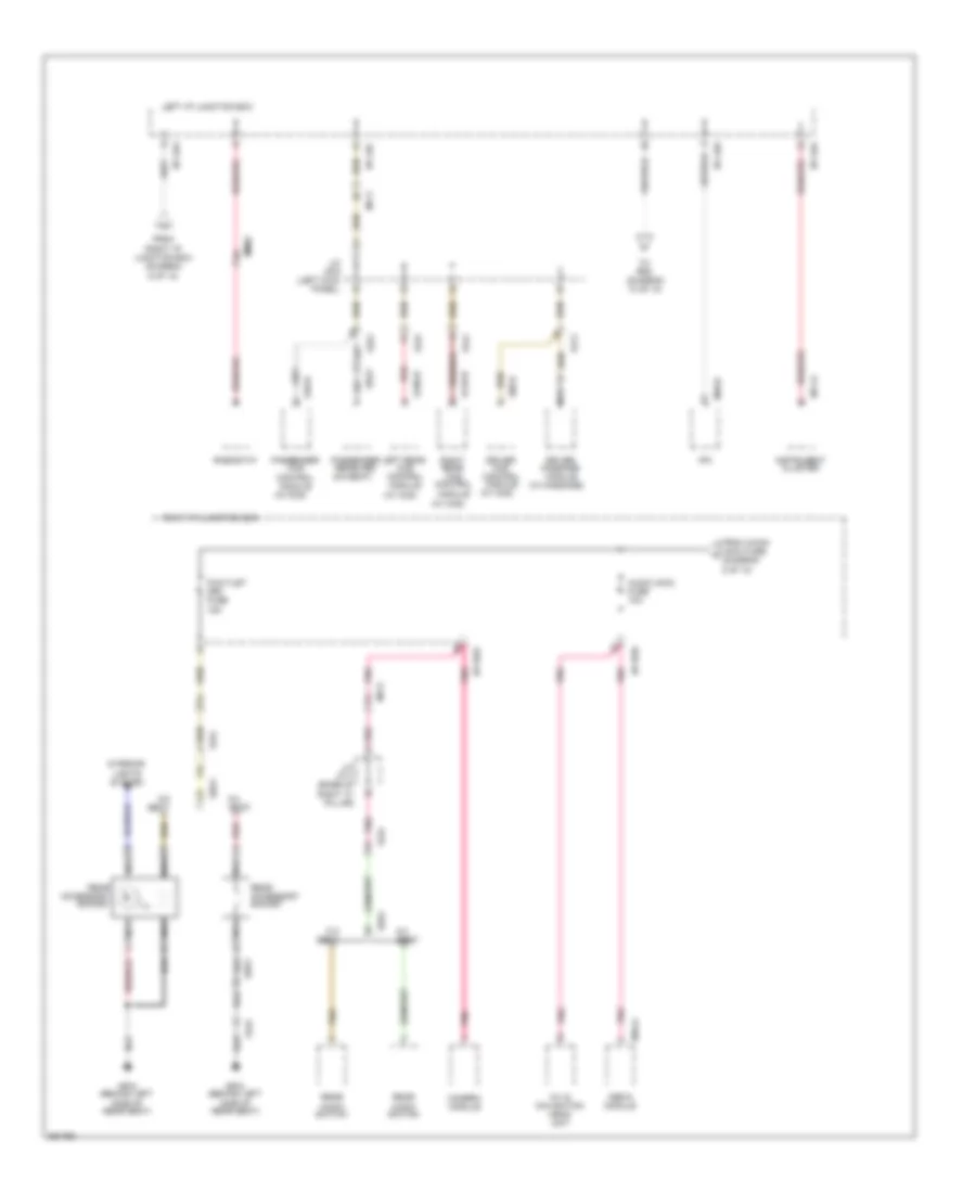 https://portal-diagnostov.com/license.html
Automotive Electricians Portal FZCO
Automotive Electricians Portal FZCO
https://portal-diagnostov.com/license.html
https://portal-diagnostov.com/license.html
Automotive Electricians Portal FZCO
Automotive Electricians Portal FZCOList of elements for Power Distribution Wiring Diagram (9 of 10) for Hyundai Equus Ultimate 2012:
- (5:5 seat)
- (behind left side of rear seat)
- (w/ ccs)
- (w/ massage)
- 5:5 seat
- 6:4 seat
- A/v & navigation head unit
- Audio (acc) fuse 10a
- Camera module
- Driver ccs control module
- Driver massage module
- From a/con (acc) fuse (diagram 8 of 10)
- From right i/p junction box (diagram 6 of 10)
- Fs11
- Fs31
- Fs41
- Fs51
- Gf04
- I/p-lha
- I/p-lhc
- I/p-lhd
- I/p-rhd
- I/p-rhe
- Ill
- Instrument cluster
- Interior lights system
- Ipm
- J/c jf03 (left kick panel)
- J/c jf11 (base of right "c" pillar)
- Left i/p junction box
- Left rear ccs control module
- M11-a
- M40-b
- M45-a
- Media module
- Mf11
- Mf21
- Mm02
- Nca
- P/outlet (rr) fuse 15a
- Passenger ccs control module
- Passenger receiver
- Pnk
- Rear accessory socket
- Rear audio switch
- Red
- Rheostat
- Right i/p junction box
- Right rear ccs control module
- S06-b
- S106-b
- S146-b
- S46-b
- Ss21
- Ss51
- To pdm (diagram 10 of 10)
Power Distribution Wiring Diagram (10 of 10) for Hyundai Equus Ultimate 2012
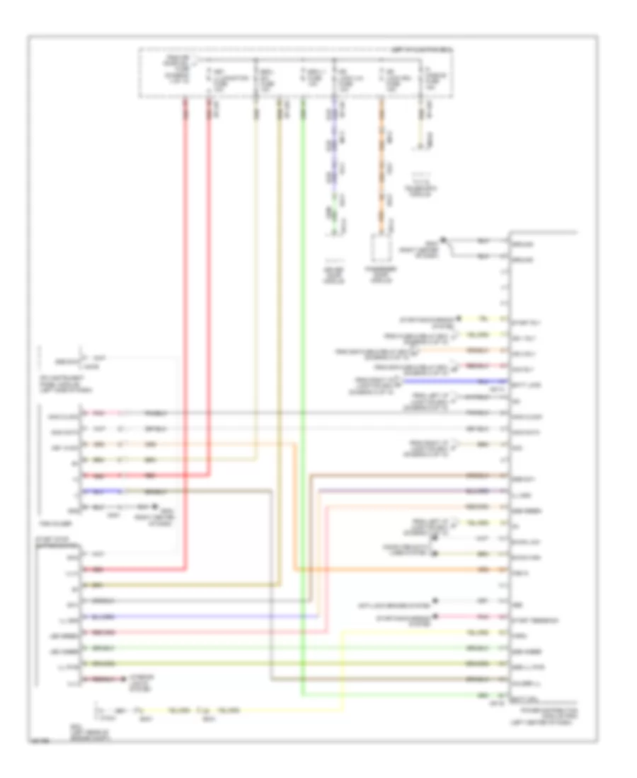 https://portal-diagnostov.com/license.html
Automotive Electricians Portal FZCO
Automotive Electricians Portal FZCO
https://portal-diagnostov.com/license.html
https://portal-diagnostov.com/license.html
Automotive Electricians Portal FZCO
Automotive Electricians Portal FZCOList of elements for Power Distribution Wiring Diagram (10 of 10) for Hyundai Equus Ultimate 2012:
- (+)
- (-)
- (left center of dash)
- (right center
- Abs
- Acc
- Acc rly
- Anti-lock brakes system
- B-can high
- B-can low
- Batt cpu
- Batt load
- Computer data lines system
- Ctg-a
- D51-a
- D61-a
- Dd11
- Dd21
- Dr lock (lh) fuse 10a
- Dr lock (rh) fuse 15a
- Driver door module
- Ec01
- Ecm (left rear of engine compt)
- Em31
- Escl sw fuse 10a
- Escl-1 fuse 10a
- F-rpm
- Fd11
- Fd21
- Fob holder
- Fob in
- From e/r fuse & relay box aa (diagram 2 of 10)
- From e/r fuse & relay box w (diagram 2 of 10)
- From fuse & relay box t (diagram 2 of 10)
- From left i/p r junction box (diagram 7 of 10)
- From left i/p u junction box (diagram 9 of 10)
- From right i/p junction box (diagram 8 of 10)
- From right i/p m junction box (diagram 8 of 10)
- From rr door mdl j
- Fuse (diagram 4 of 10)
- Gm04
- Gm04 (right center of dash)
- Gnd
- Ground
- Holder ill
- I/p-lhe
- I/p-lhf
- Ig1
- Ig2
- Ign 1 rly
- Ign 2 rly
- Ill gnd
- Ill pwr
- Ill(+)
- Ill(-)
- Immo clock
- Immo data
- Interior lights system
- Ipm (instrument panel module) (left side of dash)
- Key illumination fuse 10a
- Key in sw
- Led amber
- Led green
- Left i/p junction box
- M40-b
- M51-a
- M51-b
- M70-b
- Mf11
- Mf21
- Mm01
- Of dash)
- P/ handle fuse 15a
- Passenger door module
- Pnk
- Power distribution module (pdm)
- Red
- Ssb amber
- Ssb green
- Ssb ill pwr
- Ssb sw1
- Ssb sw2
- Start feedback
- Start rly
- Start stop button switch
- Starting/charging system
- Sw1
- Sw2
- Tilt & telescopic module
POWER DOOR LOCKS
Power Door Locks Wiring Diagram (1 of 4) for Hyundai Equus Ultimate 2012
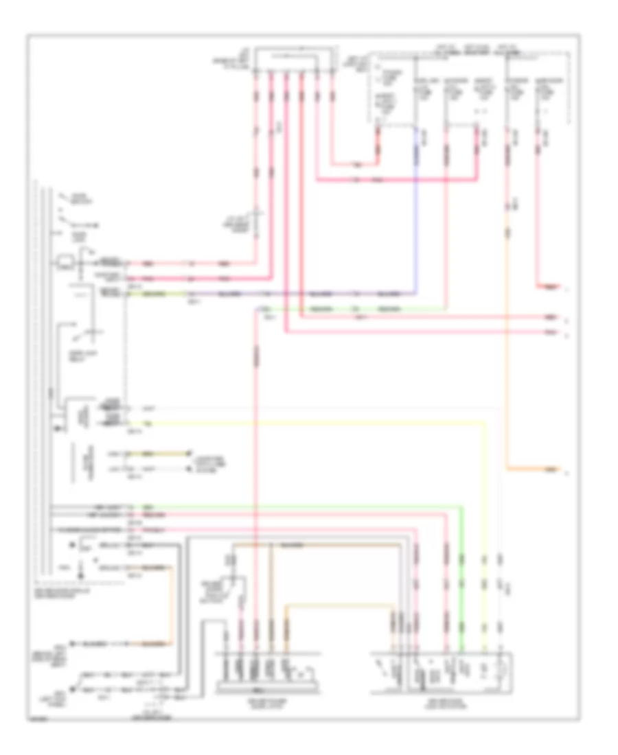 https://portal-diagnostov.com/license.html
Automotive Electricians Portal FZCO
Automotive Electricians Portal FZCO
https://portal-diagnostov.com/license.html
https://portal-diagnostov.com/license.html
Automotive Electricians Portal FZCO
Automotive Electricians Portal FZCOList of elements for Power Door Locks Wiring Diagram (1 of 4) for Hyundai Equus Ultimate 2012:
- Ajar switch
- Body unit-1 fuse 10a
- Body unit-2 fuse 10a
- Computer data lines system
- Cpu
- D51-a
- D51-b
- D51-c
- Dd11
- Door lock
- Door lock relay
- Door lock/ips
- Door unlock
- Door unlock relay
- Dr lock (lh) fuse 10a
- Driver door lock actuator
- Driver door module (driver's door)
- Driver door pawl switch
- Driver power door latch
- Ecu
- Fd11
- Fet
- Fl door unlock state
- Gf01 (left kick panel)
- Gf04 (behind left side of rear seat)
- Ground
- Ground signal
- High
- Hot at all times
- Hot in on or start
- I/p-lhc
- I/p-lhf
- I/p-lhg
- J/c jd11 (driver's door)
- J/c jf01 (base of left "c" pillar)
- Key
- Key lock
- Key unlock
- Left i/p junction box
- Lock
- Low
- Memory power
- Mf11
- On/start input
- P/conn fuse 30a
- P/door (fl) fuse 15a
- P/door (rl) fuse 15a
- Pnk
- Power memory
- Red
- Reg
- Rr door mdl fuse 10a
- Switch ajar
- Switch pawl
- Transceiver b-can
- Unlock
Power Door Locks Wiring Diagram (2 of 4) for Hyundai Equus Ultimate 2012
 https://portal-diagnostov.com/license.html
Automotive Electricians Portal FZCO
Automotive Electricians Portal FZCO
https://portal-diagnostov.com/license.html
https://portal-diagnostov.com/license.html
Automotive Electricians Portal FZCO
Automotive Electricians Portal FZCOList of elements for Power Door Locks Wiring Diagram (2 of 4) for Hyundai Equus Ultimate 2012:
- (left rear door) left rear door module
- Cpu
- Dd31
- Dr lk
- Dr unlk
- Ecu
- Fd31
- Gf02 (left "b" pillar)
- Ground
- Ground signal
- J/c jd31 (left rear door)
- Left rear door lock actuator
- Left rear door pawl switch
- Left rear power door latch
- Mf11
- Pnk
- Power memory
- Red
- Reg
- Switch ajar
- Switch pawl
- Unlock state rl door
Power Door Locks Wiring Diagram (3 of 4) for Hyundai Equus Ultimate 2012
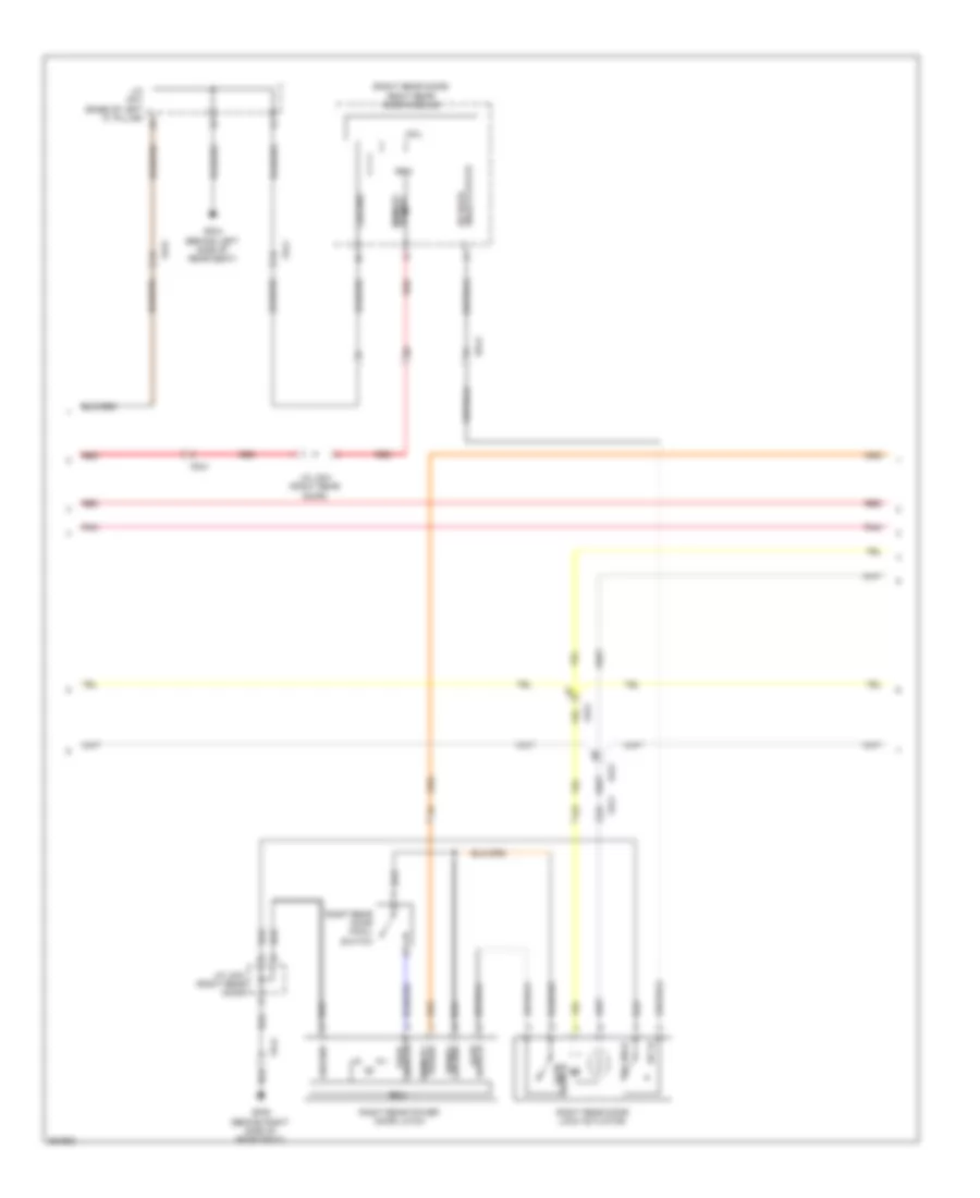 https://portal-diagnostov.com/license.html
Automotive Electricians Portal FZCO
Automotive Electricians Portal FZCO
https://portal-diagnostov.com/license.html
https://portal-diagnostov.com/license.html
Automotive Electricians Portal FZCO
Automotive Electricians Portal FZCOList of elements for Power Door Locks Wiring Diagram (3 of 4) for Hyundai Equus Ultimate 2012:
- (right rear door) right rear door module
- Cpu
- Dd41
- Dr lk
- Dr unlk
- Ecu
- Fd21
- Fd31
- Fd41
- Gf04 (behind left side of rear seat)
- Gf09 (behind right side of rear seat)
- Ground
- Ground signal
- J/c jd41 (right rear door)
- J/c jf01 (base of left "c" pillar)
- Pnk
- Power memory
- Red
- Reg
- Right rear door lock actuator
- Right rear door pawl switch
- Right rear power door latch
- Switch ajar
- Switch pawl
- Unlock state rr door
Power Door Locks Wiring Diagram (4 of 4) for Hyundai Equus Ultimate 2012
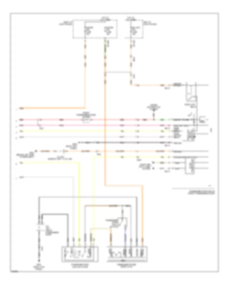 https://portal-diagnostov.com/license.html
Automotive Electricians Portal FZCO
Automotive Electricians Portal FZCO
https://portal-diagnostov.com/license.html
https://portal-diagnostov.com/license.html
Automotive Electricians Portal FZCO
Automotive Electricians Portal FZCOList of elements for Power Door Locks Wiring Diagram (4 of 4) for Hyundai Equus Ultimate 2012:
- (front passenger's door) j/c jd21
- Computer data lines system
- Cpu
- D61-a
- D61-c
- Dd21
- Door lock
- Door lock relay door unlock relay
- Dr lk
- Dr lock (rh) fuse 15a
- Dr unlk
- Driver ips motor door lock
- Ecu
- Fd21
- Fr door unlock state
- Gf04 (behind left side of rear seat)
- Gf05 (right kick panel)
- Ground
- Ground signal
- High
- Hot at all times
- I/p-lhe
- I/p-rhe
- J/c jd21 (front passenger's door)
- J/c jf01 (base of left "c" pillar)
- Left i/p junction box
- Low
- Memory power
- Mf21
- On/start input
- P/door (fr) fuse 15a
- P/door (rr) fuse 15a
- Passenger door lock actuator
- Passenger door module (front passenger's door)
- Passenger door pawl switch
- Passenger power door latch
- Pnk
- Power distribution system
- Power memory
- Red
- Reg
- Relay
- Right i/p junction box
- Switch ajar
- Switch pawl
- Transceiver b-can
POWER MIRRORS
Electrochromic Mirror Wiring Diagram for Hyundai Equus Ultimate 2012
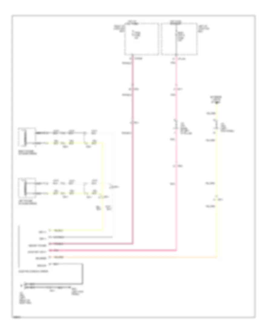 https://portal-diagnostov.com/license.html
Automotive Electricians Portal FZCO
Automotive Electricians Portal FZCO
https://portal-diagnostov.com/license.html
https://portal-diagnostov.com/license.html
Automotive Electricians Portal FZCO
Automotive Electricians Portal FZCOList of elements for Electrochromic Mirror Wiring Diagram for Hyundai Equus Ultimate 2012:
- Body unit-2 fuse 10a
- Dd11
- Dd21
- Ecm mirror
- Electro chromic mirror
- Exterior
- Fd11
- Fd21
- Fr11
- Fr21
- Gf01 (left kick panel)
- Ground
- Hot at all times
- Hot in on or start
- I/p-lhg
- I/p-rhb
- J/c jf01 (base of left "c" pillar)
- J/c jf03 (left kick panel)
- J/c jr01 (left front of roof trim)
- Left i/p junction box
- Left power outside mirror
- Lights sytsem
- Memory power
- Mf11
- Mf21
- Nca +
- Nca -
- Oec (+)
- Oec (-)
- On/start input
- Pnk
- Reverse
- Right i/p junction box
- Right power outside mirror
- Tpms fuse 10a
Power Mirrors Wiring Diagram for Hyundai Equus Ultimate 2012
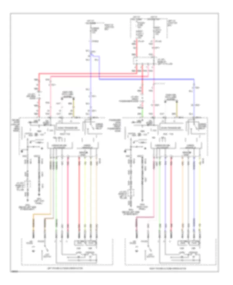 https://portal-diagnostov.com/license.html
Automotive Electricians Portal FZCO
Automotive Electricians Portal FZCO
https://portal-diagnostov.com/license.html
https://portal-diagnostov.com/license.html
Automotive Electricians Portal FZCO
Automotive Electricians Portal FZCOList of elements for Power Mirrors Wiring Diagram for Hyundai Equus Ultimate 2012:
- B-can transceiver
- Body unit-1 fuse 10a
- Body unit-2 fuse 10a
- Computer data lines system
- Cpu
- D51-a
- D51-b
- D51-c
- D61-a
- D61-b
- D61-c
- Dd11
- Dd21
- Dog
- Driver door module (dri- ver's door)
- Fd11
- Fd21
- Fet
- Fold'g
- Gf01 (left kick panel)
- Gf04 (behind left side of rear seat)
- Gf05 (right kick panel)
- Gnd
- Hor
- Hot at all times
- Hot in on or start
- I/p-lhf
- I/p-lhg
- I/p-rhd
- Irq
- J/c jd11 (driver's door)
- J/c jd21 (front passenger's door)
- J/c jf01 (base of left "c" pillar)
- Left i/p junction box
- Left power outside mirror motor
- Lh/rh
- Limt
- Mem pwr
- Mf11
- Mirror driver/ folding/ips
- Mirror fuse 10a
- Mirror power relay
- Mirror sensor i/f
- Nca
- On/ start input
- P/conn fuse 30a
- Passenger door module (front passenger's door)
- Pnk
- Re- set
- Red
- Reg
- Right i/p junction box
- Right power outside mirror motor
- Rxd
- Sens gnd
- Switch
- Txd
- Un- fold'g
- Up/down
- Vcc
- Ver
- Watch-
POWER SEATS
Climate Control Seats Wiring Diagram, 5:5 Seat (1 of 4) for Hyundai Equus Ultimate 2012
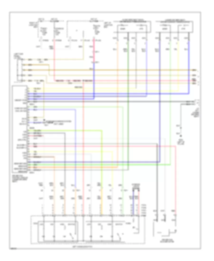 https://portal-diagnostov.com/license.html
Automotive Electricians Portal FZCO
Automotive Electricians Portal FZCO
https://portal-diagnostov.com/license.html
https://portal-diagnostov.com/license.html
Automotive Electricians Portal FZCO
Automotive Electricians Portal FZCOList of elements for Climate Control Seats Wiring Diagram, 5:5 Seat (1 of 4) for Hyundai Equus Ultimate 2012:
- (+)
- (-)
- (in driver's seat back) driver back thermocouple
- (left kick panel) j/c jf03
- (not used)
- (under driver's seat) driver cushion thermocouple
- Alt l
- Blower (+)
- Blower (-)
- Body unit fuse 10a
- Console sw fuse 10a
- Cool
- Cool sw sig
- Driver ccs blower motor
- Driver ccs control module (under driver's seat)
- F15-a
- F15-b
- F15-c
- F15-d
- F15-e
- Fs11
- Gf02 (left "b" pillar)
- Gnd
- High
- Hot at all times
- Hot in on
- Htr
- I/p-lha
- I/p-lhc
- I/p-lhg
- I/p-rhb
- I/p-rhd
- Ill
- Interior lights system
- Iso 9141
- J/c js11 (under driver's seat)
- Left console switch
- Left i/p junction box
- Low
- Memory pwr
- Mf11
- Mf21
- Mid
- Nca
- On in
- Pnk
- Red
- Right i/p junction box
- S/htd ecu (fl) fuse 15a
- S06-a
- S06-b
- S06-c
- Sens return
- Sens sig
- Snsr
- Spd ctrl
- Starting/charging system
- Switch
- Warm
- Warm sw sig
Climate Control Seats Wiring Diagram, 5:5 Seat (2 of 4) for Hyundai Equus Ultimate 2012
 https://portal-diagnostov.com/license.html
Automotive Electricians Portal FZCO
Automotive Electricians Portal FZCO
https://portal-diagnostov.com/license.html
https://portal-diagnostov.com/license.html
Automotive Electricians Portal FZCO
Automotive Electricians Portal FZCOList of elements for Climate Control Seats Wiring Diagram, 5:5 Seat (2 of 4) for Hyundai Equus Ultimate 2012:
- (+)
- (-)
- (bottom of passenger's seat)
- (left side of front passenger seat back) passenger back thermocouple
- (passenger's seat) passenger cushion thermocouple
- Alt l
- Audio (b+) fuse 15a
- Blower (+)
- Blower (-)
- Cool
- Cool sw sig
- F17-a
- F17-b
- F17-c
- F17-d
- F17-e
- Fs11
- Fs31
- Fs41
- Fs51
- Gf06 (right "b" pillar)
- Gnd
- High
- Hot at all times
- Htr
- I/p-lhc
- I/p-lhg
- I/p-rha
- Ill
- Interior lights system
- J/c jm01 (center of dash)
- J/c js21 (bottom of passenger's seat)
- Left i/p junction box
- Low
- Memory pwr
- Mf11
- Mf21
- Mid
- Nca
- On in
- P/conn fuse 30a
- Passenger ccs blower motor
- Passenger ccs control module
- Pnk
- Red
- Right console switch
- Right i/p junction box
- S/htd ecu (fr) fuse 15a
- S/htd ecu (rl) fuse 15a
- S/htd ecu (rr) fuse 15a
- S46-a
- S46-b
- S46-c
- Sens return
- Sens sig
- Snsr
- Spd ctrl
- Starting/charging system
- Switch
- Warm
- Warm sw sig
Climate Control Seats Wiring Diagram, 5:5 Seat (3 of 4) for Hyundai Equus Ultimate 2012
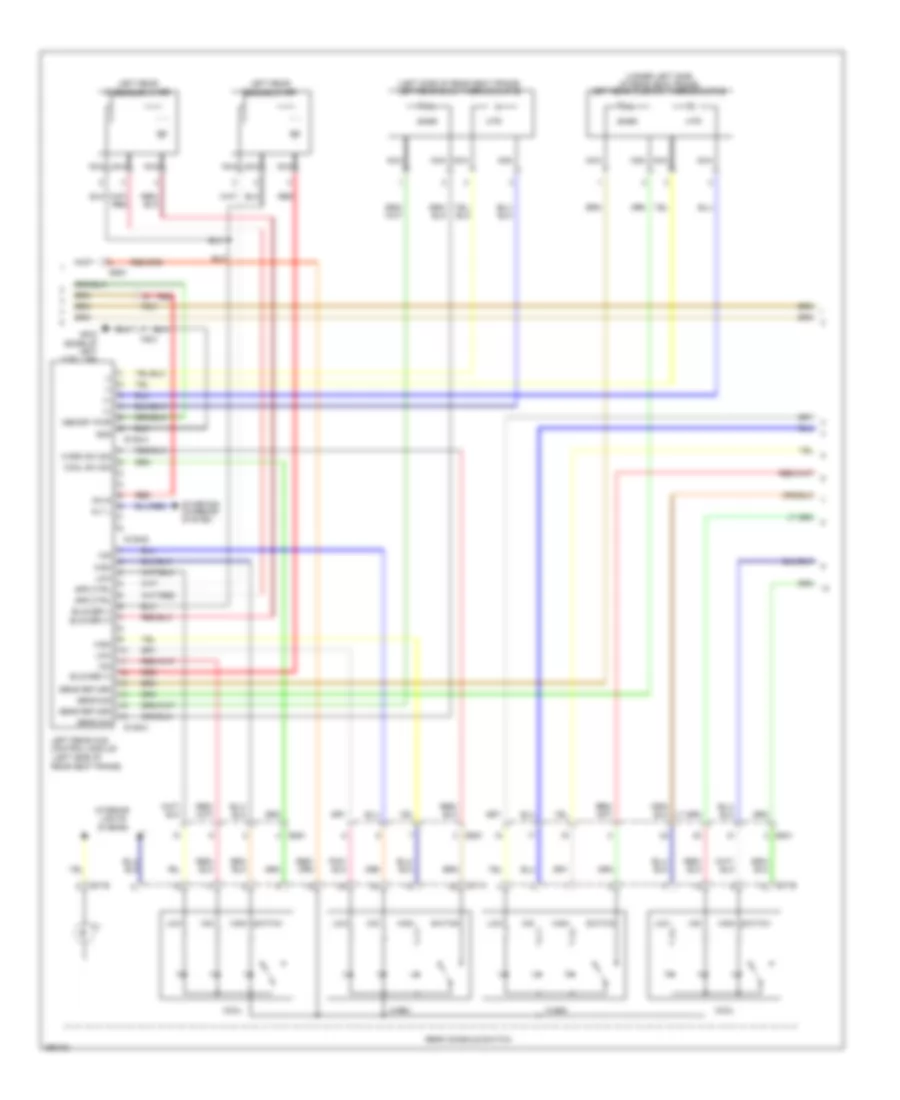 https://portal-diagnostov.com/license.html
Automotive Electricians Portal FZCO
Automotive Electricians Portal FZCO
https://portal-diagnostov.com/license.html
https://portal-diagnostov.com/license.html
Automotive Electricians Portal FZCO
Automotive Electricians Portal FZCOList of elements for Climate Control Seats Wiring Diagram, 5:5 Seat (3 of 4) for Hyundai Equus Ultimate 2012:
- (+)
- (-)
- (left side of rear seat frame)
- (left side of rear seat frame) left rear back thermocouple
- (under left side of rear seat frame) left rear cushion thermocouple
- Alt l
- Blower (+)
- Blower (-)
- Cool
- Cool sw sig
- Fs31
- Gf03 (base of left "c"pillar)
- Gnd
- High
- Htr
- Ill
- Interior lights system
- Left rear back blower
- Left rear ccs control module
- Left rear cushion blower
- Low
- Memory pwr
- Mid
- Nca
- On in
- Rear console switch
- Red
- S106-a
- S106-b
- S106-c
- S37-a
- S37-b
- Sens return
- Sens sig
- Snsr
- Spd ctrl
- Ss41
- Ss51
- Starting/ charging system
- Switch
- Warm
- Warm sw sig
Climate Control Seats Wiring Diagram, 5:5 Seat (4 of 4) for Hyundai Equus Ultimate 2012
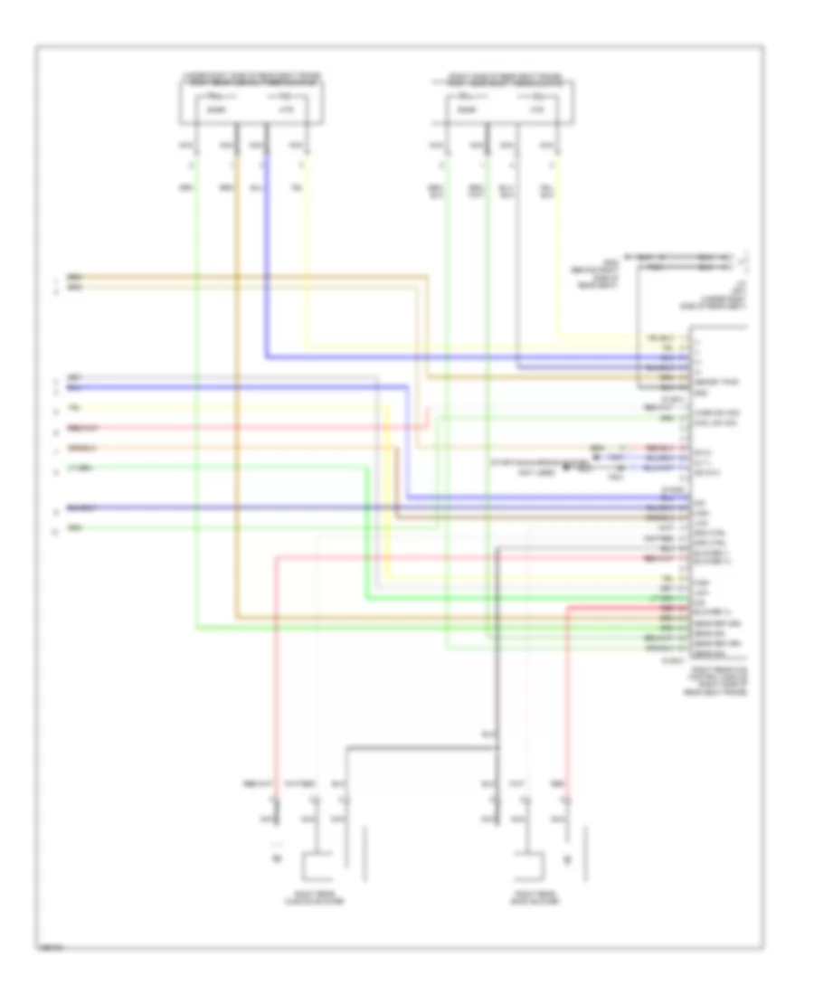 https://portal-diagnostov.com/license.html
Automotive Electricians Portal FZCO
Automotive Electricians Portal FZCO
https://portal-diagnostov.com/license.html
https://portal-diagnostov.com/license.html
Automotive Electricians Portal FZCO
Automotive Electricians Portal FZCOList of elements for Climate Control Seats Wiring Diagram, 5:5 Seat (4 of 4) for Hyundai Equus Ultimate 2012:
- (+)
- (-)
- (not used)
- (right side of rear seat frame) right rear back thermocouple
- (under right side of rear seat frame) right rear cushion thermocouple
- Alt l
- Blower (+)
- Blower (-)
- Cool sw sig
- Fs41
- Gf08 (behind right side of rear seat)
- Gnd
- High
- Htr
- Iso 9141
- J/c js41 (under right side of rear seat)
- Low
- Memory pwr
- Mid
- Nca
- On in
- Red
- Right rear back blower
- Right rear ccs control module (right side of rear seat frame)
- Right rear cushion blower
- S146-a
- S146-b
- S146-c
- Sens return
- Sens sig
- Snsr
- Spd ctrl
- Starting/charging system
- Warm sw sig
Climate Control Seats Wiring Diagram, 6:4 Seat (1 of 4) for Hyundai Equus Ultimate 2012
 https://portal-diagnostov.com/license.html
Automotive Electricians Portal FZCO
Automotive Electricians Portal FZCO
https://portal-diagnostov.com/license.html
https://portal-diagnostov.com/license.html
Automotive Electricians Portal FZCO
Automotive Electricians Portal FZCOList of elements for Climate Control Seats Wiring Diagram, 6:4 Seat (1 of 4) for Hyundai Equus Ultimate 2012:
- (+)
- (-)
- (in driver's seat back) driver back thermocouple
- (left kick panel) j/c jf03
- (not used)
- (under driver's seat) driver cushion thermocouple
- Alt l
- Blower (+)
- Blower (-)
- Body unit fuse 10a
- Console sw fuse 10a
- Cool
- Cool sw
- Driver ccs blower motor
- Driver ccs control module (under driver's seat)
- F15-a
- F15-b
- F15-c
- F15-d
- F15-e
- Fs11
- Gf02 (left "b" pillar)
- Gnd
- High
- Hot at all times
- Hot in on
- Htr
- I/p-lha
- I/p-lhc
- I/p-lhg
- I/p-rhb
- I/p-rhd
- Ill
- Interior lights system
- Iso 9141
- J/c js11 (under driver's seat)
- Left console switch
- Left i/p junction box
- Low
- Memory pwr
- Mf11
- Mf21
- Mid
- Nca
- On in
- Pnk
- Red
- Right i/p junction box
- S/htd ecu (fl) fuse 15a
- S06-a
- S06-b
- S06-c
- Sens return
- Sens sig
- Snsr
- Spd ctrl
- Starting/charging system
- Switch
- Warm
- Warm sw sig
Climate Control Seats Wiring Diagram, 6:4 Seat (2 of 4) for Hyundai Equus Ultimate 2012
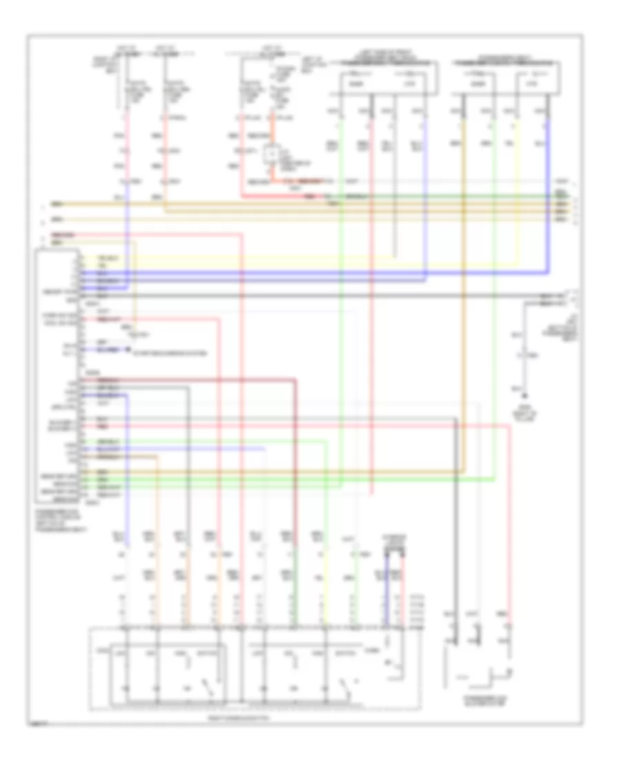 https://portal-diagnostov.com/license.html
Automotive Electricians Portal FZCO
Automotive Electricians Portal FZCO
https://portal-diagnostov.com/license.html
https://portal-diagnostov.com/license.html
Automotive Electricians Portal FZCO
Automotive Electricians Portal FZCOList of elements for Climate Control Seats Wiring Diagram, 6:4 Seat (2 of 4) for Hyundai Equus Ultimate 2012:
- (+)
- (-)
- (bottom of passenger's seat)
- (left side of front passenger seat back) passenger back thermocouple
- (passenger's seat) passenger cushion thermocouple
- Alt l
- Audio (b+) fuse 15a
- Blower (+)
- Blower (-)
- Cool
- Cool sw sig
- F17-a
- F17-b
- F17-c
- F17-d
- F17-e
- Fs11
- Fs31
- Fs41
- Fs51
- Gf06 (right "b" pillar)
- Gnd
- High
- Hot at all times
- Htr
- I/p-lhc
- I/p-lhg
- I/p-rha
- Ill
- Interior lights system
- J/c jm01 (center of dash)
- J/c js21 (bottom of passenger's seat)
- Left i/p junction box
- Low
- Memory pwr
- Mf11
- Mf21
- Mid
- Nca
- On in
- P/conn fuse 30a
- Passenger ccs blower motor
- Passenger ccs control module
- Pnk
- Red
- Right console switch
- Right i/p junction box
- S/htd ecu (fr) fuse 15a
- S/htd ecu (rl) fuse 15a
- S/htd ecu (rr) fuse 15a
- S46-a
- S46-b
- S46-c
- Sens return
- Sens sig
- Snsr
- Spd ctrl
- Starting/charging system
- Switch
- Warm
- Warm sw sig
Climate Control Seats Wiring Diagram, 6:4 Seat (3 of 4) for Hyundai Equus Ultimate 2012
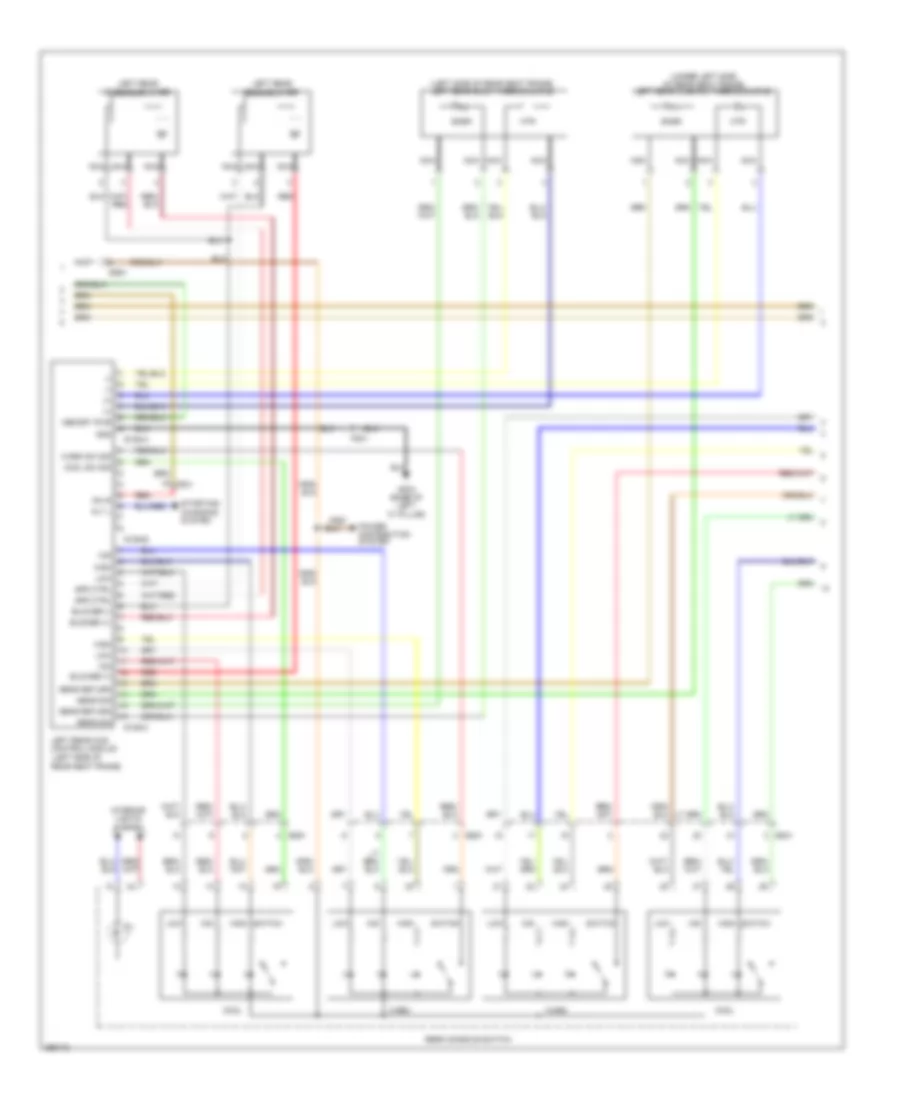 https://portal-diagnostov.com/license.html
Automotive Electricians Portal FZCO
Automotive Electricians Portal FZCO
https://portal-diagnostov.com/license.html
https://portal-diagnostov.com/license.html
Automotive Electricians Portal FZCO
Automotive Electricians Portal FZCOList of elements for Climate Control Seats Wiring Diagram, 6:4 Seat (3 of 4) for Hyundai Equus Ultimate 2012:
- (+)
- (-)
- (left side of rear seat frame)
- (left side of rear seat frame) left rear back thermocouple
- (under left side of rear seat frame) left rear cushion thermocouple
- Alt l
- Blower (+)
- Blower (-)
- Cool
- Cool sw sig
- Fs31
- Gf03 (base of left "c" pillar)
- Gnd
- High
- Htr
- Ill
- Interior lights system
- Left rear back blower
- Left rear ccs control module
- Left rear cushion blower
- Low
- Memory pwr
- Mid
- Nca
- On in
- Power distribution system
- Rear console switch
- Red
- S106-a
- S106-b
- S106-c
- Sens return
- Sens sig
- Snsr
- Spd ctrl
- Ss41
- Ss51
- Starting/ changing system
- Switch
- Warm
- Warm sw sig
Climate Control Seats Wiring Diagram, 6:4 Seat (4 of 4) for Hyundai Equus Ultimate 2012
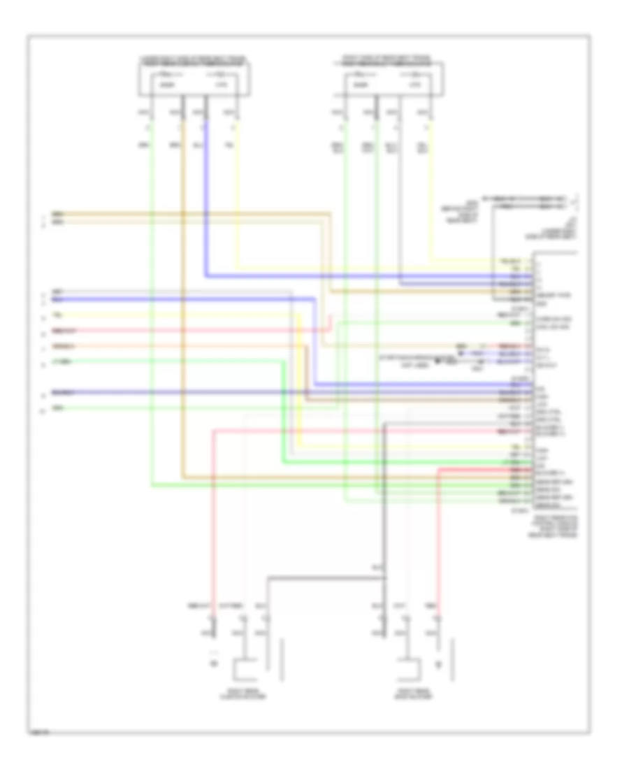 https://portal-diagnostov.com/license.html
Automotive Electricians Portal FZCO
Automotive Electricians Portal FZCO
https://portal-diagnostov.com/license.html
https://portal-diagnostov.com/license.html
Automotive Electricians Portal FZCO
Automotive Electricians Portal FZCOList of elements for Climate Control Seats Wiring Diagram, 6:4 Seat (4 of 4) for Hyundai Equus Ultimate 2012:
- (+)
- (-)
- (not used)
- (right side of rear seat frame) right rear back thermocouple
- (under right side of rear seat frame) right rear cushion thermocouple
- Alt l
- Blower (+)
- Blower (-)
- Cool sw sig
- Fs41
- Gf08 (behind right side of rear seat)
- Gnd
- High
- Htr
- Iso 9141
- J/c js41 (under right side of rear seat)
- Low
- Memory pwr
- Mid
- Nca
- On in
- Red
- Right rear back blower
- Right rear ccs control module (right side of rear seat frame)
- Right rear cushion blower
- S146-a
- S146-b
- S146-c
- Sens return
- Sens sig
- Snsr
- Spd ctrl
- Starting/charging system
- Warm sw sig
Driver Seat Massage Wiring Diagram for Hyundai Equus Ultimate 2012
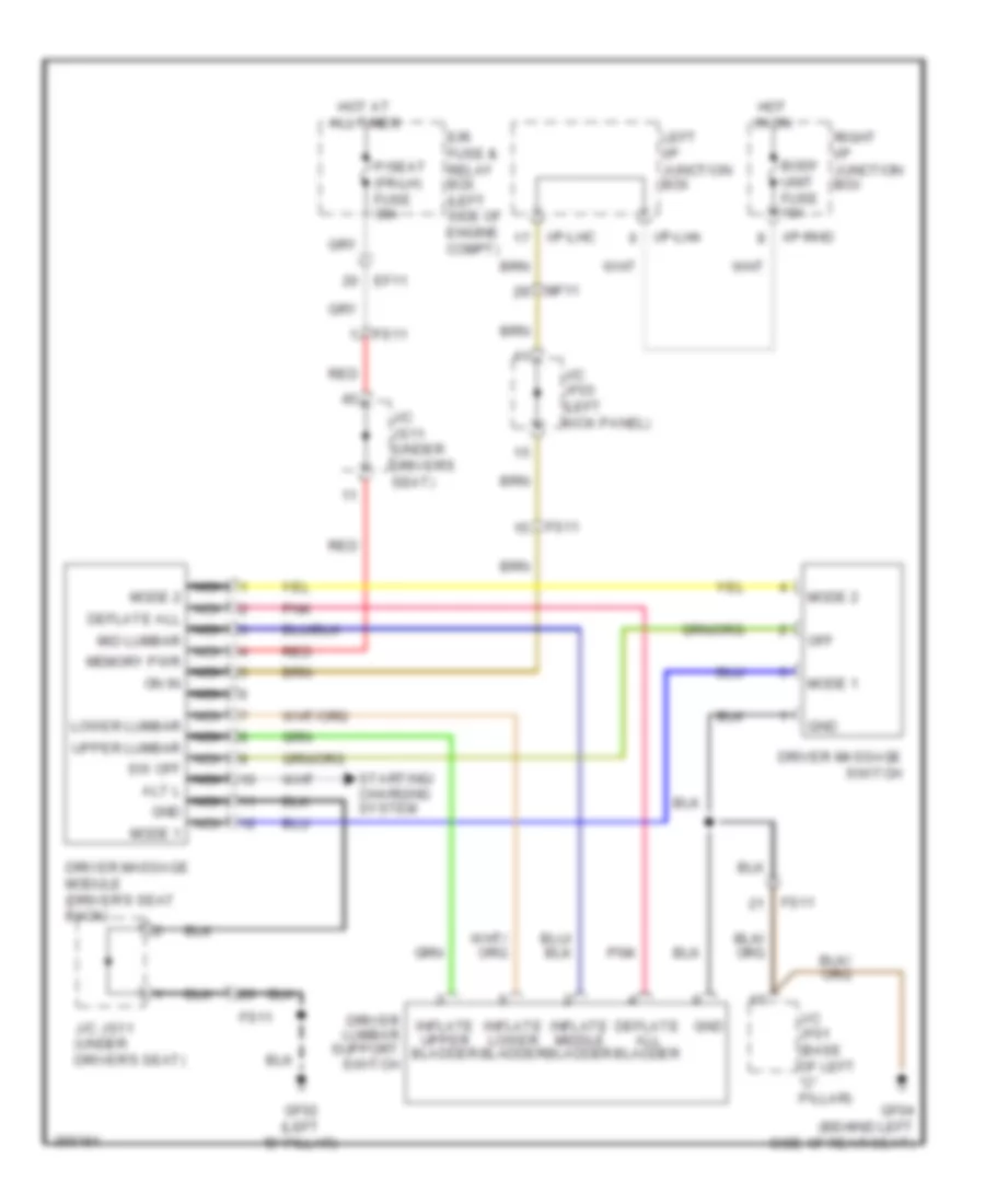 https://portal-diagnostov.com/license.html
Automotive Electricians Portal FZCO
Automotive Electricians Portal FZCO
https://portal-diagnostov.com/license.html
https://portal-diagnostov.com/license.html
Automotive Electricians Portal FZCO
Automotive Electricians Portal FZCOList of elements for Driver Seat Massage Wiring Diagram for Hyundai Equus Ultimate 2012:
- Body unit fuse 10a
- Deflate all bladder
- Driver lumbar support switch
- Driver massage module (driver's seat back)
- Driver massage switch
- E/r fuse & relay box (left side of engine compt)
- Ef11
- Fs11
- Gf02 (left "b" pillar)
- Gf04 (behind left side of rear seat)
- Gnd
- Hot at all times
- Hot in on
- I/p-lha
- I/p-lhc
- I/p-rhd
- Inflate lower bladder
- Inflate middle bladder
- Inflate upper bladder
- J/c jf01 (base of left "c" pillar)
- J/c jf03 (left kick panel)
- J/c js11 (under driver's seat)
- Left i/p junction box
- Mf11
- Mode 1
- Mode 2
- Nca lower lumbar nca upper lumbar nca sw off nca alt l nca gnd nca mode 1
- Nca mode 2 nca deflate all nca mid lumbar nca memory pwr nca on in nca
- Off
- P/seat (fr-lh) fuse 30a
- Pnk
- Red
- Right i/p junction box
- Starting/ charging system
Front Adjustable Seat Warmer Wiring Diagram for Hyundai Equus Ultimate 2012
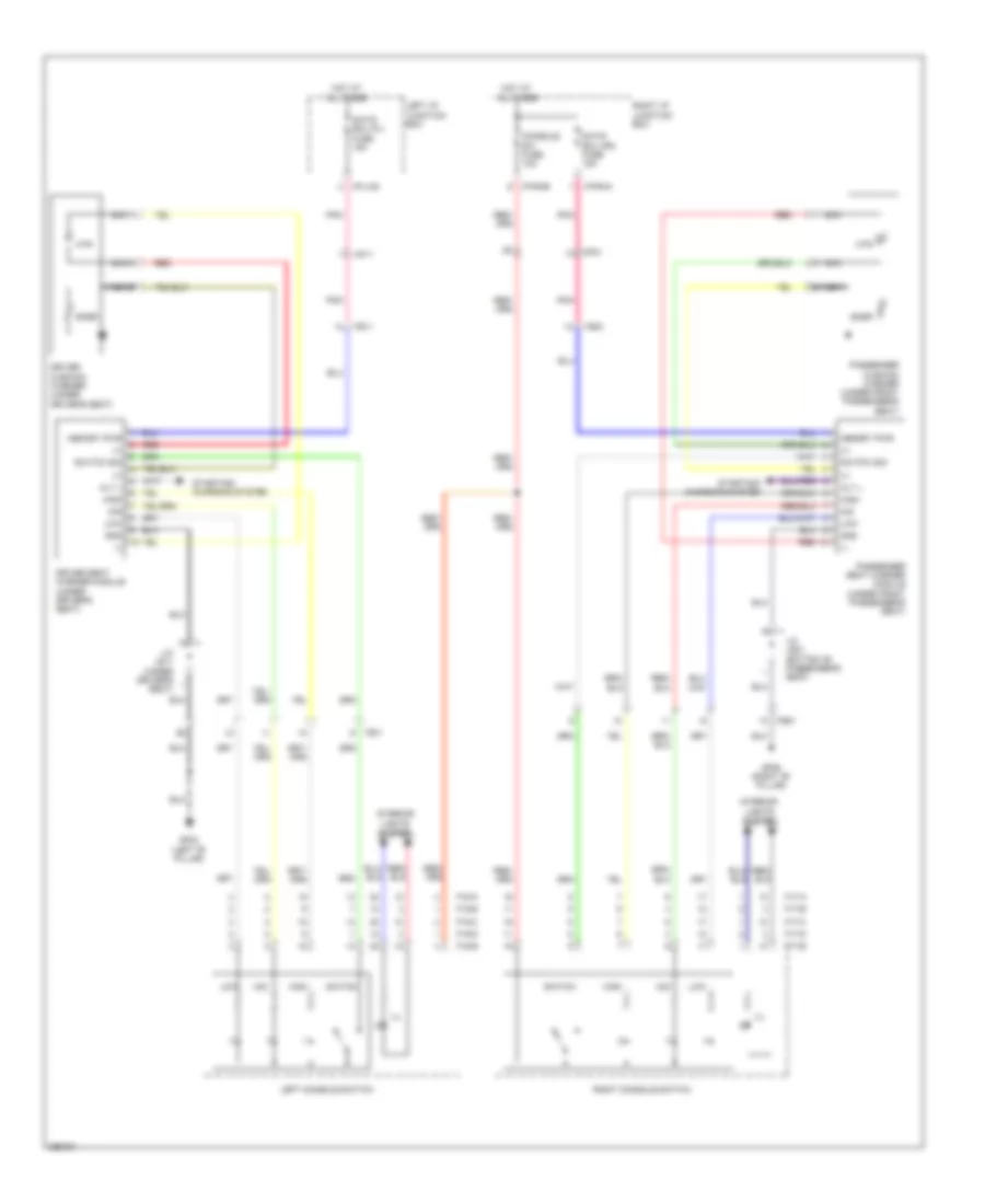 https://portal-diagnostov.com/license.html
Automotive Electricians Portal FZCO
Automotive Electricians Portal FZCO
https://portal-diagnostov.com/license.html
https://portal-diagnostov.com/license.html
Automotive Electricians Portal FZCO
Automotive Electricians Portal FZCOList of elements for Front Adjustable Seat Warmer Wiring Diagram for Hyundai Equus Ultimate 2012:
- (+)
- (-)
- Alt l
- Charging system
- Console sw fuse 10a
- Driver cushion warmer (under driver's seat)
- Driver seat warmer module (under driver's seat)
- F15-a
- F15-b
- F15-c
- F15-d
- F15-e
- F17-a
- F17-b
- F17-c
- F17-d
- F17-e
- Fs11
- Fs51
- Gf02 (left "b" pillar)
- Gf06 (right "b" pillar)
- Gnd
- High
- Hot at all times
- Htr
- I/p-lhg
- I/p-rha
- I/p-rhb
- Ill
- Interior lights system
- J/c js11 (under driver's seat)
- J/c js21 (bottom of passenger's seat)
- Left console switch
- Left i/p junction box
- Low
- Memory pwr
- Mf11
- Mf21
- Mid
- Nca
- Passenger cushion warmer (under front passenger's seat)
- Passenger seat warmer module (under front passenger's seat)
- Pnk
- Red
- Right console switch
- Right i/p junction box
- S/htd ecu (fl) fuse 15a
- S/htd ecu (fr) fuse 15a
- Snsr
- Starting/
- Starting/ charging system
- Switch
- Switch sig
Heated Steering Wheel Wiring Diagram for Hyundai Equus Ultimate 2012
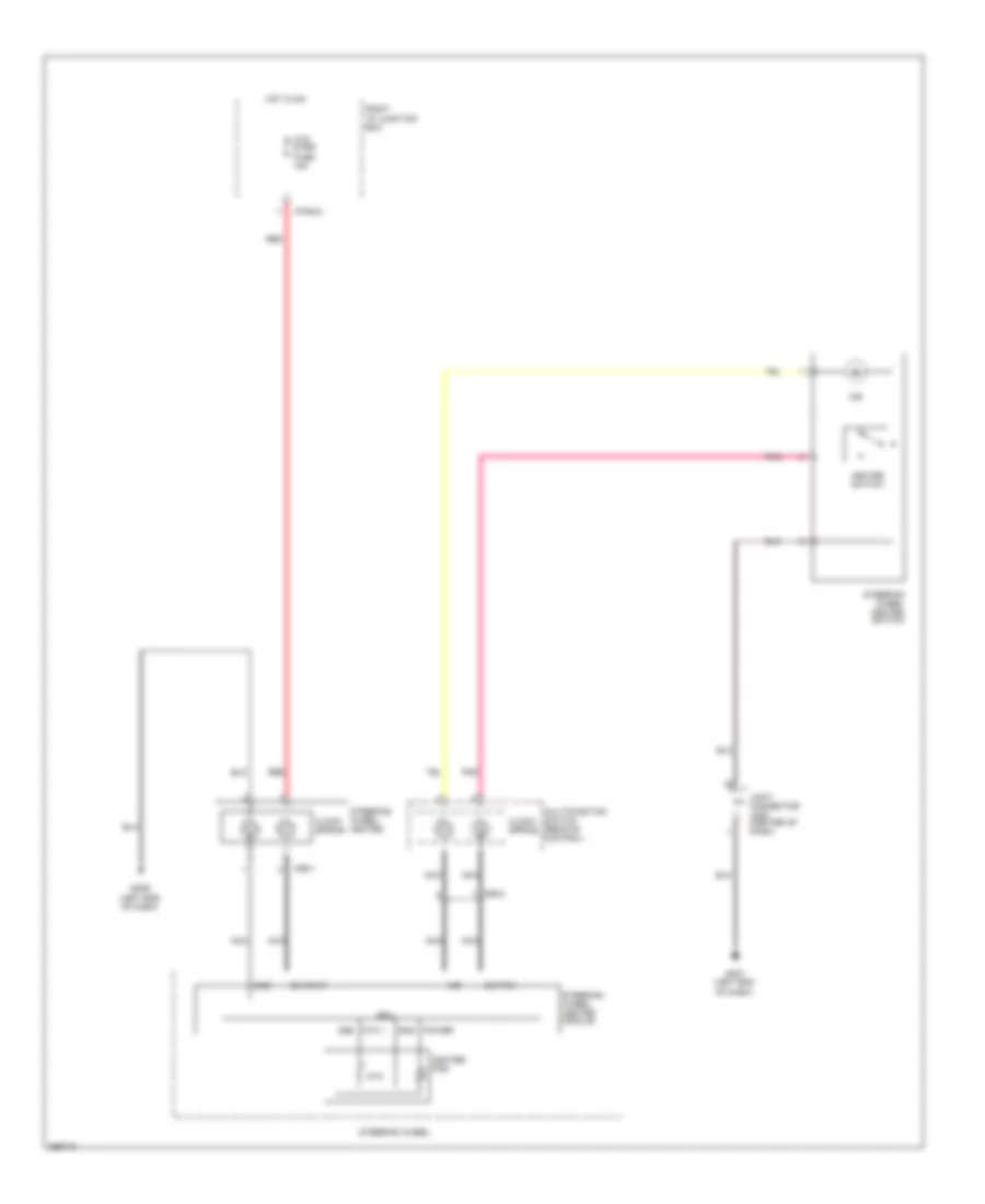 https://portal-diagnostov.com/license.html
Automotive Electricians Portal FZCO
Automotive Electricians Portal FZCO
https://portal-diagnostov.com/license.html
https://portal-diagnostov.com/license.html
Automotive Electricians Portal FZCO
Automotive Electricians Portal FZCOList of elements for Heated Steering Wheel Wiring Diagram for Hyundai Equus Ultimate 2012:
- Clock spring
- Ecu
- Gm01 (left end of dash)
- Gm06 (left end of dash)
- Gnd
- Heated switch
- Heater pad
- Hot in on
- Htd strg fuse 15a
- I/p-rha
- Ind
- Joint connector jm05 (center of dash)
- M98-1
- M98-2
- Multifunction switch (remote control)
- Nca
- Ntc
- Ntc +
- On input
- Pnk
- Power
- Red
- Right i/p junction box
- Steering wheel
- Steering wheel heated
- Steering wheel heated module
- Steering wheel heated switch
- Switch
Rear Adjustable Seat Warmer Wiring Diagram, 5:5 Seat for Hyundai Equus Ultimate 2012
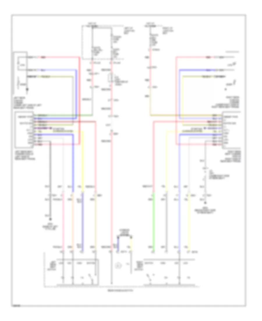 https://portal-diagnostov.com/license.html
Automotive Electricians Portal FZCO
Automotive Electricians Portal FZCO
https://portal-diagnostov.com/license.html
https://portal-diagnostov.com/license.html
Automotive Electricians Portal FZCO
Automotive Electricians Portal FZCOList of elements for Rear Adjustable Seat Warmer Wiring Diagram, 5:5 Seat for Hyundai Equus Ultimate 2012:
- (+)
- (-)
- Alt l
- Audio (b+) fuse 15a
- Charging system
- Fs31
- Fs41
- Gf03 (base of left "c" pillar)
- Gf08 (behind right side of rear seat)
- Gnd
- High
- Hot at all times
- Htr
- I/p-lhc
- I/p-lhg
- I/p-rha
- Ill
- Interior lights system
- J/c jm01 (center of dash)
- J/c js41 (under right side of rear seat)
- Left i/p junction box
- Left rear cushion warmer (under left side of left rear seat frame)
- Left rear seat switch
- Left rear seat warmer module (left side of rear seat frame)
- Low
- Memory pwr
- Mf11
- Mf21
- Mid
- Nca
- P/conn fuse 30a
- Rear console switch
- Red
- Right i/p junction box
- Right rear cushion warmer (under right side of right rear seat frame)
- Right rear seat warmer module (right side of rear seat frame)
- Right switch rear seat switch
- S/htd ecu (rl) fuse 15a
- S/htd ecu (rr) fuse 15a
- S37-a
- S37-b
- Snsr
- Ss41
- Ss51
- Starting/
- Starting/ charging system
- Switch
- Switch sig
Rear Adjustable Seat Warmer Wiring Diagram, 6:4 Seat for Hyundai Equus Ultimate 2012
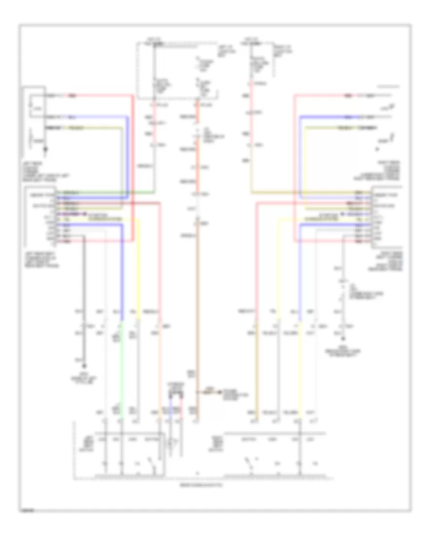 https://portal-diagnostov.com/license.html
Automotive Electricians Portal FZCO
Automotive Electricians Portal FZCO
https://portal-diagnostov.com/license.html
https://portal-diagnostov.com/license.html
Automotive Electricians Portal FZCO
Automotive Electricians Portal FZCOList of elements for Rear Adjustable Seat Warmer Wiring Diagram, 6:4 Seat for Hyundai Equus Ultimate 2012:
- (+)
- (-)
- Alt l
- Audio (b+) fuse 15a
- Charging system
- Fs31
- Fs41
- Gf03 (base of left "c" pillar)
- Gf08 (behind right side of rear seat)
- Gnd
- High
- Hot at all times
- Htr
- I/p-lhc
- I/p-lhg
- I/p-rha
- Ill
- Interior lights system
- J/c jm01 (center of dash)
- J/c js41 (under right side of rear seat)
- Left i/p junction box
- Left rear cushion warmer (under left side of left rear seat frame)
- Left rear seat switch
- Left rear seat warmer module (left side of rear seat frame)
- Low
- Memory pwr
- Mf11
- Mf21
- Mid
- Nca
- P/conn fuse 30a
- Power distribution system
- Rear console switch
- Red
- Right i/p junction box
- Right rear cushion warmer (under right side of right rear seat frame)
- Right rear seat switch
- Right rear seat warmer module (right side of rear seat frame)
- S/htd ecu (rl) fuse 15a
- S/htd ecu (rr) fuse 15a
- Snsr
- Ss41
- Ss51
- Starting/
- Starting/ charging system
- Switch
- Switch sig
Rear Power Seat Wiring Diagram, 5:5 Seat (1 of 2) for Hyundai Equus Ultimate 2012
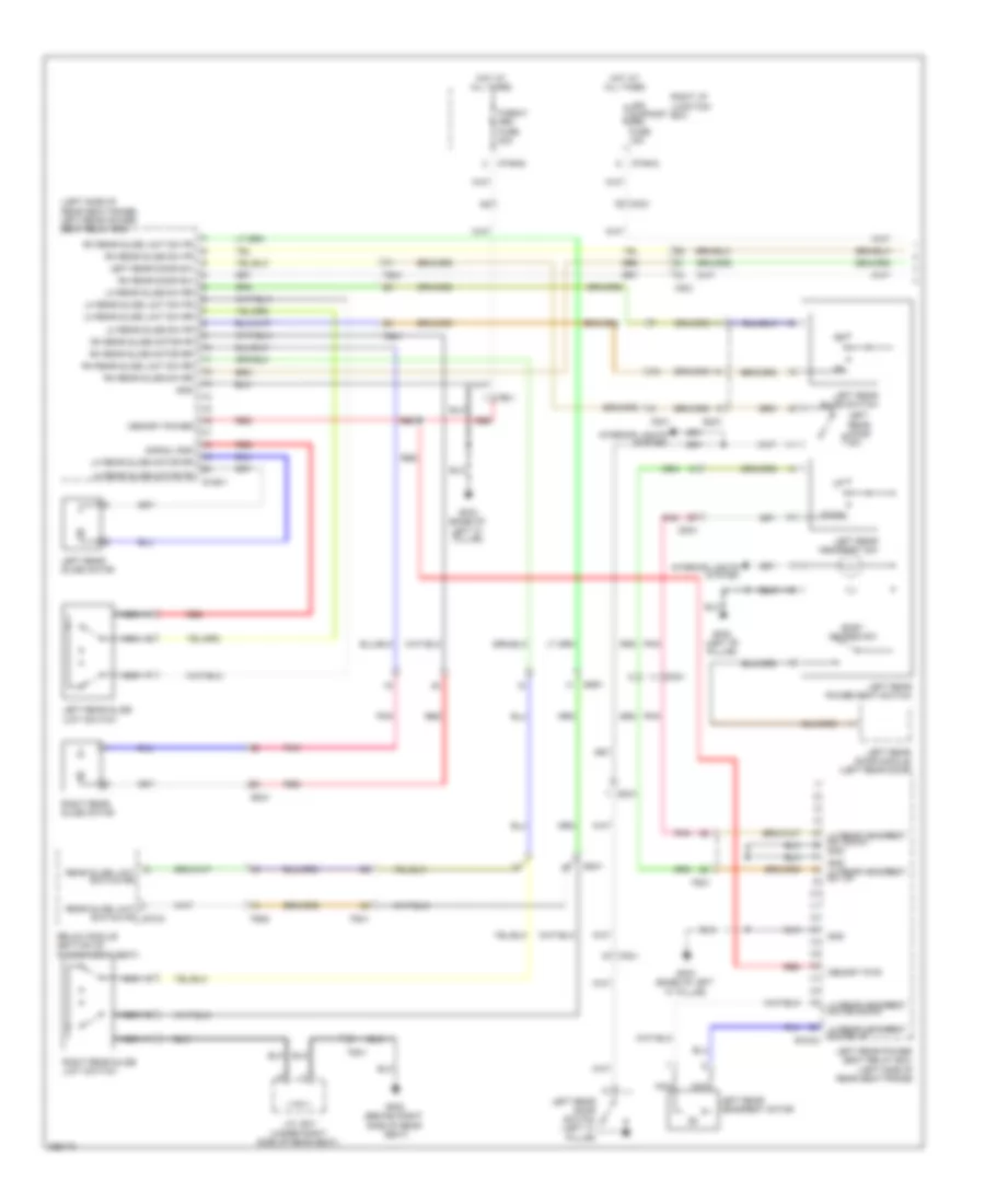 https://portal-diagnostov.com/license.html
Automotive Electricians Portal FZCO
Automotive Electricians Portal FZCO
https://portal-diagnostov.com/license.html
https://portal-diagnostov.com/license.html
Automotive Electricians Portal FZCO
Automotive Electricians Portal FZCOList of elements for Rear Power Seat Wiring Diagram, 5:5 Seat (1 of 2) for Hyundai Equus Ultimate 2012:
- (left side of rear seat frame) left rear power seat relay box
- Dd31
- Down
- Easy access sw
- Fd31
- Fs31
- Fs41
- Fs52
- Gf02 (left "b" pillar)
- Gf03 (base of left "c" pillar)
- Gf08 (behind right side of rear
- Gnd
- Gnd lh rear headrest sw up
- Hot at all times
- I/p-rha
- I/p-rhd
- Ill
- Interior lights system
- J/c js41 (under right side of rear seat)
- Left rear door module (left rear door)
- Left rear door sw
- Left rear door switch (left "c" pillar)
- Left rear headrest motor
- Left rear headrest sw
- Left rear power seat relay box (left side of rear seat frame)
- Left rear power seat switch
- Left rear slide limit switch
- Left rear slide motor
- Left rear slide switch
- Leg support (rr) fuse 15a
- Lh rear headrest motor down
- Lh rear headrest motor up s126-2
- Lh rear headrest sw down
- Lh rear slide limit sw fr
- Lh rear slide limit sw rr
- Lh rear slide motor fr
- Lh rear slide motor rr
- Lh rear slide sw fr
- Lh rear slide sw rr
- Memory power
- Memory pwr
- Mf21
- Nca
- P/seat (rr) fuse 20a
- Pnk
- Rear slide limit switch fr s70-d
- Rear slide limit switch rr
- Red
- Relax module (bottom of passenger's seat)
- Rh rear door sw
- Rh rear slide limit sw fr
- Rh rear slide limit sw rr
- Rh rear slide motor fr
- Rh rear slide motor rr
- Rh rear slide sw fr
- Rh rear slide sw rr
- Right i/p junction box
- Right rear slide limit switch
- Right rear slide motor
- S126-1
- Seat)
- Signal gnd
- Ss41
- Ss51
Rear Power Seat Wiring Diagram, 5:5 Seat (2 of 2) for Hyundai Equus Ultimate 2012
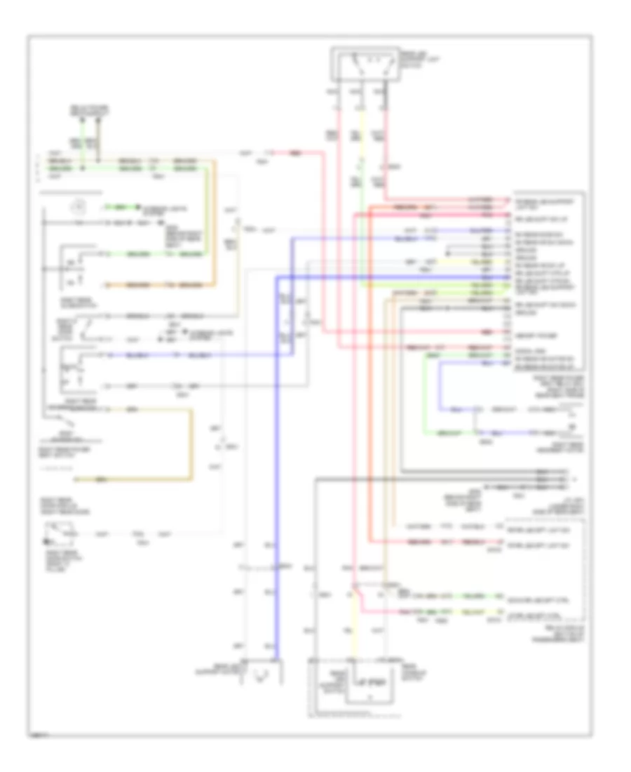 https://portal-diagnostov.com/license.html
Automotive Electricians Portal FZCO
Automotive Electricians Portal FZCO
https://portal-diagnostov.com/license.html
https://portal-diagnostov.com/license.html
Automotive Electricians Portal FZCO
Automotive Electricians Portal FZCOList of elements for Rear Power Seat Wiring Diagram, 5:5 Seat (2 of 2) for Hyundai Equus Ultimate 2012:
- Dd41
- Down
- Down rr leg spt ctrl
- Easy access sw
- Fd41
- Fr rear leg support limit sw
- Fr rr leg spt limit sw
- Fs41
- Fs52
- Gf08 (behind right side of rear seat)
- Gf09 (behind right side of rear seat)
- Ground
- Ill
- Interior lights system
- J/c js41 (under right side of rear seat)
- Memory power
- Nca
- Pnk
- Rear console switch
- Rear leg support limit switch
- Rear leg support motor
- Rear leg support switch
- Red
- Relax module (bottom of passenger's seat)
- Relax power seats circuit
- Rh rear door sw
- Rh rear hr motor dn
- Rh rear hr motor up
- Rh rear hr sw down
- Rh rear hr sw up
- Right rear door module (right rear door)
- Right rear door switch
- Right rear door switch (right "c" pillar)
- Right rear headrest motor
- Right rear headrest switch
- Right rear power seat relay box (right side of rear seat frame)
- Right rear power seat switch
- Right rear slide switch
- Rr leg supt mtr dn rr rear leg support limit sw
- Rr leg supt mtr up
- Rr leg supt sw down
- Rr leg supt sw up
- Rr rr leg spt limit sw
- S37-a
- S70-c
- S70-d
- Signal gnd
- Ss41
- Ss42
- Ss43
- Up rr leg spt ctrl
Rear Power Seat Wiring Diagram, 6:4 Seat (1 of 2) for Hyundai Equus Ultimate 2012
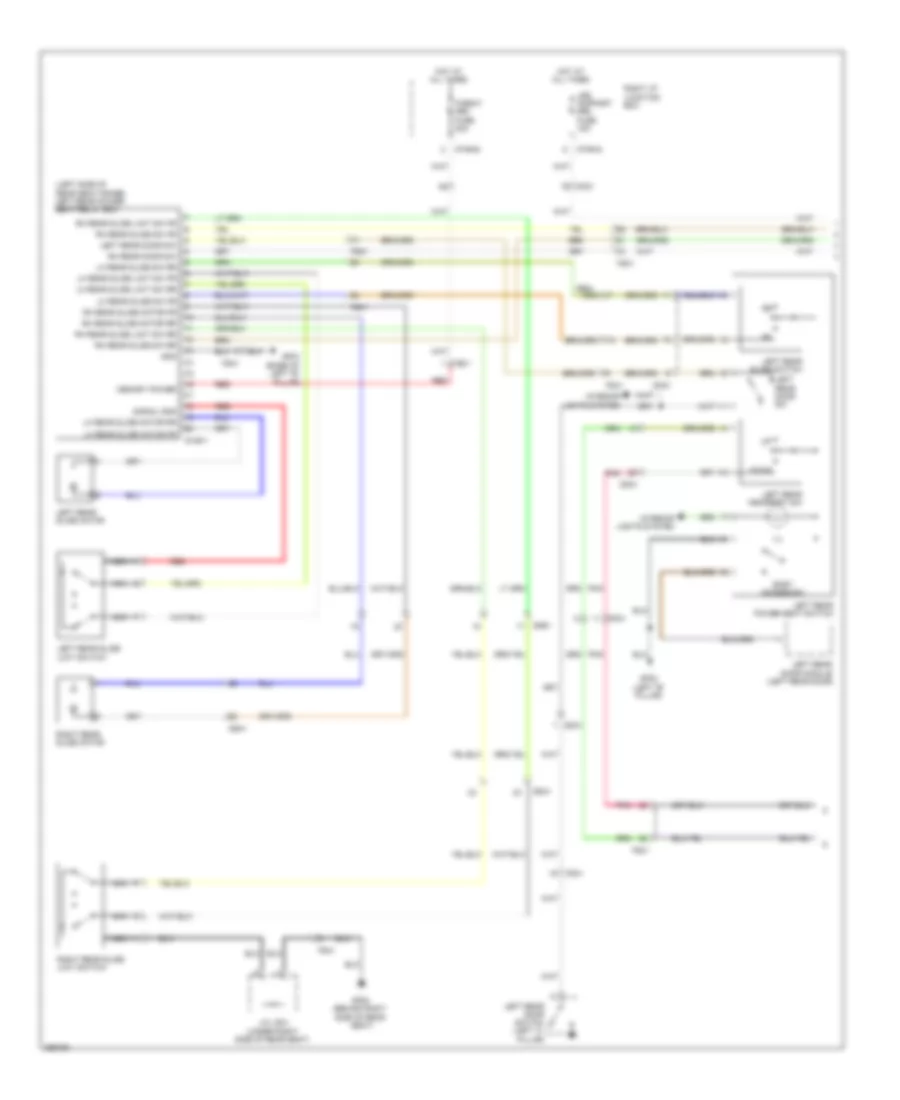 https://portal-diagnostov.com/license.html
Automotive Electricians Portal FZCO
Automotive Electricians Portal FZCO
https://portal-diagnostov.com/license.html
https://portal-diagnostov.com/license.html
Automotive Electricians Portal FZCO
Automotive Electricians Portal FZCOList of elements for Rear Power Seat Wiring Diagram, 6:4 Seat (1 of 2) for Hyundai Equus Ultimate 2012:
- (left side of rear seat frame) left rear power seat relay box
- Dd31
- Down
- Easy access sw
- Fd31
- Fs31
- Fs41
- Gf02 (left "b" pillar)
- Gf03 (base of left "b"
- Gf08 (behind right side of rear
- Gnd
- Hot at all times
- I/p-rha
- I/p-rhd
- Ill
- Interior lights system
- J/c js41 (under right side of rear seat)
- Left rear door module (left rear door)
- Left rear door sw
- Left rear door switch (left "c" pillar)
- Left rear headrest sw
- Left rear power seat switch
- Left rear slide limit switch
- Left rear slide motor
- Left rear slide switch
- Leg support (rr) fuse 15a
- Lh rear slide limit sw fr
- Lh rear slide limit sw rr
- Lh rear slide motor fr
- Lh rear slide motor rr
- Lh rear slide sw fr
- Lh rear slide sw rr
- Memory power
- Mf21
- Nca
- P/seat (rr) fuse 20a
- Pillar)
- Pnk
- Red
- Rh rear door sw
- Rh rear slide limit sw fr
- Rh rear slide limit sw rr
- Rh rear slide motor fr
- Rh rear slide motor rr
- Rh rear slide sw fr
- Rh rear slide sw rr
- Right i/p junction box
- Right rear slide limit switch
- Right rear slide motor
- S126-1
- Seat)
- Signal gnd
- Ss41
- Ss51
Rear Power Seat Wiring Diagram, 6:4 Seat (2 of 2) for Hyundai Equus Ultimate 2012
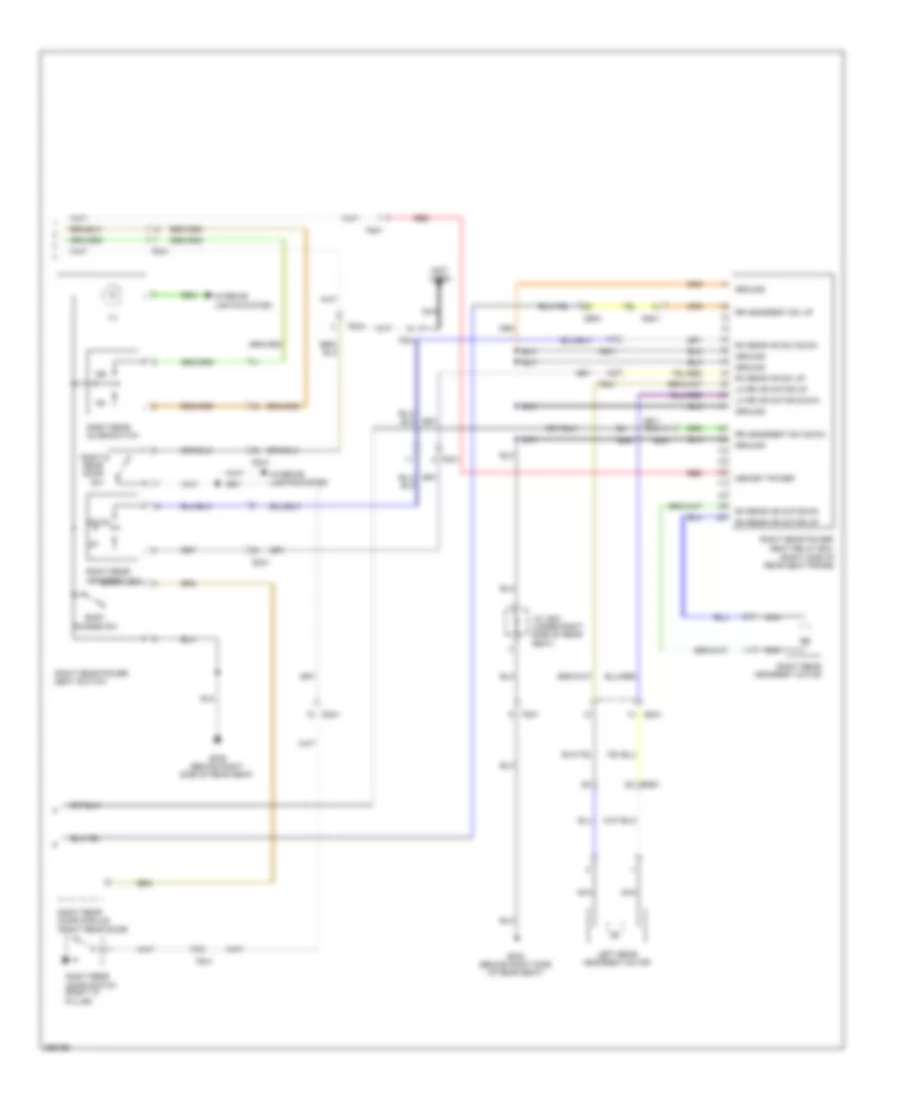 https://portal-diagnostov.com/license.html
Automotive Electricians Portal FZCO
Automotive Electricians Portal FZCO
https://portal-diagnostov.com/license.html
https://portal-diagnostov.com/license.html
Automotive Electricians Portal FZCO
Automotive Electricians Portal FZCOList of elements for Rear Power Seat Wiring Diagram, 6:4 Seat (2 of 2) for Hyundai Equus Ultimate 2012:
- (not used)
- Dd41
- Down
- Easy access sw
- Fd41
- Fs41
- Gf08 (behind right side of rear seat)
- Gf09 (behind right side of rear seat)
- Ground
- Ill
- Interior lights system
- J/c js41 (under right side of rear seat)
- Left rear headrest motor
- Lh rr hr motor down
- Lh rr hr motor up
- Memory power
- Nca
- Red
- Rh rear hr motor dn
- Rh rear hr motor up
- Rh rear hr sw down
- Rh rear hr sw up
- Right rear door module (right rear door)
- Right rear door sw
- Right rear door switch (right "c" pillar)
- Right rear headrest motor
- Right rear headrest sw
- Right rear power seat relay box (right side of rear seat frame)
- Right rear power seat switch
- Right rear slide switch
- Rr headrest sw down
- Rr headrest sw up
- Ss41
- Ss51
Rear Seat Massage Wiring Diagram for Hyundai Equus Ultimate 2012
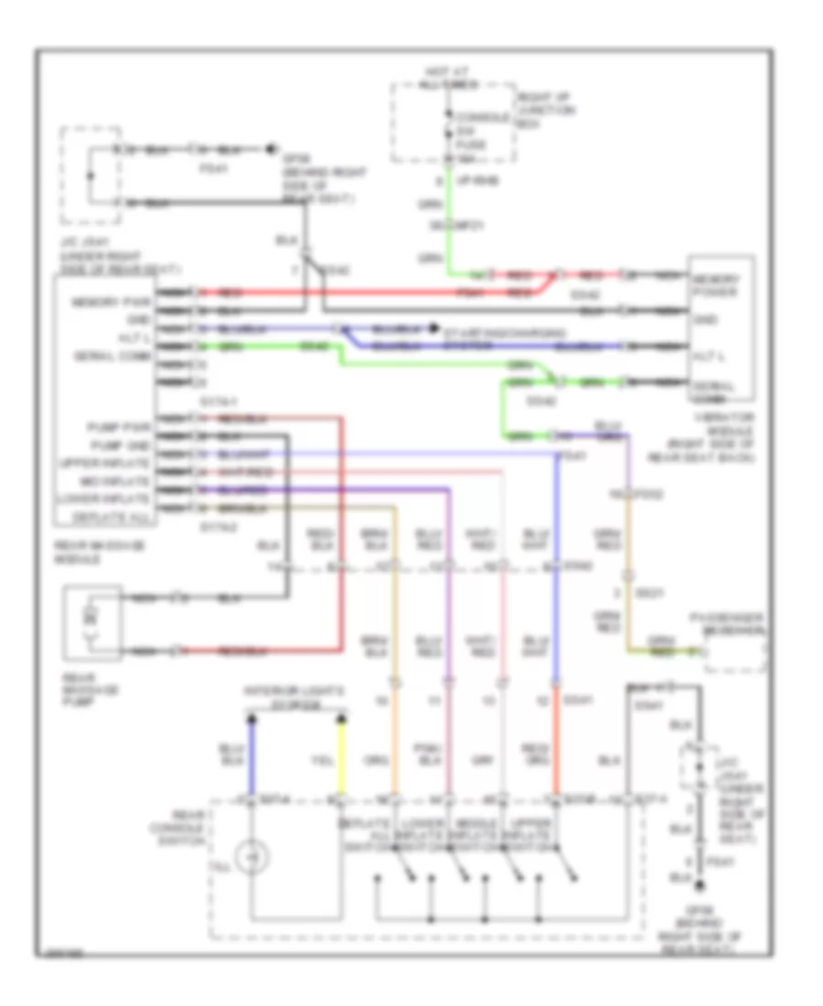 https://portal-diagnostov.com/license.html
Automotive Electricians Portal FZCO
Automotive Electricians Portal FZCO
https://portal-diagnostov.com/license.html
https://portal-diagnostov.com/license.html
Automotive Electricians Portal FZCO
Automotive Electricians Portal FZCOList of elements for Rear Seat Massage Wiring Diagram for Hyundai Equus Ultimate 2012:
- Alt l
- Console sw fuse 10a
- Deflate all switch
- Fs41
- Fs52
- Gf08 (behind right side of rear seat)
- Gnd
- Hot at all times
- I/p-rhb
- Ill
- Interior lights system
- J/c js41 (under right side of rear seat)
- Lower inflate switch
- Mf21
- Middle inflate switch
- Nca
- Nca memory power
- Nca memory pwr nca gnd nca alt l nca serial comm nca
- Nca pump pwr nca pump gnd nca upper inflate nca mid inflate nca lower inflate nca deflate all
- Nca serial comm
- Passenger receiver
- Rear console switch
- Rear massage module
- Rear massage pump
- Red
- Right i/p junction box
- S174-1
- S174-2
- S37-a
- S37-b
- Ss21
- Ss41
- Ss42
- Starting/charging system
- Upper inflate switch
- Vibrator module (right side of rear seat back)
Relax Power Seat Wiring Diagram, 5:5 Seat (1 of 2) for Hyundai Equus Ultimate 2012
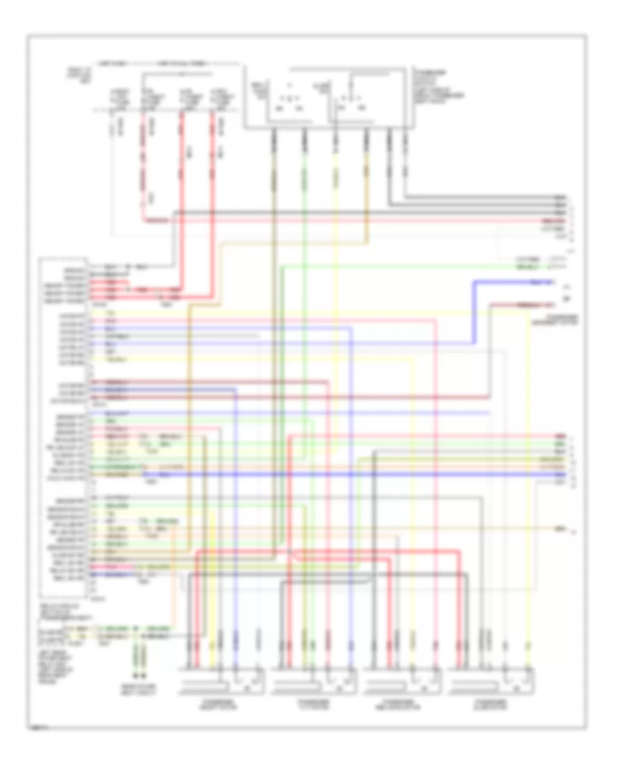 https://portal-diagnostov.com/license.html
Automotive Electricians Portal FZCO
Automotive Electricians Portal FZCO
https://portal-diagnostov.com/license.html
https://portal-diagnostov.com/license.html
Automotive Electricians Portal FZCO
Automotive Electricians Portal FZCOList of elements for Relax Power Seat Wiring Diagram, 5:5 Seat (1 of 2) for Hyundai Equus Ultimate 2012:
- (left side of front passenger seat back)
- Body unit fuse 10a
- Fd21
- Fr h/seat fuse 10a
- Fr p/seat fuse 20a
- Fr-2 p/seat fuse 15a
- Fs31
- Fs51
- Fs52
- Ground
- Hot at all times
- Hot in on
- I/p-rhb
- I/p-rhd
- I/p-rhe
- Left rear power seat relay box (left side of rear seat frame)
- Memory power
- Mf11
- Mf21
- Motor down
- Motor fr
- Motor rr
- Motor up
- Nca
- Passenger headrest motor
- Passenger height motor
- Passenger reclining motor
- Passenger slide motor
- Passenger tilt motor
- Passenger walk in switch
- Pnk
- Rear power
- Recl sw fr
- Recl sw rr
- Recl- ining sw
- Red
- Relax module (bottom of passenger's seat)
- Relax sw fr
- Relax sw rr
- Right i/p junction box
- Rr leg down
- Rr leg sup up
- Rr slide fr
- Rr slide rr
- S126-1
- S70-a
- S70-b
- S70-c
- Seat circuit
- Sensor down
- Sensor fr
- Sensor rr
- Sensor up
- Slide fr
- Slide rr
- Slide sw
- Slide sw fr
- Slide sw rr
- Walk in sw fr
Relax Power Seat Wiring Diagram, 5:5 Seat (2 of 2) for Hyundai Equus Ultimate 2012
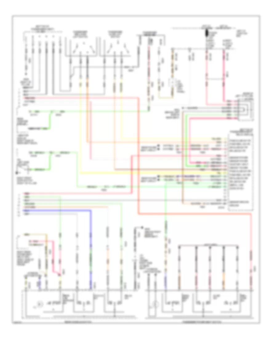 https://portal-diagnostov.com/license.html
Automotive Electricians Portal FZCO
Automotive Electricians Portal FZCO
https://portal-diagnostov.com/license.html
https://portal-diagnostov.com/license.html
Automotive Electricians Portal FZCO
Automotive Electricians Portal FZCOList of elements for Relax Power Seat Wiring Diagram, 5:5 Seat (2 of 2) for Hyundai Equus Ultimate 2012:
- (base of left "c" pillar)
- (bottom of
- (bottom of passenger's seat) relax module
- (not used)
- Body unit-1 fuse 10a
- Body unit-2 fuse 10a
- Comm serial
- Dd21
- Door op sw
- Down
- Fd21
- Fs41
- Fs51
- Fs52
- Gf04 (behind left side of
- Gf06 (right "b" pillar)
- Gf08 (behind right side of rear seat)
- Ground
- Head- rest sw
- Hot at all times
- Hot in on or start
- I/p-lha
- I/p-lhc
- I/p-lhf
- I/p-lhg
- Ill
- Interior lights system
- Ipm (left side of dash)
- J/c jf01
- J/c jf03 (left kick panel)
- J/c js21
- J/c js41 (under right side of rear seat)
- Left i/p junction box
- M40-b
- Memory power
- Mf11
- Mf21
- Nca
- On in
- On/start input
- P/conn fuse 30a
- Pass recl sw fr
- Pass recl sw rr
- Pass slide sw fr
- Pass slide sw rr
- Passenger
- Passenger power seat switch
- Passenger reclining limit switch
- Passenger slide limit switch
- Passenger's seat)
- Pnk
- Rear console switch
- Rear leg support sw
- Rear massage module
- Rear power
- Rear seat)
- Receiver
- Recl- ining sw
- Red
- Relax sw
- Right front door switch (right "b" pillar)
- Right rear power seat relay box (right side of rear seat frame)
- Rr leg sw fr
- Rr leg sw rr
- Rr slide sw fr
- Rr slide sw rr
- S174-1
- S37-a
- S37-b
- S70-d
- Seat circuit
- Sensor ground
- Sensor power
- Serial line
- Slide sw
- Ss21
- Ss41
- Ss42
- Vibrator module (right side of rear seat back)
- Walk in sw
Relax Power Seat Wiring Diagram, 6:4 Seat (1 of 2) for Hyundai Equus Ultimate 2012
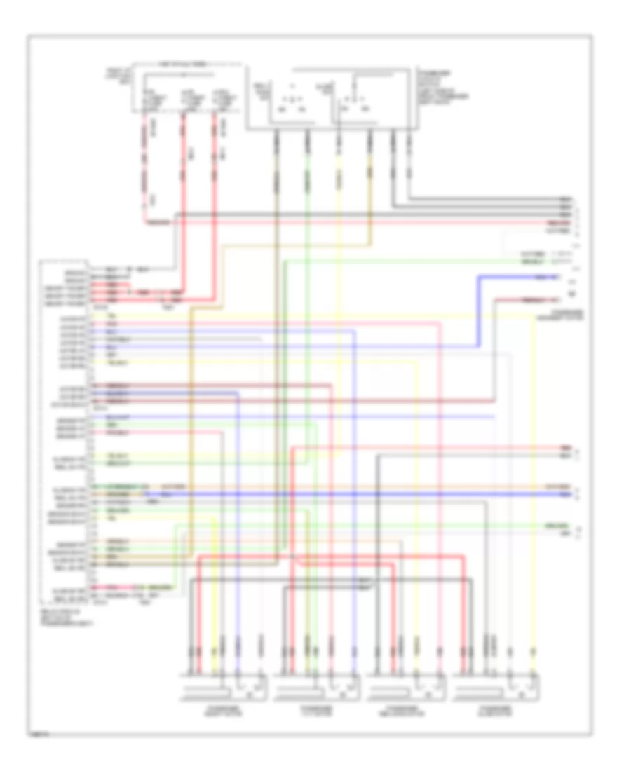 https://portal-diagnostov.com/license.html
Automotive Electricians Portal FZCO
Automotive Electricians Portal FZCO
https://portal-diagnostov.com/license.html
https://portal-diagnostov.com/license.html
Automotive Electricians Portal FZCO
Automotive Electricians Portal FZCOList of elements for Relax Power Seat Wiring Diagram, 6:4 Seat (1 of 2) for Hyundai Equus Ultimate 2012:
- (left side of front passenger seat back)
- Fd21
- Fr h/seat fuse 10a
- Fr p/seat fuse 20a
- Fr-2 p/seat fuse 15a
- Fs51
- Ground
- Hot at all times
- I/p-rhb
- I/p-rhe
- Memory power
- Mf11
- Mf21
- Motor down
- Motor fr
- Motor rr
- Motor up
- Nca
- Passenger headrest motor
- Passenger height motor
- Passenger reclining motor
- Passenger slide motor
- Passenger tilt motor
- Passenger walk in switch
- Pnk
- Recl sw fr
- Recl sw rr
- Recl- ining sw
- Red
- Relax module (bottom of passenger's seat)
- Right i/p junction box
- S70-a
- S70-b
- S70-c
- Sensor down
- Sensor fr
- Sensor rr
- Sensor up
- Slide sw
- Slide sw fr
- Slide sw rr
Relax Power Seat Wiring Diagram, 6:4 Seat (2 of 2) for Hyundai Equus Ultimate 2012
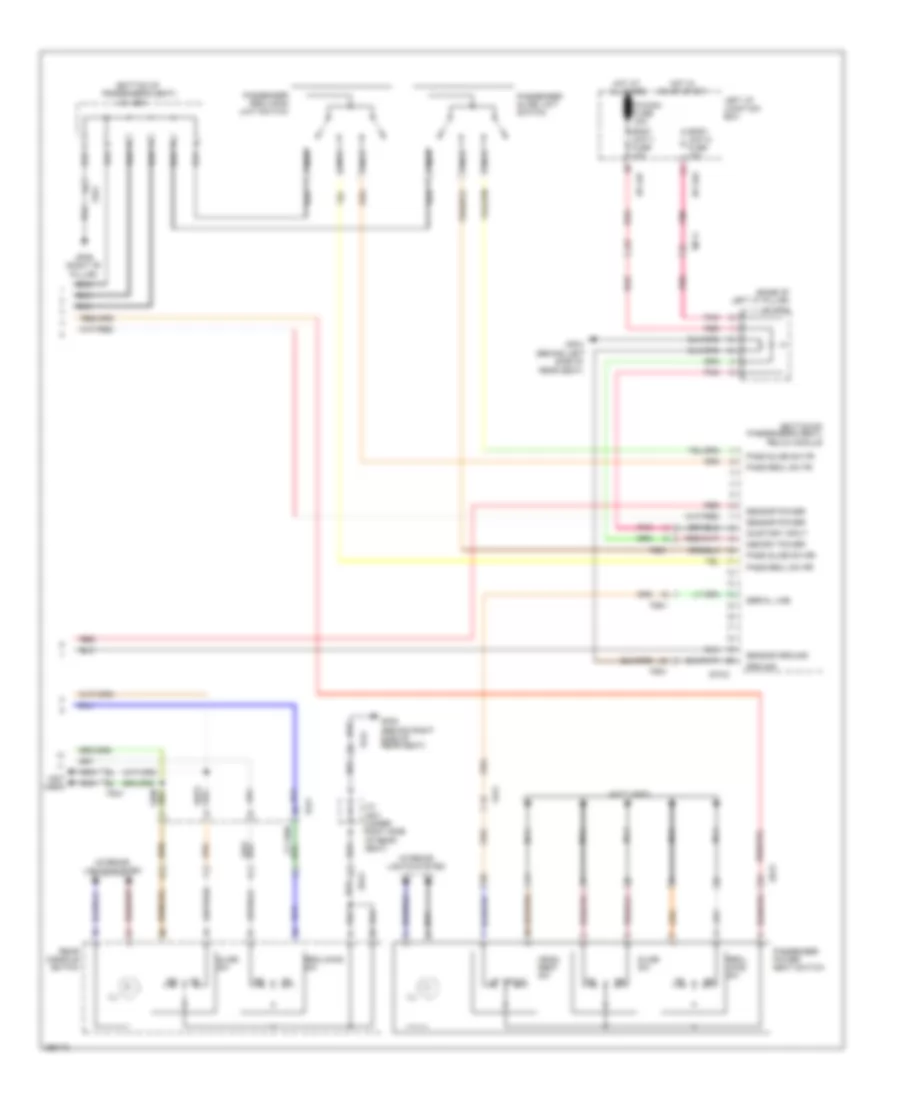 https://portal-diagnostov.com/license.html
Automotive Electricians Portal FZCO
Automotive Electricians Portal FZCO
https://portal-diagnostov.com/license.html
https://portal-diagnostov.com/license.html
Automotive Electricians Portal FZCO
Automotive Electricians Portal FZCOList of elements for Relax Power Seat Wiring Diagram, 6:4 Seat (2 of 2) for Hyundai Equus Ultimate 2012:
- (base of left "c" pillar)
- (bottom of
- (bottom of passenger's seat) relax module
- (not used)
- Body unit-1 fuse 10a
- Body unit-2 fuse 10a
- Dd21
- Down
- Fd21
- Fs41
- Fs51
- Gf04 (behind left side of
- Gf06 (right "b" pillar)
- Gf08 (behind right side of rear seat)
- Ground
- Head- rest sw
- Hot at all times
- Hot in on or start
- I/p-lhf
- I/p-lhg
- Ill
- Interior lights system
- J/c jf01
- J/c js21
- J/c js41 (under right side of rear seat)
- Left i/p junction box
- Memory power
- Mf11
- Nca
- On/start input
- P/conn fuse 30a
- Pass recl sw fr
- Pass recl sw rr
- Pass slide sw fr
- Pass slide sw rr
- Passenger power seat switch
- Passenger reclining limit switch
- Passenger slide limit switch
- Passenger's seat)
- Pnk
- Rear console switch
- Rear seat)
- Recl- ining sw
- Reclining sw
- Red
- S70-d
- Sensor ground
- Sensor power
- Serial line
- Slide sw
- Ss41
POWER TOP/SUNROOF
Power Top/Sunroof Wiring Diagram for Hyundai Equus Ultimate 2012
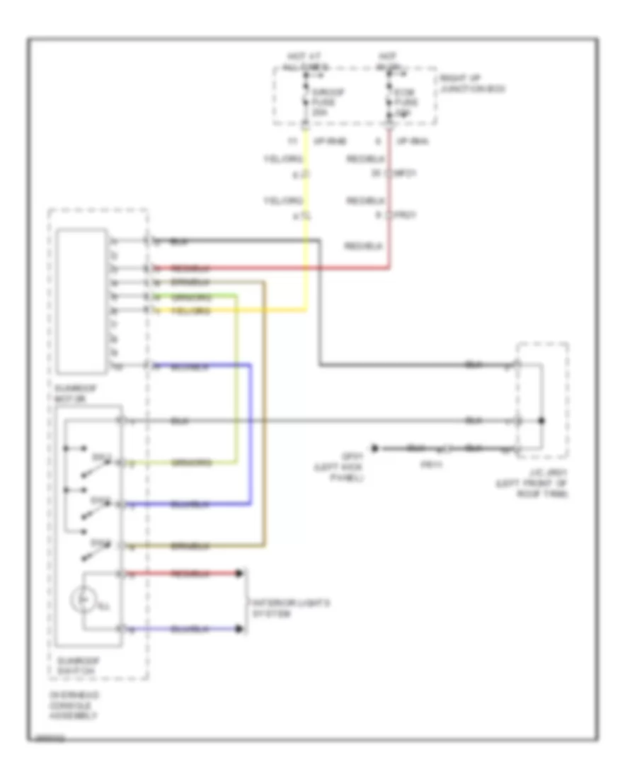 https://portal-diagnostov.com/license.html
Automotive Electricians Portal FZCO
Automotive Electricians Portal FZCO
https://portal-diagnostov.com/license.html
https://portal-diagnostov.com/license.html
Automotive Electricians Portal FZCO
Automotive Electricians Portal FZCOList of elements for Power Top/Sunroof Wiring Diagram for Hyundai Equus Ultimate 2012:
- Ecm fuse 10a
- Fr11
- Fr21
- Gf01 (left kick panel)
- Hot at all times
- Hot in on
- I/p-rha
- I/p-rhb
- Ill
- Interior lights system
- J/c jr01 (left front of roof trim)
- Mf21
- Overhead console assembly
- Right i/p junction box
- S/roof fuse 20a
- Sunroof motor
- Sunroof switch
- Sw1
- Sw2
- Sw3
POWER WINDOWS
Power Windows Wiring Diagram (1 of 2) for Hyundai Equus Ultimate 2012
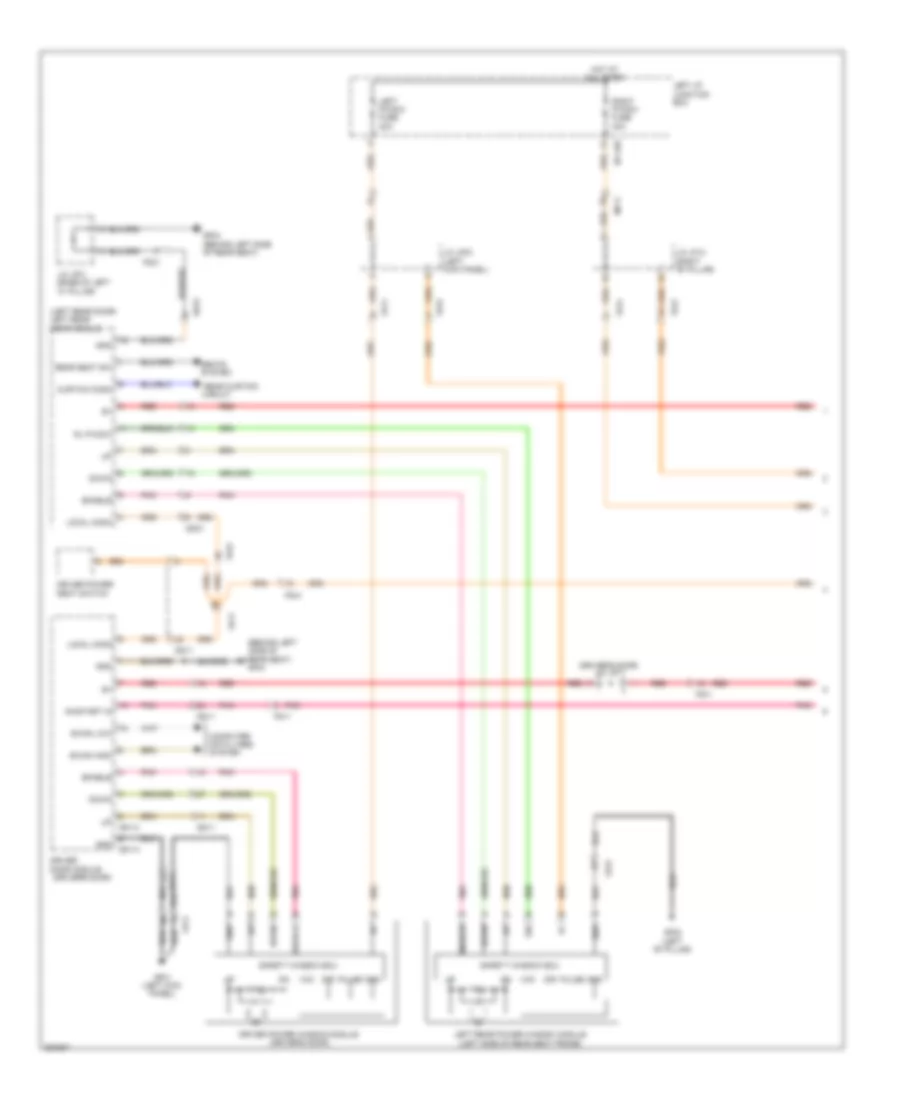 https://portal-diagnostov.com/license.html
Automotive Electricians Portal FZCO
Automotive Electricians Portal FZCO
https://portal-diagnostov.com/license.html
https://portal-diagnostov.com/license.html
Automotive Electricians Portal FZCO
Automotive Electricians Portal FZCOList of elements for Power Windows Wiring Diagram (1 of 2) for Hyundai Equus Ultimate 2012:
- (behind left
- (driver's door)
- (driver's door) j/c jd11
- (left rear door) left rear door module
- (left side of rear seat frame)
- B-can high
- B-can low
- Circuit
- Computer data lines system
- Curtain comm
- D51-a
- D51-c
- Dd11
- Dd31
- Dir
- Down
- Driver door module
- Driver power seat switch
- Driver power window module (driver's door)
- Enable
- Fd11
- Fd21
- Fd31
- Fd41
- Gf01 (left kick panel)
- Gf02 (left "b" pillar)
- Gf04
- Gf04 (behind left side of rear seat)
- Gnd
- Hot at all times
- I/p-lhd
- J/c jf01 (base of left "c" pillar)
- J/c jf03 (left kick panel)
- J/c jf13 (right "b" pillar)
- Left i/p junction box
- Left p/wdw fuse 30a
- Left rear power window module
- Local comm
- Mf11
- On/start in
- Pnk
- Pulse
- Rear curtain
- Rear seat sw
- Rear seat)
- Red
- Right p/wdw fuse 30a
- Rl p/wdw
- Safety window ecu
- Seats
- Side of
- Sig
- System
- Vcc
Power Windows Wiring Diagram (2 of 2) for Hyundai Equus Ultimate 2012
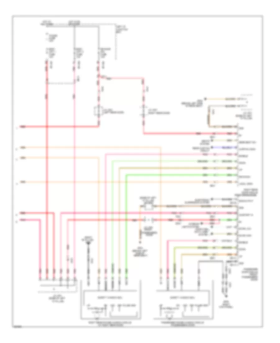 https://portal-diagnostov.com/license.html
Automotive Electricians Portal FZCO
Automotive Electricians Portal FZCO
https://portal-diagnostov.com/license.html
https://portal-diagnostov.com/license.html
Automotive Electricians Portal FZCO
Automotive Electricians Portal FZCOList of elements for Power Windows Wiring Diagram (2 of 2) for Hyundai Equus Ultimate 2012:
- "c" pillar)
- "c" pillar) j/c jf01
- (base of left
- (right "b" pillar) gf06
- (right rear door)
- B-can high
- B-can low
- Body unit 1 fuse 10a
- Body unit 2 fuse 10a
- Computer data lines system
- Curtain comm
- D61-a
- D61-b
- D61-c
- Dd21
- Dd41
- Dir
- Down
- Ecs output
- Electronic suspension system
- Enable
- Fd21
- Fd31
- Fd41
- Gf04 (behind left side of rear seat)
- Gf05 (right kick panel)
- Gnd
- Hot at all times
- Hot in on or start
- I/p-lhc
- I/p-lhf
- I/p-lhg
- Interior lights system
- J/c jd21 (front
- J/c jd31 (left rear door)
- J/c jd41
- J/c jf01 (base of left
- J/c jf01 (base of left "c" pillar)
- Left i/p junction box
- Local comm
- Mf11
- On/start in
- P/conn fuse 30a
- Passenger door module (front passenger's door)
- Passenger power window module (passenger's door)
- Passenger's door)
- Pnk
- Pulse
- Rear curtain circuit
- Rear seat sw
- Red
- Right rear door module
- Right rear power window module (at right rear door)
- Rr door mdl fuse 10a
- Rr p/wdw
- Safety window ecu
- Seats system
- Sig
- Vcc
Rear Curtain Wiring Diagram for Hyundai Equus Ultimate 2012
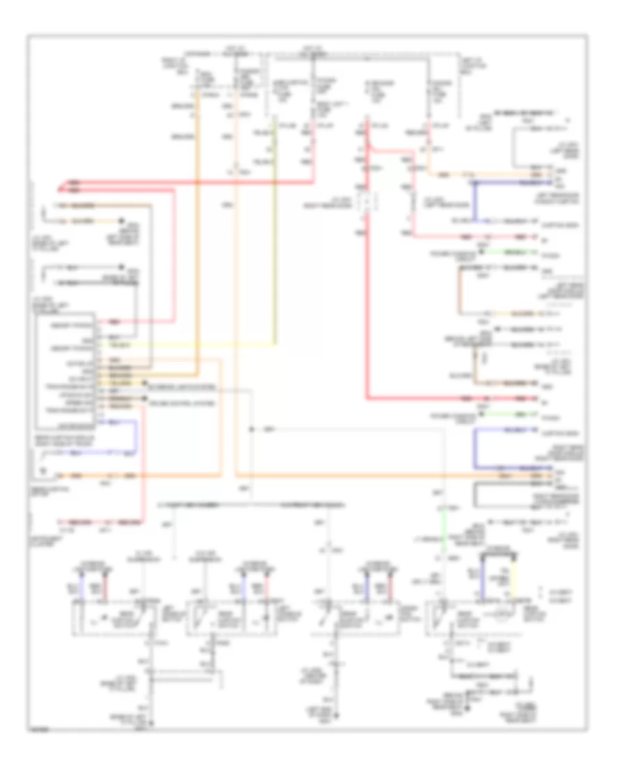 https://portal-diagnostov.com/license.html
Automotive Electricians Portal FZCO
Automotive Electricians Portal FZCO
https://portal-diagnostov.com/license.html
https://portal-diagnostov.com/license.html
Automotive Electricians Portal FZCO
Automotive Electricians Portal FZCOList of elements for Rear Curtain Wiring Diagram for Hyundai Equus Ultimate 2012:
- "c" pillar)
- (base of left
- (base of left "c" pillar) gf03
- (behind right side of rear seat) gf08
- (center
- (left end of dash) gm01
- (right rear door)
- 5:5 seat
- 5:5 seat 6:4 seat
- 6:4 seat
- B+ gnd
- B+ sig
- Body unit 1 fuse 10a
- Box
- Crash pad switch
- Cruise control system
- Curtain comm
- Curtain switch
- Dd31
- Dd41
- Ecm fuse 10a
- Exterior lights system
- F15-a
- F15-c
- F15-c f15-c
- Fd31
- Fd41
- Ff01
- Fs31
- Fs41
- Gf02 (left "b" pillar)
- Gf03 (base of left "c" pillar)
- Gf04 (behind left side of rear seat)
- Gf09 (behind right side of rear seat)
- Gnd
- Hot at all times
- Hot in on
- I/p-lhc
- I/p-lhe
- I/p-lhf
- I/p-rha
- I/p-rhe
- Ill
- Instrument cluster
- Interior lights system
- J/c jd31 (left rear door)
- J/c jd41
- J/c jd41 (right rear door)
- J/c jf01 (base of left "c" pillar)
- J/c jf02
- J/c jf02 (base of left "c" pillar)
- J/c jm05
- J/c js41 (under right side of rear seat)
- Left console switch
- Left i/p junction box
- Left rear door module (left rear door)
- Left rear door window curtain
- M11-b
- Memory pwr b+
- Mf11
- Mf21
- Motor
- Motor down
- Motor up
- Of dash)
- On input
- P/conn fuse 30a
- P/ddor (rr) fuse 15a
- P/door (rl) fuse 15a
- P/wdw
- Power windows circuit
- Rear
- Rear curtain
- Rear curtain module (right side of trunk)
- Rear curtain switch
- Red
- Right i/p junction
- Right rear door module (right rear door)
- Right rear door window curtain
- Rr curtain mtr fuse 10a
- Rr door mdl fuse 10a
- S37-a
- S37-b s37-b
- Sig
- Speed sig
- Ss41
- Ss51
- Tran range sw p
- Tran range sw r
- Up/down sw
- W/ air suspension
- W/ front view camera
- W/o air suspension
- W/o front view camera
RADIO
Radio Wiring Diagram (1 of 4) for Hyundai Equus Ultimate 2012
 https://portal-diagnostov.com/license.html
Automotive Electricians Portal FZCO
Automotive Electricians Portal FZCO
https://portal-diagnostov.com/license.html
https://portal-diagnostov.com/license.html
Automotive Electricians Portal FZCO
Automotive Electricians Portal FZCOList of elements for Radio Wiring Diagram (1 of 4) for Hyundai Equus Ultimate 2012:
- (center of dash)
- (left center of dash) gmo3
- (right "c" pillar) gf07
- 6:4 seats
- A/v & navigation head unit
- Acc/on in
- Audio (b+) fuse 15a
- Audio (ig1) fuse 10a
- Aux gnd
- Aux l
- Aux r
- Body k-line
- Camera module (right center of dash)
- Computer data lines system
- Dis switch
- Em41
- Esc module (left front of engine compt)
- Fr11
- Fs31
- Gmo1 (left end of dash)
- Gnd
- Hot at all times
- Hot in on or start
- I/p-lhc
- I/p-lhg
- Ill (+)
- Ill (-)
- Interior lights system
- J/c jm01 (center of dash)
- J/c jm05
- J/c jr03 (left front of room trim)
- Left i/p junction box
- M-can hi
- M-can high
- M-can low
- Memory pwr
- Mf11
- Mf21
- Mic
- Mic (+)
- Mic (-)
- Mm11
- Most e wake up
- Most rx
- Nca
- On/start in
- P/conn fuse 30a
- Pnk
- Power distri- bution system
- Pwr
- Rear audio switch
- Red
- Reset
- Shield gnd
- Speed sig
- Ss51
- To av jbl amp (diagram 4 of 4)
- Video gnd
- Video in
- Video sig
- Wake up
Radio Wiring Diagram (2 of 4) for Hyundai Equus Ultimate 2012
 https://portal-diagnostov.com/license.html
Automotive Electricians Portal FZCO
Automotive Electricians Portal FZCO
https://portal-diagnostov.com/license.html
https://portal-diagnostov.com/license.html
Automotive Electricians Portal FZCO
Automotive Electricians Portal FZCOList of elements for Radio Wiring Diagram (2 of 4) for Hyundai Equus Ultimate 2012:
- (left end of dash) gm01
- A/v & navigation head unit
- Acc/on in
- Aux detect
- Aux gnd
- Aux l
- Aux l in
- Aux r
- Aux r in
- Aux ref
- Computer data lines system
- Dash)
- Data
- Front monitor
- Gmo3 (left center
- Gmo6 (left end of
- Gnd
- Ill (+)
- Interior lights system
- J/c jm01 (center of dash)
- J/c jm05 (center of dash)
- J/c jm21 (rear of center console)
- M-can high
- M-can low
- M31
- M45-a
- M45-b
- Media jack module
- Media module (right center of dash)
- Memory pwr
- Mf11
- Mm11
- Nca
- Of dash)
- Pnk
- Rear monitor
- Red
- Tx0+
- Tx0-
- Tx1+
- Tx1-
- Tx2+
- Tx2-
- Txclk+
- Txclk-
- Usb 5v
- Usb d+/ipod tx
- Usb d-/ipod rx
- Usb gnd
- Usb/ipod 5v
- Usb/ipod gnd
- Video gnd
- Video in
Radio Wiring Diagram (3 of 4) for Hyundai Equus Ultimate 2012
 https://portal-diagnostov.com/license.html
Automotive Electricians Portal FZCO
Automotive Electricians Portal FZCO
https://portal-diagnostov.com/license.html
https://portal-diagnostov.com/license.html
Automotive Electricians Portal FZCO
Automotive Electricians Portal FZCOList of elements for Radio Wiring Diagram (3 of 4) for Hyundai Equus Ultimate 2012:
- (if equip- ped)
- 12v
- B-can
- Can ic
- Clock spring
- Computer data lines system
- Disp
- E/r fuse & relay box (left side of engine compt)
- E/r junction box (right rear of engine compt)
- E/r-e1a
- E/r-e1b
- Em21
- Em31
- Engine compt)
- Fam
- Fam power-1 fuse 40a
- Fam power-2 fuse 40a
- Fam-a
- Fam-b
- Fam-c
- Ge04 (lower right rear of
- Gm01 (left end of dash)
- Gnd
- H/f cancel
- H/free
- High
- Hot at all times
- Ill
- Ims fuse 10a
- Ims relay
- Ims relay ctrl
- J/c jm03 (right end of dash)
- Ldws
- Left steering remote control switch (down)
- Low
- M92-a
- M92-b
- Mcu
- Memory pwr
- Memory systems
- Mf21
- Mode
- Multifunction switch (remote control)
- Nca
- Pnk
- Red
- Right steering remote control switch (down)
- Right steering remote control switch (up)
- Scc
- Seek (+)
- Seek (-)
- Steering wheel
- Trip
- Voice
- Vol (+)
- Vol (-)
Radio Wiring Diagram (4 of 4) for Hyundai Equus Ultimate 2012
 https://portal-diagnostov.com/license.html
Automotive Electricians Portal FZCO
Automotive Electricians Portal FZCO
https://portal-diagnostov.com/license.html
https://portal-diagnostov.com/license.html
Automotive Electricians Portal FZCO
Automotive Electricians Portal FZCOList of elements for Radio Wiring Diagram (4 of 4) for Hyundai Equus Ultimate 2012:
- (+)
- (-)
- (not used)
- Amp 1 fuse 40a
- Audio (acc) fuse 10a
- Av jbl amp (right side of trunk)
- Center speaker
- Dd11
- Dd21
- Dd31
- Dd41
- Deck lh (+)
- Deck lh (-)
- Deck rh (+)
- Deck rh (-)
- E/r fuse & relay box (left side of engine compt)
- Ef11
- F07
- F08-a
- F08-b
- Fd11
- Fd21
- Fd31
- Fd41
- Ff01
- Fl (+)
- Fl (-)
- Fr (+)
- Fr (-)
- From a/v & navigation head unit a (diagram 1 of 4)
- Gf07 (right "c" pillar)
- Glass antenna
- Gnd
- Hot at all times
- Hot in acc or on
- I/p-rhd
- I/p-rhe
- J/c jf11 (base of right "c" pillar)
- Left deck speaker
- Left front door middle speaker
- Left front door speaker
- Left front tweeter speaker
- Left rear door middle speaker
- Left rear door speaker
- Left rear tweeter speaker
- Memory pwr
- Mf21
- Most e wake up
- Most tx
- Nca
- Pnk
- Radio tuner
- Red
- Right deck speaker
- Right front door middle speaker
- Right front door speaker
- Right front tweeter speaker
- Right i/p junction box
- Right rear door middle speaker
- Right rear door speaker
- Right rear tweeter speaker
- Rl (+)
- Rl (-)
- Rr (+)
- Rr (-)
- S/woofer 1 (+)
- S/woofer 1 (-)
- S/woofer 2 (+)
- S/woofer 2 (-)
- Sub woofer
STARTING/CHARGING
Charging Wiring Diagram for Hyundai Equus Ultimate 2012
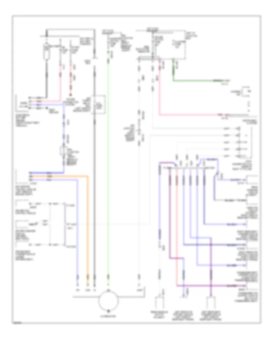 https://portal-diagnostov.com/license.html
Automotive Electricians Portal FZCO
Automotive Electricians Portal FZCO
https://portal-diagnostov.com/license.html
https://portal-diagnostov.com/license.html
Automotive Electricians Portal FZCO
Automotive Electricians Portal FZCOList of elements for Charging Wiring Diagram for Hyundai Equus Ultimate 2012:
- (5:5 seat)
- (right side of rear seat back)
- Alt fuse 200a
- Alternator
- Battery
- Battery & battery fuse box
- Body ground
- Box
- Bs fuse 10a
- Charge ind
- Cluster fuse 10a
- Com
- Cruise switch fuse 10a
- Ctg-k
- Distribution
- Driver ccs control module
- Driver massage module (driver's seat back)
- Driver seat warmer module (under driver's seat)
- E/r fuse & relay box (left side of engine compt)
- E/r junction box (right rear of engine compt)
- E/r junction box (right rear of engine compt) e/r-ca
- E/r-ca
- E/r-cb
- E/r-e2a
- Ecm (engine control module) (left rear of engine compt)
- Ee01
- Ef01
- Ef21
- Em21
- Ff11
- Fs11
- Fs31
- Fs41
- Fs51
- Hot in on or start
- I/p-lhd
- I/p-lhe
- Ig1
- Inhibitor switch fuse 15a
- Instrument cluster
- Joint
- Joint connector jf12 (base of right "c" pillar)
- Lamp
- Left i/p junction box
- Left rear ccs control module (left side of rear seat frame)
- Left rear seat warmer module (left side of rear seat frame)
- Lin line
- M11-a
- M11-b
- Mf21
- Nca
- Passenger ccs control module (bottom of passenger's seat)
- Passenger seat warmer module (under front passenger's seat)
- Pnk
- Power
- Pre- excitation resistor
- Rear console switch (5:5 seat)
- Rear massage module
- Red
- Right rear ccs control module (right side of rear seat frame)
- Right rear seat warmer module (right side of rear seat frame)
- S06-b
- S106-b
- S146-b
- S174-1
- S37-a
- S46-b
- Snsr+
- Ss42
- Ss51
- Start fuse 50a
- System
- Terminal)
- Vibrator module
- W/ ccs
- W/o ccs
4.6L
4.6L, Starting Wiring Diagram for Hyundai Equus Ultimate 2012
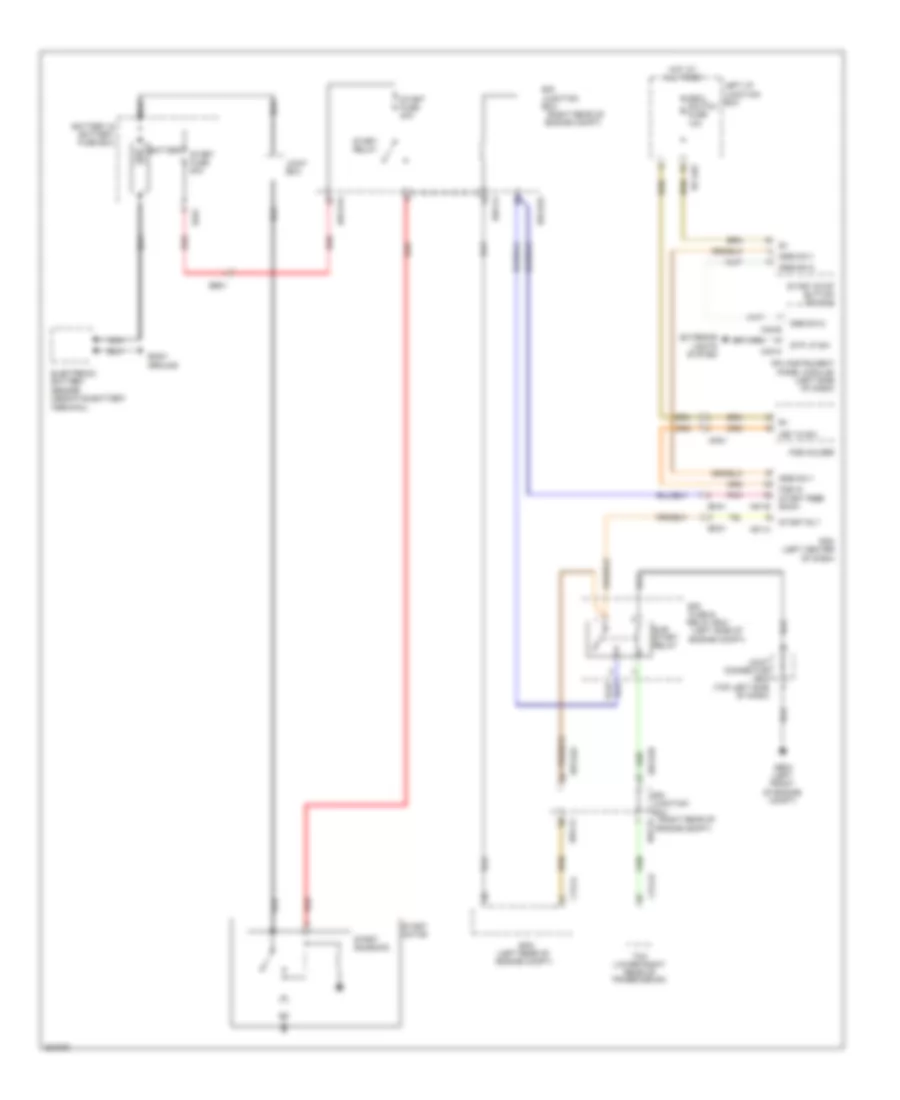 https://portal-diagnostov.com/license.html
Automotive Electricians Portal FZCO
Automotive Electricians Portal FZCO
https://portal-diagnostov.com/license.html
https://portal-diagnostov.com/license.html
Automotive Electricians Portal FZCO
Automotive Electricians Portal FZCOList of elements for 4.6L, Starting Wiring Diagram for Hyundai Equus Ultimate 2012:
- (left rear of engine compt)
- (left side of engine compt)
- (right rear of
- Battery
- Battery & battery fuse box
- Body ground
- Ctg-k
- Ctg-zf
- E/r
- E/r junction box
- E/r-ca
- E/r-cb
- E/r-e1a
- E/r-e2a
- E/r-e2b
- Ecm
- Ee01
- Ef01
- Em31
- Em41
- Engine compt)
- Escl switch fuse 10a
- Exterior lights system
- Fob holder
- Fob in start feed back
- Fuse &
- Ge03 (left front of engine compt)
- Hot at all times
- I/p-lhe
- Ipm (instrument panel module) (left side of dash)
- Joint box
- Joint connector je02 (top left side of dash)
- Key in sw
- Left i/p junction box
- M40-a
- M40-b
- M51-a
- M51-b
- Mm01
- Nca
- Pdm (left center of dash)
- Pnk
- Red
- Relay box
- Ssb sw-1
- Ssb sw-2
- Start fuse 30a
- Start fuse 50a
- Start motor
- Start relay
- Start rly
- Start solenoid
- Start stop button switch
- Stp lp sw
- Sub start relay
- Tcm (lower right rear of transmission)
- Terminal)
5.0L
5.0L, Starting Wiring Diagram for Hyundai Equus Ultimate 2012
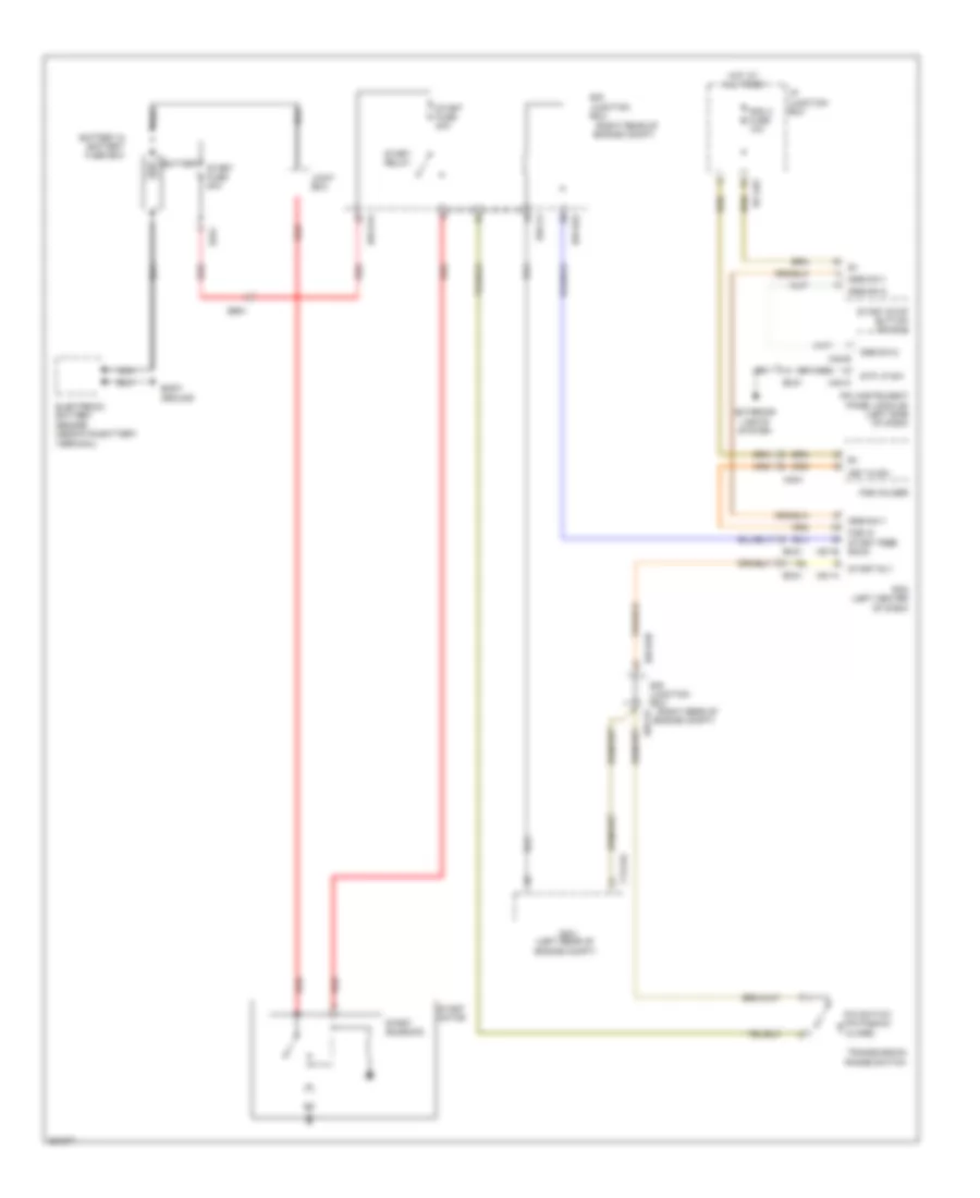 https://portal-diagnostov.com/license.html
Automotive Electricians Portal FZCO
Automotive Electricians Portal FZCO
https://portal-diagnostov.com/license.html
https://portal-diagnostov.com/license.html
Automotive Electricians Portal FZCO
Automotive Electricians Portal FZCOList of elements for 5.0L, Starting Wiring Diagram for Hyundai Equus Ultimate 2012:
- (left rear of engine compt)
- (right rear of
- :close)
- Battery
- Battery & battery fuse box
- Body ground
- Ctg-kg
- E/r junction box
- E/r-ca
- E/r-cb
- E/r-e1a
- E/r-e2a
- E/r-e2b
- Ecm
- Ee01
- Ef01
- Em31
- Em41
- Engine compt)
- Exterior
- Fob holder
- Fob in start feed back
- Hot at all times
- I/p junction box
- I/p-lhe
- Ipm (instrument panel module) (left side of dash)
- Joint box
- Key in sw
- Lights system
- M40-a
- M40-b
- M51-a
- M51-b
- Mm01
- Nca
- P/n switch (p/n position
- Pdm (left center of dash)
- Pdm 3 fuse 10a
- Red
- Ssb sw-1
- Ssb sw-2
- Start fuse 30a
- Start fuse 50a
- Start motor
- Start relay
- Start rly
- Start solenoid
- Start stop button switch
- Stp lp sw
- Terminal)
- Transmission range switch
SUPPLEMENTAL RESTRAINTS
Air Bag Wiring Diagram (1 of 3) for Hyundai Equus Ultimate 2012
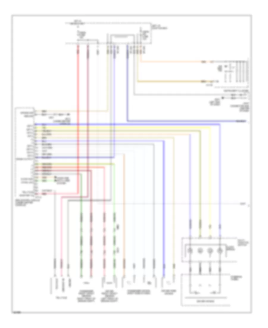 https://portal-diagnostov.com/license.html
Automotive Electricians Portal FZCO
Automotive Electricians Portal FZCO
https://portal-diagnostov.com/license.html
https://portal-diagnostov.com/license.html
Automotive Electricians Portal FZCO
Automotive Electricians Portal FZCOList of elements for Air Bag Wiring Diagram (1 of 3) for Hyundai Equus Ultimate 2012:
- (+)
- (-)
- 1st(+)
- 1st(-)
- 2st(+)
- 2st(-)
- A/bag fuse 15a
- A/bag ind fuse 10a
- Air bag ind
- C-can high
- C-can low
- Clock spring
- Computer data lines system
- Crash output
- Driver air bag
- Driver front impact sensor (left front of engine compt)
- Driver knee air bag
- Ee21
- Em01
- Gf13 (under center console)
- Gm01 (left end of dash)
- Ground
- Hot in on or start
- I/p-lha
- I/p-lhg
- I/p-lhh
- Instrument cluster
- Joint connector jm05 (center of dash)
- Left i/p junction box
- M11-b
- M71-a
- Mf01
- Multi- function switch
- Nca
- On/start in
- Passenger air bag (right side of dash)
- Passenger front impact sensor (right front of engine compt)
- Red
- Srs control module (under center console)
- Steering wheel
- Telltale
Air Bag Wiring Diagram (2 of 3) for Hyundai Equus Ultimate 2012
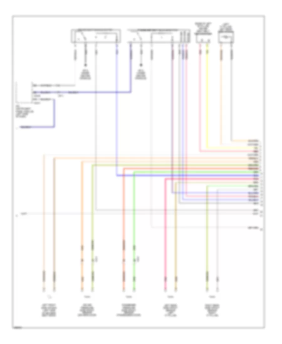 https://portal-diagnostov.com/license.html
Automotive Electricians Portal FZCO
Automotive Electricians Portal FZCO
https://portal-diagnostov.com/license.html
https://portal-diagnostov.com/license.html
Automotive Electricians Portal FZCO
Automotive Electricians Portal FZCOList of elements for Air Bag Wiring Diagram (2 of 3) for Hyundai Equus Ultimate 2012:
- (base of left "b" pillar) driver seat belt pretensioner
- (left "c" pillar) left rear side air bag
- Bts gnd
- Bts pwr
- Bts sig
- Driver pressure side impact sensor (driver's door)
- Driver seat buckle switch
- Fd11
- Fd21
- Gf13 (under center console)
- Ipm (instrument panel module) (left side of dash)
- Left front side air bag (left side
- Left rear side impact sensor (left "c" pillar)
- M40-b
- M40-c
- Mf11
- Of driver's seat back)
- Passenger pressure side impact sensor (passenger's door)
- Passenger seat buckle switch
- Pnk
- Red
- Right rear side impact sensor (right "c" pillar)
Air Bag Wiring Diagram (3 of 3) for Hyundai Equus Ultimate 2012
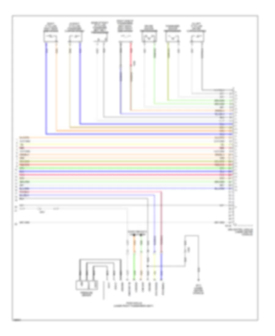 https://portal-diagnostov.com/license.html
Automotive Electricians Portal FZCO
Automotive Electricians Portal FZCO
https://portal-diagnostov.com/license.html
https://portal-diagnostov.com/license.html
Automotive Electricians Portal FZCO
Automotive Electricians Portal FZCOList of elements for Air Bag Wiring Diagram (3 of 3) for Hyundai Equus Ultimate 2012:
- (+)
- (-)
- (base of right "b" pillar) passenger seat belt pretensioner
- (in left "c" pillar) driver curtain air bag
- (in right "c" pillar) passenger curtain air bag
- (right "c" pillar) right rear side air bag
- (right side of passenger's seat back) right front side air bag
- Bts power
- Bts signal
- Can high
- Can low
- Computer data lines system
- Driver anchor pretensioner
- F81-b
- Ff03
- Gf13 (under center console)
- Gnd
- Ground
- Mf01
- Nca
- On/start in
- Passenger anchor pretensioner
- Pnk
- Pods module (under front passenger's seat)
- Pressure sensor
- Red
- Srs control module (under center console)
- Svolt
- Vout
- Vovt
Electronic Active Headrest Wiring Diagram for Hyundai Equus Ultimate 2012
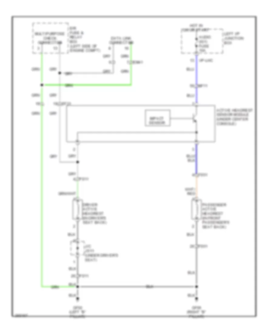 https://portal-diagnostov.com/license.html
Automotive Electricians Portal FZCO
Automotive Electricians Portal FZCO
https://portal-diagnostov.com/license.html
https://portal-diagnostov.com/license.html
Automotive Electricians Portal FZCO
Automotive Electricians Portal FZCOList of elements for Electronic Active Headrest Wiring Diagram for Hyundai Equus Ultimate 2012:
- Active headrest sensor module (under center console)
- Audio (ig1) fuse 10a
- Data link connector
- Driver active headrest (in driver's seat back)
- E/r fuse & relay box (left side of engine compt)
- Ef31
- Em41
- Fs11
- Fs51
- Gf02 (left "b" pillar)
- Gf06 (right "b" pillar)
- Hot in on or start
- I/p-lhc
- Impact sensor
- J/c js11 (under driver's seat)
- Left i/p junction box
- Mf11
- Multipurpose check connector
- Passenger active headrest (in front passenger's seat back)
Pre-Safe Seat Belt Wiring Diagram for Hyundai Equus Ultimate 2012
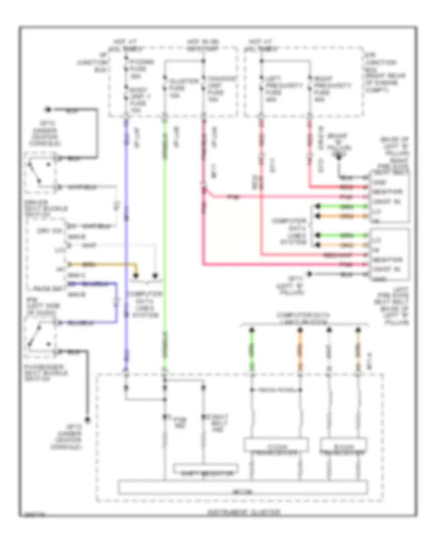 https://portal-diagnostov.com/license.html
Automotive Electricians Portal FZCO
Automotive Electricians Portal FZCO
https://portal-diagnostov.com/license.html
https://portal-diagnostov.com/license.html
Automotive Electricians Portal FZCO
Automotive Electricians Portal FZCOList of elements for Pre-Safe Seat Belt Wiring Diagram for Hyundai Equus Ultimate 2012:
- (base of left "b" pillar) right pre-safe seat belt
- (right "b" pillar)
- (under center console)
- B-can
- Body unit-1 fuse 10a
- C-can
- Chassis unit fuse 10a
- Cluster fuse 10a
- Computer data lines system
- Driver seat buckle switch
- Drv sw
- E/r junction box (right rear of engine compt)
- E/r-e1b ef21
- Ef11
- Gf11 (left "b" pillar)
- Gf12
- Gf13
- Gf13 (under center console)
- Gnd
- Hot at all times
- Hot in on or start
- I/p junction box
- I/p-lha
- I/p-lhe
- I/p-lhf
- Instrument cluster
- Ipm (left side of dash)
- Left pre-safe seat belt (base of left "b" pillar)
- Left presafety fuse 40a
- M11-a
- M40-b
- M40-c
- Mem pwr
- Mf11
- Micom
- On/st in
- P/conn fuse 30a
- Pass sw
- Passenger seat buckle switch
- Pnk
- Psb ind
- Red
- Right presafety fuse 40a
- Seat belt ind
- Shift resistor
- Transceiver
TRANSMISSION
4.6L
4.6L, Transmission Wiring Diagram for Hyundai Equus Ultimate 2012
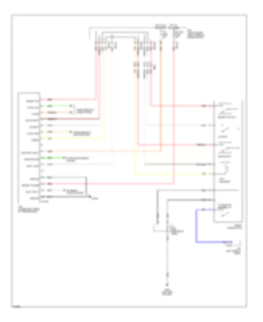 https://portal-diagnostov.com/license.html
Automotive Electricians Portal FZCO
Automotive Electricians Portal FZCO
https://portal-diagnostov.com/license.html
https://portal-diagnostov.com/license.html
Automotive Electricians Portal FZCO
Automotive Electricians Portal FZCOList of elements for 4.6L, Transmission Wiring Diagram for Hyundai Equus Ultimate 2012:
- "p" position switch
- Atm solenoid
- B/up lp rly
- C-can high
- C-can low
- Computer data lights system
- Computer data lines system
- Cranking sig
- Ctg-zf
- Down shift
- E/r junction box (right rear of engine compt)
- E/r-ca
- E/r-cb
- E/r-e2a
- E/r-e2b
- Ecu (b+) fuse 10a
- Em41
- Exterior lights system
- Gm01 (left end of dash)
- Ground
- Gtg01
- Hot at all times
- Hot in on or start
- Ipm (left side of dash)
- J/c jm05 (center of dash)
- K-kine
- M40-b
- Memory power
- On/start input
- Red
- Select sw
- Select switch
- Shift lock
- Sport mode switch
- Starting/charging system
- Tcm (lower right rear of transmission)
- Tcu fuse 15a
- U-drmu
- Up shift
5.0L
5.0L, Transmission Wiring Diagram for Hyundai Equus Ultimate 2012
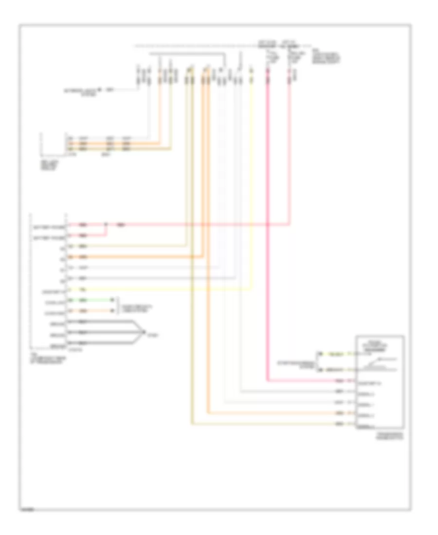 https://portal-diagnostov.com/license.html
Automotive Electricians Portal FZCO
Automotive Electricians Portal FZCO
https://portal-diagnostov.com/license.html
https://portal-diagnostov.com/license.html
Automotive Electricians Portal FZCO
Automotive Electricians Portal FZCOList of elements for 5.0L, Transmission Wiring Diagram for Hyundai Equus Ultimate 2012:
- Battery power
- C-can high
- C-can low
- Computer data lines system
- Ctg-tg
- E/r junction box (right rear of engine compt)
- E/r-ca
- E/r-cb
- E/r-e2a
- E/r-e2b
- Ecu (b+) fuse 15a
- Em21
- Exterior lights system
- Ground
- Gtg01
- Hot at all times
- Hot in on or start
- Key lock control module
- M-76
- On/start in
- P/n sw (p.n position sw close)
- Pnk
- Red
- Signal 1
- Signal 2
- Signal 3
- Signal 4
- Starting/charging system
- Tcm (lower right rear of transmission)
- Tcu fuse 15a
- Transmission range switch
TRUNK, TAILGATE, FUEL DOOR
Trunk & Fuel Door Release Wiring Diagram, with Power Decklid for Hyundai Equus Ultimate 2012
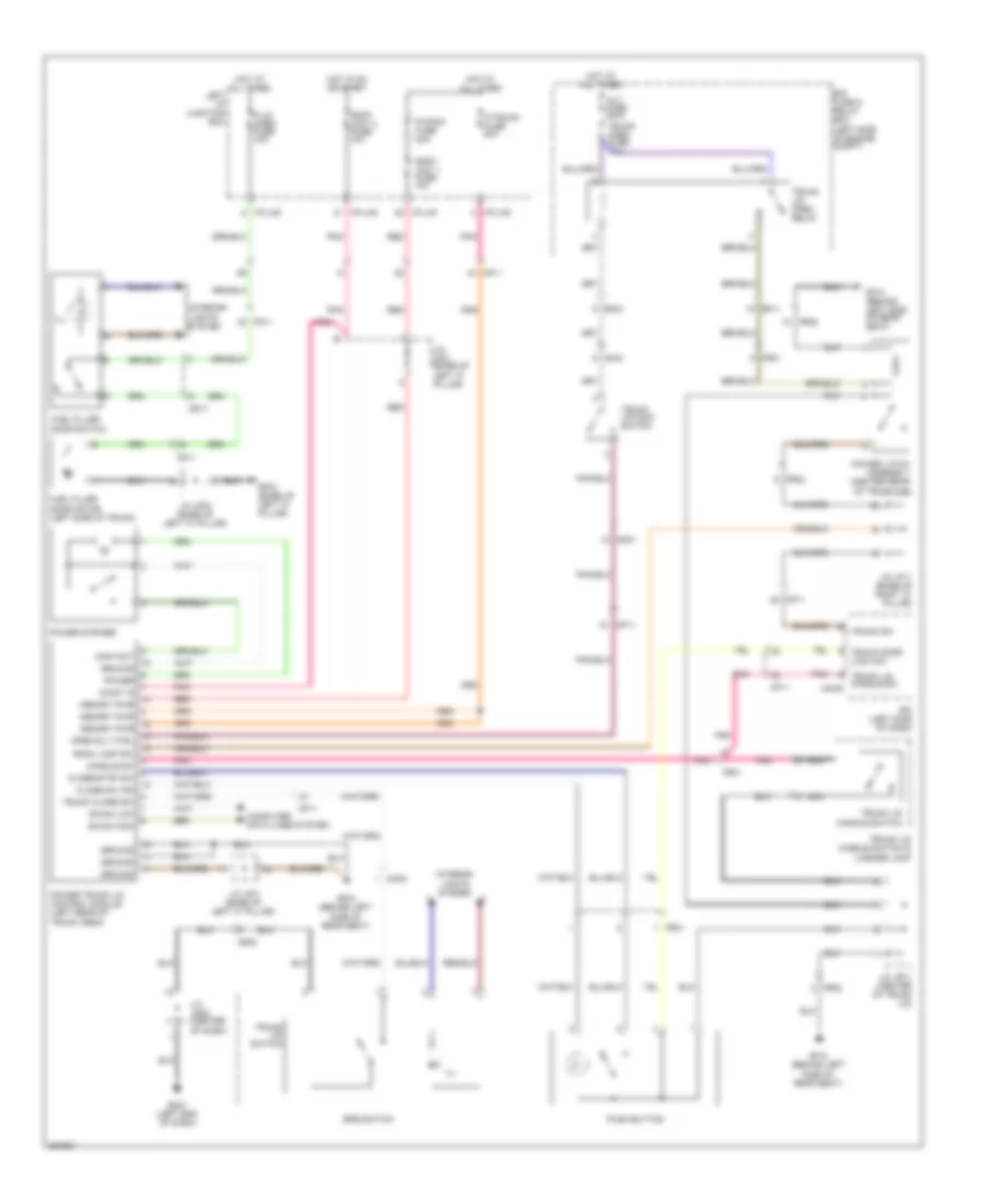 https://portal-diagnostov.com/license.html
Automotive Electricians Portal FZCO
Automotive Electricians Portal FZCO
https://portal-diagnostov.com/license.html
https://portal-diagnostov.com/license.html
Automotive Electricians Portal FZCO
Automotive Electricians Portal FZCOList of elements for Trunk & Fuel Door Release Wiring Diagram, with Power Decklid for Hyundai Equus Ultimate 2012:
- Alt fuse 200a
- B-can high
- B-can low
- Body unit 1 fuse 10a
- Body unit 2 fuse 10a
- Close sw ind
- Close/stop sw
- Computer data lines system
- Contact
- Dd11
- Door switch
- E/r fuse & relay box (left side of engine compt)
- Ef11
- Em21
- Epb switch
- F/lid open fuse 10a
- Fd11
- Fr01
- Fr02
- Fuel filler
- Fuel filler door motor (left side of trunk)
- Gf03 (base of left "c" pillar)
- Gf04 (behind left side of rear seat)
- Gf10 (behind left side of rear seat)
- Gm01 (left end of dash)
- Ground
- Handle sw
- Hot at all times
- Hot in on or start
- I/p-lhd
- I/p-lhf
- I/p-lhg
- Ill
- Interior
- Interior lights system
- Ipm (left side of dash)
- J/c jf01 (base of left "c" pillar)
- J/c jf02 (base of left "c" pillar)
- J/c jf11 (base of right "c" pillar)
- J/c jm05 (center of dash)
- J/c jr11 (center of trunk lid)
- Left i/p junction box
- Lights system
- Memory pwr
- Mf11
- Mm01
- Mm02
- Nca
- On/st in
- Open rly ctrl
- P/conn fuse 30a
- P/trunk fuse 30a
- Pnk
- Power
- Power latch assembly (center rear of trunk lid)
- Power striker
- Power trunk lid control module (left rear of trunk area)
- Push button
- Red
- Room lamp sw
- Trunk close sw
- Trunk door lock sw
- Trunk lid handle sw m40-b
- Trunk lid handle switch
- Trunk lid handle switch & license lamp
- Trunk lid main switch
- Trunk lid open relay
- Trunk lid switch
- Trunk open fuse 10a
- Trunk sw
Trunk & Fuel Door Release Wiring Diagram, without Power Decklid for Hyundai Equus Ultimate 2012
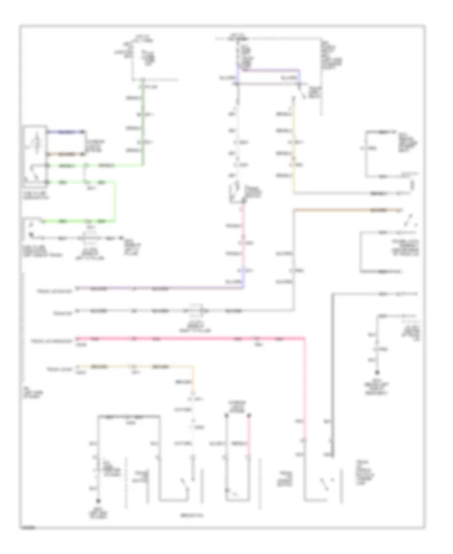 https://portal-diagnostov.com/license.html
Automotive Electricians Portal FZCO
Automotive Electricians Portal FZCO
https://portal-diagnostov.com/license.html
https://portal-diagnostov.com/license.html
Automotive Electricians Portal FZCO
Automotive Electricians Portal FZCOList of elements for Trunk & Fuel Door Release Wiring Diagram, without Power Decklid for Hyundai Equus Ultimate 2012:
- Alt fuse 200a
- Dd11
- Door switch
- E/r fuse & relay box (left side of engine compt)
- Ef11
- Em21
- Epb switch
- F/lid open fuse 10a
- Fd11
- Fr01
- Fr02
- Fuel filler
- Fuel filler door motor (left side of trunk)
- Gf03 (base of left "c" pillar)
- Gf10 (behind left side of rear seat)
- Gm01 (left end of dash)
- Hot at all times
- I/p-lhd
- Ill
- Interior
- Interior lights system
- Ipm (left side of dash)
- J/c jf02 (base of left "c" pillar)
- J/c jf11 (base of right "c" pillar)
- J/c jm05 (center
- J/c jr11 (center of trunk lid)
- Left i/p junction box
- Lights system
- M40-b
- M40-c
- Mf11
- Mm01
- Mm02
- Nca
- Of dash)
- Pnk
- Power latch assembly (center rear of trunk lid)
- Trunk lid handle sw
- Trunk lid handle switch
- Trunk lid handle switch & license lamp
- Trunk lid main sw
- Trunk lid main switch
- Trunk lid sw
- Trunk lid switch
- Trunk open fuse 10a
- Trunk open relay
- Trunk sw
WARNING SYSTEMS
Chime Wiring Diagram for Hyundai Equus Ultimate 2012
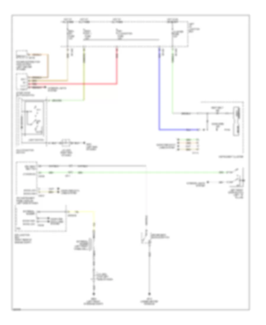 https://portal-diagnostov.com/license.html
Automotive Electricians Portal FZCO
Automotive Electricians Portal FZCO
https://portal-diagnostov.com/license.html
https://portal-diagnostov.com/license.html
Automotive Electricians Portal FZCO
Automotive Electricians Portal FZCOList of elements for Chime Wiring Diagram for Hyundai Equus Ultimate 2012:
- Auto
- B-can high
- B-can low
- Body unit 1 fuse 10a
- Cluster fuse 10a
- Computer data lines system
- Door open ind
- Driver seat buckle switch
- Drv seat belt sw
- E/r junction box (right rear of engine compt)
- E/r-e1b
- Escl sw fuse 10a
- External buzzer
- External buzzer (left front wheelwell)
- Fam
- Fam-b
- Ge03 (left front of engine compt)
- Gf13 (under center console)
- Gm01 (left end of dash)
- Hot at all times
- Hot in on or start
- I/p-lhe
- I/p-lhf
- Ill(+)
- Ill(-)
- Ind
- Instrument cluster
- Interior lights system
- Ipm (instrument panel module) (left side of dash)
- J/c je02 (top left side of dash)
- J/c jm03 (right end of dash)
- Key illumination fuse 10a
- Left front door switch (left ``b" pillar)
- Left i/p junction box
- Lf door sw
- Light switch
- M/f sw ecu
- M11-a
- M40-b
- M40-c
- M51-b
- Mf11
- Micom
- Multi-function switch
- Nca
- Off
- Power distribution module (pdm) (left center of dash)
- Red
- Resistor shift
- Seat belt
- Ssb sw1
- Start stop button switch
- Sw1
Tire Pressure Monitoring Wiring Diagram for Hyundai Equus Ultimate 2012
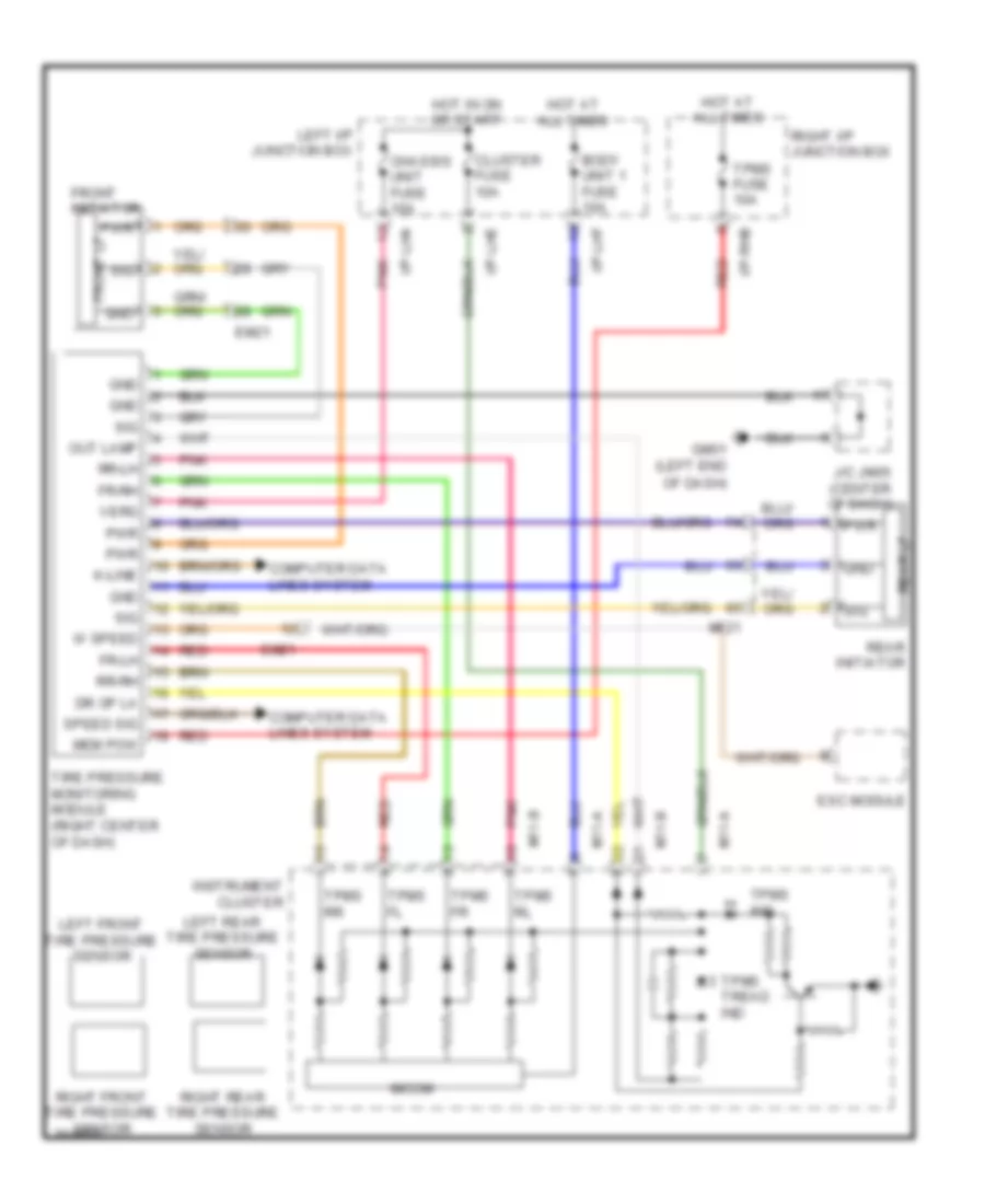 https://portal-diagnostov.com/license.html
Automotive Electricians Portal FZCO
Automotive Electricians Portal FZCO
https://portal-diagnostov.com/license.html
https://portal-diagnostov.com/license.html
Automotive Electricians Portal FZCO
Automotive Electricians Portal FZCOList of elements for Tire Pressure Monitoring Wiring Diagram for Hyundai Equus Ultimate 2012:
- Body unit 1 fuse 10a
- Chassis unit fuse 10a
- Cluster fuse 10a
- Computer data lines system
- Dr op la
- Em21
- Esc module
- Fr-lh
- Fr-rh
- Front initiator
- Front lf
- Gm01 (left end
- Gnd
- Hot at all times
- Hot in on or start
- I/p-lha
- I/p-lhe
- I/p-lhf
- I/p-rhb
- Instrument cluster
- J/c jm05 (center of dash)
- K-line
- Left front tire pressure sensor
- Left i/p junction box
- Left rear tire pressure sensor
- M11-a
- M11-b
- Mem pow
- Mf21
- Micom
- Of dash)
- Out lamp
- Pnk
- Pwr
- Rear initiator
- Rear lf
- Red
- Right front tire pressure sensor
- Right i/p junction box
- Right rear tire pressure sensor
- Rr-lh
- Rr-rh
- Sig
- Speed sig
- Tire pressure monitoring module (right center of dash)
- Tpms fl
- Tpms fr
- Tpms fuse 10a
- Tpms ind
- Tpms rl
- Tpms rr
- Tpms tread ind
- Verg
- W speed
WIPER/WASHER
Wiper/Washer Wiring Diagram for Hyundai Equus Ultimate 2012
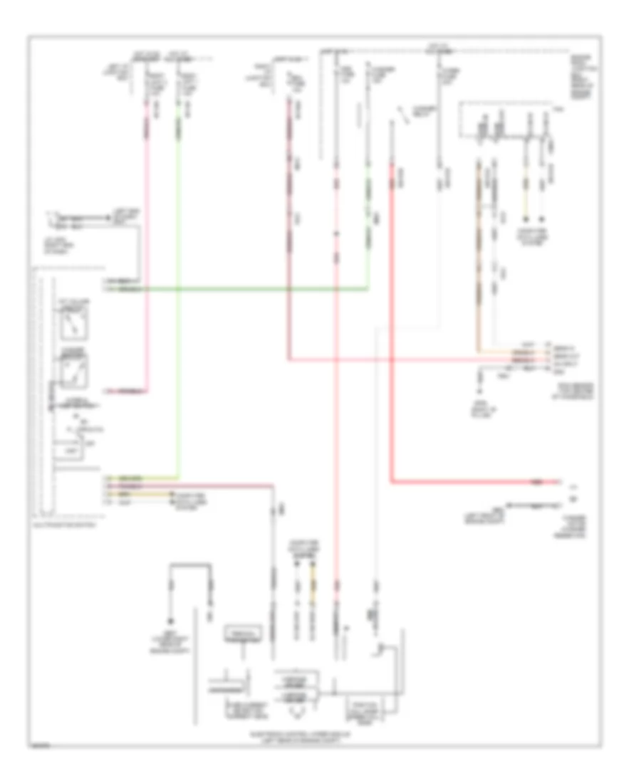 https://portal-diagnostov.com/license.html
Automotive Electricians Portal FZCO
Automotive Electricians Portal FZCO
https://portal-diagnostov.com/license.html
https://portal-diagnostov.com/license.html
Automotive Electricians Portal FZCO
Automotive Electricians Portal FZCOList of elements for Wiper/Washer Wiring Diagram for Hyundai Equus Ultimate 2012:
- (left end of dash) gm01
- (right "b"
- Aqs fuse 10a
- B-can hi
- B-can high
- B-can lo
- B-can low
- Body unit 1 fuse 10a
- Body unit 2 fuse 10a
- Computer data lines system
- E/r-e1a
- E/r-e1b
- E/r-e2b
- Ecm fuse 10a
- Ef21
- Electronic control wiper module (left rear of engine compt)
- Em31
- Engine room junction box (right rear of engine compt)
- Fam
- Fam-b
- Fr21
- Ge03 (left front of engine compt)
- Ge07 (lower right rear of engine compt)
- Gf06
- Gnd
- H-bridge driver
- Hot at all times
- Hot in on
- Hot in on or start
- I/p-lhf
- I/p-lhg
- I/p-rha
- Int (auto)
- Int volume switch
- J/c jm03 (right end of dash)
- Left i/p junction box
- M/f sw ecu
- Mf21
- Mist
- Multifunction switch
- Off
- On input
- Over current detection current meas
- Pillar)
- Position hall snsr speed hall snsr
- Power mem
- Rain sens in
- Rain sens out
- Rain sensor (top center of windshield)
- Red
- Reg
- Right i/p junction box
- Sens in
- Sens out
- Terminal protection
- Washer fuse 15a
- Washer motor (washer reservoir)
- Washer relay
- Washer switch
- Watch-dog
- Wiper & mist switch
- Wiper fuse 30a
- Wiper low

 Čeština
 Dansk
Dansk Deutsch
 Ελληνικά
 English
 English
 Español
 Suomi
Suomi Français
 Français
 עברית
עברית Hrvatski
 Magyar
 Italiano
 日本語
日本語 한국어
한국어 Nederlands
 Polski
 Português
 Português
 Română
 Русский
 Slovenčina
 Slovenščina
 Svenska
 中文 (中国)
