AIR CONDITIONING
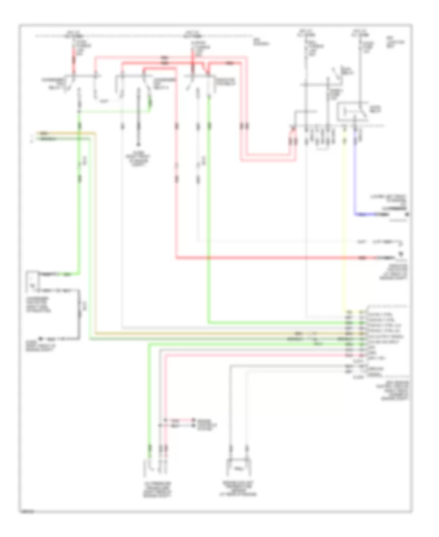
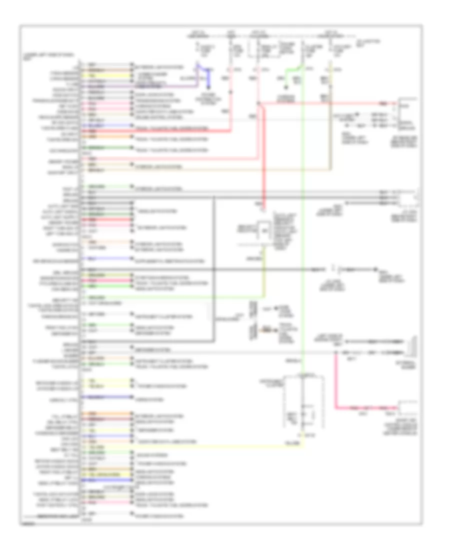
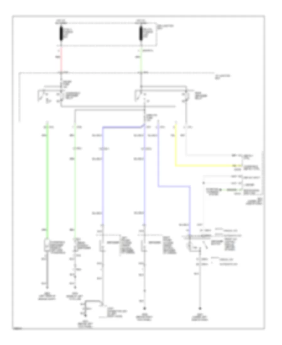
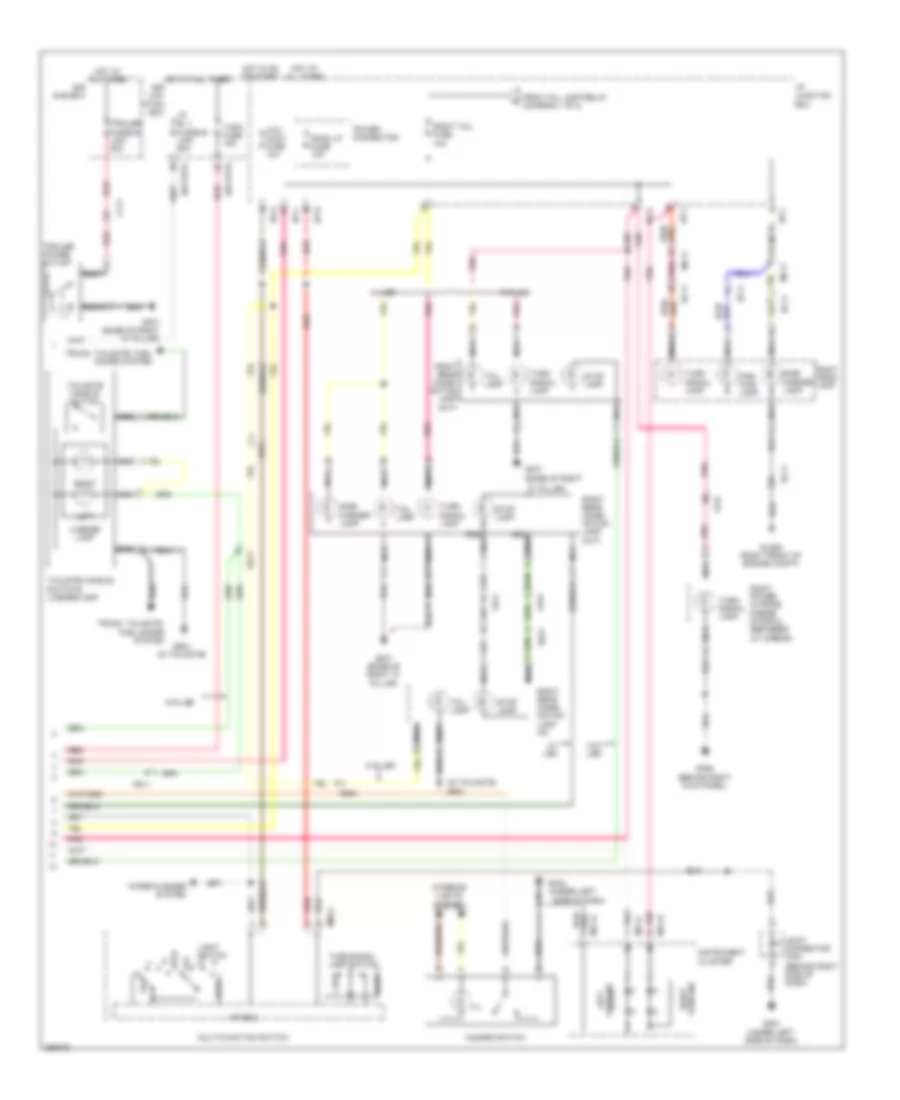
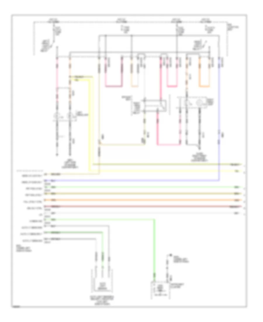
Automatic A/C Wiring Diagram (1 of 2) for Hyundai Veracruz Limited 2012
 https://portal-diagnostov.com/license.html
Automotive Electricians Portal FZCO
Automotive Electricians Portal FZCO
https://portal-diagnostov.com/license.html
https://portal-diagnostov.com/license.html
Automotive Electricians Portal FZCO
Automotive Electricians Portal FZCO
List of elements for Automatic A/C Wiring Diagram (1 of 2) for Hyundai Veracruz Limited 2012:
- (behind right end of dash) gm05
- (on hvac assembly) evaporator sensor
- A/c output
- A/c select signal
- A/con fuse 10a
- Active incar sensor (behind right center side of dash)
- Ambient temp sens (+)
- Ambient temperature sensor (behind center of front bumper)
- Aqs sensor (behind center of front bumper)
- Aqs signal
- Blower fusible link 40a
- Blower relay
- Blower rly on input
- Computer data lines system
- Defogger ind
- Defogger sw
- Defogger system
- Driver temperature actuator (left side of hvac assembly)
- Drv photo sensor (-)
- Drv temp cool
- Drv temp f/b
- Drv temp warm
- E/r junction box
- E/r-frta
- Ee31
- Em31
- Evaporator sensor (+)
- Fet (d)
- Fet (g)
- Front a/c control module (center of dash)
- Front blower motor (below right side of dash, on bottom of hvac assembly)
- Front fet (field effect transistor) (on hvac unit)
- Ge03 (left rear of engine compt)
- Gm01 (under left side of dash)
- Gm04 (under left side of dash)
- Ground
- H/lp aqs fuse 10a
- Hot at all times
- Hot in on
- I/p junction box
- I/p-a
- I/p-c
- I/p-h
- I/p-k
- I/p-l
- Ill (+)
- Ill (-)
- Incar sensor
- Intake actuator (on hvac assembly)
- Intake f/b
- Intake fre
- Intake rec
- Interior lights system
- K line
- M05-a
- M05-b
- Memory pwr
- Mode actuator (left side of hvac assembly)
- Mode def
- Mode f/b
- Mode vent
- Motor (+)
- Motor (-)
- On input
- Pass photo sensor (-)
- Pass temp cool
- Pass temp f/b
- Pass temp warm
- Passenger temperature actuator (on hvac assembly)
- Photo sensor (top right side of dash)
- Pnk
- Power connector
- Rear a/c circuit
- Rear c line
- Red
- Room lp fuse 15a
- Sensor ground
- Sensor ref (5v)
- Vehicle speed sensor
- Water temperature sensor (on hvac assembly)
- Wts (+)
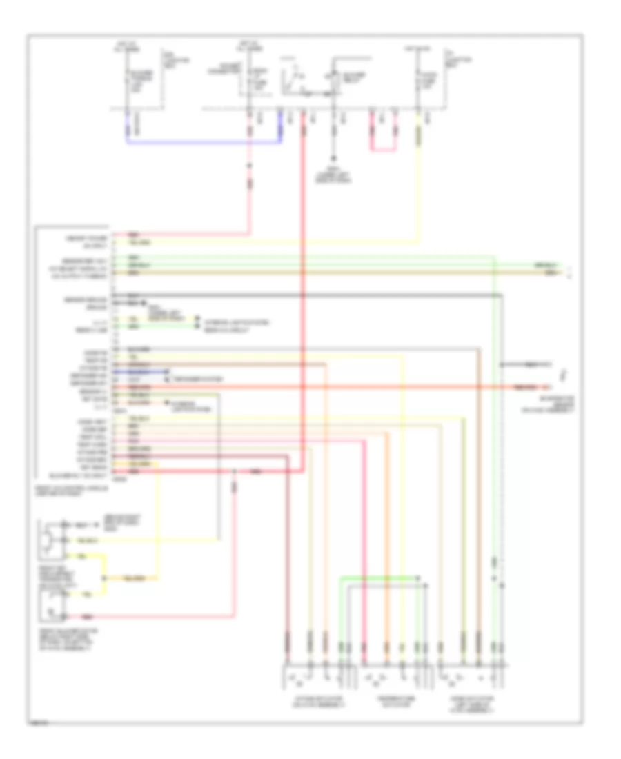
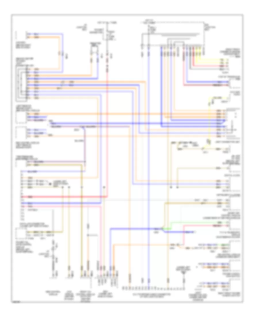
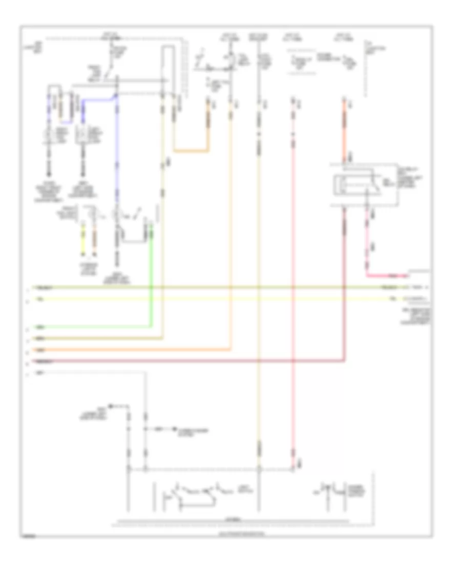
Automatic A/C Wiring Diagram (2 of 2) for Hyundai Veracruz Limited 2012
 https://portal-diagnostov.com/license.html
Automotive Electricians Portal FZCO
Automotive Electricians Portal FZCO
https://portal-diagnostov.com/license.html
https://portal-diagnostov.com/license.html
Automotive Electricians Portal FZCO
Automotive Electricians Portal FZCOList of elements for Automatic A/C Wiring Diagram (2 of 2) for Hyundai Veracruz Limited 2012:
- (lower left front of engine) a/c compressor
- A/c output signal
- A/c pressure transducer (right rear of engine compt)
- A/c rly ctrl
- A/c sw on input
- A/con fuse 10a
- A/con relay
- C/fan fusible link 40a
- Clg-a
- Clg-b
- Condenser fan motor (right side of radiator)
- Condenser fan relay 1
- Condenser fan relay 2
- E/r junction box
- E/r sub box
- E/r-clg
- E/r-frta
- E/r-frtb
- Ec21
- Ecm (engine control module) (right front corner of engine compt)
- Ecu fusible link 30a
- Engine controls system
- Engine coolant temperature sensor (at rear of engine)
- Fan rly ctrl (hi)
- Fan rly ctrl (lo)
- Glg05 (right front of engine compt)
- Gnd
- Ground
- Hot at all times
- Main relay
- Main rly ctrl
- Mc11
- Nca
- Pnk
- R/fan fusible link 40a
- Radiator fan motor (at front of engine compt)
- Radiator fan relay
- Red
- Sig
- Signal
- Snsr 3 fuse 10a
- Sply (5v)
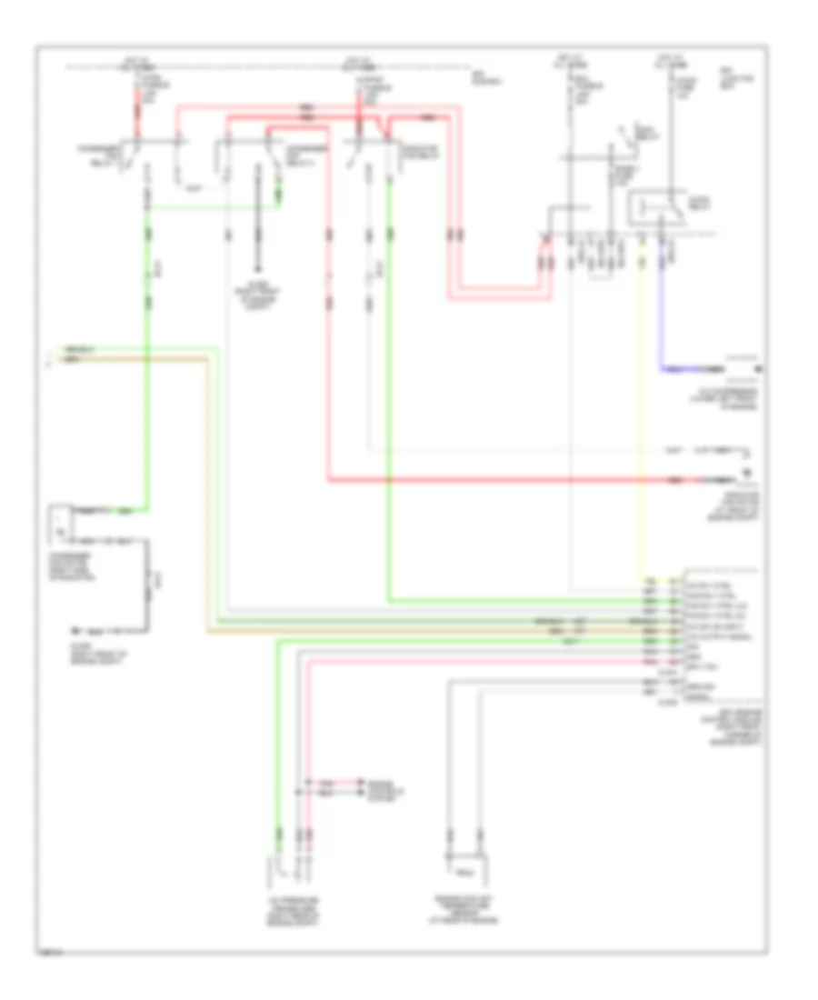
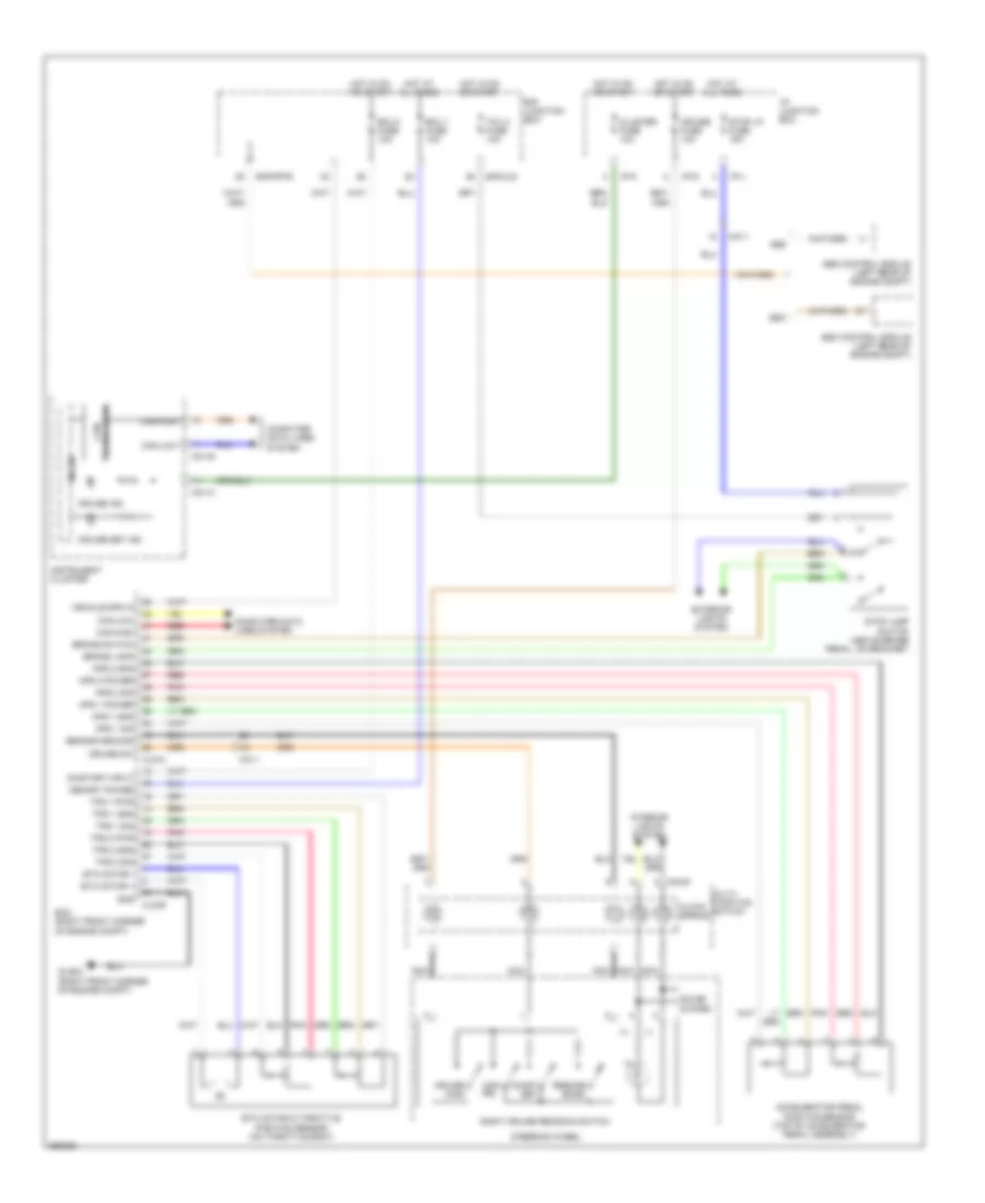
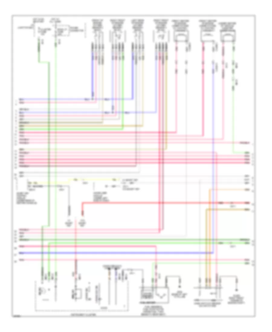
Manual A/C Wiring Diagram (1 of 2) for Hyundai Veracruz Limited 2012
 https://portal-diagnostov.com/license.html
Automotive Electricians Portal FZCO
Automotive Electricians Portal FZCO
https://portal-diagnostov.com/license.html
https://portal-diagnostov.com/license.html
Automotive Electricians Portal FZCO
Automotive Electricians Portal FZCOList of elements for Manual A/C Wiring Diagram (1 of 2) for Hyundai Veracruz Limited 2012:
- (behind right end of dash) gm05
- A/c output (thermo)
- A/c select signal (hi)
- A/con fuse 10a
- Blower fusible link 40a
- Blower relay
- Blower rly on input
- Defogger ind
- Defogger sw
- Defogger system
- E/r junction box
- E/r-frta
- Evaporator sensor (on hvac assembly)
- Fet drain
- Fet gate
- Front a/c control module (center of dash)
- Front blower motor (below right side of dash, on bottom of hvac assembly)
- Front fet (field effect transistor) (on hvac unit)
- Gm01 (under left side of dash)
- Gm04 (under left side of dash)
- Ground
- Hot at all times
- Hot in on
- I/p junction box
- I/p-a
- I/p-h
- I/p-k
- I/p-l
- Ill (+)
- Ill (-)
- Intake actuator (on hvac assembly)
- Intake f/b
- Intake fre
- Intake rec
- Interior lights system
- M06-a
- M06-b
- Memory power
- Mode actuator (left side of hvac assembly)
- Mode def
- Mode f/b
- Mode vent
- On input
- Pnk
- Power connector
- Rear a/c circuit
- Rear c line
- Red
- Room lp fuse 15a
- Sensor (+)
- Sensor ground
- Sensor ref (+5v)
- Temp cool
- Temp f/b
- Temp warm
- Temperature actuator
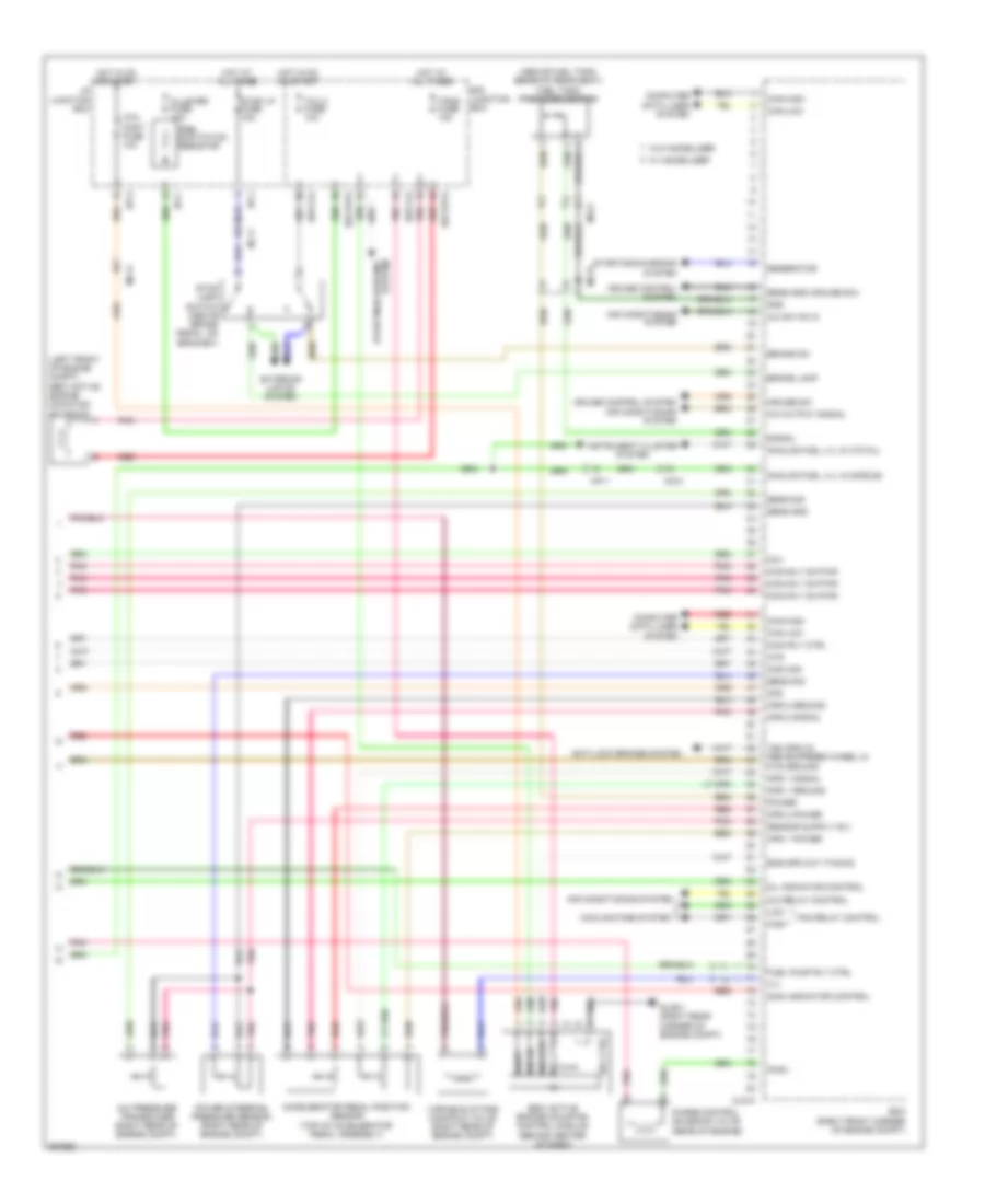
Manual A/C Wiring Diagram (2 of 2) for Hyundai Veracruz Limited 2012
 https://portal-diagnostov.com/license.html
Automotive Electricians Portal FZCO
Automotive Electricians Portal FZCO
https://portal-diagnostov.com/license.html
https://portal-diagnostov.com/license.html
Automotive Electricians Portal FZCO
Automotive Electricians Portal FZCOList of elements for Manual A/C Wiring Diagram (2 of 2) for Hyundai Veracruz Limited 2012:
- A/c compressor (lower left front of engine)
- A/c output signal
- A/c pressure transducer (right rear of engine compt)
- A/c rly ctrl
- A/c sw on input
- A/con fuse 10a
- A/con relay
- C/fan fusible link 40a
- Clg-a
- Clg-b
- Condenser fan motor (right side of radiator)
- Condenser fan relay 1
- Condenser fan relay 2
- E/r junction box
- E/r sub box
- E/r-clg
- E/r-frta
- E/r-frtb
- Ec21
- Ecm (engine control module) (right front corner of engine compt)
- Ecu fusible link 30a
- Engine controls system
- Engine coolant temperature sensor (at rear of engine)
- Fan rly ctrl (hi)
- Fan rly ctrl (lo)
- Glg05 (right front of engine compt)
- Gnd
- Ground
- Hot at all times
- Main relay
- Main rly ctrl
- Mc11
- Nca
- Pnk
- R/fan fusible link 40a
- Radiator fan motor (at front of engine compt)
- Radiator fan relay
- Red
- Sig
- Signal
- Snsr 3 fuse 10a
- Sply (5v)
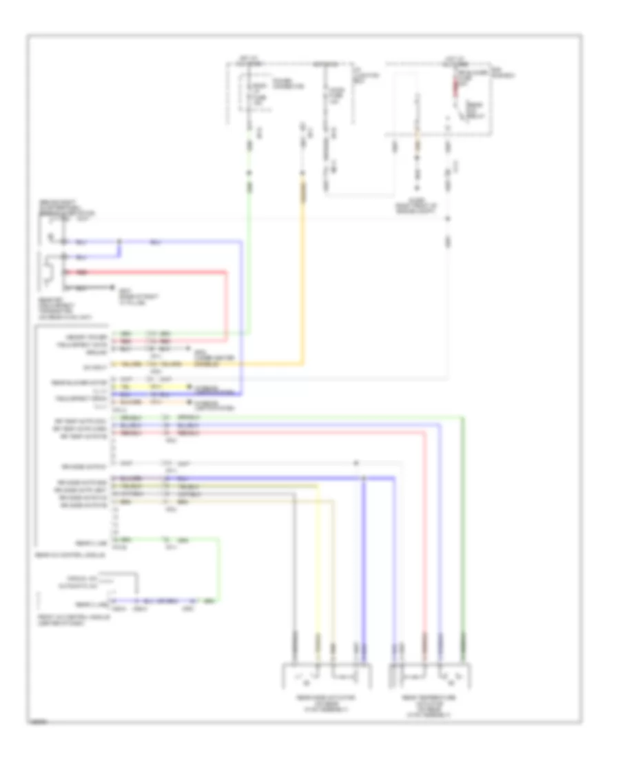
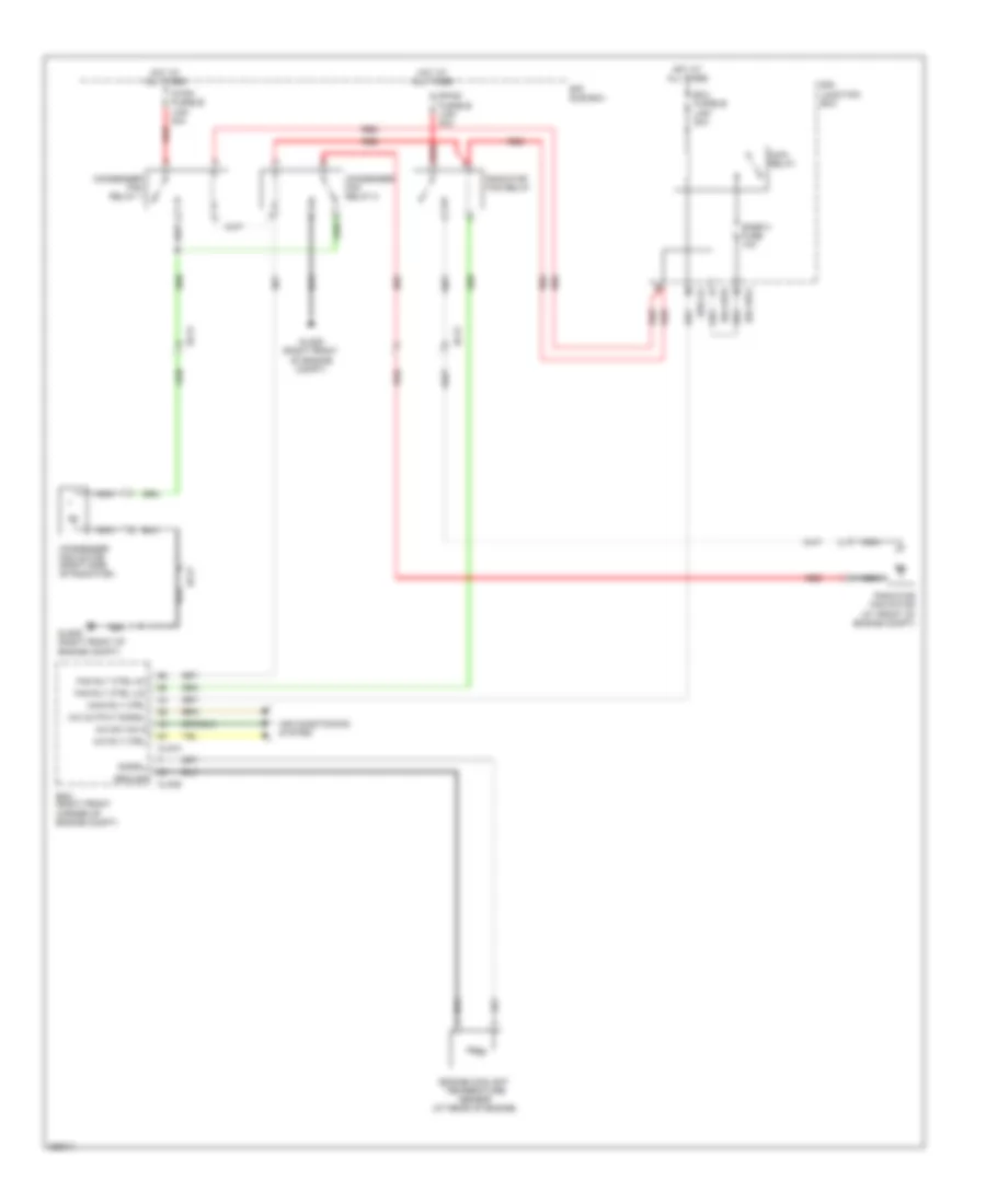
Rear A/C Wiring Diagram for Hyundai Veracruz Limited 2012
 https://portal-diagnostov.com/license.html
Automotive Electricians Portal FZCO
Automotive Electricians Portal FZCO
https://portal-diagnostov.com/license.html
https://portal-diagnostov.com/license.html
Automotive Electricians Portal FZCO
Automotive Electricians Portal FZCOList of elements for Rear A/C Wiring Diagram for Hyundai Veracruz Limited 2012:
- (behind right quarterpanel) rear blower motor
- A/con fuse 10a
- Automatic a/c
- Cf11
- E/r sub box
- F70-a
- F70-b
- Ff11
- Ff21
- Field effect drain
- Field effect gate
- Front a/c control module (center of dash)
- Gf02 (under center console)
- Gf07 (base of right "c" pillar)
- Glg05 (right front of engine compt)
- Ground
- Hot at all times
- Hot in on
- I/p junction box
- I/p-e
- I/p-f
- I/p-h
- Ill (+)
- Ill (-)
- Interior lights system
- M05-a
- M06-a
- Manual a/c
- Mc11
- Memory power
- Mf61
- On input
- Power connector
- Rear a/c control module
- Rear a/c relay
- Rear blower motor
- Rear c line
- Rear fet (field effect transistor) (on rear hvac unit)
- Rear mode actuator (on rear hvac assembly)
- Rear temperature actuator (on rear hvac assembly)
- Red
- Room lp fuse 15a
- Rr blower fuse 20a red
- Rr mode actr 5v
- Rr mode actr f/b
- Rr mode actr flr
- Rr mode actr gnd
- Rr mode actr vent
- Rr temp actr cool
- Rr temp actr f/b
- Rr temp actr warm
ANTI-LOCK BRAKES
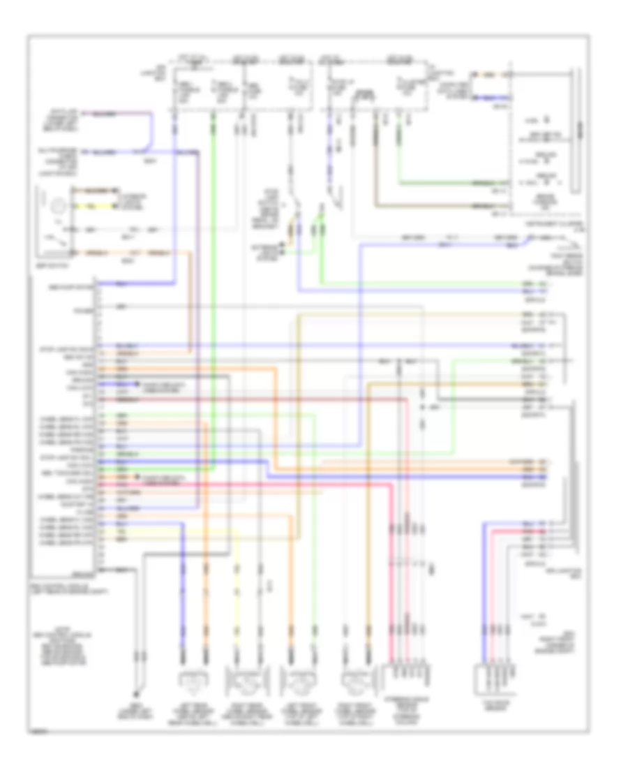
Anti-lock Brakes Wiring Diagram, with ESC for Hyundai Veracruz Limited 2012
 https://portal-diagnostov.com/license.html
Automotive Electricians Portal FZCO
Automotive Electricians Portal FZCO
https://portal-diagnostov.com/license.html
https://portal-diagnostov.com/license.html
Automotive Electricians Portal FZCO
Automotive Electricians Portal FZCOList of elements for Anti-lock Brakes Wiring Diagram, with ESC for Hyundai Veracruz Limited 2012:
- Abs 1 fusible link 40a
- Abs 2 fusible link 40a
- Abs fuse 10a
- Abs ind
- Abs pump motor
- Abs, tcs & esc sol
- Brake warning ind
- Can (high)
- Can (low)
- Can high
- Can low
- Check connector (at e/r junction box)
- Clg-a
- Cluster fuse 10a
- Computer data lines system
- Data link connector (lower left end of dash)
- Diode
- E/r junction box
- E/r-clg
- E/r-frta
- E/r-frtb
- Ecm (right front corner of engine compt)
- Ef11
- Em01
- Em11
- Em21
- Esc control module (left rear of engine compt)
- Esc ind
- Esc off ind
- Esc sw on
- Esp switch
- Exterior lights system
- Foot brake switch (on base of parking brake lever)
- Ge02 (under left end of dash)
- Gnd
- Ground
- Hot at all times
- Hot in on or start
- I/p junction box
- I/p-h
- I/p-j
- I/p-k
- Ill
- Instrument cluster
- Interior lights system
- K-line
- Left front wheel sensor (top of left wheelwell)
- Left rear wheel sensor (above left rear wheelwell)
- M01-a
- M01-b
- M01-c
- Mc11
- Micom
- Multipurpose
- Nca
- Note: esc control module contains: esc solenoids, abs solenoids, tcs solenoids & abs pump motor
- On/start in
- Parking
- Pnk
- Power
- Right front wheel sensor (top of right wheelwell)
- Right rear wheel sensor (above right rear wheelwell)
- St1
- St2
- Steering angle sensor (top of steering column)
- Stn
- Stop lamp sw sig l
- Stop lamp sw sig s
- Stop lamp switch (above brake pedal, on bracket)
- Stop lp fuse 15a
- Tcu 2 fuse 10a
- Wheel sens fl (wp)
- Wheel sens fl (ws)
- Wheel sens fr (wp)
- Wheel sens fr (ws)
- Wheel sens out (fr)
- Wheel sens rl (wp)
- Wheel sens rl (ws)
- Wheel sens rr (wp)
- Wheel sens rr (ws)
- Yaw rate sensor
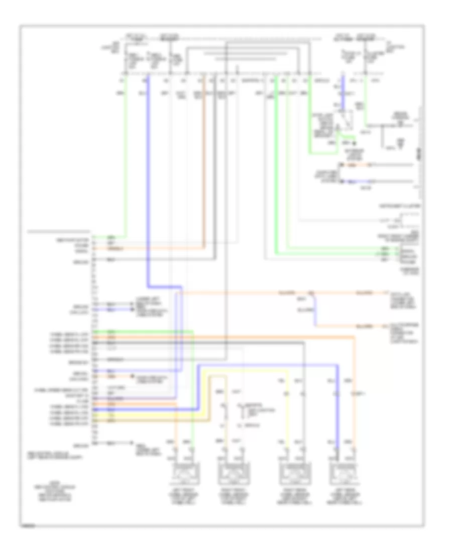
Anti-lock Brakes Wiring Diagram, without ESC for Hyundai Veracruz Limited 2012
 https://portal-diagnostov.com/license.html
Automotive Electricians Portal FZCO
Automotive Electricians Portal FZCO
https://portal-diagnostov.com/license.html
https://portal-diagnostov.com/license.html
Automotive Electricians Portal FZCO
Automotive Electricians Portal FZCOList of elements for Anti-lock Brakes Wiring Diagram, without ESC for Hyundai Veracruz Limited 2012:
- (under left end of dash) ge02 computer data lines system
- Abs 1 fusible link 40a
- Abs 2 fusible link 40a
- Abs control module (left rear of engine compt)
- Abs fuse 10a
- Abs ind
- Abs pump motor
- Abs sol
- Brake sw
- Brake warning ind
- Can (high)
- Can (low)
- Clg-a
- Cluster fuse 10a
- Computer data lines system
- Data link connector (lower left end of dash)
- E/r junction box
- E/r-clg
- E/r-frtb
- Ecm (right front corner of engine compt)
- Ef11
- Em31
- Exterior lights system
- G-sensor (w/ 4wd)
- Ge02 (under left end of dash)
- Ground
- Hot at all times
- Hot in on or start
- I/p junction box
- I/p-j
- I/p-k
- Instrument cluster
- K-line
- Left front wheel sensor (top of left wheelwell)
- Left rear wheel sensor (above left rear wheelwell)
- M01-b
- M01-c
- Mc11
- Micom
- Multipurpose check connector (at e/r junction box)
- Nca
- Note: abs control module contains: abs solenoids &
- On/start in
- Power
- Right front wheel sensor (top of right wheelwell)
- Right rear wheel sensor (above right rear wheelwell)
- Signal
- Stop lamp switch (above brake pedal, on bracket)
- Stop lp fuse 15a
- Wheel sens fl (wp)
- Wheel sens fl (ws)
- Wheel sens fr (wp)
- Wheel sens fr (ws)
- Wheel sens rl (wp)
- Wheel sens rl (ws)
- Wheel sens rr (wp)
- Wheel sens rr (ws)
- Wheel speed sens out (fr)
ANTI-THEFT
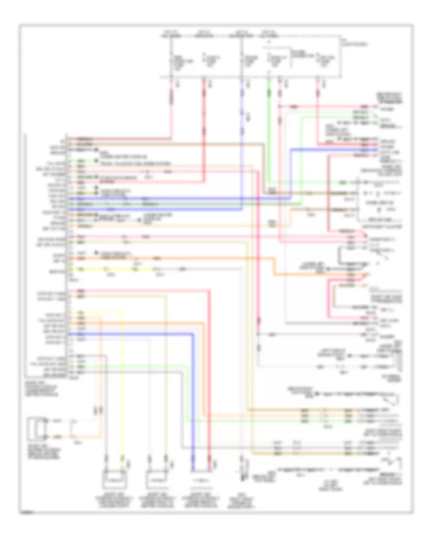
Forced Entry Wiring Diagram for Hyundai Veracruz Limited 2012
 https://portal-diagnostov.com/license.html
Automotive Electricians Portal FZCO
Automotive Electricians Portal FZCO
https://portal-diagnostov.com/license.html
https://portal-diagnostov.com/license.html
Automotive Electricians Portal FZCO
Automotive Electricians Portal FZCOList of elements for Forced Entry Wiring Diagram for Hyundai Veracruz Limited 2012:
- (behind right kick panel) gf06
- (behind right side of dash) rf receiver
- (under left center of dash) (w/o power tail gate) icm relay box
- (under left side of dash)
- Auto light sensor & security indicator (auto light sensor: top left side of dash)
- Bcm (under left side of dash)
- Can-high
- Can-low
- Computer data lines system
- D14-a
- D14-b
- Do3-a
- Do3-b
- Door lock relay
- Door unlock relay
- Dr lk
- Dr lock
- Dr lock fuse 20a
- Dr unlk
- Dr unlock
- Ee31
- Em11
- Eps fuse 10a
- Fd11
- Fd12
- Fd21
- Fd22
- Fl d/unlock sw
- Fl door sw
- Fl key lock sw
- Fl key unlock sw
- Fr11
- Fr21
- Ge01 (left side of engine compt)
- Gf03 (behind left kick panel)
- Gf06 (behind right kick panel)
- Gf07 (base of right "c" pillar)
- Gf08 (base of left "c" pillar)
- Gm01
- Gnd
- Gr01 (in tailgate)
- Hood switch
- Hood switch (left front of engine compt)
- Hot at all times
- Hot in on
- I/p junction box
- I/p-d
- I/p-e
- I/p-h
- I/p-j
- Immobilizer circuit
- Interior lights system
- Interior lights system computer data lines system
- J/c jd01 (in left front door)
- Key lk
- Key unlk
- Left front door lock actuator (in left front door)
- Left rear door lock actuator (in left rear door)
- M04-c
- M04-d
- M08-a
- Mcu
- Mf11
- Mf41
- Nca
- Pnk
- Power connector
- Power door lock switch
- Power window main switch
- Pwr
- Red
- Rf com (data)
- Right front door lock actuator (in right front door)
- Right front power window switch
- Right rear door lock actuator (in right rear door)
- Rl d/unlock sw
- Room lp fuse 15a
- Rr11
- Security ind
- Sig
- T/gate lock actr rly m04-b
- T/gate lock open status
- Tail gate lock actuator (w/o power tail gate) (inside lower center of tailgate)
- Tail gate lock actuator relay
- Two turn unlock relay
Immobilizer Wiring Diagram, with Smart Key System for Hyundai Veracruz Limited 2012
 https://portal-diagnostov.com/license.html
Automotive Electricians Portal FZCO
Automotive Electricians Portal FZCO
https://portal-diagnostov.com/license.html
https://portal-diagnostov.com/license.html
Automotive Electricians Portal FZCO
Automotive Electricians Portal FZCOList of elements for Immobilizer Wiring Diagram, with Smart Key System for Hyundai Veracruz Limited 2012:
- 'p' pos
- (behind right kick panel) gf06
- (behind right side of dash) rf receiver
- (left side of engine compt) ge01
- (under center console) gf02
- (under left side of dash) gm04
- Acc/on in
- Alt-l
- Ast dr ant
- Ast dr gnd
- Ast dr lk/unlk
- Audio 2 fuse 10a
- Bcm (under left side of dash)
- Buzzer
- Can-high
- Can-low
- Clg-a
- Computer data lines system
- Cruise fuse 10a
- Data
- Data line
- Diag-k
- Drv dr ant
- Drv dr gnd
- Drv dr lk/unlk
- Ecm (right front corner of engine compt)
- Em11
- Ems com
- Ext buzzer
- External buzzer
- F30-1
- F30-2
- F30-3
- F53-a
- F53-b
- Fd11
- Fd12
- Ff41
- Gf03 (behind left kick panel)
- Gf05 (under center console)
- Gm01
- Gm01 (under left side of dash)
- Ground
- Hot at all times
- Hot in acc or on
- Hot in on or start
- I/p junction box
- I/p-f
- I/p-g
- I/p-h
- I/p-k
- Ign push knob
- Ill (+)
- Ill (-)
- Immo ind
- Immo sig
- Immobilizer ind
- Instrument cluster
- Intr ant 1
- Intr ant 1 gnd
- Intr ant 2
- Intr ant 2 gnd
- Intr ant 3
- Intr ant 3 gnd
- J/c jd01 (in left front door)
- Key ill
- Key in
- Key in sw
- Key out ind
- Key sol fuse 10a
- Knob push (+)
- Knob push (-)
- Left front smart key outside handle
- Lock
- M01-a
- M01-c
- M04-b
- M04-c
- M04-d
- Mc11
- Mf11
- Mf21
- Mf41
- Msl com
- Nca
- On/start in
- Pnk
- Power
- Power connector
- Red
- Rf com
- Right front smart key outside handle
- Room lp fuse 15a
- Rse/ smart key fuse 10a
- Shift interlock system
- Smart key bumper antenna (behind center of rear bumper)
- Smart key control module (under rear of center console)
- Smart key door warning switch
- Smart key interior antenna 1 (under front of center console)
- Smart key interior antenna 2 (under rear of center console)
- Smart key interior antenna 3 (center rear of luggage compt)
- Smart key mechanical steering column lock
- Starting/charging system
- Tail gate
- Tail gate ant
- Tail gate ant gnd
- Trunk, tailgate, fuel doors system
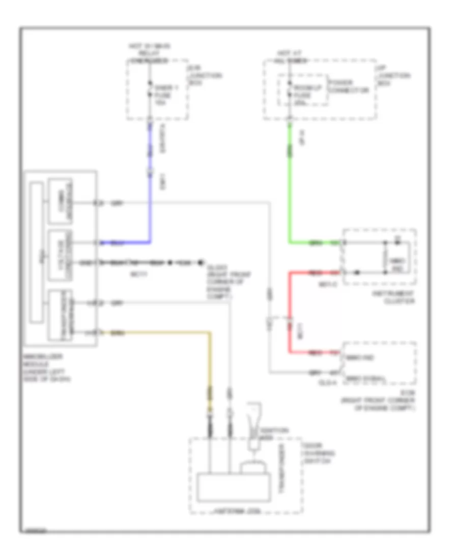
Immobilizer Wiring Diagram, without Smart Key System for Hyundai Veracruz Limited 2012
 https://portal-diagnostov.com/license.html
Automotive Electricians Portal FZCO
Automotive Electricians Portal FZCO
https://portal-diagnostov.com/license.html
https://portal-diagnostov.com/license.html
Automotive Electricians Portal FZCO
Automotive Electricians Portal FZCOList of elements for Immobilizer Wiring Diagram, without Smart Key System for Hyundai Veracruz Limited 2012:
- (+)
- (-)
- Antenna coil
- Clg-a
- Comms interface
- Door warning switch
- E/r junction box
- E/r-frta
- Ecm (right front corner of engine compt)
- Em11
- Glg03 (right front corner of engine compt)
- Gnd
- Hot at all times
- Hot w/ main relay energized
- I/p junction box
- I/p-h
- Ignition key
- Immo ind
- Immo signal
- Immobilizer module (under left side of dash)
- Instrument cluster
- M01-c
- Mc11
- Nca
- Pcu
- Power connector
- Red
- Room lp fuse 15a
- Snsr 1 fuse 15a
- Transponder
- Transponder interface
- Voltage conditioning
BODY CONTROL MODULES
Body Control Modules Wiring Diagram for Hyundai Veracruz Limited 2012
 https://portal-diagnostov.com/license.html
Automotive Electricians Portal FZCO
Automotive Electricians Portal FZCO
https://portal-diagnostov.com/license.html
https://portal-diagnostov.com/license.html
Automotive Electricians Portal FZCO
Automotive Electricians Portal FZCOList of elements for Body Control Modules Wiring Diagram for Hyundai Veracruz Limited 2012:
- (drl)
- (left side of engine compt) ge01
- (under left side of dash) bcm
- Acc/on input
- Anti-theft system
- Atm cont fuse 10a
- Audio 2 fuse 10a
- Auto light gnd
- Auto light sensor & security indicator (auto light sensor: top left side of dash)
- Auto light signal
- Av tail
- Buzzer
- Can high
- Can low
- Cluster fuse 10a
- Code save
- Computer data lines system
- Cruise control system
- Defogger relay
- Defogger sw
- Defogger system
- Door locks system
- Door switch
- Driver buckle sensor
- Drl relay ctrl
- Em11
- Engine running sig
- Eps fuse 10a
- Exterior lights system
- External buzzer
- F rain sensor
- F53-a
- Flasher sound buzzer
- Foot lp
- Front fog lp relay
- Front fog lp sw
- Fuel doors system
- Gm01 (under left side of dash)
- Gm04 (under left side of dash)
- Ground
- Hazard sw
- Head lp relay (high)
- Head lp relay (low)
- Headlights system
- High beam ind
- Hood switch
- Horn rly ctrl
- Horns system
- Hot at all times
- Hot in acc or on
- Hot in on
- Hot in on or start
- I/p junction box
- I/p-g
- I/p-h
- I/p-k
- Instrument cluster
- Instrument cluster system
- Interior lights system
- J/c jm04 (behind right side of dash)
- J/c jm05 (under left end of dash)
- K line
- Key ill
- Key in sw
- L deicer
- Left turn sig lp
- Lin
- Lr power window up
- Lr pwr window down
- M01-b
- M01-c
- M04-a
- M04-b
- M04-c
- M04-d
- Memory power
- Mf41
- Nca
- O rain sensor
- O/s handle sw
- On input
- On/start input
- Parking brake sw
- Pnk
- Power conn- ector
- Power distribution system
- Power windows system
- Ptg open/close sw
- Pwr
- Pwr t/gate rly ctrl
- Rear pwr wdw lock
- Red
- Rf com (data)
- Rf receiver (behind right side of dash)
- Right turn sig lp
- Room lp
- Room lp fuse 15a
- Rr power window up
- Rr pwr window down
- Seat belt ind
- Security ind
- Security indicator
- Signal
- Smart key control module (under rear of center console)
- Sound systems
- Starting/charging system
- T/gate
- T/gate latch
- T/gate lock actuator
- T/gate lock open status
- T/gate open flash
- T/gate open status
- T/gate open sw
- Tail lp relay
- Tailgate,
- Transaxle range sw p
- Transmissions system
- Trunk,
- Trunk, tailgate, fuel doors system
- Vehicle spd sensor
- W/ pwr
- W/o power t/gate
- W/o pwr
- Warning systems
- Windshield defogger
- Wiper/washer system
COMPUTER DATA LINES
Computer Data Lines Wiring Diagram for Hyundai Veracruz Limited 2012
 https://portal-diagnostov.com/license.html
Automotive Electricians Portal FZCO
Automotive Electricians Portal FZCO
https://portal-diagnostov.com/license.html
https://portal-diagnostov.com/license.html
Automotive Electricians Portal FZCO
Automotive Electricians Portal FZCOList of elements for Computer Data Lines Wiring Diagram for Hyundai Veracruz Limited 2012:
- (behind center of dash) joint connector jm01
- (center of dash)
- (left rear of engine compt) abs control module
- (not used)
- (right front corner of engine compartment) ecm
- (top of transaxle) tcm
- (under left end of dash) ge02
- (under left side of dash) gm01
- (w/o amp) audio
- 4wd ecm (behind right end of dash)
- A05-a
- Abs
- Bcm (under left side of dash)
- Can hi
- Can lo
- Clg-a
- Code
- D03-b
- D14-b
- Data link connector (lower left end of dash)
- Digital clock
- E/r junction box
- E/r-clg
- E/r-frtb
- Ecu 1 fuse 10a
- Em11
- Em31
- Esc
- Esc control module (left rear of engine compt)
- F06-b
- F19-b
- F53-a
- Fd11
- Fd12
- Front a/c control module (auto a/c)
- Fs01
- Hot at all times
- I/p junction box
- I/p-h
- I/p-j
- I/p-m
- Ims control module (under driver's seat)
- Instrument cluster
- Jbl amp (w/ amp) (behind left quarterpanel)
- Joint connector je01
- Joint connector jf02 (under center console)
- K line
- M01-b
- M04-b
- M04-c
- M05-a
- M05-b
- M07-b
- M80-c1
- Mf11
- Mf21
- Mf51
- Mf61
- Mts module (center of dash)
- Multipurpose check connector (at e/r junction box)
- Nca
- Pnk
- Power connector
- Power tail gate control module (behind left quarterpanel)
- Power window main switch
- Red
- Resister
- Right front power window switch
- Room lp fuse 15a
- S38-c
- Smart key control module (under rear of center console)
- Srs control module
- Tilt & telescopic module (on steering column)
- Tire pressure monitoring module
- Vss
COOLING FAN
Cooling Fan Wiring Diagram for Hyundai Veracruz Limited 2012
 https://portal-diagnostov.com/license.html
Automotive Electricians Portal FZCO
Automotive Electricians Portal FZCO
https://portal-diagnostov.com/license.html
https://portal-diagnostov.com/license.html
Automotive Electricians Portal FZCO
Automotive Electricians Portal FZCOList of elements for Cooling Fan Wiring Diagram for Hyundai Veracruz Limited 2012:
- A/c output signal
- A/c rly ctrl
- A/c sw on in
- Air conditioning system
- C/fan fusible link 40a
- Clg-a
- Clg-b
- Condenser fan motor (right side of radiator)
- Condenser fan relay 1
- Condenser fan relay 2
- E/r junction box
- E/r sub box
- E/r-clg
- E/r-frta
- E/r-frtb
- Ec21
- Ecm (right front corner of engine compt)
- Ecu fusible link 30a
- Engine coolant temperature sensor (at rear of engine)
- Fan rly ctrl (hi)
- Fan rly ctrl (lo)
- Glg05 (right front of engine compt)
- Ground
- Hot at all times
- Main relay
- Main rly ctrl
- Nca
- R/fan fusible link 40a
- Radiator fan motor (at front of engine compt)
- Radiator fan relay
- Red
- Signal
- Snsr 3 fuse 10a
CRUISE CONTROL
Cruise Control Wiring Diagram for Hyundai Veracruz Limited 2012
 https://portal-diagnostov.com/license.html
Automotive Electricians Portal FZCO
Automotive Electricians Portal FZCO
https://portal-diagnostov.com/license.html
https://portal-diagnostov.com/license.html
Automotive Electricians Portal FZCO
Automotive Electricians Portal FZCOList of elements for Cruise Control Wiring Diagram for Hyundai Veracruz Limited 2012:
- (+)
- (-)
- Abs
- Abs control module (left rear of engine compt)
- Accelerator pedal position sensor (top of accelerator pedal assembly)
- Aps 1 gnd
- Aps 1 power
- Aps 1 sig
- Aps 2 gnd
- Aps 2 power
- Aps 2 sig
- Brake lamp
- Brake switch
- Can transceiver
- Can- cel
- Can-high
- Can-low
- Clg-a
- Clg-b
- Clock spring
- Cluster fuse 10a
- Coast set
- Computer data lines system
- Cruise fuse 10a
- Cruise ind
- Cruise main
- Cruise set ind
- Cruise sw
- E/r junction box
- E/r-clg
- E/r-frtb
- Ecm (right front corner of engine compt)
- Ecu 1 fuse 10a
- Ecu 3 fuse 10a
- Esc
- Esc control module (left rear of engine compt)
- Etc motor & throttle position sensor (on throttle body)
- Etc motor +
- Etc motor -
- Exterior lights system
- Glg03 (right front corner of engine compt)
- Gnd
- Hot at all times
- Hot in on or start
- I/p junction box
- I/p-g
- I/p-j
- I/p-k
- Ill
- Instrument cluster
- Interior lights system
- M02-r
- Mc11
- Memory power
- Micom
- Mo1-b
- Mo1-c
- Multi- function switch
- Nca
- On/start input
- Pnk
- Red
- Resume/ accel
- Right cruise remocon switch
- Sensor ground
- Sound system
- Steering wheel
- Stop lamp switch (above brake pedal, on bracket)
- Stop lp fuse 15a
- Tcu 2 fuse 10a
- Tps 1 gnd
- Tps 1 pwr
- Tps 1 sig
- Tps 2 gnd
- Tps 2 pwr
- Tps 2 sig
- Vehicle spd in
DEFOGGERS
Defoggers Wiring Diagram for Hyundai Veracruz Limited 2012
 https://portal-diagnostov.com/license.html
Automotive Electricians Portal FZCO
Automotive Electricians Portal FZCO
https://portal-diagnostov.com/license.html
https://portal-diagnostov.com/license.html
Automotive Electricians Portal FZCO
Automotive Electricians Portal FZCOList of elements for Defoggers Wiring Diagram for Hyundai Veracruz Limited 2012:
- "c" pillar)
- Automatic a/c
- Bcm (under left side of dash)
- Def rly ctrl
- Def sw input
- Defogger
- Defogger switch
- Deicer fuse 15a
- E/r junction box
- E/r-frta
- Eng running input sig
- Engine compt)
- Fd11
- Fd12
- Fr11
- Fr31
- Front a/c control module (center of dash)
- Ge03 (left rear of
- Gf03 (behind left kick panel)
- Gf06 (behind right kick panel)
- Gf08 (base of left
- Gm01 (under left side of dash)
- Hot at all times
- I/p b+ 2 fusible link 50a
- I/p junction box
- I/p-a
- I/p-b
- I/p-c
- I/p-e
- I/p-f
- I/p-h
- I/p-j
- Ind
- Joint connector jd01 (in left front door)
- L deicer
- Left power outside mirror motor & defogger (at mirror)
- M04-b
- M04-d
- M05-a
- M06-a
- Manual a/c
- Mirr htd fuse 10a
- Nca
- R14
- R16
- Rear defogger relay
- Rear window defogger
- Red
- Right power outside mirror motor & defogger (at mirror)
- Rr htd fusible link 40a
- Starting/ charging system
- Windshield def rly ctrl
- Windshield defogger (base of left side windshield)
- Windshield defogger relay
ENGINE PERFORMANCE
3.8L
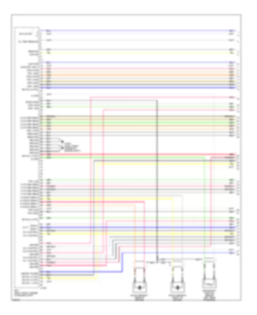
3.8L, Engine Performance Wiring Diagram (1 of 5) for Hyundai Veracruz Limited 2012
 https://portal-diagnostov.com/license.html
Automotive Electricians Portal FZCO
Automotive Electricians Portal FZCO
https://portal-diagnostov.com/license.html
https://portal-diagnostov.com/license.html
Automotive Electricians Portal FZCO
Automotive Electricians Portal FZCOList of elements for 3.8L, Engine Performance Wiring Diagram (1 of 5) for Hyundai Veracruz Limited 2012:
- (+)
- (-)
- Bank 1
- Bank 2
- Clg-b
- Cps 1 gnd
- Cps 1 pwr
- Cps 1 sig
- Cps 2 gnd
- Cps 2 pwr
- Cps 2 sig
- Crankshaft position sensor (left rear of engine)
- Cvvt
- Ecm (right front corner of engine compt)
- Etc motor
- Glg03 (right front corner of engine compt)
- Ground
- Heater
- Hi cps
- Hi knock sens 1
- Hi knock sens 2
- Hi oxygen sens
- Ign coil 1 ctrl
- Ign coil 2 ctrl
- Ign coil 3 ctrl
- Ign coil 4 ctrl
- Ign coil 5 ctrl
- Ign coil 6 ctrl
- Inj 1 control
- Inj 2 control
- Inj 3 control
- Inj 4 control
- Inj 5 control
- Inj 6 control
- Knock sensor 1 (rear of engine)
- Knock sensor 2 (front of engine)
- Lo cps
- Lo knock sens 1
- Lo knock sens 2
- Lo oxygen sens
- Map pwr
- Map sig
- Memory power
- Nca
- Oil temp sens sig
- On/start input
- Pnk
- Red
- Sens gnd
- Sens sig
- Shield gnd
- Tps 1 gnd
- Tps 1 pwr
- Tps 1 sig
- Tps 2 gnd
- Tps 2 pwr
- Tps 2 sig
3.8L, Engine Performance Wiring Diagram (2 of 5) for Hyundai Veracruz Limited 2012
 https://portal-diagnostov.com/license.html
Automotive Electricians Portal FZCO
Automotive Electricians Portal FZCO
https://portal-diagnostov.com/license.html
https://portal-diagnostov.com/license.html
Automotive Electricians Portal FZCO
Automotive Electricians Portal FZCOList of elements for 3.8L, Engine Performance Wiring Diagram (2 of 5) for Hyundai Veracruz Limited 2012:
- (rear of engine) manifold absolute pressure sensor
- (rear of engine) oil temperature sensor
- (top of engine)
- Camshaft position sensor 1 (rear of engine)
- Camshaft position sensor 2 (rear of engine)
- Clg18-1
- Clg18-3
- Clg18-5
- Clg24-1
- Clg24-2
- Clg24-3
- Clg24-4
- Clg24-5
- Clg24-6
- Clgig
- Clginj
- Engine coolant temperature sensor (at rear of engine)
- Etc motor & throttle position sensor (on throttle body)
- Ignition coil 1
- Ignition coil 3
- Ignition coil 5
- Injectors (top of engine)
- Nca
- Pnk
- Red
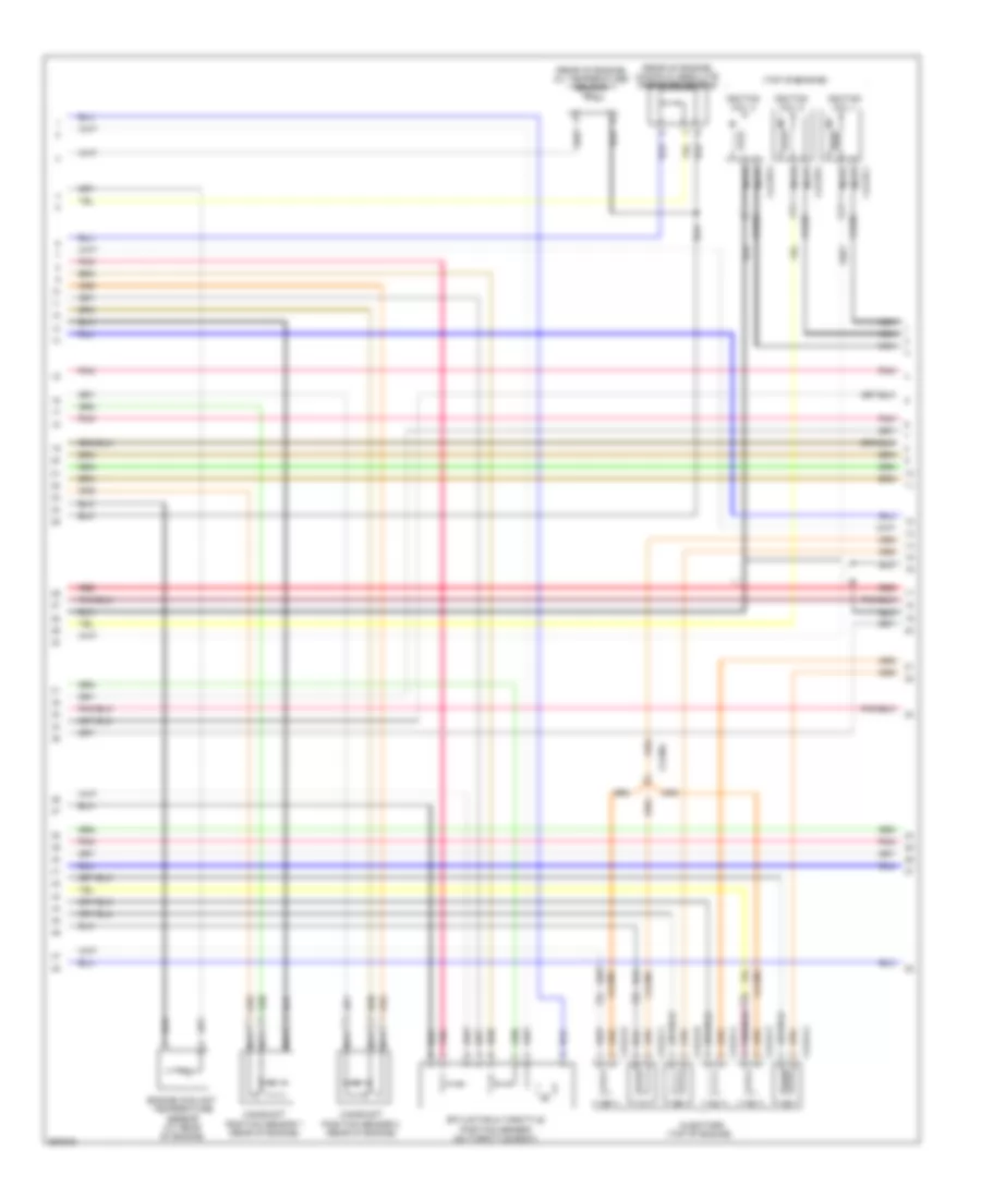
3.8L, Engine Performance Wiring Diagram (3 of 5) for Hyundai Veracruz Limited 2012
 https://portal-diagnostov.com/license.html
Automotive Electricians Portal FZCO
Automotive Electricians Portal FZCO
https://portal-diagnostov.com/license.html
https://portal-diagnostov.com/license.html
Automotive Electricians Portal FZCO
Automotive Electricians Portal FZCOList of elements for 3.8L, Engine Performance Wiring Diagram (3 of 5) for Hyundai Veracruz Limited 2012:
- (top of engine)
- Clg18-2
- Clg18-4
- Clg18-6
- Clgig
- Condenser (top front of engine)
- E/r junction box
- E/r-clg
- E/r-frta
- Ecu 1 fuse 10a
- Ecu 2 fuse 10a
- Ecu 3 fuse 10a
- Ecu fusible link 30a
- F/pump fuse 20a
- Fuel pump relay
- Glg03 (right front corner of engine compt)
- Glg04 (top of engine)
- Hot at all times
- Hot in or or start
- Ign coil fuse 20a
- Ignition coil 2
- Ignition coil 4
- Ignition coil 6
- Main relay
- Nca
- Pnk
- Red
- Snsr 1 fuse 15a
- Snsr 2 fuse 15a
- Snsr 3 fuse 10a
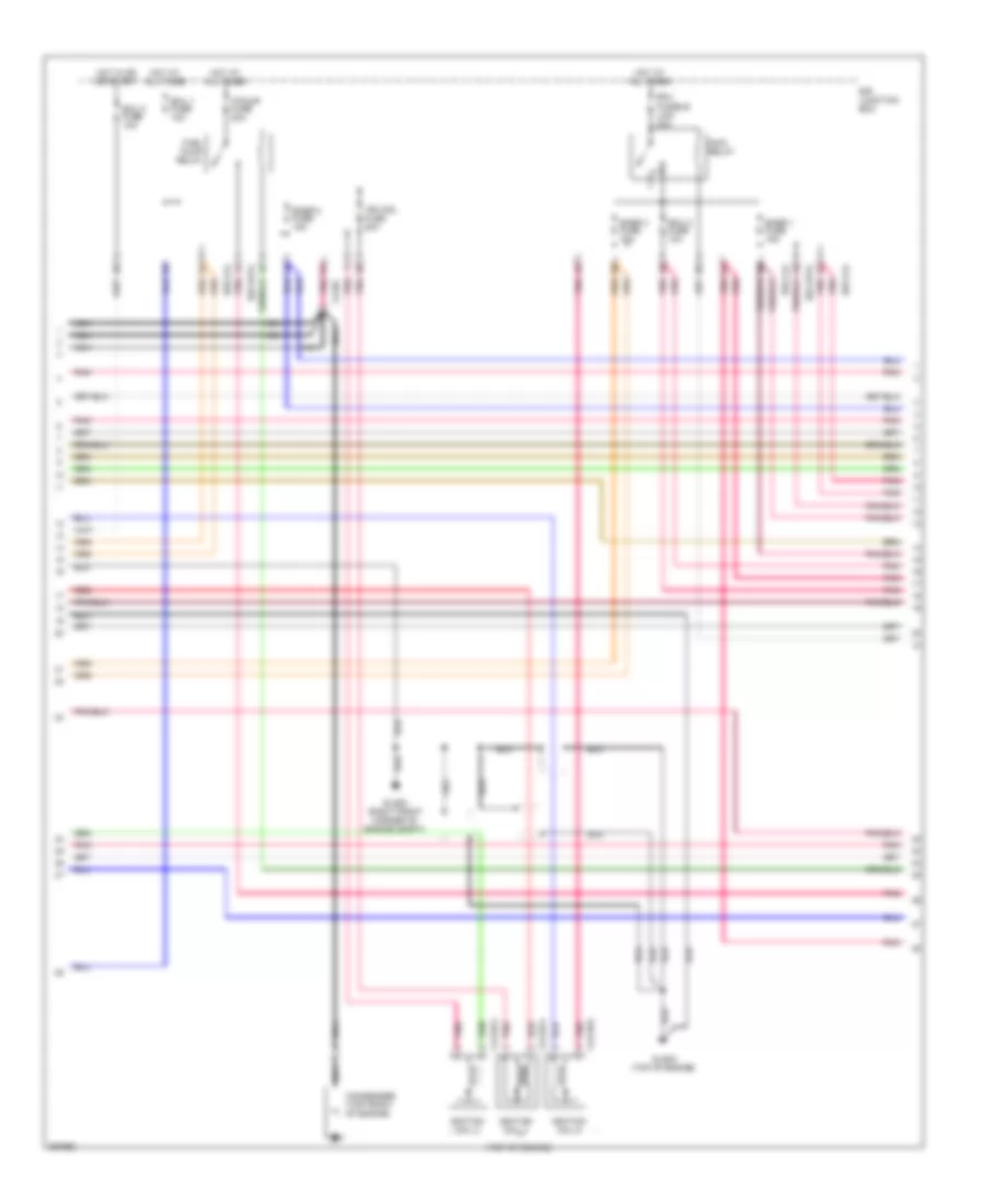
3.8L, Engine Performance Wiring Diagram (4 of 5) for Hyundai Veracruz Limited 2012
 https://portal-diagnostov.com/license.html
Automotive Electricians Portal FZCO
Automotive Electricians Portal FZCO
https://portal-diagnostov.com/license.html
https://portal-diagnostov.com/license.html
Automotive Electricians Portal FZCO
Automotive Electricians Portal FZCOList of elements for 3.8L, Engine Performance Wiring Diagram (4 of 5) for Hyundai Veracruz Limited 2012:
- (front center of engine, under intake) oil control valve 1
- (front center of engine, under intake) oil control valve 2
- (front of engine) oxygen sensor 2 (b2/s1)
- (left rear of engine) oxygen sensor 4 (b2/s2)
- (right front of engine) oxygen sensor 1 (b1/s1)
- (right front of engine) oxygen sensor 3 (b1/s2)
- (under center of vehicle) canister close valve
- Afs
- Ats
- Clg98-1
- Clg98-2
- Clgocv
- Cluster fuse 10a
- Computer data lines system
- Cruise ind
- Cruise set ind
- E53-a
- Ef11
- Fuel sender
- Fuel sender & fuel pump motor (inside fuel tank, beneath rear seat)
- Gauge sender
- Gf08 (base of left "c" pillar)
- Glg03 (right front corner of engine compt)
- Hot at all times
- Hot in on or start
- I/p junction box
- I/p-h
- I/p-k
- Immo ind
- Immobilizer module (under left side of dash)
- Instrument cluster
- M01-a
- M01-b
- M01-c
- Mass air flow sensor (on air intake)
- Mc11
- Mc31
- Mf11
- Mf21
- Mf41
- Mf51
- Micom
- Mil ind
- Nca
- Pnk
- Power connector
- Red
- Room lp fuse 15a
- Smart key control module (under rear of center console)
- W/ smart key
- W/o smart key
3.8L, Engine Performance Wiring Diagram (5 of 5) for Hyundai Veracruz Limited 2012
 https://portal-diagnostov.com/license.html
Automotive Electricians Portal FZCO
Automotive Electricians Portal FZCO
https://portal-diagnostov.com/license.html
https://portal-diagnostov.com/license.html
Automotive Electricians Portal FZCO
Automotive Electricians Portal FZCOList of elements for 3.8L, Engine Performance Wiring Diagram (5 of 5) for Hyundai Veracruz Limited 2012:
- (above fuel tank, beneath rear seat) fuel tank pressure sensor
- (left front of engine compt) semi active engine mounting solenoid
- A/c output signal
- A/c pressure transducer (right rear of engine compt)
- A/c relay control
- A/c sw on in
- Accelerator pedal position sensor (top of accelerator pedal assembly)
- Afs
- Air conditioning system
- Analog fuel lvl in (middle)
- Analog fuel lvl in (total)
- Anti-lock brakes system
- Aps 1 ground
- Aps 1 power
- Aps 1 signal
- Aps 2 ground
- Aps 2 power
- Aps 2 signal
- Atm cont fuse 10a
- Ats
- Brake lamp
- Brake sw
- Can-high
- Can-low
- Ccv
- Clg-a
- Cluster fuse 10a
- Computer data lines system
- Cooling fans system
- Cruise control system
- Cruise sw
- E/r junction box
- E/r-clg
- E/r-frta
- Ecm (right front corner of engine compt)
- Eng in
- Eng spd
- Eng spd out (tacho)
- Exterior ligths system
- Fan relay control
- Fuel pump rly ctrl
- Generator
- Glg01 (right rear corner of engine compt)
- Gnd
- High
- Hot at all times
- Hot in on or start
- I/p junction box
- I/p-c
- I/p-g
- I/p-j
- Immo indicator control
- Immo sig
- Instrument cluster system
- Low
- Main rly ctrl
- Main rly on pwr
- Mc11
- Mc31
- Mc41
- Mf11
- Mf21
- Mil indicator control
- On/st
- Pcsv
- Pnk
- Power
- Power steering pressure sensor (right rear of engine compt)
- Pre- excitation resistor
- Purge control solenoid valve (rear of engine)
- Red
- Semi active engine mounting control module (behind center of dash)
- Sens gnd
- Sens gnd (cruise sw)
- Sens sig
- Signal
- Sol ctrl
- Starting/charging system
- Stop lamp switch (above brake pedal, on bracket)
- Stop lp fuse 15a
- Tcu 2 fuse 10a
- Tpms fuse 10a
- Variable intake manifold valve (right rear of engine compt)
- Veh spd in/ abs buffered wheel in ats ground
- Viv
- W/ immobilizer
- W/o immobilizer
EXTERIOR LIGHTS
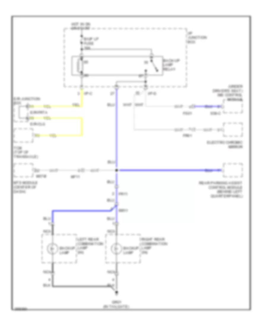
Backup Lamps Wiring Diagram for Hyundai Veracruz Limited 2012
 https://portal-diagnostov.com/license.html
Automotive Electricians Portal FZCO
Automotive Electricians Portal FZCO
https://portal-diagnostov.com/license.html
https://portal-diagnostov.com/license.html
Automotive Electricians Portal FZCO
Automotive Electricians Portal FZCOList of elements for Backup Lamps Wiring Diagram for Hyundai Veracruz Limited 2012:
- (under driver's seat) ims control module
- B/up lp fuse 10a
- Back-up lamp relay
- Backup lamp
- E/r junction box
- E/r-clg
- E/r-frta
- Electro chromic mirror
- Fr11
- Fr61
- Fs01
- Gr01 (in tailgate)
- Hot in on or start
- I/p junction box
- I/p-c
- I/p-d
- Left rear combination lamp (in)
- M07-b
- Mf11
- Mts module (center of dash)
- Nca
- Rear parking assist control module (behind left quarterpanel)
- Right rear combination lamp (in)
- Rr11
- S38-c
- Tcm (top of transaxle)
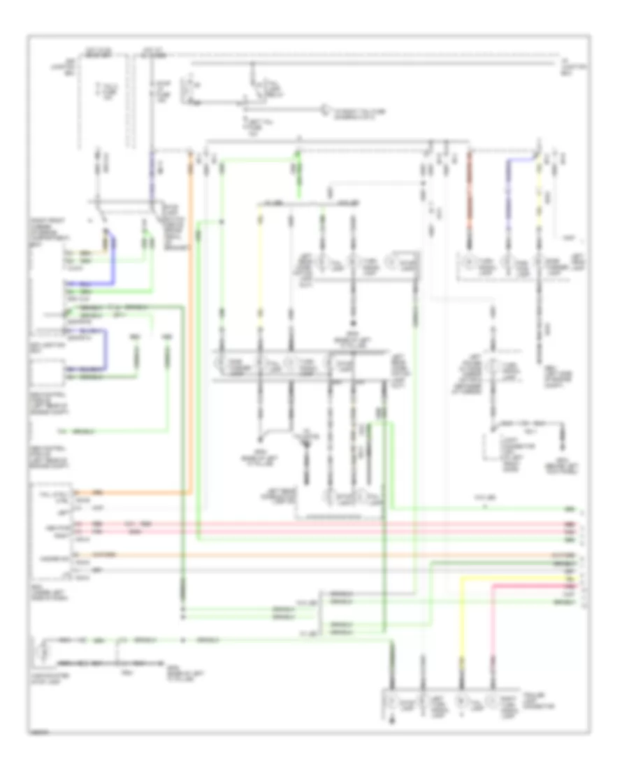
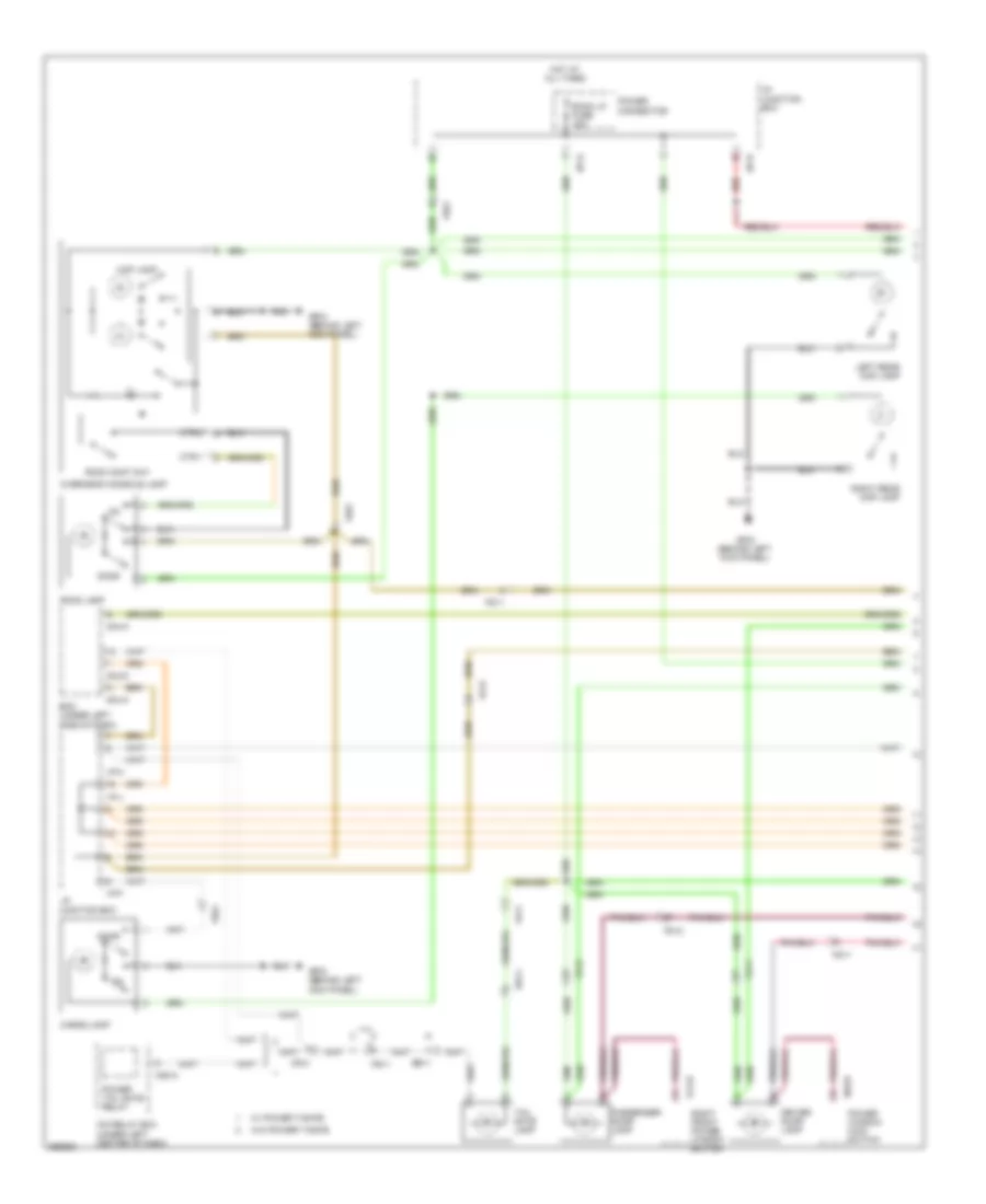
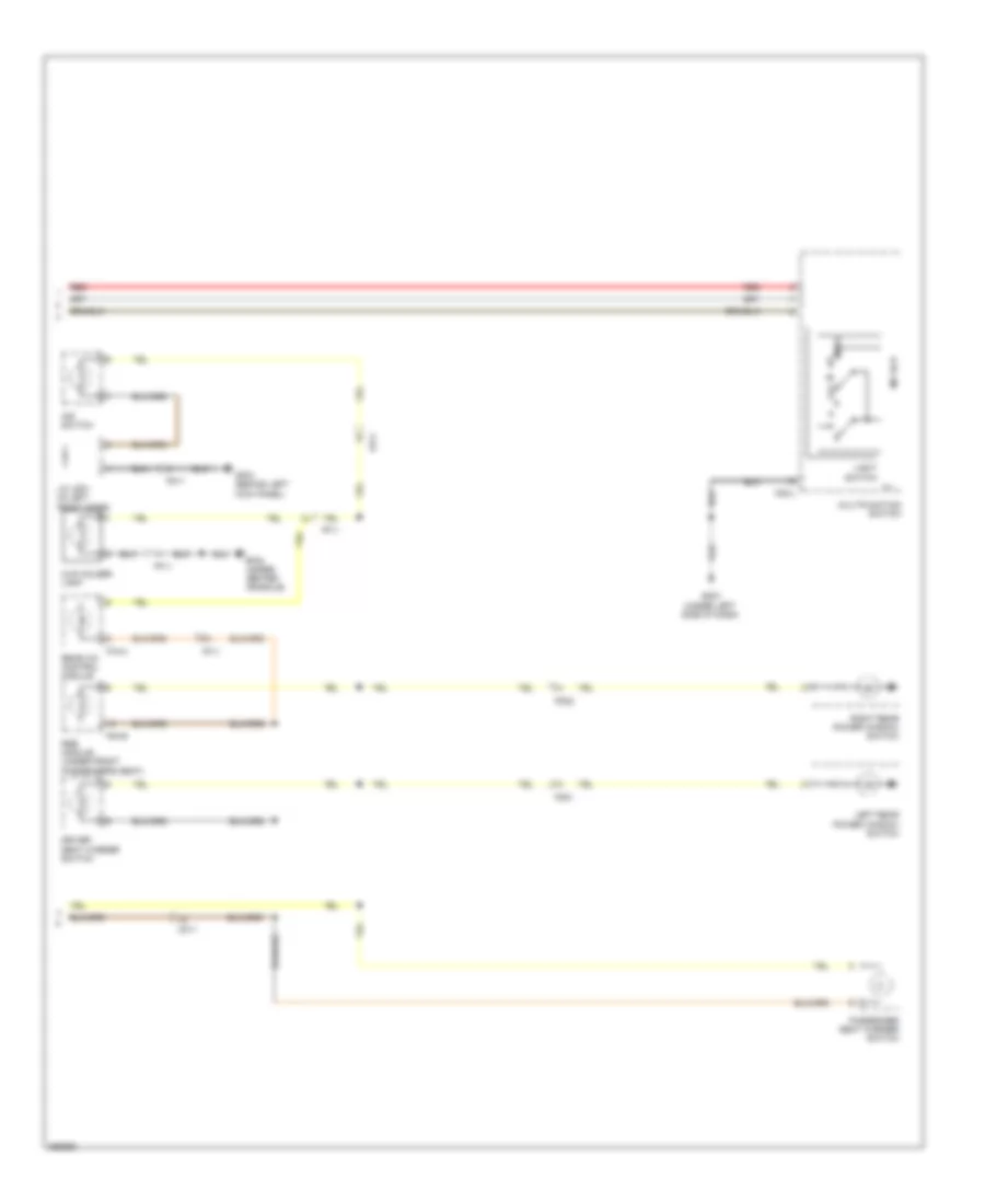
Exterior Lamps Wiring Diagram (1 of 2) for Hyundai Veracruz Limited 2012
 https://portal-diagnostov.com/license.html
Automotive Electricians Portal FZCO
Automotive Electricians Portal FZCO
https://portal-diagnostov.com/license.html
https://portal-diagnostov.com/license.html
Automotive Electricians Portal FZCO
Automotive Electricians Portal FZCOList of elements for Exterior Lamps Wiring Diagram (1 of 2) for Hyundai Veracruz Limited 2012:
- (in
- (right front corner of engine compartment) ecm
- Abs
- Abs control module (left rear of engine compt)
- Bcm (under left side of dash)
- Clg-a
- Ctrl
- E/r junction box
- E/r- clg
- E/r-clg
- E/r-frta
- E/r-frtb
- Ee31
- Ef11
- Em21
- Esc
- Esc control module (left rear of engine compt)
- Fd11
- Fr21
- Ge01 (left side of engine compt)
- Gf03 (behind left kick panel)
- Gf08 (base of left "c" pillar)
- Gnd nca
- Gr01
- Hazard sw
- High-mounted stop lamp
- Hot at all times
- Hot in on or start
- I/p junction box
- I/p-b
- I/p-c
- I/p-d
- I/p-j
- I/p-l
- Joint connector jd01 (in left front door)
- Left
- Left head lamp
- Left power outside mirror motor & defogger (at mirror)
- Left rear combi- nation lamp (out)
- Left rear combination lamp (in)
- Left tail fuse 10a
- Left turn signal lamp
- Lin
- M04-a
- M04-b
- M04-c
- M04-d
- Mc11
- Mem pwr
- Nca
- Par- king lamp
- Pnk
- Red
- Right
- Right turn signal lamp
- Rr11
- Side marker lamp
- Sig
- Stop lamp
- Stop lamp switch (above brake pedal, on bracket)
- Stop lp fuse 15a
- Tail lamp
- Tail lamp relay
- Tail lp rly
- Tailgate)
- Tcu 2 fuse 10a
- To right tail fuse (diagram 2 0f 2)
- Trailer lamp connector
- Turn signal lamp
- W/ led
- W/o led
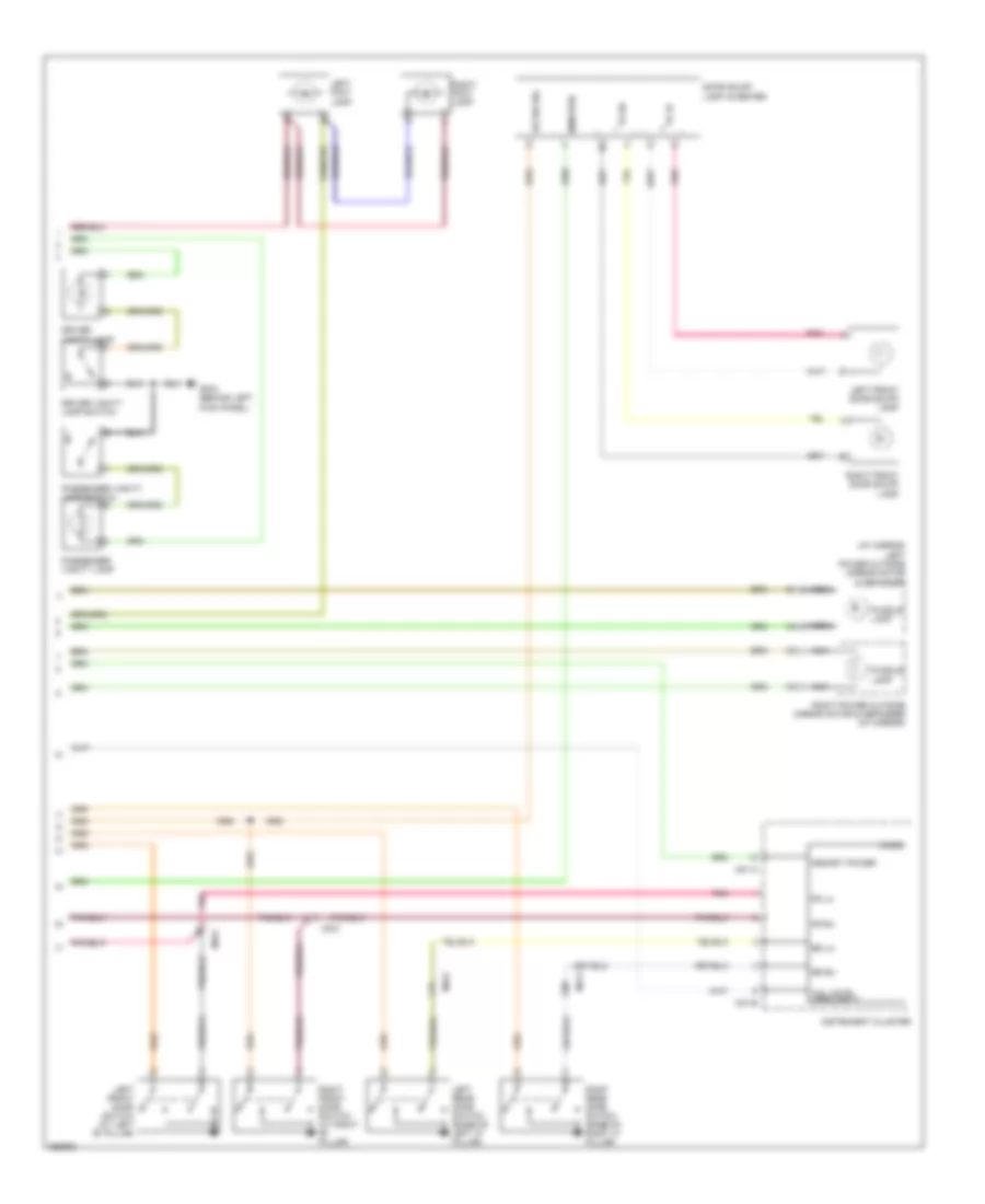
Exterior Lamps Wiring Diagram (2 of 2) for Hyundai Veracruz Limited 2012
 https://portal-diagnostov.com/license.html
Automotive Electricians Portal FZCO
Automotive Electricians Portal FZCO
https://portal-diagnostov.com/license.html
https://portal-diagnostov.com/license.html
Automotive Electricians Portal FZCO
Automotive Electricians Portal FZCOList of elements for Exterior Lamps Wiring Diagram (2 of 2) for Hyundai Veracruz Limited 2012:
- "c" pillar)
- (base of right
- (behind right side of dash)
- (in tailgate) gr01
- (under left
- Atm cont fuse 10a
- Auto
- Cf11
- E/r jun- ction box
- E/r sub box
- E/r-frta
- E/r-frtb
- Ec11
- Fd12
- Fr11
- Fr31
- Fr41
- From tail lamp relay (diagram 1 0f 2)
- Gf06 (behind right kick panel)
- Gf07
- Gf07 (base of right "c" pillar)
- Glg05 (right front of engine compt)
- Gm01 (under left side of dash)
- Gm04
- Gnd nca
- Gr01 (in tailgate)
- Hazard switch
- Hot at all times
- Hot in on or start
- I/p b+ 1 fusible link 50a
- I/p junction box
- I/p-d
- I/p-g
- I/p-h
- I/p-j
- I/p-l
- Ill
- Instrument cluster
- Interior lights system
- Joint connector jm04
- Left
- License lamp
- Light switch
- M/f ecu
- M01-a
- M01-b
- M01-c
- M02-l
- Mc11
- Multi-function switch
- Nca
- Off
- Par- king lamp
- Pnk
- Power connector
- Red
- Right
- Right head- lamp
- Right power outside mirror motor & defogger (at mirror)
- Right rear combi- nation lamp (in)
- Right rear combi- nation lamp (out)
- Right tail fuse 10a
- Right turn ind
- Room lp fuse 15a
- Rr11
- Rr21
- Side marker lamp
- Side of dash)
- Sig nca
- Stop lamp
- T/sig fuse 15a
- Tail lamp
- Tailgate handle switch
- Tailgate handle switch & license lamp
- Trailer fusible link 30a
- Trailer power outlet
- Trunk, tailgate, fuel doors system
- Turn ind left
- Turn signal lamp
- Turn signal lamp switch
- W/ led
- W/o led
- Wiper/washer system
GROUND DISTRIBUTION
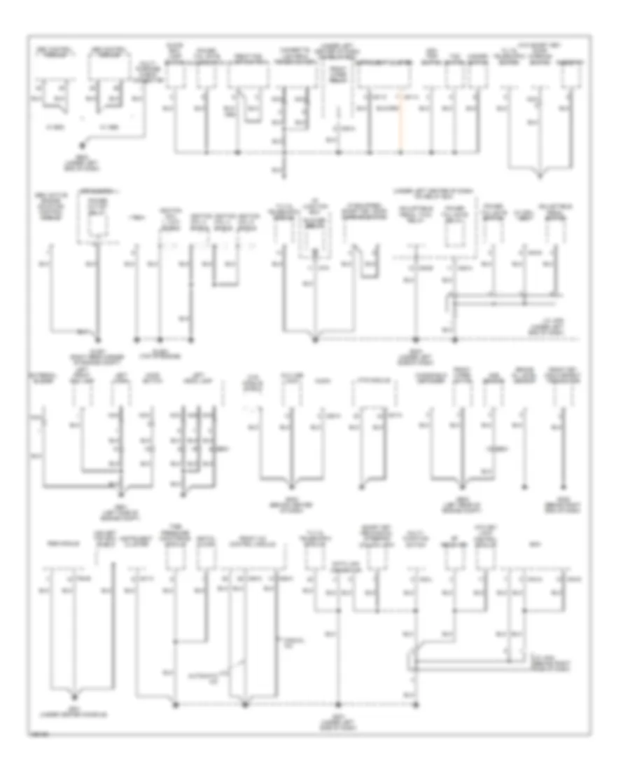
Ground Distribution Wiring Diagram (1 of 3) for Hyundai Veracruz Limited 2012
 https://portal-diagnostov.com/license.html
Automotive Electricians Portal FZCO
Automotive Electricians Portal FZCO
https://portal-diagnostov.com/license.html
https://portal-diagnostov.com/license.html
Automotive Electricians Portal FZCO
Automotive Electricians Portal FZCOList of elements for Ground Distribution Wiring Diagram (1 of 3) for Hyundai Veracruz Limited 2012:
- (if equipped) smart key door warning switch
- (under left center of dash) icm relay box
- (w/ drl) bcm
- (w/o smart key) door warning switch
- Abs control module
- Adjustable pedal switch
- Adjustable pedal twin relay
- Aqs sensor
- Atm key lock control module
- Audio
- Automatic a/c
- Aux usb jack
- Bcm
- Blower relay
- Brake oil level sensor
- Cigarette lighter & power outlet
- Data link connector
- Digital clock
- E/r sub box
- Ee31
- Esc control module
- External buzzer
- F54-b
- Front a/c control module
- Front fet (field effect transistor)
- Front fog lamp switch
- Front wiper motor
- Front wiper relay
- Ge01 (left side of engine compt)
- Ge02 (under left end of dash)
- Ge03 (left rear of engine compt)
- Gf01 (under center console)
- Glg01 (right rear corner of engine compt)
- Glg04 (top of engine)
- Glove box lamp switch
- Gm01 (under left side of dash)
- Gm03 (behind center of dash)
- Gm04 (under left side of dash)
- Gm05 (behind right end of dash)
- Hazard switch
- Hood switch
- I/p junction box
- I/p-k
- Ignition coil 1, 3 & 5 shield
- Ignition coil 2 shield
- Ignition coil 4 shield
- Ignition coil 6 shield
- Instrument cluster
- J/c jm04 (behind right side of dash)
- J/c jm05 (under left end of dash)
- Left front fog lamp
- Left head lamp
- Left horn
- M01-a
- M01-c
- M02-l
- M04-a
- M04-d
- M05-a
- M06-a
- M07-a
- M08-a
- M08-b
- M80-a
- Manual a/c
- Mts module
- Mts module shield
- Multi- function switch
- Multi- purpose check connector
- Nca
- Odo trip switch
- Power outlet relay
- Power tail gate glove switch
- Power tail gate relay
- Power tail gate switch
- Rf receiver
- Rheostat
- Rse module
- Semi active engine mounting control module
- Smart key mechanical steering column lock
- Tcm
- Tilt & telescopic module
- Tilt & telescopic switch
- Tire pressure monitoring module
- Tod switch
- Usa set top box shield
- W/ abs
- W/ esc
- Windshield defogger
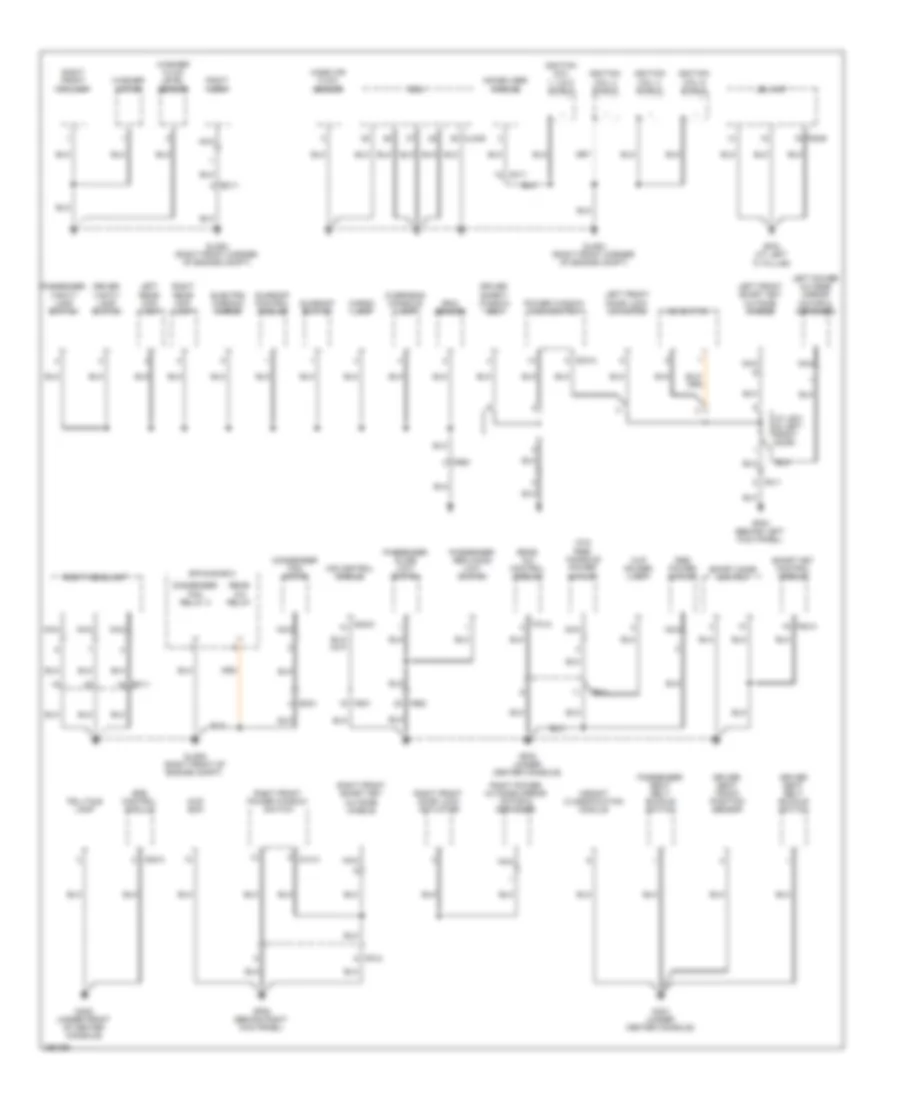
Ground Distribution Wiring Diagram (2 of 3) for Hyundai Veracruz Limited 2012
 https://portal-diagnostov.com/license.html
Automotive Electricians Portal FZCO
Automotive Electricians Portal FZCO
https://portal-diagnostov.com/license.html
https://portal-diagnostov.com/license.html
Automotive Electricians Portal FZCO
Automotive Electricians Portal FZCOList of elements for Ground Distribution Wiring Diagram (2 of 3) for Hyundai Veracruz Limited 2012:
- (w/o rse) console power outlet
- 4wd ecm
- A05-a
- Cargo lamp
- Clg-b
- Condenser fan motor
- Condenser fan relay 2
- Cup holder lamp
- D03-a
- D14-a
- Driver safety window ecm
- Driver seat belt buckle switch
- Driver seat track position sensor
- Driver vanity lamp switch
- E/r sub box
- Ec11
- Ec21
- Ecm
- Electro chromic mirror
- F06-b
- F53-a
- F70-a
- Fd11
- Fd12
- Ff11
- Fr61
- Fs01
- Fs02
- Ga01 (under center console)
- Ga02 (under front of center console)
- Gf02 (under center console)
- Gf03 (behind left kick panel)
- Gf04 (at left "c" pillar)
- Gf06 (behind right kick panel)
- Glg02 (right front corner of engine compt)
- Glg03 (right front corner of engine compt)
- Glg05 (right front of engine compt)
- Ignition coil 1, 3 & 5 shield
- Ignition coil 2 shield
- Ignition coil 4 shield
- Ignition coil 6 shield
- Immobilizer module
- Ims control module
- Ims switch
- J/c jd01 (in left front door)
- Jbl amp
- Left front door lock actuator
- Left front smart key outside handle
- Left power outside mirror motor & defogger
- Left rear map lamp
- Mass air flow sensor
- Mc11
- Nca
- Overhead console lamp
- Passenger reclining limit switch
- Passenger seat belt buckle switch
- Passenger slide limit switch
- Passenger vanity lamp switch
- Power window main switch
- Rain sensor
- Rear a/c control module
- Rear a/c relay
- Right front door lock actuator
- Right front fog lamp
- Right front power window switch
- Right front smart key outside handle
- Right headlamp
- Right horn
- Right power outside mirror motor & defogger
- Right rear map lamp
- Rse power outlet
- S38-d
- Smart key control module
- Sport mode switch
- Srs control module
- Sunroof control module
- Sunroof switch
- Telltale lamp
- Washer fluid level sensor
- Washer motor
- Weight classification module
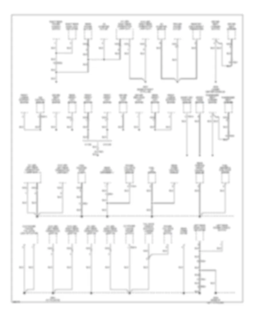
Ground Distribution Wiring Diagram (3 of 3) for Hyundai Veracruz Limited 2012
 https://portal-diagnostov.com/license.html
Automotive Electricians Portal FZCO
Automotive Electricians Portal FZCO
https://portal-diagnostov.com/license.html
https://portal-diagnostov.com/license.html
Automotive Electricians Portal FZCO
Automotive Electricians Portal FZCOList of elements for Ground Distribution Wiring Diagram (3 of 3) for Hyundai Veracruz Limited 2012:
- (w/ led) left rear combination lamp (in)
- (w/ led) left rear combination lamp (out)
- (w/ led) right rear combination lamp (in)
- (w/ led) right rear combination lamp (out)
- (w/ power t/gate) power latch 1
- (w/o led) left rear combination lamp (in)
- (w/o led) left rear combination lamp (out)
- (w/o led) right rear combination lamp (in)
- (w/o led) right rear combination lamp (out)
- (w/o power t/gate) tail gate lock actuator
- Ac inverter module
- Ac inverter outlet
- Driver reclining limit switch
- Driver seat manual switch
- Driver seat warmer
- Driver seat warmer switch
- Driver slide limit switch
- F19-a
- F53-a
- Fd21
- Fd22
- Fr21
- Fr31
- Fr41
- Front height limit switch
- Front lumbar support switch
- Fs01
- Fs02
- Fuel lid motor
- Fuel sender & fuel pump motor
- Gf05 (under center console)
- Gf07 (base of right "c" pillar)
- Gf08 (base of left "c" pillar)
- Gr01 (in tailgate)
- High mounted stop lamp
- Ims control module
- Left rear door lock actuator
- Left rear power window switch
- Nca
- Passenger seat warmer
- Passenger seat warmer switch
- Power tail gate control module
- Power tail gate on/off switch
- R02-a
- Rear fet (field effect transistor)
- Rear height limit switch
- Rear parking assist control module
- Rear power outlet
- Rear window defogger (-)
- Rear wiper control module
- Rear wiper motor
- Right rear door lock actuator
- Right rear power window switch
- Rr21
- S38-a
- Smart key control module
- Sport mode switch
- Tail gate handle switch & license lamp
- Trailer power outlet
- W/ ims
- W/o ims
HEADLIGHTS
Headlights Wiring Diagram (1 of 2) for Hyundai Veracruz Limited 2012
 https://portal-diagnostov.com/license.html
Automotive Electricians Portal FZCO
Automotive Electricians Portal FZCO
https://portal-diagnostov.com/license.html
https://portal-diagnostov.com/license.html
Automotive Electricians Portal FZCO
Automotive Electricians Portal FZCOList of elements for Headlights Wiring Diagram (1 of 2) for Hyundai Veracruz Limited 2012:
- (top left
- Auto light sensor
- Auto light sensor & security indicator
- Auto lt sens gnd
- Auto lt sens sig
- Auto lt sens sply
- Bcm (under left side of dash)
- Drl rly ctrl
- E/r junction box
- E/r sub box
- E/r-clg
- E/r-frta
- E/r-frtb
- Ec11
- Ee31
- Em21
- Em31
- Frt fog lp rly
- Frt fog lp sw
- Ge01 (left side of engine compartment)
- Glg05 (right front of engine compartment)
- Gm04 (under left side of dash)
- H/lp hi fuse 20a
- H/lp lo lh fuse 15a
- H/lp lo rh fuse 15a
- Head lamp (high) relay
- Head lp (high) rly
- Head lp (low) rly
- Hi beam ind
- High beam ind
- Hot at all times
- Instrument cluster
- Left head lamp (low) relay
- Left headlamp
- Lin
- M01-c
- M04-a
- M04-b
- M04-c
- M04-d
- Mc31
- Nca
- Pnk
- Red
- Right head lamp (low) relay
- Right head- lamp
- Side of dash)
- T/sig fuse 15a
- Tail lp rly ctrl
Headlights Wiring Diagram (2 of 2) for Hyundai Veracruz Limited 2012
 https://portal-diagnostov.com/license.html
Automotive Electricians Portal FZCO
Automotive Electricians Portal FZCO
https://portal-diagnostov.com/license.html
https://portal-diagnostov.com/license.html
Automotive Electricians Portal FZCO
Automotive Electricians Portal FZCOList of elements for Headlights Wiring Diagram (2 of 2) for Hyundai Veracruz Limited 2012:
- Atm cont fuse 10a
- Auto
- Dim
- Dimmer/ passing switch
- Drl fuse 15a
- Drl relay
- Drl resistor (left side of engine compartment)
- E/r junction box
- E/r-clg
- E/r-frta
- E/r-frtb
- Em21
- Em31
- Fr fog fuse 15a
- Front fog lamp relay
- Front fog lamp switch
- Ge01 (left side of engine compartment)
- Glg02 (right front corner of engine compartment)
- Gm01 (under left side of dash)
- Gm04 (under left side of dash)
- Hot at all times
- Hot in on or start
- I/p junction box
- I/p-c
- I/p-g
- I/p-h
- I/p-j
- Icm relay box (under left center of dash)
- Ill
- Ind
- Interior lights system
- Left front fog lamp
- Left tail fuse 10a
- Light switch
- M/f ecm
- M02-l
- M08-a
- Multifunction switch
- Off
- Off auto
- Pass
- Pnk
- Power connector
- Red
- Right front fog lamp
- Room lp fuse 15a
- Tail lamp relay
- Wiper/washer system
HORN
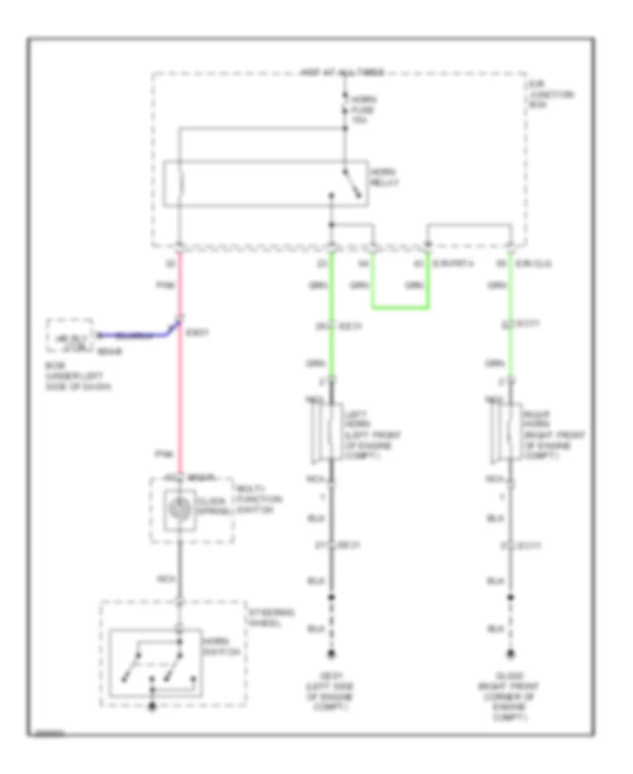
Horn Wiring Diagram for Hyundai Veracruz Limited 2012
 https://portal-diagnostov.com/license.html
Automotive Electricians Portal FZCO
Automotive Electricians Portal FZCO
https://portal-diagnostov.com/license.html
https://portal-diagnostov.com/license.html
Automotive Electricians Portal FZCO
Automotive Electricians Portal FZCOList of elements for Horn Wiring Diagram for Hyundai Veracruz Limited 2012:
- (left front of engine compt)
- (right front of engine compt)
- Bcm (under left side of dash)
- Clock spring
- E/r junction box
- E/r-clg
- E/r-frta
- Ec11
- Ee31
- Em31
- Ge01 (left side of engine compt)
- Glg02 (right front corner of engine compt)
- Horn fuse 15a
- Horn relay
- Horn switch
- Hot at all times
- Hr rly ctrl m04-b
- Left horn
- M02-r
- Multi- function switch
- Nca
- Pnk
- Right horn
- Steering wheel
INSTRUMENT CLUSTER
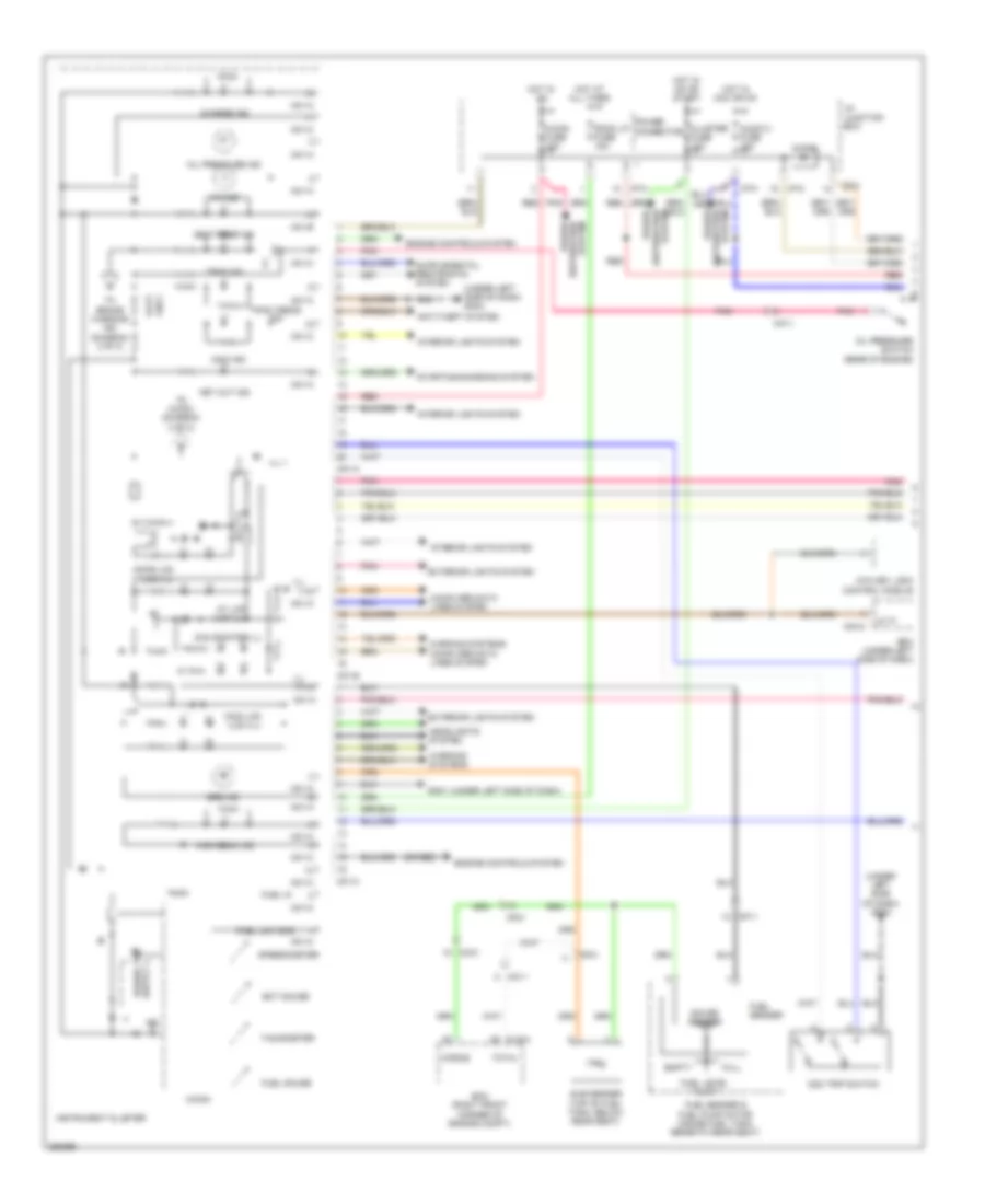
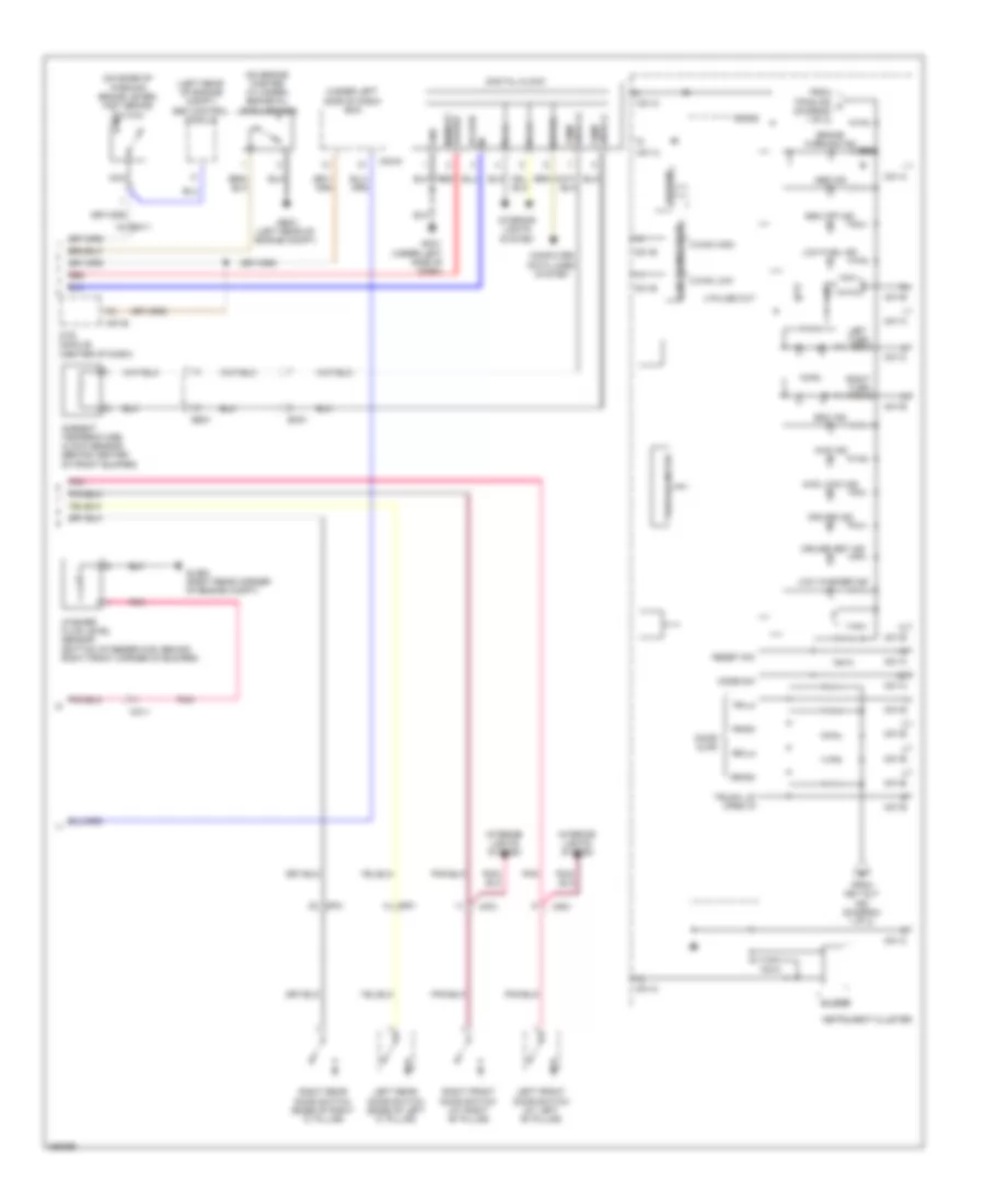
Instrument Cluster Wiring Diagram (1 of 2) for Hyundai Veracruz Limited 2012
 https://portal-diagnostov.com/license.html
Automotive Electricians Portal FZCO
Automotive Electricians Portal FZCO
https://portal-diagnostov.com/license.html
https://portal-diagnostov.com/license.html
Automotive Electricians Portal FZCO
Automotive Electricians Portal FZCOList of elements for Instrument Cluster Wiring Diagram (1 of 2) for Hyundai Veracruz Limited 2012:
- (or red)
- (under left side of dash)
- (under left side of dash) gm04
- A/con fuse 10a
- Anti-theft system
- At lcd (lcd ill)
- At p
- Atm key lock control module
- Audio 2 fuse 10a
- Bcm (under left side of dash)
- Charge ind
- Clg-a
- Cluster fuse 10a
- Computer data lines system
- Dial/pointer ill
- Diode
- Distribution power
- Distribution system
- Door lcd (lcd ill)
- Ecm (right front corner of engine compt)
- Ect gauge
- Empty
- Engine controls system
- Exterior lights system
- Fuel gauge
- Fuel in
- Fuel level float
- Fuel low gnd
- Fuel sender
- Fuel sender & fuel pump motor (inside fuel tank, beneath rear seat)
- Full
- Gauge sender
- Gm01
- Headlights system
- High beam ind
- Hot at all times
- Hot in acc or on
- Hot in on
- Hot in on or start
- I/p junction box
- I/p-c
- I/p-h
- I/p-k
- Ign
- Ill (+)
- Ill (-)
- Ill +
- Immo ind
- Instrument cluster
- Interior lights system
- Key out ind
- M01-a
- M01-b
- M01-c
- M04-c
- Main lcd (lcd ill)
- Mc11
- Mc31
- Mf11
- Mf21
- Mf41
- Micom
- Middle
- Mil ind
- Odo trip switch
- Oil pressure ind
- Oil pressure switch (rear of engine)
- Patt only
- Pnk
- Power
- Power connector
- Red
- Room lp fuse 15a
- Seat belt ind
- Speedometer
- Srs ind
- Starting/charging system
- Sub sender (top of fuel tank, below rear seat)
- System
- Tachometer
- To brake warning ind (diagram 2 of 2)
- To micom (diagram 2 of 2)
- Total
- Tpms ind
- Tpms tread ind
- Warning systems
Instrument Cluster Wiring Diagram (2 of 2) for Hyundai Veracruz Limited 2012
 https://portal-diagnostov.com/license.html
Automotive Electricians Portal FZCO
Automotive Electricians Portal FZCO
https://portal-diagnostov.com/license.html
https://portal-diagnostov.com/license.html
Automotive Electricians Portal FZCO
Automotive Electricians Portal FZCOList of elements for Instrument Cluster Wiring Diagram (2 of 2) for Hyundai Veracruz Limited 2012:
- (left rear of engine compt) esc control module
- (on base of parking brake lever) foot brake switch
- (on brake master cylinder) brake oil level sensor
- (under left side of dash) bcm
- 4 pulse out
- 4wd ind
- 4wd lock ind
- Abs ind
- Acc/on in
- Ambient temperature clock sensor (behind center of front bumper)
- Brake warning ind
- Buzzer
- C-can high
- C-can low
- Can transceiver
- Computer data lines system
- Cruise ind
- Cruise set ind
- Digital clock
- Door ajar
- Ebd
- Ee31
- Eeprom
- Em11
- Em21
- Esc ind
- Esc off ind
- Fr-lh
- Fr-rh
- From key out ind (diagram 1 of 2)
- From tpms ind a (diagram 1 of 2)
- Ge03 (left rear of engine compt)
- Glg02 (right rear corner of engine compt)
- Gm01 (under left side of dash)
- Gnd
- Ill (+)
- Ill (-)
- Instrument cluster
- Interior lights system
- Left front door switch (at left "b" pillar)
- Left rear door switch (base of left "c" pillar)
- Left turn ind
- Low fuel ind
- Low washer ind
- M01-a
- M01-b
- M01-c
- M04-d
- M07-b
- Mc11
- Memory power
- Mf21
- Mf61
- Micom
- Mode sw
- Mts module (center of dash)
- Nca
- Pnk
- Red
- Reset sw
- Right front door switch (at right "b" pillar)
- Right rear door switch (base of right "c" pillar)
- Right turn ind
- Rr-lh
- Rr-rh
- Snsr (+) temp
- Snsr (-) temp
- Speed
- Trip/odo meter
- Trunk lid open in
- Washer fluid level sensor (bottom of reservoir, behind right front corner of bumper)
INTERIOR LIGHTS
Courtesy Lamps Wiring Diagram (1 of 2) for Hyundai Veracruz Limited 2012
 https://portal-diagnostov.com/license.html
Automotive Electricians Portal FZCO
Automotive Electricians Portal FZCO
https://portal-diagnostov.com/license.html
https://portal-diagnostov.com/license.html
Automotive Electricians Portal FZCO
Automotive Electricians Portal FZCOList of elements for Courtesy Lamps Wiring Diagram (1 of 2) for Hyundai Veracruz Limited 2012:
- Bcm (under left side of dash)
- Cargo lamp
- Ctr-1
- Ctr-2
- D03-b
- D14-b
- Door
- Driver door lamp
- Fd11
- Fd12
- Fr11
- Fr61
- Gf03 (behind left kick panel)
- Hot at all times
- I/p junction box
- I/p-e
- I/p-f
- I/p-h
- I/p-j
- Icm relay box (under left center of dash)
- Left rear map lamp
- M04-a
- M04-d
- M08-a
- Map lamp
- Mf41
- Overhead console lamp
- Passenger door lamp
- Power connector
- Power tail gate relay
- Power window main switch
- Red
- Right front power window switch
- Right rear map lamp
- Room cont s/w
- Room lamp
- Room lp fuse 15a
- Rr11
- Tail gate lamp
- W/ power t/gate
- W/o power t/gate
Courtesy Lamps Wiring Diagram (2 of 2) for Hyundai Veracruz Limited 2012
 https://portal-diagnostov.com/license.html
Automotive Electricians Portal FZCO
Automotive Electricians Portal FZCO
https://portal-diagnostov.com/license.html
https://portal-diagnostov.com/license.html
Automotive Electricians Portal FZCO
Automotive Electricians Portal FZCOList of elements for Courtesy Lamps Wiring Diagram (2 of 2) for Hyundai Veracruz Limited 2012:
- (at mirror) left power outside mirror motor & defogger
- Door scuff lamp inverter
- Dr sw sig
- Driver vanity lamp
- Driver vanity lamp switch
- Fr lh
- Fr rh
- Gf03 (behind left kick panel)
- Instrument cluster
- Left foot lamp
- Left front door scuff lamp
- Left front door switch (at left "b" pillar)
- Left rear door switch (base of left "c" pillar)
- M01-b
- M01-c
- Mem pwr
- Memory power
- Mf21
- Mf61
- Micom
- Nca
- Passenger vanity lamp
- Passenger vanity lamp switch
- Pnk
- Puddle lamp
- Right foot lamp
- Right front door scuff lamp
- Right front door switch (at right "b" pillar)
- Right power outside mirror motor & defogger (at mirror)
- Right rear door switch (base of right "c" pillar)
- Rr lh
- Rr rh
- Tail gate open input
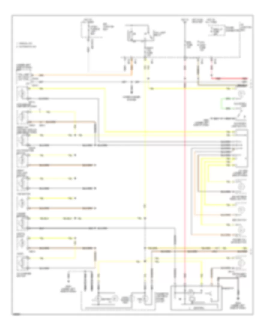
Instrument Illumination Wiring Diagram (1 of 2) for Hyundai Veracruz Limited 2012
 https://portal-diagnostov.com/license.html
Automotive Electricians Portal FZCO
Automotive Electricians Portal FZCO
https://portal-diagnostov.com/license.html
https://portal-diagnostov.com/license.html
Automotive Electricians Portal FZCO
Automotive Electricians Portal FZCOList of elements for Instrument Illumination Wiring Diagram (1 of 2) for Hyundai Veracruz Limited 2012:
- (under left side of dash) bcm
- Ac inverter switch
- Adjustable pedal switch
- Ashtray ill
- Atm cont fuse 10a
- Audio
- Automatic a/c
- Cigarette lighter & power outlet
- Control
- Digital clock
- E/r junction box
- E/r-frta
- Eps fuse 10a
- Esc switch
- Front a/c control module (center of dash)
- Front fog lamp switch
- Glove box lamp
- Glove box lamp switch
- Gm04 (under left side of dash)
- Hand- phone tray
- Hazard switch
- Hot at all times
- Hot in on
- Hot in on or start
- I/p b+1 fusible link 50a
- I/p junction box
- I/p-b
- I/p-g
- I/p-h
- I/p-j
- I/p-l
- Ill
- Instrument cluster
- J/c jm02 (under left end of dash)
- Lin
- M01-a
- M02-r
- M04-b
- M04-c
- M05-a
- M06-a
- M07-a
- M80-a
- Manual a/c
- Mf41
- Mts module (center of dash)
- Multifunction switch
- Nca
- Power connector
- Power tail gate switch
- Red
- Rheostat
- Right tail fuse 10a
- Room lp fuse 15a
- Tail lamp relay
- Tail lamp rly auto cut ctrl
- Tgs ill
- Tod switch
- Wiper/washer system
Instrument Illumination Wiring Diagram (2 of 2) for Hyundai Veracruz Limited 2012
 https://portal-diagnostov.com/license.html
Automotive Electricians Portal FZCO
Automotive Electricians Portal FZCO
https://portal-diagnostov.com/license.html
https://portal-diagnostov.com/license.html
Automotive Electricians Portal FZCO
Automotive Electricians Portal FZCOList of elements for Instrument Illumination Wiring Diagram (2 of 2) for Hyundai Veracruz Limited 2012:
- Auto
- Cup holder lamp
- Driver seat warmer switch
- F54-b
- F70-a
- Fd11
- Fd21
- Fd22
- Ff11
- Gf02 (under center console)
- Gf03 (behind left kick panel)
- Gm01 (under left side of dash)
- Ims switch
- J/c jd01 (in left front door)
- Left rear power window switch
- Light switch
- M/f ecu
- M02-l
- Mf11
- Multifunction switch
- Off
- Passenger seat warmer switch
- Rear a/c control module
- Red
- Right rear power window switch
- Rse module (under front passenger's seat)
MEMORY SYSTEMS
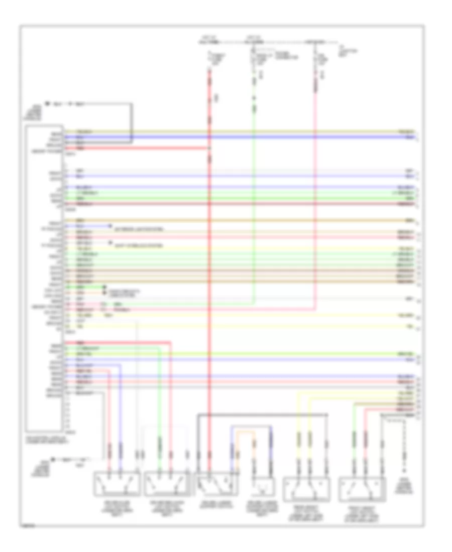
Driver"s Memory Seat Wiring Diagram (1 of 2) for Hyundai Veracruz Limited 2012
 https://portal-diagnostov.com/license.html
Automotive Electricians Portal FZCO
Automotive Electricians Portal FZCO
https://portal-diagnostov.com/license.html
https://portal-diagnostov.com/license.html
Automotive Electricians Portal FZCO
Automotive Electricians Portal FZCOList of elements for Driver"s Memory Seat Wiring Diagram (1 of 2) for Hyundai Veracruz Limited 2012:
- "p" pos sig
- "r" pos sig
- Can high
- Can low
- Computer data lines system
- Down
- Driver lumbar support motor (under driver's seat)
- Driver lumbar support switch
- Driver reclining limit switch (under driver's seat)
- Driver slide limit switch (under driver's seat)
- Exterior lights system
- Front
- Front height limit switch (under left side of driver's seat)
- Fs01
- Gf02 (under center console)
- Gf05 (under center console)
- Ground
- Hot at all times
- Hot in on
- I/p junction box
- I/p-d
- I/p-e
- Ims control module (under driver's seat)
- Ims fuse 10a
- Memory power
- Nca
- On input
- P/seat fuse 30a
- Pnk
- Power connector
- Rear
- Rear height limit switch (under left side of driver's seat)
- Red
- Room lp fuse 15a
- S38-a
- S38-b
- S38-c
- S38-d
- Shift interlock system
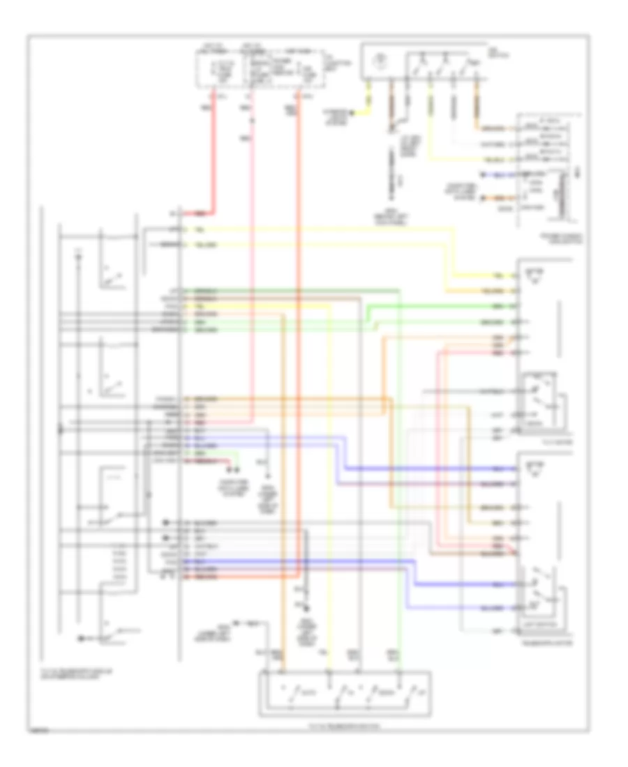
Driver"s Memory Seat Wiring Diagram (2 of 2) for Hyundai Veracruz Limited 2012
 https://portal-diagnostov.com/license.html
Automotive Electricians Portal FZCO
Automotive Electricians Portal FZCO
https://portal-diagnostov.com/license.html
https://portal-diagnostov.com/license.html
Automotive Electricians Portal FZCO
Automotive Electricians Portal FZCOList of elements for Driver"s Memory Seat Wiring Diagram (2 of 2) for Hyundai Veracruz Limited 2012:
- +5va
- Can high
- Can low
- Computer data
- D03-b
- Driver reclining motor (under driver's seat)
- Driver seat manual switch
- Driver slide motor (under driver's seat)
- Fd11
- Front height adjuster motor (under driver's seat)
- Front height adjuster switch
- Gf03 (behind left kick panel)
- Ill
- Ims switch
- Interior lights system
- J/c jd01 (in left front door)
- J/c js01 (under driver's seat)
- Lines system
- Mcu
- Nca
- Power window main switch
- Rear height adjuster motor (under driver's seat)
- Rear height adjuster switch
- Reclining switch
- Set
- Slide switch
- Transceiver ic can
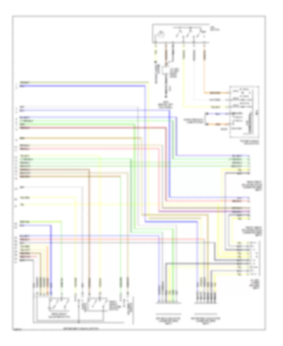
Memory Power Tilt & Power Telescopic Wiring Diagram for Hyundai Veracruz Limited 2012
 https://portal-diagnostov.com/license.html
Automotive Electricians Portal FZCO
Automotive Electricians Portal FZCO
https://portal-diagnostov.com/license.html
https://portal-diagnostov.com/license.html
Automotive Electricians Portal FZCO
Automotive Electricians Portal FZCOList of elements for Memory Power Tilt & Power Telescopic Wiring Diagram for Hyundai Veracruz Limited 2012:
- +5va
- Auto
- Back
- Back(s2)
- Can high
- Can low
- Can transceiver ic
- Computer data lines system
- D03-b
- Down
- Down(s2)
- Fd11
- Fwd
- Fwd(s1)
- Gf03 (behind left kick panel)
- Gm01 (under left side of dash)
- Gm04 (under left side of dash)
- Gnd
- Hot at all times
- Hot in on
- I/p junction box
- I/p-h
- I/p-j
- Ill
- Ims fuse 10a
- Ims switch
- Interior lights system
- J/c jd01 (in left front door)
- Limit switch
- Mcu
- Motor
- Out
- Power con- nector
- Power window main switch
- Red
- Room lp fuse 15a
- Set
- Telescopic motor
- Tilt & tele fuse 15a
- Tilt & telescopic module (on steering column)
- Tilt & telescopic switch
- Tilt motor
- Up(s1)
- Vcc
NAVIGATION
Navigation Wiring Diagram (1 of 2) for Hyundai Veracruz Limited 2012
 https://portal-diagnostov.com/license.html
Automotive Electricians Portal FZCO
Automotive Electricians Portal FZCO
https://portal-diagnostov.com/license.html
https://portal-diagnostov.com/license.html
Automotive Electricians Portal FZCO
Automotive Electricians Portal FZCOList of elements for Navigation Wiring Diagram (1 of 2) for Hyundai Veracruz Limited 2012:
- (+)
- (-)
- (behind center
- (center of dash)
- Acc/on in
- Alt l
- Antenna
- Audio 1 fuse 15a
- Audio 2 fuse 10a
- Audio common
- Audio l
- Audio r
- Auto light
- Av tail
- Bcm (under left side of dash)
- Can high
- Can high 1
- Can low
- Can low 1
- Cdma
- Cdma antenna
- Circuit
- Clock spring
- Computer data lines system
- Eq select
- Exterior lights system
- F/cable
- Feeder cable
- Fl (+)
- Fl (-)
- Fr (+)
- Fr (-)
- Gf01 (under center console)
- Gm03
- Gm03 (behind center of dash)
- Gnd
- Gps
- Gps antenna
- Ground
- Hot at all times
- Hot in acc or on
- I/p junction box
- I/p-g
- I/p-k
- Ill
- Ill (+)
- Ill (-)
- Instrument cluster system
- Interior lights system
- Left audio remocon switch
- M02-r
- M04-b
- M07-a
- M07-b
- Memory power
- Memory pwr
- Mf31
- Mf51
- Mf91
- Micro antenna
- Mode
- Mts module
- Multifunction switch
- Mute
- Nca
- Of dash)
- Parking break
- Power connector
- Radio
- Radio antenna
- Red
- Remocon gnd
- Remocon sig
- Remote amp
- Reverse sig
- Rl (+)
- Rl (-)
- Rr (+)
- Rr (-)
- Seek down
- Seek up
- Speed
- Starting/charging system
- Steering wheel
- Surr on/off
- Tv antenna
- Usa set top box
- Vol down
- Vol up
- W/ audio remocon
- Xm sdars common
- Xm sdars left
- Xm sdars right
Navigation Wiring Diagram (2 of 2) for Hyundai Veracruz Limited 2012
 https://portal-diagnostov.com/license.html
Automotive Electricians Portal FZCO
Automotive Electricians Portal FZCO
https://portal-diagnostov.com/license.html
https://portal-diagnostov.com/license.html
Automotive Electricians Portal FZCO
Automotive Electricians Portal FZCOList of elements for Navigation Wiring Diagram (2 of 2) for Hyundai Veracruz Limited 2012:
- (+)
- (-)
- Amp fuse 30a
- Center speaker
- Cf11
- Computer data lines system
- E/r sub box
- Eq sel
- F06-a
- F06-b
- Fd11
- Fd12
- Fd21
- Fd22
- Ff51
- Fl (+)
- Fl (-)
- Fr (+)
- Fr (-)
- Fr41
- Frt ctr (+)
- Frt ctr (-)
- Gf04 (at left "c" pillar)
- Ground
- Hot at all times
- Jbl amp (behind left quarterpanel)
- Left front door speaker
- Left front tweeter speaker
- Left rear door speaker
- Left tail gate speaker
- Lh twtr (+)
- Lh twtr (-)
- Mem power
- Mf11
- Mf21
- Mf41
- Nca
- Re on/off
- Red
- Rh twtr (+)
- Rh twtr (-)
- Right front door speaker
- Right front tweeter speaker
- Right rear door speaker
- Right tail gate speaker
- Rl (+)
- Rl (-)
- Rr (+)
- Rr (-)
- Sub wfr l (+)
- Sub wfr l (-)
- Sub wfr r (+)
- Sub wfr r (-)
- Sub woofer speaker
- Surr on/off
- Tgat lh (+)
- Tgat lh (-)
- Tgat rh (+)
- Tgat rh (-)
- Vss
Parking Assistant Wiring Diagram for Hyundai Veracruz Limited 2012
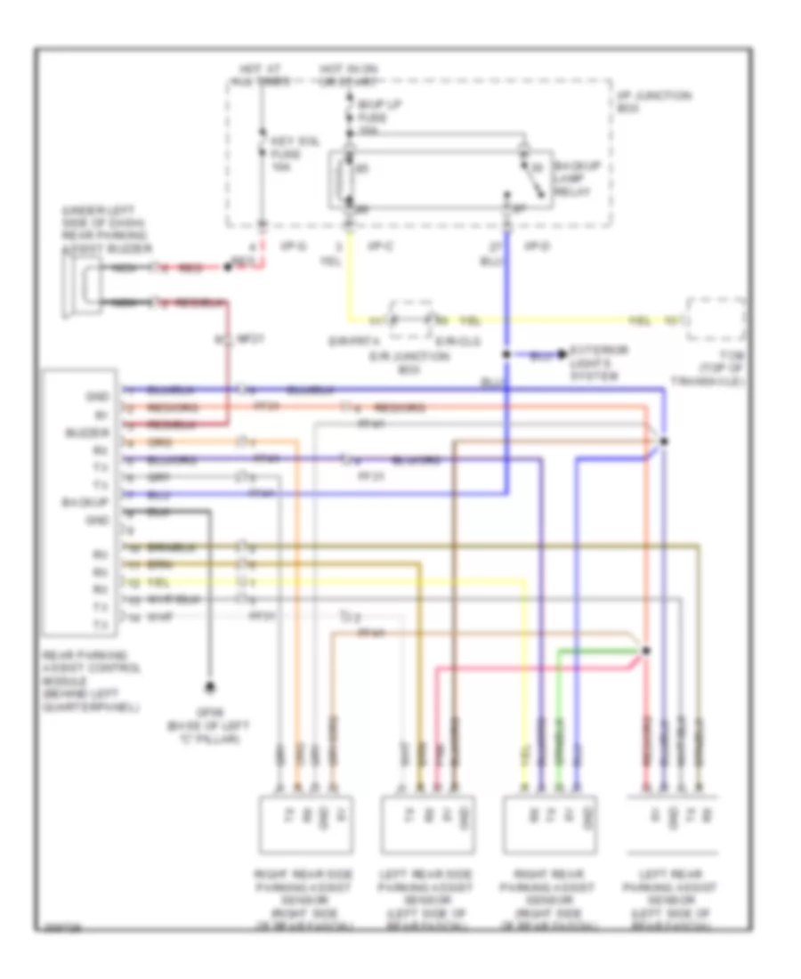 https://portal-diagnostov.com/license.html
Automotive Electricians Portal FZCO
Automotive Electricians Portal FZCO
https://portal-diagnostov.com/license.html
https://portal-diagnostov.com/license.html
Automotive Electricians Portal FZCO
Automotive Electricians Portal FZCOList of elements for Parking Assistant Wiring Diagram for Hyundai Veracruz Limited 2012:
- (under left side of dash) rear parking assist buzzer
- B/up lp fuse 10a
- Backup
- Backup lamp relay
- Buzzer
- E/r junction box
- E/r-clg
- E/r-frta
- Exterior lights system
- Ff31
- Ff41
- Gf08 (base of left "c" pillar)
- Gnd
- Hot at all times
- Hot in on or start
- I/p junction box
- I/p-c
- I/p-d
- I/p-g
- Key sol fuse 10a
- Left rear parking assist sensor (left side of rear fascia)
- Left rear side parking assist sensor (left side of rear fascia)
- Mf21
- Nca
- Pnk
- Rear parking assist control module (behind left quarterpanel)
- Red
- Right rear parking assist sensor (right side of rear fascia)
- Right rear side parking assist sensor (right side of rear fascia)
- Tcm (top of transaxle)
POWER DISTRIBUTION
Power Distribution Wiring Diagram (1 of 9) for Hyundai Veracruz Limited 2012
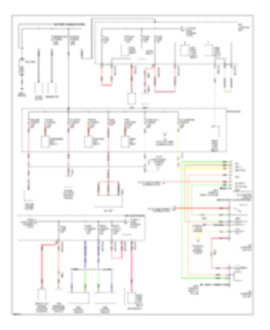 https://portal-diagnostov.com/license.html
Automotive Electricians Portal FZCO
Automotive Electricians Portal FZCO
https://portal-diagnostov.com/license.html
https://portal-diagnostov.com/license.html
Automotive Electricians Portal FZCO
Automotive Electricians Portal FZCOList of elements for Power Distribution Wiring Diagram (1 of 9) for Hyundai Veracruz Limited 2012:
- 3 of 9)
- (diagram
- A/con fuse 10a
- A/con relay
- Abs 1 fusible link 40a
- Abs 2 fusible link 40a
- Abs control module
- Ac inverter fusible link 30a
- Ac inverter module (behind right quarterpanel)
- Ac inverter outlet
- Ac inverter switch
- Ac1
- Ac2
- Amp fuse 30a
- Battery
- Battery fusible link box
- Bcm
- Body ground
- C/fan fusible link 40a
- Cf11
- Condenser fan relay 1
- E/r junction box
- E/r sub box
- E/r-clg
- E/r-frta
- E/r-frtb
- Em11
- Em21
- Esc control module
- F/pump fuse 20a
- F06-b
- F19-a
- From a/con fuse a (diagram 1 of 9)
- Fuel pump relay
- Generator
- Generator fusible link 200a
- Gf07 (base of right "c" pillar)
- Gnd
- Head lamp (high) relay
- Ill
- Ind
- Ind (+)
- Interior lights system
- Ip box b+ 3 fusible link 40a
- Jbl amp
- Junction box
- Left head lamp (low) relay
- M04-a
- Mem pwr
- Mf51
- Nca
- On input
- P t/gate fusible link 30a
- Pnk
- Power tail gate control module
- R/fan fusible link 40a
- Radiator fan relay
- Rear a/c relay
- Red
- Right h/lp lo fuse 15a
- Right head lamp (low) relay
- Rr blower fuse 20a
- Semiactive engine mounting solenoid
- Start motor
- Sub box fusible link 125a
- Sw 'on' sig
- T/sig fuse 15a
- Tcm
- Tcu 1 fuse 15a
- Tire pressure monitoring module
- To digital clock (diagram 4 of 9)
- To ecu 1 fuse (diagram 2 of 9)
- To i/p
- To i/p junction box (diagram 6 of 9)
- To i/p junction box (diagram 8 of 9)
- To p/outlet fuse (diagram 9 of 9)
- To tpms fuse (diagram 1 of 9)
- Tpms fuse 10a
- Trailer fusible link 30a
- Trailer power outlet
- W/ abs
- W/ esc
Power Distribution Wiring Diagram (2 of 9) for Hyundai Veracruz Limited 2012
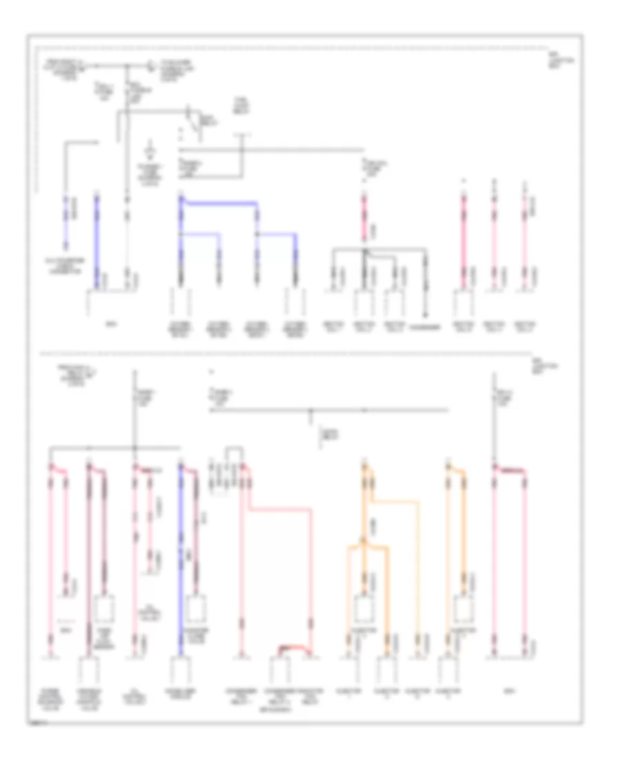 https://portal-diagnostov.com/license.html
Automotive Electricians Portal FZCO
Automotive Electricians Portal FZCO
https://portal-diagnostov.com/license.html
https://portal-diagnostov.com/license.html
Automotive Electricians Portal FZCO
Automotive Electricians Portal FZCOList of elements for Power Distribution Wiring Diagram (2 of 9) for Hyundai Veracruz Limited 2012:
- A/con relay
- Canister close valve
- Clg-a
- Clg-b
- Clg18-1
- Clg18-2
- Clg18-3
- Clg18-4
- Clg18-5
- Clg18-6
- Clg24-1
- Clg24-2
- Clg24-3
- Clg24-4
- Clg24-5
- Clg24-6
- Clg98-1
- Clg98-2
- Clgig
- Clginj
- Clgocv
- Condenser
- Condenser fan relay 1
- Condenser fan relay 2
- E/r junction box
- E/r sub box
- E/r-clg
- E/r-frta
- E/r-frtb
- Ecm
- Ecu 1 fuse 10a
- Ecu 2 fuse 10a
- Ecu fusible link 30a
- Ef11
- Em11
- From main relay c (diagram 2 of 9)
- From right h/lp lo fuse b (diagram 1 of 9)
- Fuel pump relay
- Ign coil fuse 20a
- Ignition coil 1
- Ignition coil 2
- Ignition coil 3
- Ignition coil 4
- Ignition coil 5
- Ignition coil 6
- Immobilizer module
- Injector
- Main relay
- Mass air flow sensor
- Multipurpose check connector
- Nca
- Oil control valve 1
- Oil control valve 2
- Oxygen sensor 1 (b1/s1)
- Oxygen sensor 2 (b2/s1)
- Oxygen sensor 3 (b1/s2)
- Oxygen sensor 4 (b2/s2)
- Pnk
- Purge control solenoid valve
- Radiator fan relay
- Red
- Snsr 1 fuse 15a
- Snsr 2 fuse 15a
- Snsr 3 fuse 10a
- To blower fusible link (diagram 3 of 9)
- To snsr 1 fuse (diagram 2 of 9)
- Variable intake manifold valve
Power Distribution Wiring Diagram (3 of 9) for Hyundai Veracruz Limited 2012
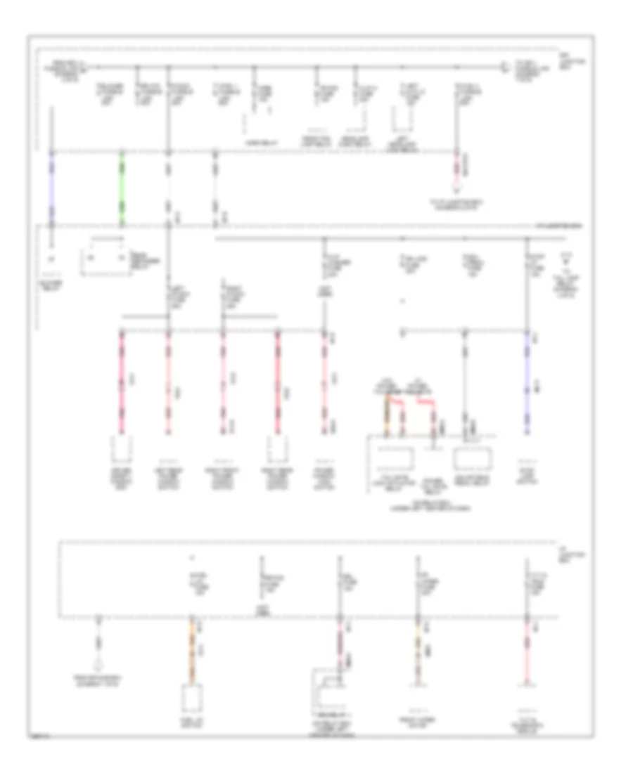 https://portal-diagnostov.com/license.html
Automotive Electricians Portal FZCO
Automotive Electricians Portal FZCO
https://portal-diagnostov.com/license.html
https://portal-diagnostov.com/license.html
Automotive Electricians Portal FZCO
Automotive Electricians Portal FZCOList of elements for Power Distribution Wiring Diagram (3 of 9) for Hyundai Veracruz Limited 2012:
- (not used)
- Adj- pedal fuse 15a
- Adjustable pedal relay
- Blower fusible link 40a
- Blower relay
- D03-a
- D14-a
- Dr lock fuse 20a
- Driver safety window ecm
- Drl fuse 15a
- Drl relay
- E/r junction box
- E/r-frta
- Em31
- Fd11
- Fd12
- Fd21
- Fd22
- Fr fog fuse 15a
- Fr wiper fuse 30a
- From e/r sub box (diagram 1 of 9)
- From ecu fusible link d (diagram 2 of 9)
- Front fog lamp relay
- Front wiper motor
- Fuel lid fuse 15a
- Fuel lid switch
- H/lp hi fuse 20a
- H/lp washer fuse 20a
- Headlamp (high) relay
- Horn fuse 15a
- Horn relay
- I/p b+ 1 fusible link 50a
- I/p b+ 2 fusible link 50a
- I/p junction box
- I/p-a
- I/p-b
- I/p-d
- I/p-e
- I/p-g
- I/p-j
- Icm relay box (under left center of dash)
- Left h/lp lo fuse 15a
- Left headlamp (low) relay
- Left p/wdw fuse 25a
- Left rear power window switch
- M08-a
- M08-b
- Mc11
- P/wdw fusible link 40a
- Pnk
- Power tail gate relay
- Power window main switch
- Rear defogger relay
- Red
- Right front power window switch
- Right p/wdw fuse 25a
- Right rear power window switch
- Rr fog fuse 15a
- Rr htd fusible link 40a
- Stop lamp switch
- Stop lp fuse 15a
- Tail gate lock actuator relay
- Tilt & tele fuse 15a
- Tilt & telescopic module
- To i/p junction box (diagram 5 of 9)
- To ign 1 fusible link (diagram 7 of 9)
- To tail lamp relay (diagram 4 of 9)
- W/ power tail gate
- W/o power tail gate
Power Distribution Wiring Diagram (4 of 9) for Hyundai Veracruz Limited 2012
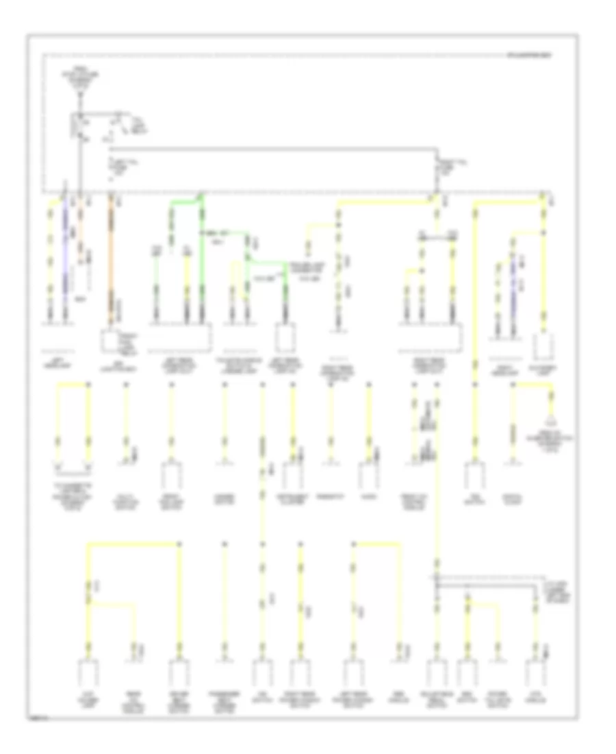 https://portal-diagnostov.com/license.html
Automotive Electricians Portal FZCO
Automotive Electricians Portal FZCO
https://portal-diagnostov.com/license.html
https://portal-diagnostov.com/license.html
Automotive Electricians Portal FZCO
Automotive Electricians Portal FZCOList of elements for Power Distribution Wiring Diagram (4 of 9) for Hyundai Veracruz Limited 2012:
- Adjustable pedal switch
- Audio
- Bcm
- Cup holder lamp
- Digital clock
- Driver seat warmer switch
- E/r junction box
- E/r-frta
- Ec11
- Em31
- Esc switch
- F54-b
- F70-a
- Fd11
- Fd21
- Fd22
- Ff11
- Fr11
- Fr31
- From ac inverter switch (diagram 1 of 9)
- From stop lp fuse (diagram 3 of 9)
- Front a/c control module
- Front fog lamp relay
- Front fog lamp switch
- Glove box lamp
- Hazard switch
- I/p junction box
- I/p-c
- I/p-d
- I/p-j
- I/p-l
- Ims switch
- Instrument cluster
- J/c jm02 (under left end of dash)
- Left headlamp
- Left rear combination lamp (in)
- Left rear combination lamp (out)
- Left rear power window switch
- Left tail fuse 10a
- M01-a
- M02-r
- M04-b
- M05-a (automatic a/c)
- M06-a (manual a/c)
- M07-a
- M80-a
- Mc11
- Mf41
- Mts module
- Multi- function switch
- Nca
- Passenger seat warmer switch
- Power tail gate switch
- Rear a/c control module
- Rheostat
- Right headlamp
- Right rear combination lamp (in)
- Right rear combination lamp (out)
- Right rear power window switch
- Right tail fuse 10a
- Rr11
- Rr21
- Rse module
- Tail lamp relay
- Tailgate handle switch & license lamp
- To cigarette lighter & power outlet (diagram 9 of 9)
- Tod switch
- Trailer lamp connector
- W/ led
- W/o led
Power Distribution Wiring Diagram (5 of 9) for Hyundai Veracruz Limited 2012
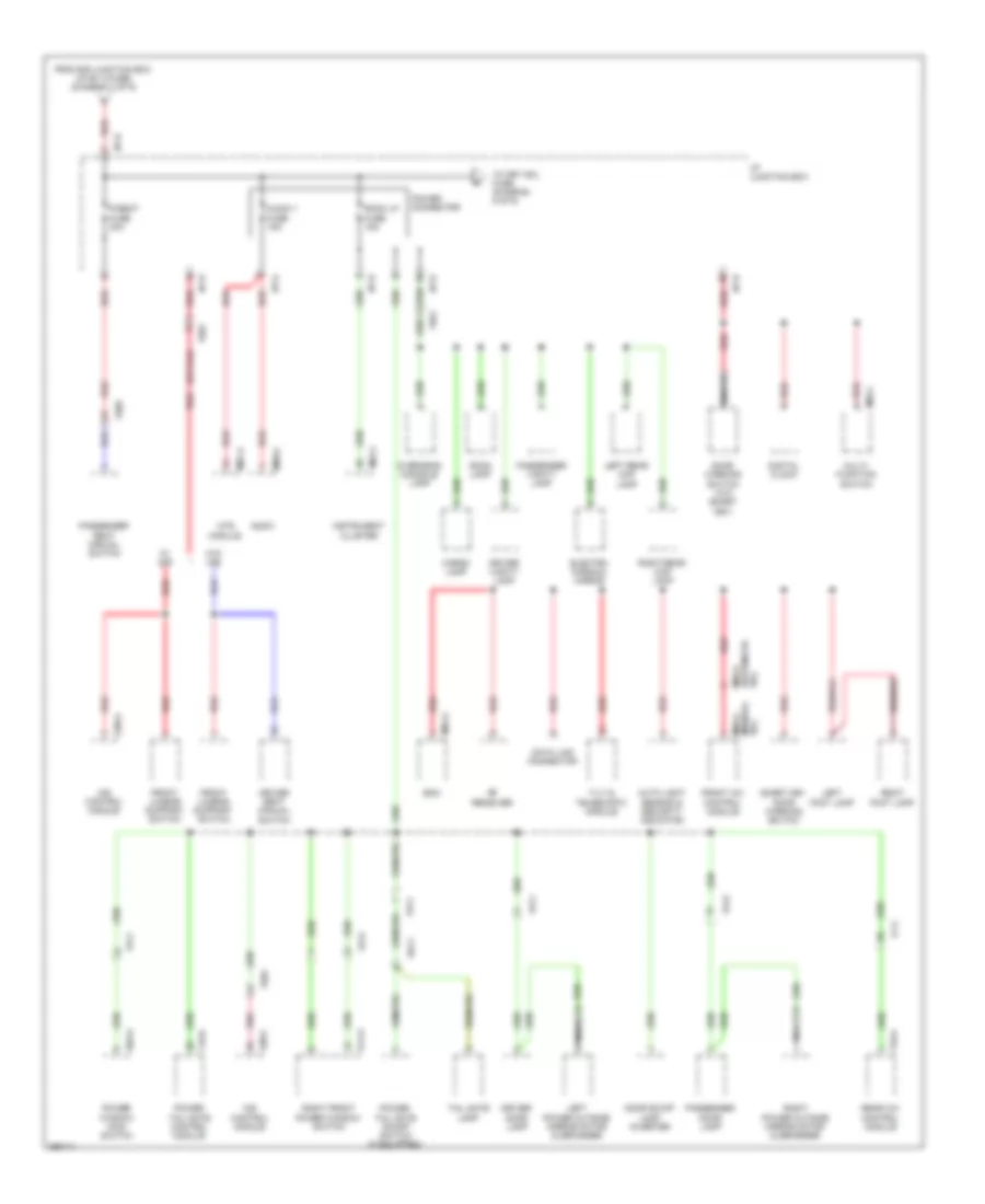 https://portal-diagnostov.com/license.html
Automotive Electricians Portal FZCO
Automotive Electricians Portal FZCO
https://portal-diagnostov.com/license.html
https://portal-diagnostov.com/license.html
Automotive Electricians Portal FZCO
Automotive Electricians Portal FZCOList of elements for Power Distribution Wiring Diagram (5 of 9) for Hyundai Veracruz Limited 2012:
- (automatic a/c)
- (manual a/c)
- Audio
- Audio 1 fuse 15a
- Auto light sensor & security indicator
- Bcm
- Cargo lamp
- D03-a
- D14-a
- Data link connector
- Digital clock
- Door scuff lamp inverter
- Door warning switch (w/o smart key)
- Driver door lamp
- Driver seat manual switch
- Driver vanity lamp
- Electro chromic mirror
- F19-b
- F70-a
- Fd11
- Fd12
- Ff11
- Fr11
- Fr61
- From e/r junction box (i/p b+ 2 fuse) (diagram 3 of 9)
- Front a/c control module
- Front lumbar support switch
- Fs01
- Fs02
- I/p junction box
- I/p-b
- I/p-e
- I/p-g
- I/p-h
- Ims control module
- Instrument cluster
- Left foot lamp
- Left power outside mirror motor & defogger
- Left rear map lamp
- M01-c
- M02-l
- M04-a
- M05-a
- M06-a
- M07-a
- M80-a
- Mts module
- Multi- function switch
- Nca
- Overhead console lamp
- P/seat fuse 30a
- Passenger door lamp
- Passenger seat manual switch
- Passenger vanity lamp
- Pnk
- Power connector
- Power tail gate control module
- Power tail gate on/off switch (if equipped)
- Power window main switch
- Rear a/c control module
- Red
- Rf receiver
- Right foot lamp
- Right front power window switch
- Right power outside mirror motor & defogger
- Right rear map lamp
- Room lamp
- Room lp fuse 15a
- Rr11
- S38-a
- S38-c
- Smart key door warning switch
- Tail gate lamp
- Tilt & telescopic module
- To key sol fuse (diagram 6 of 9)
- W/ ims
- W/o ims
Power Distribution Wiring Diagram (6 of 9) for Hyundai Veracruz Limited 2012
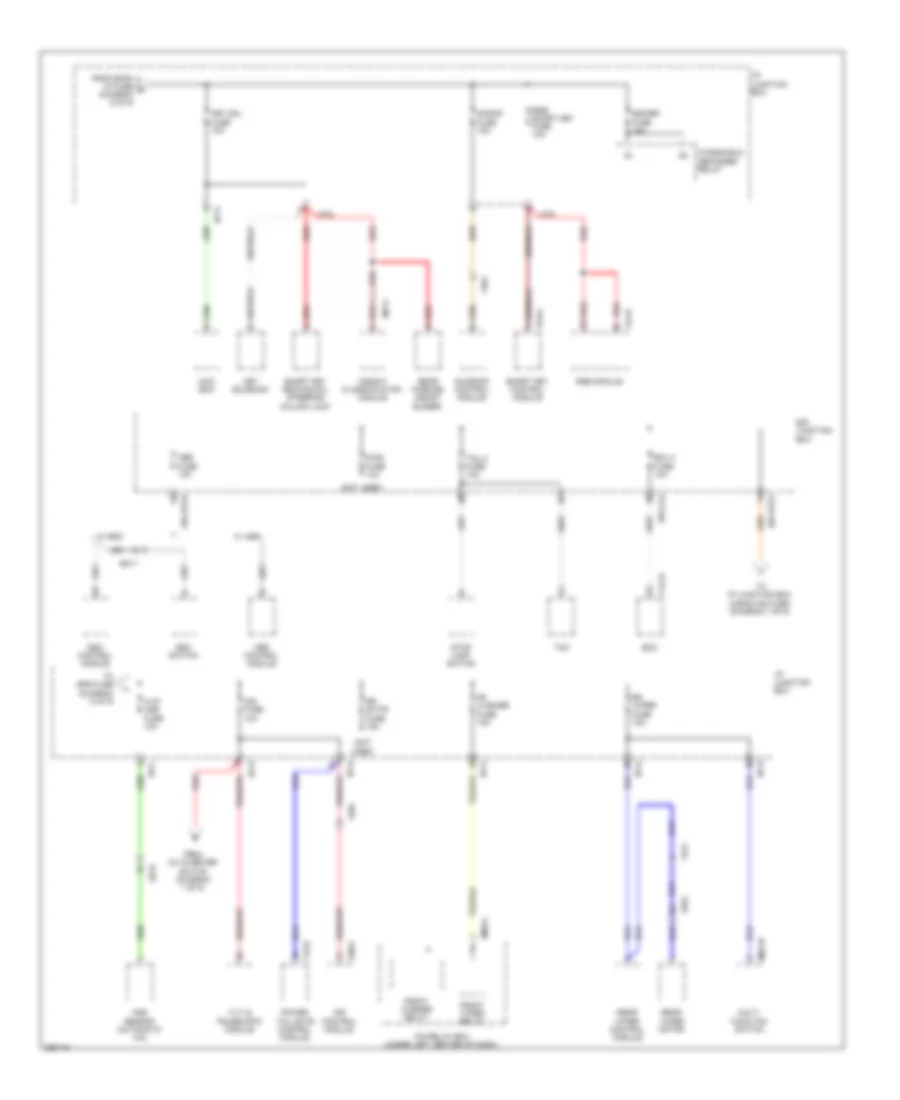 https://portal-diagnostov.com/license.html
Automotive Electricians Portal FZCO
Automotive Electricians Portal FZCO
https://portal-diagnostov.com/license.html
https://portal-diagnostov.com/license.html
Automotive Electricians Portal FZCO
Automotive Electricians Portal FZCOList of elements for Power Distribution Wiring Diagram (6 of 9) for Hyundai Veracruz Limited 2012:
- (not used)
- 4wd ecm
- Abs control module
- Abs fuse 10a
- Aqs sensor (automatic a/c)
- Clg-b
- Deicer fuse 15a
- Diag fuse 10a
- E/r junction box
- E/r-clg
- E/r-frta
- E/r-frtb
- Ecm
- Ecu 3 fuse 10a
- Ee31
- Em11
- Esc control module
- Esc switch
- F19-b
- F53-a
- F54-b
- Fr washer fuse 15a
- Fr41
- Fr61
- From ac inverter switch (diagram 1 of 9)
- From room lp fuse g (diagram 5 of 9)
- Front washer relay
- Front wiper relay
- Fs01
- H/lp aqs fuse 10a
- I/p junction box
- I/p-c
- I/p-d
- I/p-e
- I/p-f
- I/p-g
- I/p-h
- I/p-k
- Icm relay box (under left center of dash)
- Ims control module
- Ims fuse 10a
- Key sol fuse 10a
- Key solenoid
- M02-w
- M08-a
- Ma11
- Multi- function switch
- Power tail gate control module
- Rear parking assist buzzer
- Rear wiper control module
- Rear wiper motor
- Red
- Rr s/htr fuse 15a
- Rr wiper fuse 15a
- Rr21
- Rse module
- Rse/ smart key fuse 10a
- S/roof fuse 15a
- S38-c
- Smart key control module
- Smart key mechanical steering column lock
- Stop lamp switch
- Sunroof control module
- Tcm
- Tcu 2 fuse 10a
- Tilt & telescopic module
- To eps fuse (diagram 8 of 9)
- To i/p junction box (a/bag ind fuse) (diagram 7 of 9)
- W/ abs
- W/ esc
- Weight classification module
- Windshield defogger relay
Power Distribution Wiring Diagram (7 of 9) for Hyundai Veracruz Limited 2012
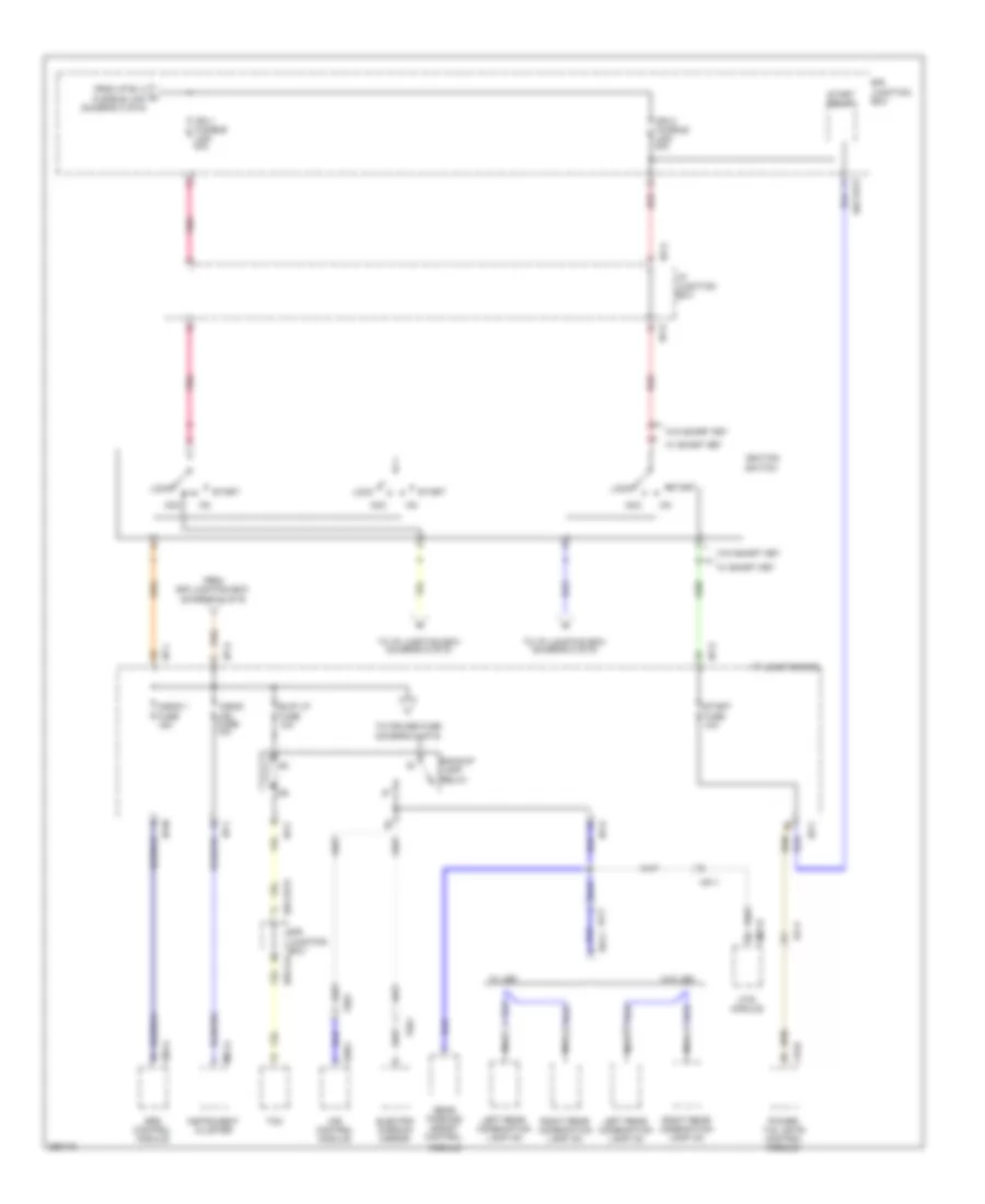 https://portal-diagnostov.com/license.html
Automotive Electricians Portal FZCO
Automotive Electricians Portal FZCO
https://portal-diagnostov.com/license.html
https://portal-diagnostov.com/license.html
Automotive Electricians Portal FZCO
Automotive Electricians Portal FZCOList of elements for Power Distribution Wiring Diagram (7 of 9) for Hyundai Veracruz Limited 2012:
- A/bag 1 fuse 15a
- A/bag ind fuse 10a
- A05-a
- Acc
- B/up lp fuse 10a
- Backup lamp relay
- E/r junction box
- E/r junction box e/r-clg
- E/r-frta
- Ef11
- Electro chromic mirror
- F19-b
- Fr11
- Fr61
- From e/r junction box (diagram 6 of 9)
- From i/p b+ 2 fusible link (diagram 3 of 9)
- Fs01
- I/p junction box
- I/p-a
- I/p-c
- I/p-d
- I/p-k
- I/p-l
- I/p-m
- Ign 1 fusible link 40a
- Ign 2 fusible link 40a
- Ignition switch
- Ims control module
- Instrument cluster
- Left rear combination lamp (in)
- Lock
- M01-a
- M07-b
- Mf11
- Module
- Mts module
- Nca
- Pnk
- Power tail gate control module
- Rear parking assist control
- Red
- Right rear combination lamp (in)
- Rr11
- S38-c
- Srs control module
- Start
- Start fuse 10a
- Start relay
- Tcm
- To cruise fuse (diagram 8 of 9)
- To i/p junction box (diagram 8 of 9)
- To i/p junction box (diagram 9 of 9)
- W/ led
- W/ smart key
- W/o led
- W/o smart key
Power Distribution Wiring Diagram (8 of 9) for Hyundai Veracruz Limited 2012
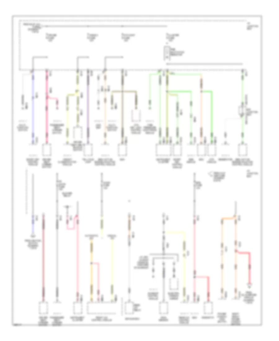 https://portal-diagnostov.com/license.html
Automotive Electricians Portal FZCO
Automotive Electricians Portal FZCO
https://portal-diagnostov.com/license.html
https://portal-diagnostov.com/license.html
Automotive Electricians Portal FZCO
Automotive Electricians Portal FZCOList of elements for Power Distribution Wiring Diagram (8 of 9) for Hyundai Veracruz Limited 2012:
- 4wd ecm
- A/bag 2 fuse 10a
- A/con fuse 10a
- Atm cont fuse 10a
- Atm key lock control module
- Automatic a/c
- Bcm
- Blower relay
- Cluster fuse 10a
- Cruise fuse 10a
- D03-a
- D14-a
- Driver seat belt buckle switch
- Driver seat warmer switch
- E/r junction box e/r-clg
- E/r sub box
- E/r-frta
- Electro- chromic mirror
- Eps fuse 10a
- F53-a
- F54-b
- F70-a
- Fd11
- Fd12
- Ff21
- Fr s/htr fuse 15a
- Fr61
- From ac inverter module (diagram 1 of 9)
- From b/up lp fuse j (diagram 7 of 9)
- From h/lp aqs fuse (diagram 6 of 9)
- From ignition switch (diagram 7 of 9)
- Front a/c control module
- Generator
- I/p junction box
- I/p-c
- I/p-d
- I/p-e
- I/p-f
- I/p-g
- I/p-h
- I/p-k
- I/p-l
- I/p-m
- Instrument cluster
- J/c jr01 (in roof console, forward of sunroof)
- M01-a
- M01-c
- M02-l
- M02-r
- M04-a
- M04-c
- M04-d
- M05-a
- M06-a
- M07-b
- Ma11
- Manual a/c
- Mc11
- Mc41
- Mf11
- Mf51
- Mf61
- Mf81
- Mts module
- Multi- function switch
- Passenger seat warmer switch
- Pnk
- Power window main switch
- Pre excitation resistor
- Rain sensor
- Rear a/c control module
- Rear a/c relay
- Red
- Rheostat
- Right front power window switch
- Rse module
- Semi active engine mounting control module
- Smart key control module
- Sunroof control module
- Telltale lamp
- Tire pressure monitoring module
- Weight classification module
Power Distribution Wiring Diagram (9 of 9) for Hyundai Veracruz Limited 2012
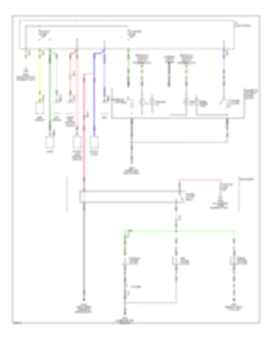 https://portal-diagnostov.com/license.html
Automotive Electricians Portal FZCO
Automotive Electricians Portal FZCO
https://portal-diagnostov.com/license.html
https://portal-diagnostov.com/license.html
Automotive Electricians Portal FZCO
Automotive Electricians Portal FZCOList of elements for Power Distribution Wiring Diagram (9 of 9) for Hyundai Veracruz Limited 2012:
- (diagram 1 of 9)
- Ac inverter
- Ashtray ill
- Atm key lock control module
- Audio
- Audio 2 fuse 10a
- Bcm
- C/lighter fuse 20a
- Cf11
- Cigarette lighter
- Cigarette lighter & power outlet
- Console power outlet
- Digital clock
- E/r sub box
- F53-a
- F54-b
- Ff11
- From
- From ignition switch (diagram 7 of 9)
- From multi- function switch (diagram 4 of 9)
- Fuse
- Gf02 (under center console)
- Gf07 (base of right "c" pillar)
- Glg01 (right rear corner of engine compt)
- Gm04 (under left side of dash)
- Hand phone tray
- I/p junction box
- I/p-d
- I/p-k
- Ill
- Interior lights system
- M04-c
- M07-a
- M80-a
- Mc31
- Mf11
- Mts module
- Nca
- P/outlet fuse 30a
- Pnk
- Power outlet
- Power outlet relay
- Rear power outlet
- Red
- Rse module
- Rse power outlet
- Smart key control module
- Tgs ill
- W/o rse
POWER DOOR LOCKS
Power Door Locks Wiring Diagram for Hyundai Veracruz Limited 2012
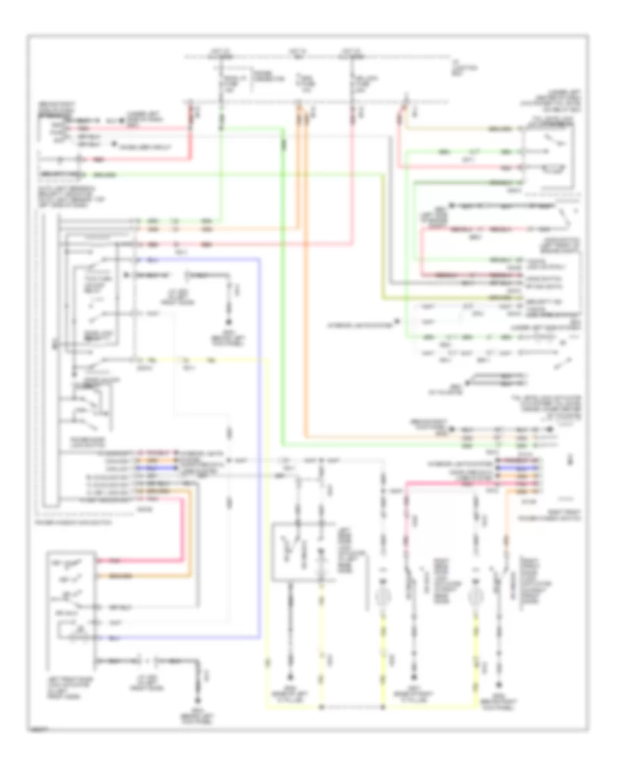 https://portal-diagnostov.com/license.html
Automotive Electricians Portal FZCO
Automotive Electricians Portal FZCO
https://portal-diagnostov.com/license.html
https://portal-diagnostov.com/license.html
Automotive Electricians Portal FZCO
Automotive Electricians Portal FZCOList of elements for Power Door Locks Wiring Diagram for Hyundai Veracruz Limited 2012:
- (behind right kick panel) gf06
- (behind right side of dash) rf receiver
- (under left center of dash) (w/o power tail gate) icm relay box
- (under left side of dash)
- Auto light sensor & security indicator (auto light sensor: top left side of dash)
- Bcm (under left side of dash)
- Can-high
- Can-low
- Computer data lines system
- D14-a
- D14-b
- Do3-a
- Do3-b
- Door lock relay
- Door unlock relay
- Dr lk
- Dr lock
- Dr lock fuse 20a
- Dr unlk
- Dr unlock
- Ee31
- Em11
- Eps fuse 10a
- Fd11
- Fd12
- Fd21
- Fd22
- Fl d/unlock sw
- Fl door sw
- Fl key lock sw
- Fl key unlock sw
- Fr11
- Fr21
- Ge01 (left side of engine compt)
- Gf03 (behind left kick panel)
- Gf06 (behind right kick panel)
- Gf07 (base of right "c" pillar)
- Gf08 (base of left "c" pillar)
- Gm01
- Gnd
- Gr01 (in tailgate)
- Hood switch
- Hood switch (left front of engine compt)
- Hot at all times
- Hot in on
- I/p junction box
- I/p-d
- I/p-e
- I/p-h
- I/p-j
- Immobilizer circuit
- Interior lights system
- Interior lights system computer data lines system
- J/c jd01 (in left front door)
- Key lk
- Key unlk
- Left front door lock actuator (in left front door)
- Left rear door lock actuator (in left rear door)
- M04-c
- M04-d
- M08-a
- Mcu
- Mf11
- Mf41
- Nca
- Pnk
- Power connector
- Power door lock switch
- Power window main switch
- Pwr
- Red
- Rf com (data)
- Right front door lock actuator (in right front door)
- Right front power window switch
- Right rear door lock actuator (in right rear door)
- Rl d/unlock sw
- Room lp fuse 15a
- Rr11
- Security ind
- Sig
- T/gate lock actr rly m04-b
- T/gate lock open status
- Tail gate lock actuator (w/o power tail gate) (inside lower center of tailgate)
- Tail gate lock actuator relay
- Two turn unlock relay
POWER MIRRORS
Electrochromic Mirror Wiring Diagram for Hyundai Veracruz Limited 2012
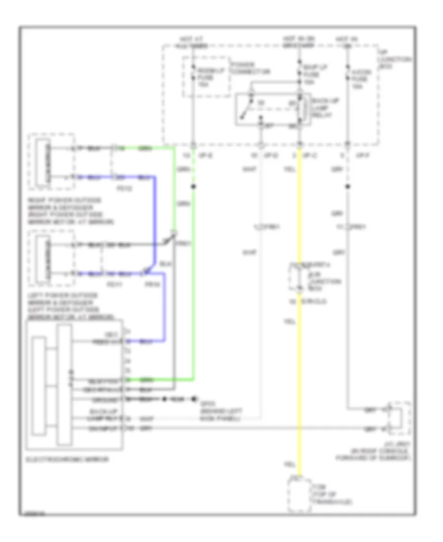 https://portal-diagnostov.com/license.html
Automotive Electricians Portal FZCO
Automotive Electricians Portal FZCO
https://portal-diagnostov.com/license.html
https://portal-diagnostov.com/license.html
Automotive Electricians Portal FZCO
Automotive Electricians Portal FZCOList of elements for Electrochromic Mirror Wiring Diagram for Hyundai Veracruz Limited 2012:
- A/con fuse 10a
- B/up lp fuse 10a
- Back-up lamp relay
- Back-up lamp rly
- E/r junction box
- E/r-clg
- E/r-frta
- Ecm mirror
- Electrochromic mirror
- Fd11
- Fd12
- Fr16
- Fr61
- Gf03 (behind left kick panel)
- Ground
- Hot at all times
- Hot in on
- Hot in on or start
- I/p junction box
- I/p-c
- I/p-d
- I/p-e
- I/p-f
- J/c jr01 (in roof console, forward of sunroof)
- Left power outside mirror & defogger (left power outside mirror motor: at mirror)
- Mem pwr
- Oec feed (+)
- Oec rtn (-)
- On input
- P c b
- Power connector
- Right power outside mirror & defogger (right power outside mirror motor: at mirror)
- Room lp fuse 15a
- Tcm (top of transaxle)
Power Mirrors Wiring Diagram for Hyundai Veracruz Limited 2012
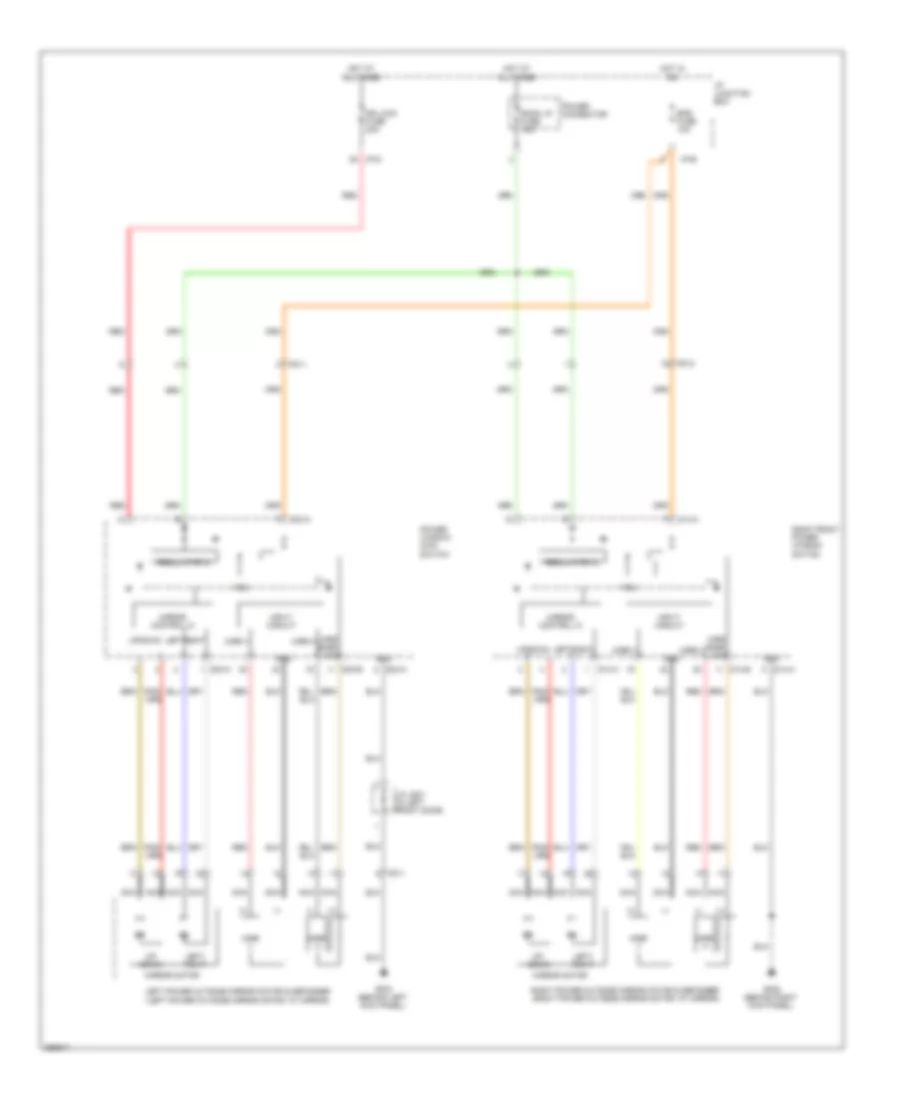 https://portal-diagnostov.com/license.html
Automotive Electricians Portal FZCO
Automotive Electricians Portal FZCO
https://portal-diagnostov.com/license.html
https://portal-diagnostov.com/license.html
Automotive Electricians Portal FZCO
Automotive Electricians Portal FZCOList of elements for Power Mirrors Wiring Diagram for Hyundai Veracruz Limited 2012:
- (+)
- (-)
- D03-a
- D03-b
- D14-a
- D14-b
- Down
- Dr lock fuse 20a
- Eps fuse 10a
- Fd11
- Fd12
- Gf03 (behind left kick panel)
- Gf06 (behind right kick panel)
- Gnd
- Hot at all times
- Hot in on
- I/p junction box
- I/p-d
- I/p-e
- Input circuit
- J/c jd01 (in left front door)
- Left
- Left power outside mirror motor & defogger (left power outside mirror motor: at mirror)
- Left/ right
- Mcu
- Mirr h
- Mirr snsr vcc
- Mirr v
- Mirror control ic
- Mirror motor
- Nca
- Power connector
- Power window main switch
- Red
- Regulator ic
- Right
- Right front power window switch
- Right power outside mirror motor & defogger (right power outside mirror motor: at mirror)
- Room lp fuse 15a
- Up/ down
POWER SEATS
Adjustable Pedal Wiring Diagram for Hyundai Veracruz Limited 2012
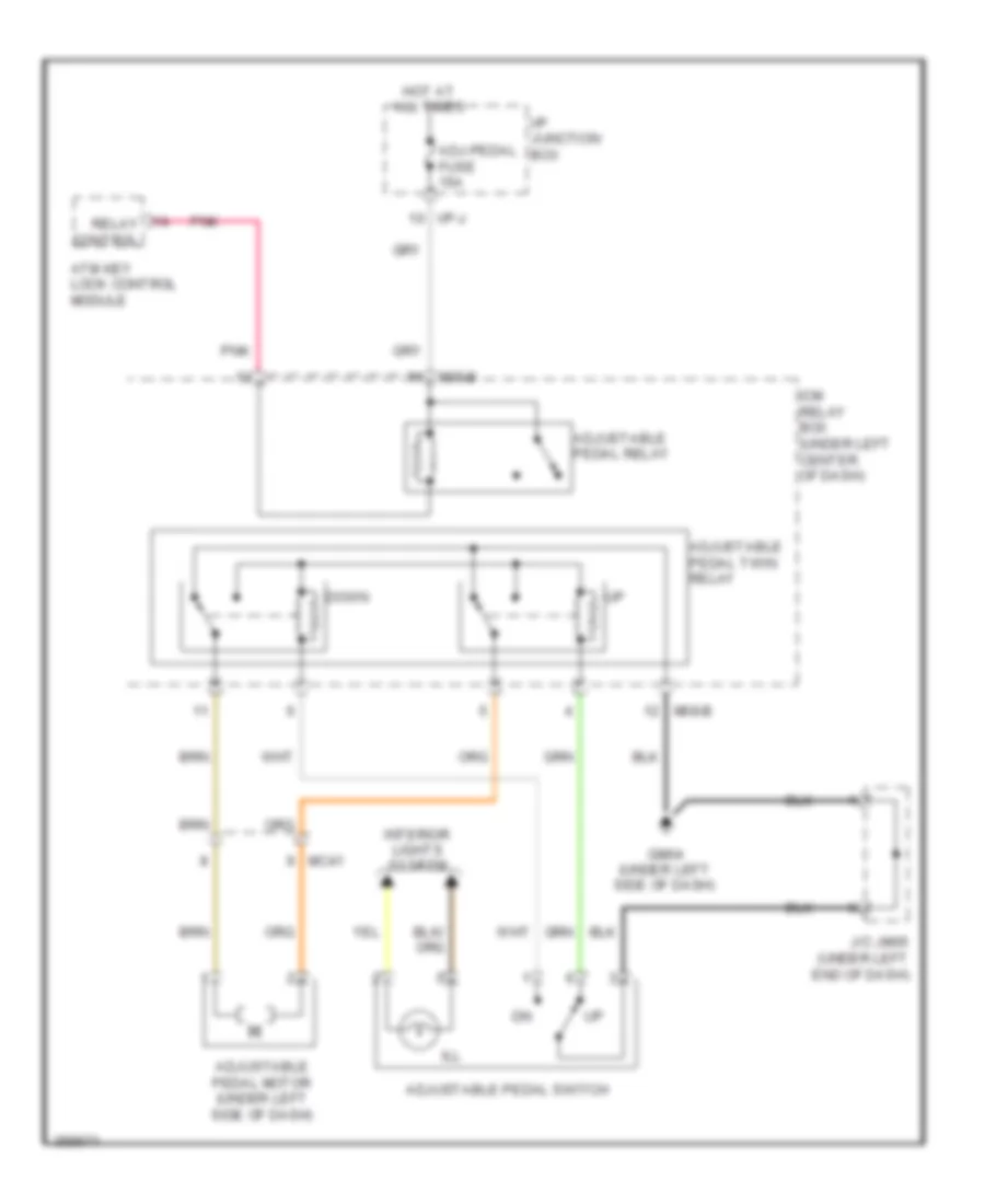 https://portal-diagnostov.com/license.html
Automotive Electricians Portal FZCO
Automotive Electricians Portal FZCO
https://portal-diagnostov.com/license.html
https://portal-diagnostov.com/license.html
Automotive Electricians Portal FZCO
Automotive Electricians Portal FZCOList of elements for Adjustable Pedal Wiring Diagram for Hyundai Veracruz Limited 2012:
- Adj-pedal fuse 15a
- Adjustable pedal motor (under left side of dash)
- Adjustable pedal relay
- Adjustable pedal switch
- Adjustable pedal twin relay
- Atm key lock control module
- Down
- Gm04 (under left side of dash)
- Hot at all times
- I/p junction box
- I/p-j
- Icm relay box (under left center of dash)
- Ill
- Interior lights system
- J/c jm05 (under left end of dash)
- M08-b
- Mc41
- Pnk
- Relay control
Driver Power Seat Wiring Diagram for Hyundai Veracruz Limited 2012
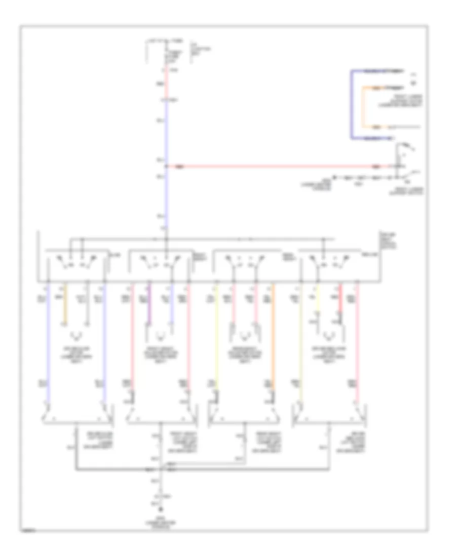 https://portal-diagnostov.com/license.html
Automotive Electricians Portal FZCO
Automotive Electricians Portal FZCO
https://portal-diagnostov.com/license.html
https://portal-diagnostov.com/license.html
Automotive Electricians Portal FZCO
Automotive Electricians Portal FZCOList of elements for Driver Power Seat Wiring Diagram for Hyundai Veracruz Limited 2012:
- (under driver's seat)
- Driver reclining limit switch (under driver's seat)
- Driver reclining motor (under driver's seat)
- Driver seat manual switch
- Driver slide limit switch
- Driver slide motor (under driver's seat)
- Front height
- Front height adjuster motor (under driver's seat)
- Front height limit switch (under left side of driver's seat)
- Front lumbar support motor (under driver's seat)
- Front lumbar support switch
- Fs01
- Gf05 (under center console)
- Hot at all times
- I/p junction box
- I/p-e
- Nca
- P/seat fuse 30a
- Rear height
- Rear height adjuster motor (under driver's seat)
- Rear height limit switch (under left side of driver's seat)
- Recline
- Red
- Slide
Heated Seats Wiring Diagram for Hyundai Veracruz Limited 2012
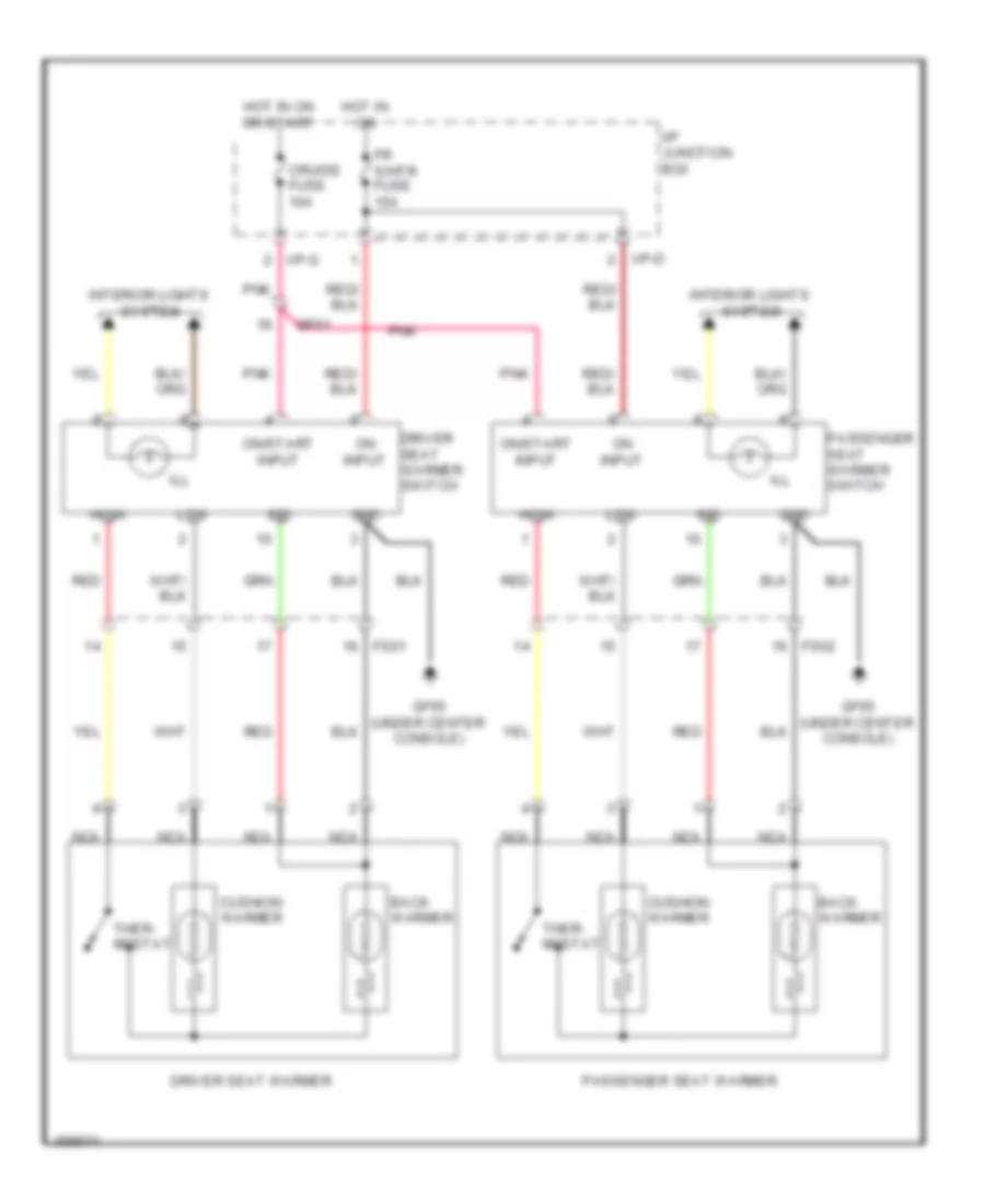 https://portal-diagnostov.com/license.html
Automotive Electricians Portal FZCO
Automotive Electricians Portal FZCO
https://portal-diagnostov.com/license.html
https://portal-diagnostov.com/license.html
Automotive Electricians Portal FZCO
Automotive Electricians Portal FZCOList of elements for Heated Seats Wiring Diagram for Hyundai Veracruz Limited 2012:
- Back warmer
- Cruise fuse 10a
- Cushion warmer
- Driver seat warmer
- Driver seat warmer switch
- Fr s/htr fuse 15a
- Fs01
- Fs02
- Gf05 (under center console)
- Gnd
- High
- Hot in on
- Hot in on or start
- I/p junction box
- I/p-d
- I/p-g
- Ill
- Ind
- Interior lights system
- Low
- Mf61
- Nca
- On input
- On/start input
- Passenger seat warmer
- Passenger seat warmer switch
- Pnk
- Red
- Ther- mostat
Passenger Power Seat Wiring Diagram for Hyundai Veracruz Limited 2012
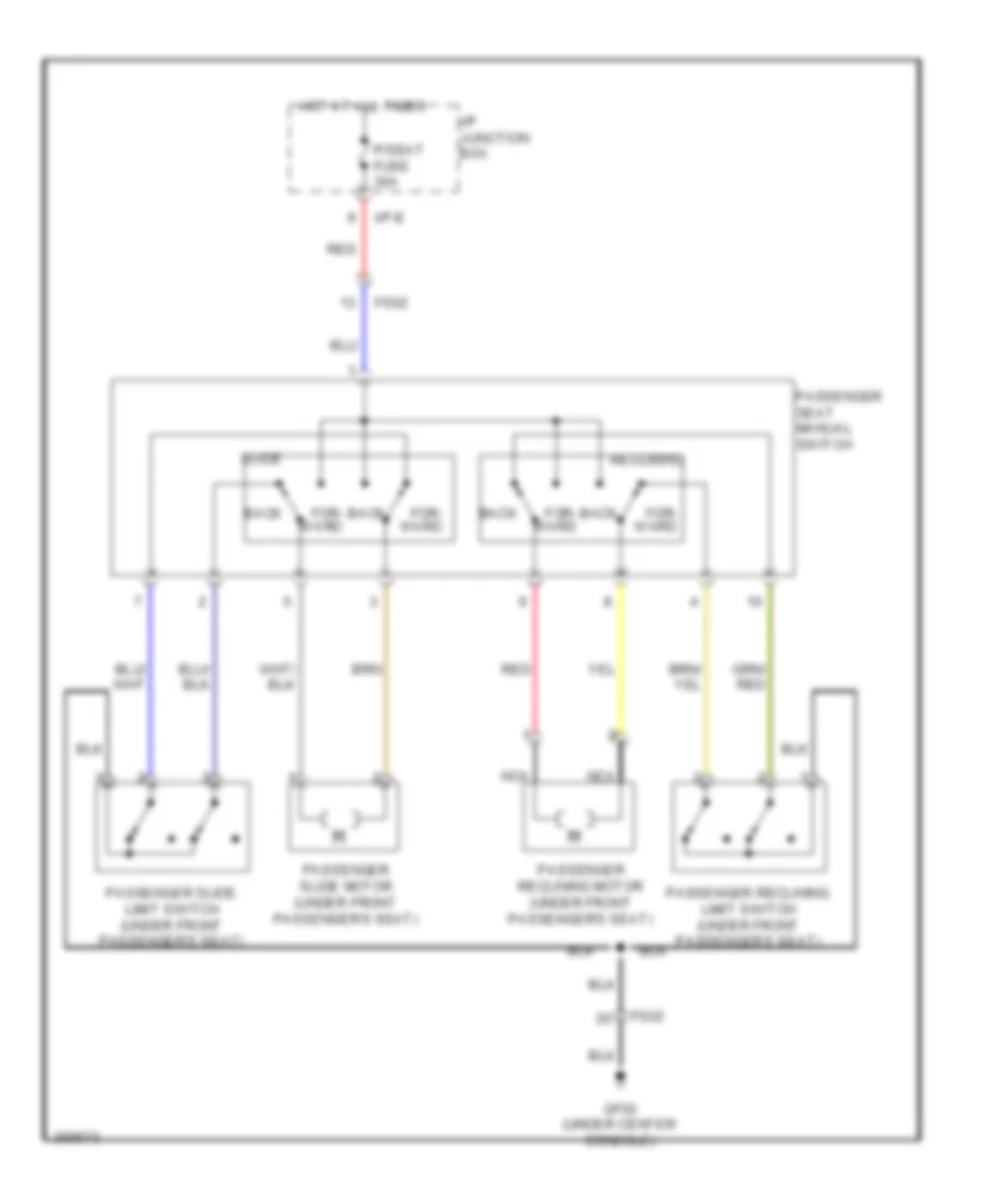 https://portal-diagnostov.com/license.html
Automotive Electricians Portal FZCO
Automotive Electricians Portal FZCO
https://portal-diagnostov.com/license.html
https://portal-diagnostov.com/license.html
Automotive Electricians Portal FZCO
Automotive Electricians Portal FZCOList of elements for Passenger Power Seat Wiring Diagram for Hyundai Veracruz Limited 2012:
- Back
- For- ward
- Fs02
- Gf02 (under center console)
- Hot at all times
- I/p junction box
- I/p-e
- Nca
- P/seat fuse 30a
- Passenger reclining limit switch (under front passenger's seat)
- Passenger reclining motor (under front passenger's seat)
- Passenger seat manual switch
- Passenger slide limit switch (under front passenger's seat)
- Passenger slide motor (under front passenger's seat)
- Reclining
- Red
- Slide
POWER TOP/SUNROOF
Power Top/Sunroof Wiring Diagram for Hyundai Veracruz Limited 2012
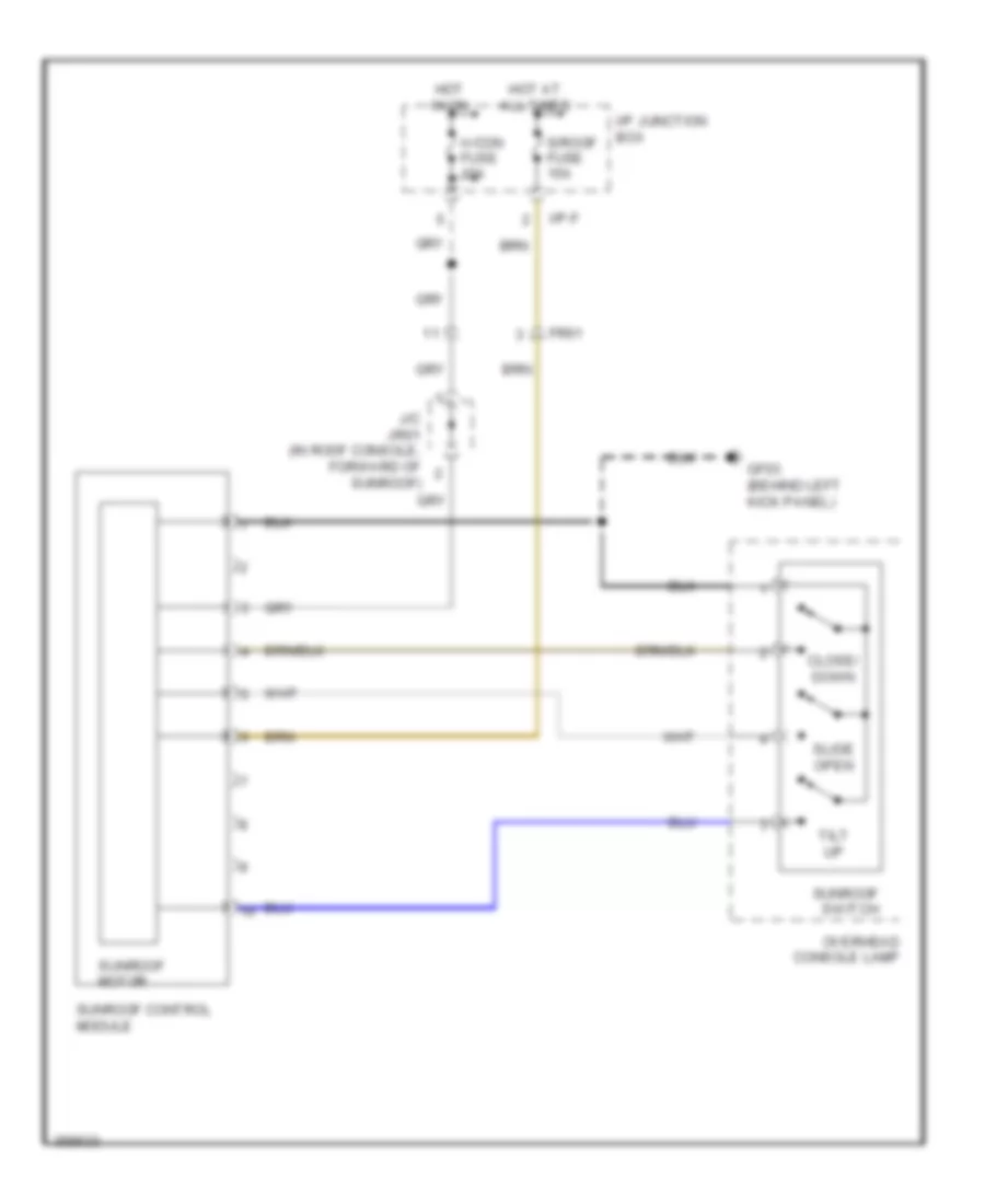 https://portal-diagnostov.com/license.html
Automotive Electricians Portal FZCO
Automotive Electricians Portal FZCO
https://portal-diagnostov.com/license.html
https://portal-diagnostov.com/license.html
Automotive Electricians Portal FZCO
Automotive Electricians Portal FZCOList of elements for Power Top/Sunroof Wiring Diagram for Hyundai Veracruz Limited 2012:
- A/con fuse 10a
- Close/ down
- Fr61
- Gf03 (behind left kick panel)
- Hot at all times
- Hot in on
- I/p junction box
- I/p-f
- J/c jr01 (in roof console, forward of sunroof)
- Overhead console lamp
- S/roof fuse 15a
- Slide open
- Sunroof control module
- Sunroof motor
- Sunroof switch
- Tilt up
POWER WINDOWS
Power Windows Wiring Diagram (1 of 2) for Hyundai Veracruz Limited 2012
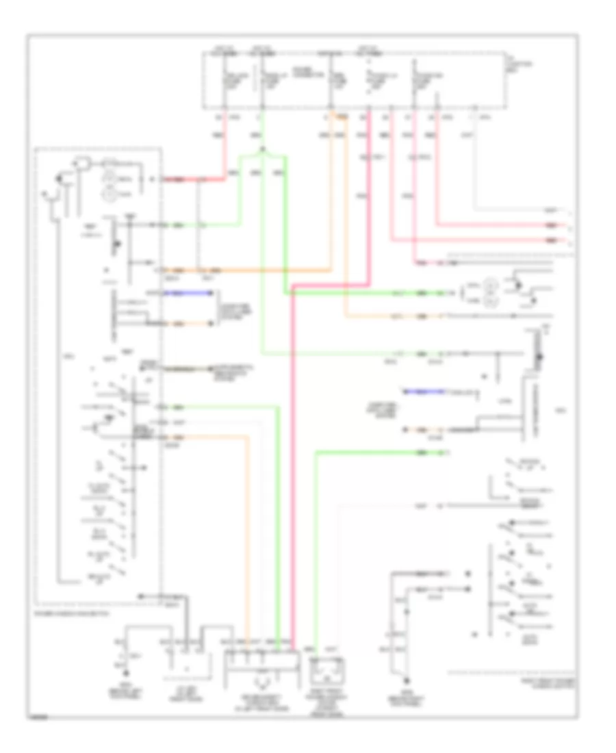 https://portal-diagnostov.com/license.html
Automotive Electricians Portal FZCO
Automotive Electricians Portal FZCO
https://portal-diagnostov.com/license.html
https://portal-diagnostov.com/license.html
Automotive Electricians Portal FZCO
Automotive Electricians Portal FZCOList of elements for Power Windows Wiring Diagram (1 of 2) for Hyundai Veracruz Limited 2012:
- +5v
- 12v
- Auto down
- Auto up
- Can transceiver ic
- Can-high
- Can-low
- Computer data lines system
- Cpu
- Crash output
- D03-a
- D03-b
- D14-a
- D14-b
- Down
- Dr lock fuse 20a
- Driver safety window ecm (in left front door)
- Eps fuse 10a
- Fd11
- Fd12
- Fl auto down
- Fl up
- Fr pwd down
- Fr pwd up
- Gf03 (behind left kick panel)
- Gf06 (behind right kick panel)
- High
- Hot at all times
- Hot in on
- I/p junction box
- I/p-a
- I/p-d
- I/p-e
- J/c jd01 (in left front door)
- Low
- M/ down
- M/ up
- Mcu
- P/wdw lh fuse 25a
- P/wdw rh fuse 25a
- Pnk
- Power connector
- Power window main switch
- Pwd enable (lock)
- Red
- Regulator ic
- Right front power window motor (in right front door)
- Right front power window switch
- Rl auto up
- Rl m down
- Rl m up
- Room lp fuse 15a
- Rr auto up
Power Windows Wiring Diagram (2 of 2) for Hyundai Veracruz Limited 2012
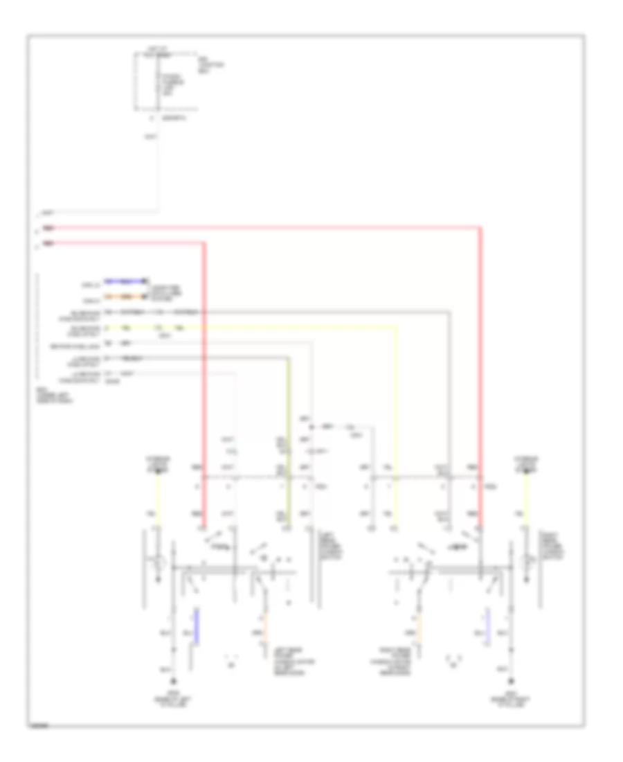 https://portal-diagnostov.com/license.html
Automotive Electricians Portal FZCO
Automotive Electricians Portal FZCO
https://portal-diagnostov.com/license.html
https://portal-diagnostov.com/license.html
Automotive Electricians Portal FZCO
Automotive Electricians Portal FZCOList of elements for Power Windows Wiring Diagram (2 of 2) for Hyundai Veracruz Limited 2012:
- Bcm (under left side of dash)
- Can hi
- Can lo
- Computer data lines system
- Down
- E/r junction box
- E/r-frta
- Fd21
- Fd22
- Gf07 (base of right "c" pillar)
- Gf08 (base of left "c" pillar)
- Hot at all times
- Ill
- Interior lights system
- Left rear power window motor (in left rear door)
- Left rear power window switch
- Lh rr pwr wind down rly m04-b
- Lh rr pwr wind up rly
- Mf11
- Mf31
- P/wdw fusible link 40a
- Red
- Rh rr pwr wind down rly
- Rh rr pwr wind up rly
- Right rear power window motor (in right rear door)
- Right rear power window switch
- Rr pwr wind lock
RADIO
Radio Wiring Diagram, with Amplifier (1 of 2) for Hyundai Veracruz Limited 2012
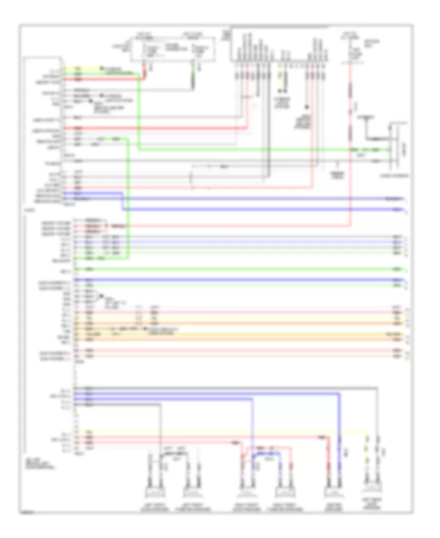 https://portal-diagnostov.com/license.html
Automotive Electricians Portal FZCO
Automotive Electricians Portal FZCO
https://portal-diagnostov.com/license.html
https://portal-diagnostov.com/license.html
Automotive Electricians Portal FZCO
Automotive Electricians Portal FZCOList of elements for Radio Wiring Diagram, with Amplifier (1 of 2) for Hyundai Veracruz Limited 2012:
- Acc/on in
- Amp fuse 30a
- Antenna
- Audio
- Audio 1 fuse 15a
- Audio 2 fuse 10a
- Aux detect
- Aux l
- Aux r
- Aux ref
- Aux shield
- Aux usb jack
- Center speaker
- Cf11
- Circuit
- Computer data lines system
- E/r sub box
- Eq sel
- F/cable
- F06-a
- F06-b
- Fd11
- Fd12
- Fd21
- Feeder cable
- Ff51
- Fl (+)
- Fl (-)
- Fr (+)
- Fr (-)
- Frt ctr (+)
- Frt ctr (-)
- Gf04 (at left "c" pillar)
- Gm03 (behind center of dash)
- Gnd
- Hot at all times
- Hot in acc or on
- I/p junction box
- I/p-g
- I/p-k
- Ill (+)
- Ill (-)
- Interior lights system
- Jbl amp (behind left quarterpanel)
- Left front door speaker
- Left front tweeter speaker
- Left rear door speaker
- M80-a
- M80-c2
- M80-c3
- Memory power
- Memory pwr
- Mf11
- Mf21
- Mf41
- Mf51
- Micro antenna
- Nca
- Power connector
- Re on/off
- Red
- Remocon gnd
- Remocon sig
- Remote amp
- Right front door speaker
- Right front tweeter speaker
- Rl (+)
- Rl (-)
- Rr (+)
- Rr (-)
- Sub woofer l (+)
- Sub woofer l (-)
- Sub woofer r (+)
- Sub woofer r (-)
- Usb 5v
- Usb d+/ipod rx
- Usb d-/ipod tx
- Usb gnd
- Usb shield
- Vss
Radio Wiring Diagram, with Amplifier (2 of 2) for Hyundai Veracruz Limited 2012
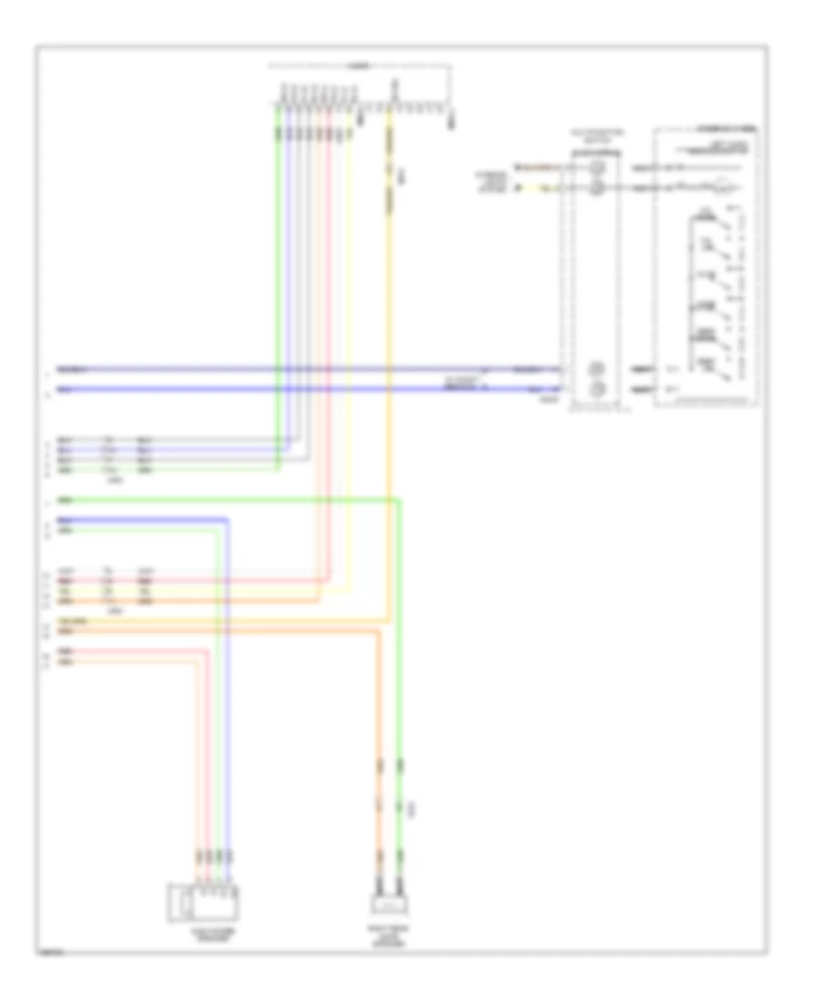 https://portal-diagnostov.com/license.html
Automotive Electricians Portal FZCO
Automotive Electricians Portal FZCO
https://portal-diagnostov.com/license.html
https://portal-diagnostov.com/license.html
Automotive Electricians Portal FZCO
Automotive Electricians Portal FZCOList of elements for Radio Wiring Diagram, with Amplifier (2 of 2) for Hyundai Veracruz Limited 2012:
- (+)
- (-)
- Audio
- Clock spring
- Eq sel
- Fd22
- Fl (+)
- Fl (-)
- Fr (+)
- Fr (-)
- Ill
- Interior lights system
- Left audio remocon switch
- M02-r
- M80-b
- M80-c1
- Mf51
- Mf91
- Mode
- Multifunction switch
- Mute
- Nca
- Red
- Right rear door speaker
- Rl (+)
- Rl (-)
- Rr (+)
- Rr (-)
- Seek down
- Seek up
- Steering wheel
- Sub woofer speaker
- Vol down
- Vol up
- W/ audio remocon
Radio Wiring Diagram, with Navigation (1 of 2) for Hyundai Veracruz Limited 2012
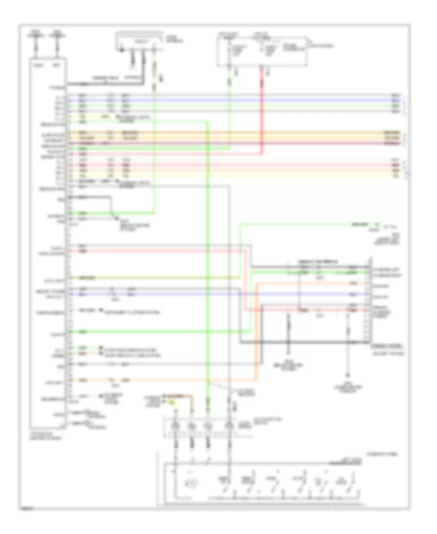 https://portal-diagnostov.com/license.html
Automotive Electricians Portal FZCO
Automotive Electricians Portal FZCO
https://portal-diagnostov.com/license.html
https://portal-diagnostov.com/license.html
Automotive Electricians Portal FZCO
Automotive Electricians Portal FZCOList of elements for Radio Wiring Diagram, with Navigation (1 of 2) for Hyundai Veracruz Limited 2012:
- (+)
- (-)
- (behind center
- (center of dash)
- Acc/on in
- Alt l
- Antenna
- Audio 1 fuse 15a
- Audio 2 fuse 10a
- Audio common
- Audio l
- Audio r
- Auto light
- Av tail
- Bcm (under left side of dash)
- Can high
- Can high 1
- Can low
- Can low 1
- Cdma
- Cdma antenna
- Circuit
- Clock spring
- Computer data lines system
- Eq select
- Exterior lights system
- F/cable
- Feeder cable
- Fl (+)
- Fl (-)
- Fr (+)
- Fr (-)
- Gf01 (under center console)
- Gm03
- Gm03 (behind center of dash)
- Gnd
- Gps
- Gps antenna
- Ground
- Hot at all times
- Hot in acc or on
- I/p junction box
- I/p-g
- I/p-k
- Ill
- Ill (+)
- Ill (-)
- Instrument cluster system
- Interior lights system
- Left audio remocon switch
- M02-r
- M04-b
- M07-a
- M07-b
- Memory power
- Memory pwr
- Mf31
- Mf51
- Mf91
- Micro antenna
- Mode
- Mts module
- Multifunction switch
- Mute
- Nca
- Of dash)
- Parking break
- Power connector
- Radio
- Radio antenna
- Red
- Remocon gnd
- Remocon sig
- Remote amp
- Reverse sig
- Rl (+)
- Rl (-)
- Rr (+)
- Rr (-)
- Seek down
- Seek up
- Speed
- Starting/charging system
- Steering wheel
- Surr on/off
- Tv antenna
- Usa set top box
- Vol down
- Vol up
- W/ audio remocon
- Xm sdars common
- Xm sdars left
- Xm sdars right
Radio Wiring Diagram, with Navigation (2 of 2) for Hyundai Veracruz Limited 2012
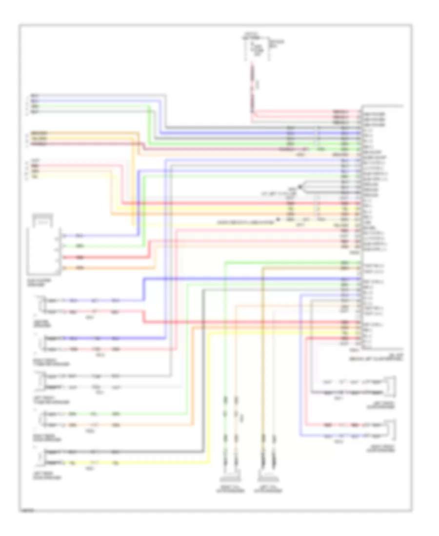 https://portal-diagnostov.com/license.html
Automotive Electricians Portal FZCO
Automotive Electricians Portal FZCO
https://portal-diagnostov.com/license.html
https://portal-diagnostov.com/license.html
Automotive Electricians Portal FZCO
Automotive Electricians Portal FZCOList of elements for Radio Wiring Diagram, with Navigation (2 of 2) for Hyundai Veracruz Limited 2012:
- (+)
- (-)
- Amp fuse 30a
- Center speaker
- Cf11
- Computer data lines system
- E/r sub box
- Eq sel
- F06-a
- F06-b
- Fd11
- Fd12
- Fd21
- Fd22
- Ff51
- Fl (+)
- Fl (-)
- Fr (+)
- Fr (-)
- Fr41
- Frt ctr (+)
- Frt ctr (-)
- Gf04 (at left "c" pillar)
- Ground
- Hot at all times
- Jbl amp (behind left quarterpanel)
- Left front door speaker
- Left front tweeter speaker
- Left rear door speaker
- Left tail gate speaker
- Lh twtr (+)
- Lh twtr (-)
- Mem power
- Mf11
- Mf21
- Mf41
- Nca
- Re on/off
- Red
- Rh twtr (+)
- Rh twtr (-)
- Right front door speaker
- Right front tweeter speaker
- Right rear door speaker
- Right tail gate speaker
- Rl (+)
- Rl (-)
- Rr (+)
- Rr (-)
- Sub wfr l (+)
- Sub wfr l (-)
- Sub wfr r (+)
- Sub wfr r (-)
- Sub woofer speaker
- Surr on/off
- Tgat lh (+)
- Tgat lh (-)
- Tgat rh (+)
- Tgat rh (-)
- Vss
Radio Wiring Diagram, without Amplifier for Hyundai Veracruz Limited 2012
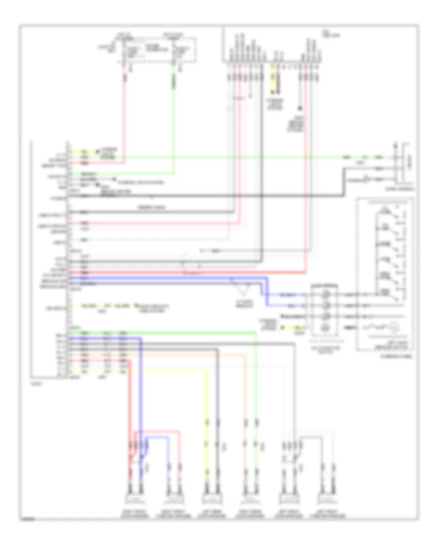 https://portal-diagnostov.com/license.html
Automotive Electricians Portal FZCO
Automotive Electricians Portal FZCO
https://portal-diagnostov.com/license.html
https://portal-diagnostov.com/license.html
Automotive Electricians Portal FZCO
Automotive Electricians Portal FZCOList of elements for Radio Wiring Diagram, without Amplifier for Hyundai Veracruz Limited 2012:
- (+)
- (-)
- Acc/on in
- Antenna
- Audio
- Audio 1 fuse 15a
- Audio 2 fuse 10a
- Aux detect
- Aux l
- Aux r
- Aux ref
- Aux shield
- Aux usb jack
- Circuit
- Clock spring
- Computer data lines system
- F/cable
- Fd11
- Fd12
- Fd21
- Fd22
- Feeder cable
- Fl (+)
- Fl (-)
- Fr (+)
- Fr (-)
- Gm03 (behind center of dash)
- Gnd
- Hot at all times
- Hot in acc or on
- I/p junction box
- I/p-g
- I/p-k
- Ill
- Ill (+)
- Ill (-)
- Interior lights system
- Left audio remocon switch
- Left front door speaker
- Left front tweeter speaker
- Left rear door speaker
- M02-r
- M80-a
- M80-b
- M80-c1
- M80-c2
- M80-c3
- Memory pwr
- Mf51
- Mf91
- Micro antenna
- Mode
- Multifunction switch
- Mute
- Nca
- Power connector
- Red
- Remocon gnd
- Remocon sig
- Right front door speaker
- Right front tweeter speaker
- Right rear door speaker
- Rl (+)
- Rl (-)
- Rr (+)
- Rr (-)
- Seek down
- Seek up
- Steering wheel
- Usb 5v
- Usb d+/ipod rx
- Usb d-/ipod tx
- Usb gnd
- Usb shield
- Veh spd in
- Vol down
- Vol up
- W/ audio remocon
Rear Seat Entertainment Wiring Diagram (1 of 3) for Hyundai Veracruz Limited 2012
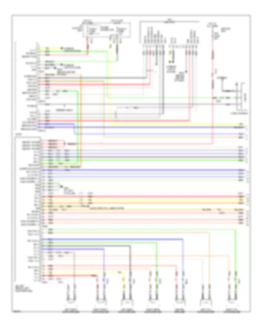 https://portal-diagnostov.com/license.html
Automotive Electricians Portal FZCO
Automotive Electricians Portal FZCO
https://portal-diagnostov.com/license.html
https://portal-diagnostov.com/license.html
Automotive Electricians Portal FZCO
Automotive Electricians Portal FZCOList of elements for Rear Seat Entertainment Wiring Diagram (1 of 3) for Hyundai Veracruz Limited 2012:
- Acc/on in
- Amp fuse 30a
- Antenna
- Audio
- Audio 1 fuse 15a
- Audio 2 fuse 10a
- Aux detect
- Aux l
- Aux r
- Aux ref
- Aux shield
- Aux usb jack
- Can high
- Can low
- Center speaker
- Cf11
- Circuit
- Computer data lines system
- E/r sub box
- Eq sel
- F/cable
- F06-a
- F06-b
- Fd11
- Fd12
- Fd21
- Fd22
- Feeder cable
- Ff51
- Fl (+)
- Fl (-)
- Fr (+)
- Fr (-)
- Fr41
- Frt ctr (+)
- Frt ctr (-)
- Gf04 (at left "c" pillar)
- Gm03 (behind center of dash)
- Gnd
- Hot at all times
- Hot in acc or on
- I/p junction box
- I/p-d
- I/p-g
- I/p-k
- Ill (+)
- Ill (-)
- Interior lights system
- Ipod rx
- Ipod tx
- Jbl amp (behind left quarterpanel)
- Left front door speaker
- Left rear door speaker
- Left tail gate speaker
- Lf twtr (+)
- Lh twtr (-)
- M80-a
- M80-c2
- M80-c3
- Memory power
- Memory pwr
- Mf11
- Mf21
- Mf41
- Mf51
- Micro antenna
- Nca
- Power connector
- Re on/off
- Red
- Remocon gnd
- Remocon sig
- Remote amp
- Rh twtr (+)
- Rh twtr (-)
- Right front door speaker
- Right rear door speaker
- Right tail gate speaker
- Rl (+)
- Rl (-)
- Rr (+)
- Rr (-)
- Sub woofer l (+)
- Sub woofer l (-)
- Sub woofer r (+)
- Sub woofer r (-)
- Surround
- Surround on/off
- Tgat lh (+)
- Tgat lh (-)
- Tgat rh (+)
- Tgat rh (-)
- Usb 5v
- Usb d+/ipod rx
- Usb d-/ipod tx
- Usb gnd
- Usb shield
- Vss
Rear Seat Entertainment Wiring Diagram (2 of 3) for Hyundai Veracruz Limited 2012
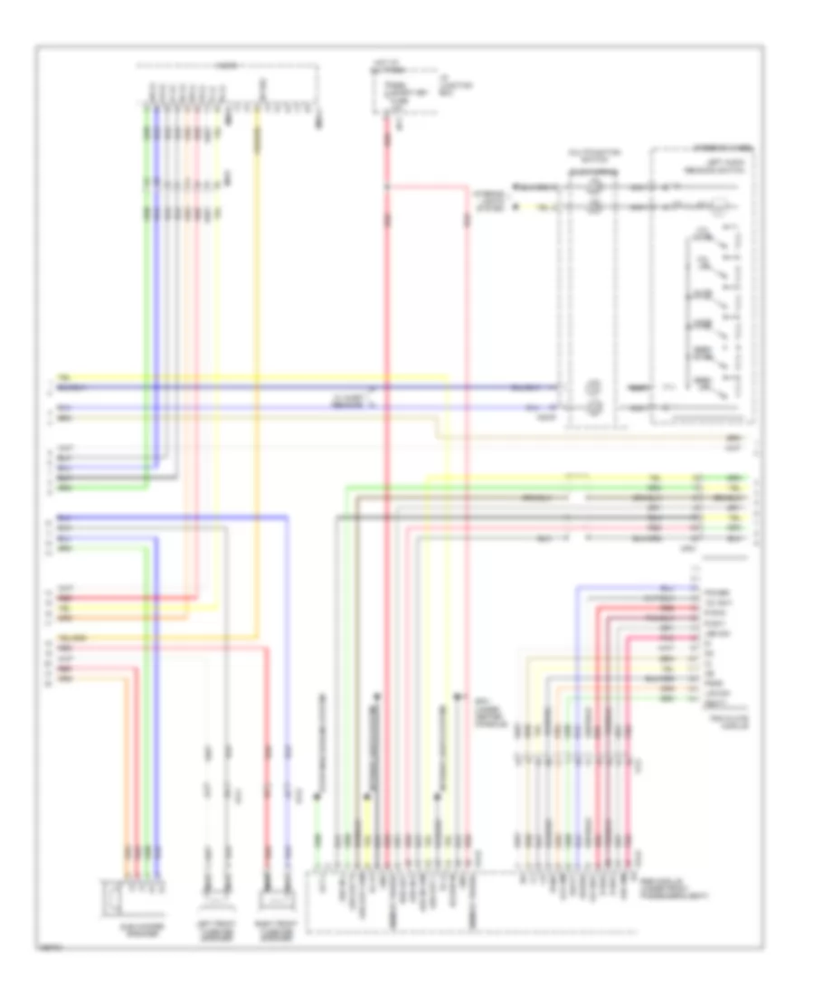 https://portal-diagnostov.com/license.html
Automotive Electricians Portal FZCO
Automotive Electricians Portal FZCO
https://portal-diagnostov.com/license.html
https://portal-diagnostov.com/license.html
Automotive Electricians Portal FZCO
Automotive Electricians Portal FZCOList of elements for Rear Seat Entertainment Wiring Diagram (2 of 3) for Hyundai Veracruz Limited 2012:
- (+)
- (-)
- (under center console)
- 12v sw1
- Acc/on in
- Alt l
- Aud in com
- Aud in l
- Aud in r
- Aud out com
- Aud out l
- Aud out r
- Audio
- Clock spring
- Eq sel
- F54-b
- F54-d
- Fbatt
- Fd11
- Fd12
- Ff21
- Fl (+)
- Fl (-)
- Fr (+)
- Fr (-)
- Gf01
- Gnd
- Hot at all times
- I/p junction box
- I/p-f
- Ill
- Ill (+)
- Ill (-)
- Interior lights system
- Lcd dim
- Led dim
- Left audio remocon switch
- Left front tweeter speaker
- M02-r
- M80-b
- M80-c1
- Memory power
- Mf81
- Mf91
- Mode
- Multifunction switch
- Mute
- Nca
- Pgnd
- Pnk
- Power
- R sw1
- R sw2
- Red
- Right front tweeter speaker
- Rl (+)
- Rl (-)
- Rr (+)
- Rr (-)
- Rse det
- Rse module (under front passenger's seat)
- Rse/ smart key fuse 10a
- Seek down
- Seek up
- Starting/charging system
- Steering wheel
- Sub woofer speaker
- Trim plate module
- Vol down
- Vol up
- W/ audio remocon
Rear Seat Entertainment Wiring Diagram (3 of 3) for Hyundai Veracruz Limited 2012
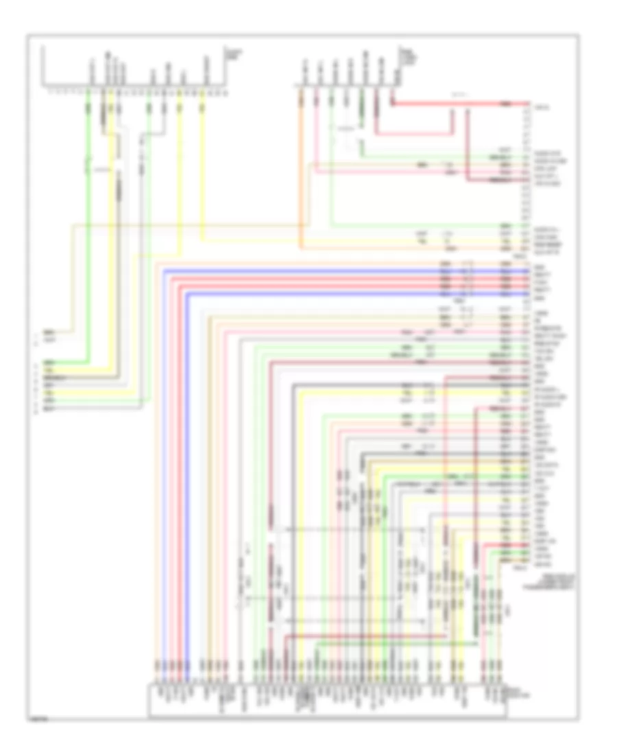 https://portal-diagnostov.com/license.html
Automotive Electricians Portal FZCO
Automotive Electricians Portal FZCO
https://portal-diagnostov.com/license.html
https://portal-diagnostov.com/license.html
Automotive Electricians Portal FZCO
Automotive Electricians Portal FZCOList of elements for Rear Seat Entertainment Wiring Diagram (3 of 3) for Hyundai Veracruz Limited 2012:
- 12c clk
- 12c data
- Aud out gnd
- Aud out l
- Aud out r
- Audio in com
- Audio in l
- Audio in r
- Audio rse
- Aux int l
- Aux int r
- Can high
- Can low
- Common
- Disp dim
- Disp vid
- F54-a
- F54-c
- Fbatt
- Fbatt ir sw
- Fr61
- Fr71
- Fr81
- Gnd
- Hsync
- Ir audio com
- Ir audio ir audio l
- Ir audio l
- Ir audio r
- Ir remote
- Ir sw fbatt
- Mf81
- P sw
- Pnk
- Red
- Rgb sync
- Roof monitor
- Rse det
- Rse gnd
- Rse l
- Rse module (under front passenger's seat)
- Rse r
- Rse reset
- Rse video jack
- T out
- Vbl sw
- Vbo
- Vcc sw
- Vgnd
- Vgo
- Vid in
- Vid in com
- Vro
- Vsync
SHIFT INTERLOCK
Shift Interlock Wiring Diagram for Hyundai Veracruz Limited 2012
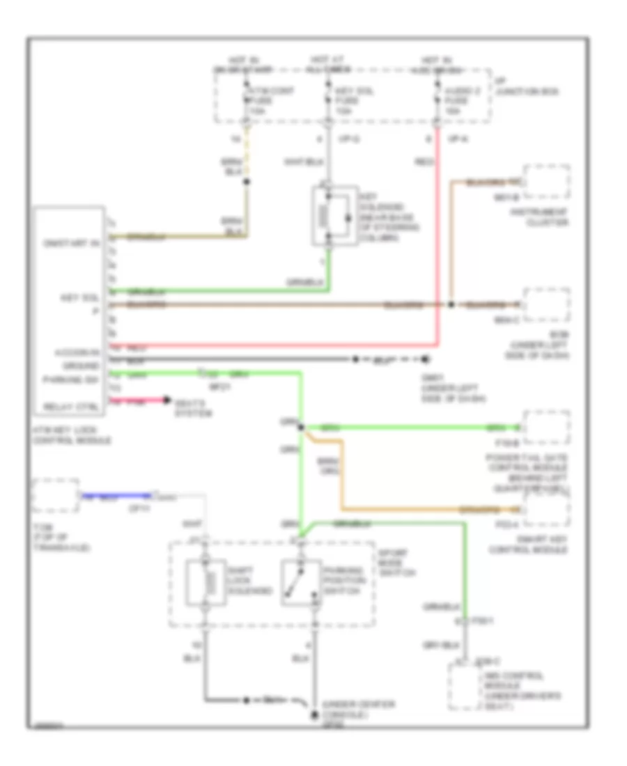 https://portal-diagnostov.com/license.html
Automotive Electricians Portal FZCO
Automotive Electricians Portal FZCO
https://portal-diagnostov.com/license.html
https://portal-diagnostov.com/license.html
Automotive Electricians Portal FZCO
Automotive Electricians Portal FZCOList of elements for Shift Interlock Wiring Diagram for Hyundai Veracruz Limited 2012:
- (under center console) gf02
- Acc/on in
- Atm cont fuse 10a
- Atm key lock control module
- Audio 2 fuse 10a
- Bcm (under left side of dash)
- Cf11
- F19-b
- F53-a
- Fs01
- Gm01 (under left side of dash)
- Ground
- Hot at all times
- Hot in acc or on
- Hot in on or start
- I/p junction box
- I/p-g
- I/p-k
- Ims control module (under driver's seat)
- Instrument cluster
- Key sol
- Key sol fuse 10a
- Key solenoid (near base of steering column)
- M01-b
- M04-c
- Mf21
- On/start in
- Parking position switch
- Parking sw
- Pnk
- Power tail gate control module (behind left quarterpanel)
- Red
- Relay ctrl
- S38-c
- Seats system
- Shift lock solenoid
- Smart key control module
- Sport mode switch
- Tcm (top of transaxle)
STARTING/CHARGING
Charging Wiring Diagram for Hyundai Veracruz Limited 2012
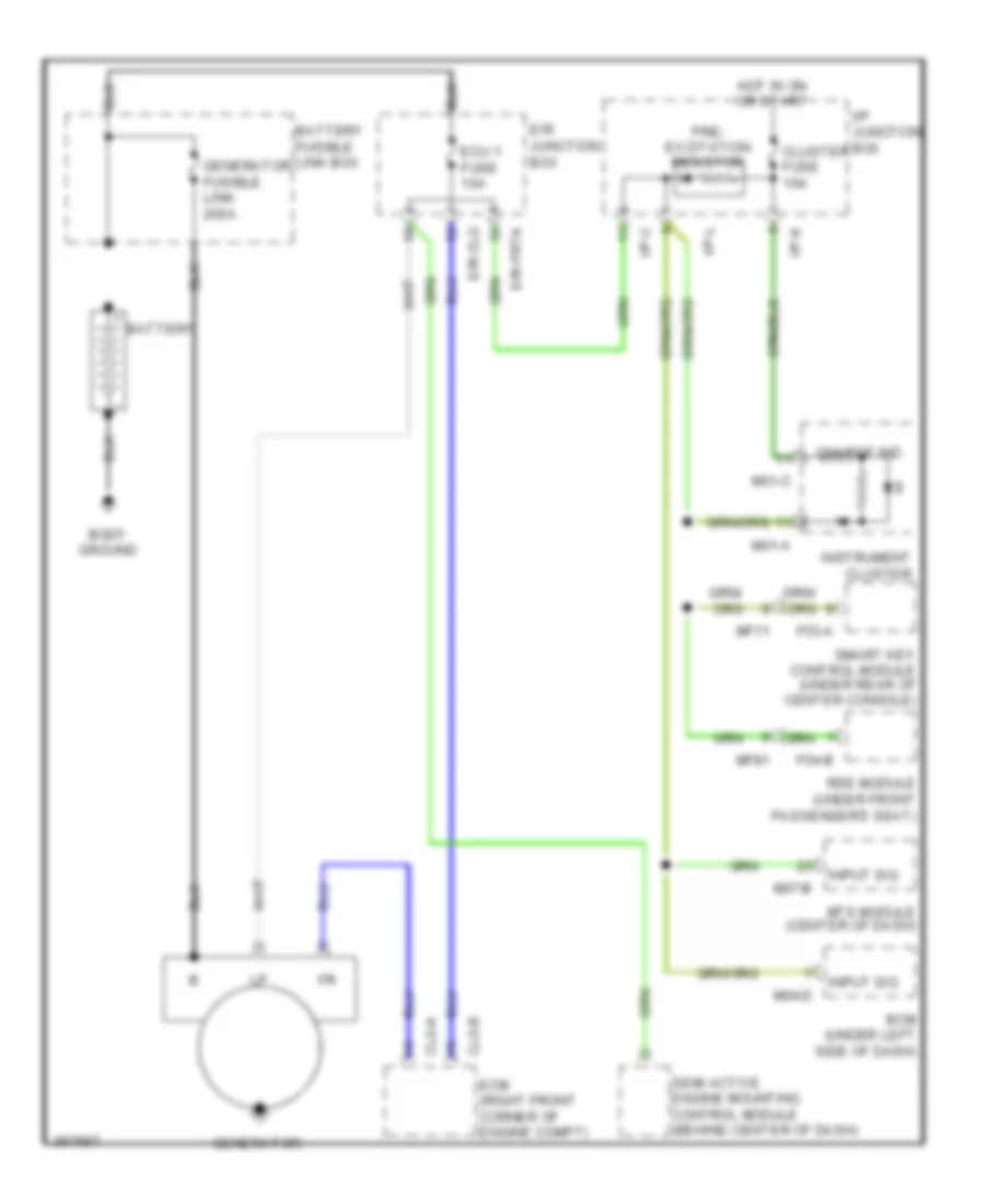 https://portal-diagnostov.com/license.html
Automotive Electricians Portal FZCO
Automotive Electricians Portal FZCO
https://portal-diagnostov.com/license.html
https://portal-diagnostov.com/license.html
Automotive Electricians Portal FZCO
Automotive Electricians Portal FZCOList of elements for Charging Wiring Diagram for Hyundai Veracruz Limited 2012:
- Battery
- Battery fusible link box
- Bcm (under left side of dash)
- Body ground
- Charge ind
- Clg-a
- Clg-b
- Cluster fuse 10a
- E/r junction box
- E/r-clg
- E/r-frta
- Ecm (right front corner of engine compt)
- Ecu 1 fuse 10a
- F53-a
- F54-b
- Generator
- Generator fusible link 200a
- Hot in on or start
- I/p junction box
- I/p-c
- I/p-k
- I/p-l
- Input sig
- Instrument cluster
- M01-a
- M01-c
- M04-d
- M07-b
- Mf11
- Mf81
- Mts module (center of dash)
- Pre- excitation resistor
- Rse module (under front passenger's seat)
- Semi active engine mounting control module (behind center of dash)
- Smart key control module (under rear of center console)
Starting Wiring Diagram for Hyundai Veracruz Limited 2012
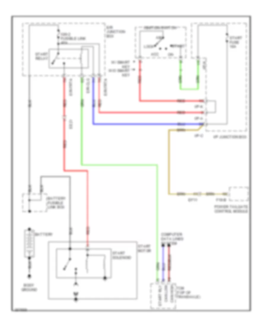 https://portal-diagnostov.com/license.html
Automotive Electricians Portal FZCO
Automotive Electricians Portal FZCO
https://portal-diagnostov.com/license.html
https://portal-diagnostov.com/license.html
Automotive Electricians Portal FZCO
Automotive Electricians Portal FZCOList of elements for Starting Wiring Diagram for Hyundai Veracruz Limited 2012:
- Acc
- Battery
- Battery fusible link box
- Body ground
- Can high
- Can low
- Computer data lines system
- E/r junction box
- E/r-clg
- E/r-frta
- Ee21
- Ef11
- F19-b
- I/p junction box
- I/p-a
- I/p-c
- I/p-k
- Ign 2 fusible link 40a
- Ignition switch
- Lock
- Power tailgate control module
- Red
- Start
- Start fuse 10a
- Start motor
- Start relay
- Start rly
- Start solenoid
- Tcm (top of transaxle)
- W/ smart key w/o smart key
SUPPLEMENTAL RESTRAINTS
Supplemental Restraints Wiring Diagram (1 of 2) for Hyundai Veracruz Limited 2012
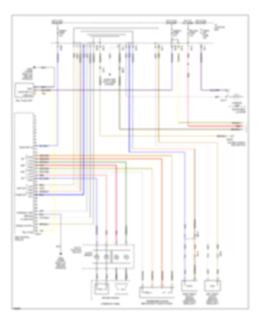 https://portal-diagnostov.com/license.html
Automotive Electricians Portal FZCO
Automotive Electricians Portal FZCO
https://portal-diagnostov.com/license.html
https://portal-diagnostov.com/license.html
Automotive Electricians Portal FZCO
Automotive Electricians Portal FZCOList of elements for Supplemental Restraints Wiring Diagram (1 of 2) for Hyundai Veracruz Limited 2012:
- 1st
- 2nd
- A/bag 1 fuse 15a
- A/bag 2 fuse 10a
- A/bag ind fuse 10a
- A05-a
- Clock spring
- Computer data lines system
- Crash output
- D03-b
- Driver air bag
- Drv fis
- Ec11
- Ee31
- Fd11
- Ga02 (under front of center console)
- Gnd
- Ground
- High
- Hot at all times
- Hot in on or start
- I/p junction box
- I/p-c
- I/p-d
- I/p-g
- I/p-h
- I/p-j
- I/p-l
- I/p-m
- Instrument cluster
- K-line/wcs
- Key sol fuse 10a
- Left front impact sensor (near left headlight)
- Low
- M01-a
- Mc41
- Mf21
- Module
- Multi- function switch
- Nca
- On/start in
- Pass fis
- Passenger air bag (behind right side of dash)
- Pnk
- Power window main switch
- Red
- Right front impact sensor (near right headlight)
- Srs control module
- Steering wheel
- Telltale
- Telltale lamp
- Warning lamp
Supplemental Restraints Wiring Diagram (2 of 2) for Hyundai Veracruz Limited 2012
 https://portal-diagnostov.com/license.html
Automotive Electricians Portal FZCO
Automotive Electricians Portal FZCO
https://portal-diagnostov.com/license.html
https://portal-diagnostov.com/license.html
Automotive Electricians Portal FZCO
Automotive Electricians Portal FZCOList of elements for Supplemental Restraints Wiring Diagram (2 of 2) for Hyundai Veracruz Limited 2012:
- (at left "b" pillar) driver seat belt pretensioner
- (at right "b" pillar) passenger seat belt pretensioner
- (base of left "c" pillar)
- (base of right "c" pillar)
- (under driver's seat) driver side air bag
- (under front passenger seat) passenger side air bag
- A05-b
- Bcm (under left side of dash)
- Buckle snsr
- Can high
- Can low
- Comm
- Computer data lines system
- Dr seat trk
- Driver curtain air bag
- Driver seat belt buckle switch (under driver seat)
- Driver seat track position sensor (under driver seat)
- Drv
- Fd11
- Fd12
- Ga01 (under center console)
- Ground
- High
- In on/start
- Left front side impact sensor (at left "b" pillar)
- Left rear side impact sensor
- Low
- M04-d
- Ma11
- Memory pwr
- Mf61
- On/start in
- Pass
- Passenger curtain air bag
- Passenger seat belt buckle switch (under front passenger seat)
- Pnk
- Red
- Right front side impact sensor (at right "b" pillar)
- Right rear side impact sensor
- Snsr(+)
- Snsr(-)
- Srs control module
- Warg(+) s/belt
- Weight classification module (under front passenger's seat)
TRANSMISSION
4WD Wiring Diagram for Hyundai Veracruz Limited 2012
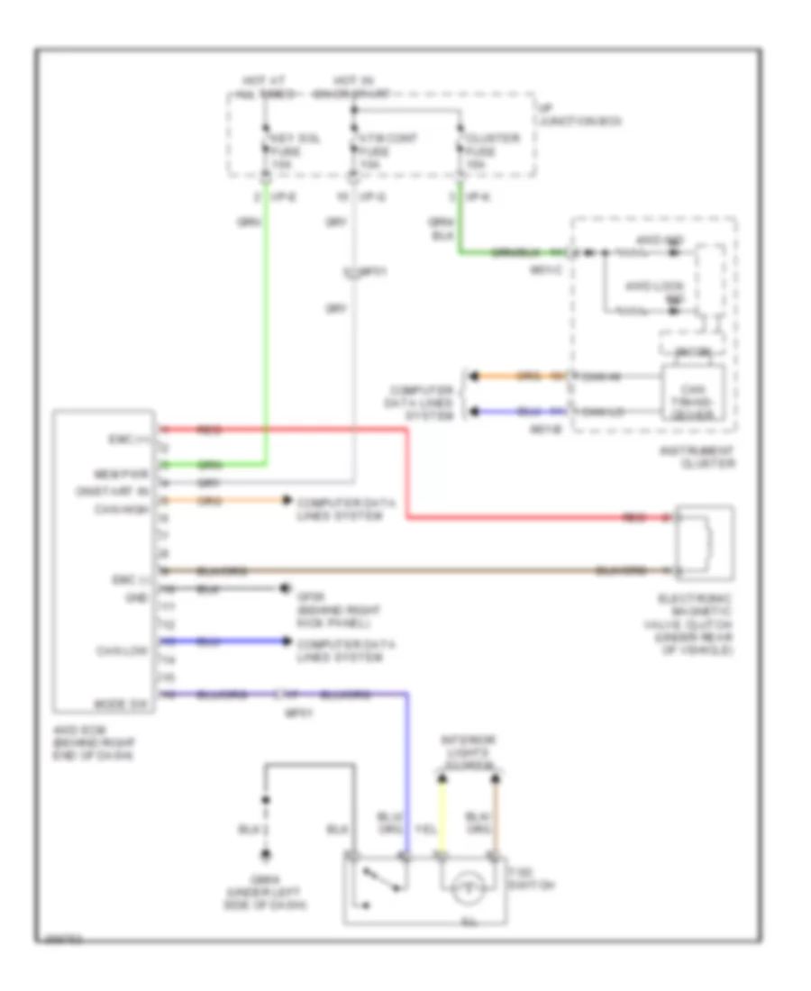 https://portal-diagnostov.com/license.html
Automotive Electricians Portal FZCO
Automotive Electricians Portal FZCO
https://portal-diagnostov.com/license.html
https://portal-diagnostov.com/license.html
Automotive Electricians Portal FZCO
Automotive Electricians Portal FZCOList of elements for 4WD Wiring Diagram for Hyundai Veracruz Limited 2012:
- 4wd ecm (behind right end of dash)
- 4wd ind
- 4wd lock ind
- Atm cont fuse 10a
- Can hi
- Can high
- Can lo
- Can low
- Can trans- ceiver
- Cluster fuse 10a
- Computer data lines system
- Electronic magnetic valve clutch (under rear of vehicle)
- Emc (+)
- Emc (-)
- Gf06 (behind right kick panel)
- Gm04 (under left side of dash)
- Gnd
- Hot at all times
- Hot in on or start
- I/p junction box
- I/p-e
- I/p-g
- I/p-k
- Ill
- Instrument cluster
- Interior lights system
- Key sol fuse 10a
- M01-b
- M01-c
- Mem pwr
- Mf51
- Mf61
- Micom
- Mode sw
- On/start in
- Red
- Tod switch
A/T Wiring Diagram for Hyundai Veracruz Limited 2012
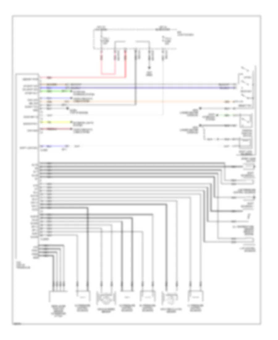 https://portal-diagnostov.com/license.html
Automotive Electricians Portal FZCO
Automotive Electricians Portal FZCO
https://portal-diagnostov.com/license.html
https://portal-diagnostov.com/license.html
Automotive Electricians Portal FZCO
Automotive Electricians Portal FZCOList of elements for A/T Wiring Diagram for Hyundai Veracruz Limited 2012:
- (not used)
- B1 pressure control solenoid
- Backup rly
- C1 pressure control solenoid
- C2 pressure control solenoid
- C3 pressure control solenoid
- Can high
- Can low
- Cf11
- Clg09
- Clg09a
- Computer data lines system
- Down sw
- Dummy tml
- Dw shift sw
- E/r junction box
- E/r-clg
- E/r-frta
- E/r-frtb
- Exterior lights system
- Gear lever position sensor (integrated in tcm)
- Gf02 (under center console)
- Gf05 (under center console)
- Glg04 (top of engine)
- Gnd
- Hot at all times
- Hot in on or start
- Input revolution sensor
- L-up control solenoid
- Line pressure control solenoid
- Memory pwr
- Nca
- Nin (+)
- Nin (-)
- Oil temperature sensor (rear of engine)
- On/start in
- Otg
- Parking position switch
- Pos1
- Pos2
- Red
- Sel sw
- Select sw
- Shift interlock system
- Shift lock sol
- Shift lock solenoid
- Shift solenoid 1
- Shift solenoid 2
- Slb1
- Slb1g
- Slc1
- Slc1g
- Slc2
- Slc2g
- Slc3
- Slc3g
- Slt
- Sltg
- Slu
- Slug
- Sp (+)
- Sp (-)
- Sport mode switch
- Start rly
- Starting/ charging system
- Tcm (top of transaxle)
- Tcu 1 fuse 15a
- Tcu 2 fuse 10a
- Up shift sw
- Up sw
- Vcc
- Vehicle speed sensor
TRUNK, TAILGATE, FUEL DOOR
Fuel Door Release Wiring Diagram for Hyundai Veracruz Limited 2012
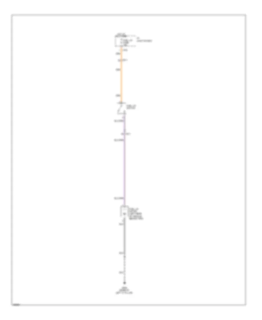 https://portal-diagnostov.com/license.html
Automotive Electricians Portal FZCO
Automotive Electricians Portal FZCO
https://portal-diagnostov.com/license.html
https://portal-diagnostov.com/license.html
Automotive Electricians Portal FZCO
Automotive Electricians Portal FZCOList of elements for Fuel Door Release Wiring Diagram for Hyundai Veracruz Limited 2012:
- Fd11
- Fuel lid fuse 15a
- Fuel lid motor (left rear of vehicle, behind trim)
- Fuel lid switch
- Gf08 (base of left "c" pillar)
- Hot at all times
- I/p junction box
- I/p-e
Power Tailgate Wiring Diagram (1 of 2) for Hyundai Veracruz Limited 2012
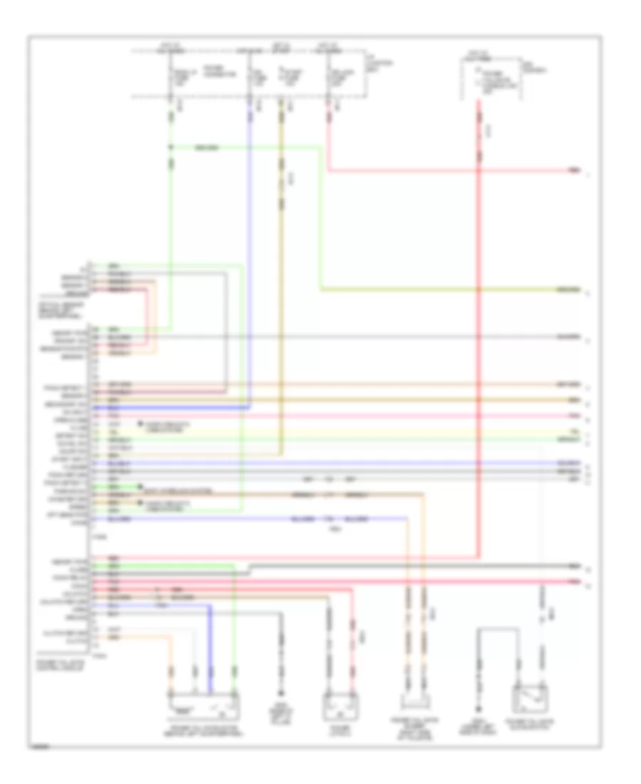 https://portal-diagnostov.com/license.html
Automotive Electricians Portal FZCO
Automotive Electricians Portal FZCO
https://portal-diagnostov.com/license.html
https://portal-diagnostov.com/license.html
Automotive Electricians Portal FZCO
Automotive Electricians Portal FZCOList of elements for Power Tailgate Wiring Diagram (1 of 2) for Hyundai Veracruz Limited 2012:
- Cf11
- Chime
- Chime return
- Cinch
- Cinch relax
- Close
- Clutch
- Clutch return
- Computer data lines system
- Detent sw
- Dr lock fuse 20a
- E/r sub box
- Ef11
- F19-a
- F19-b
- Flasher
- Fr21
- Fr41
- Gf08 (base of left "c" pillar)
- Gm04 (under left side of dash)
- Ground
- Hot at all times
- Hot in on
- Hot in start
- I/p junction box
- I/p-c
- I/p-d
- I/p-e
- I/p-j
- Ims fuse 10a
- K-line
- Memory pwr
- Mf21
- Nca
- O/s hdl sw
- On input
- On/off sw
- Open
- Open/close
- Opt sens pwr
- Optical sensor (behind left quarterpanel)
- Parking sw
- Pinch detect 1
- Pinch detect 2
- Pinch return
- Pnk
- Power connector
- Power latch 2
- Power tail gate buzzer (right side of tailgate)
- Power tail gate control module
- Power tail gate glove switch
- Power tail gate motor (behind left quarterpanel)
- Power tail/gate fusible link 30a
- Primary sw
- Red
- Room lp fuse 15a
- Rr11
- Rr21
- Secondary sw
- Sensor 1
- Sensor 2
- Sensor pwr rtn
- Shift interlock system
- Speed
- Start fuse 10a
- Start input
- Unlatch
- Unlatch return
Power Tailgate Wiring Diagram (2 of 2) for Hyundai Veracruz Limited 2012
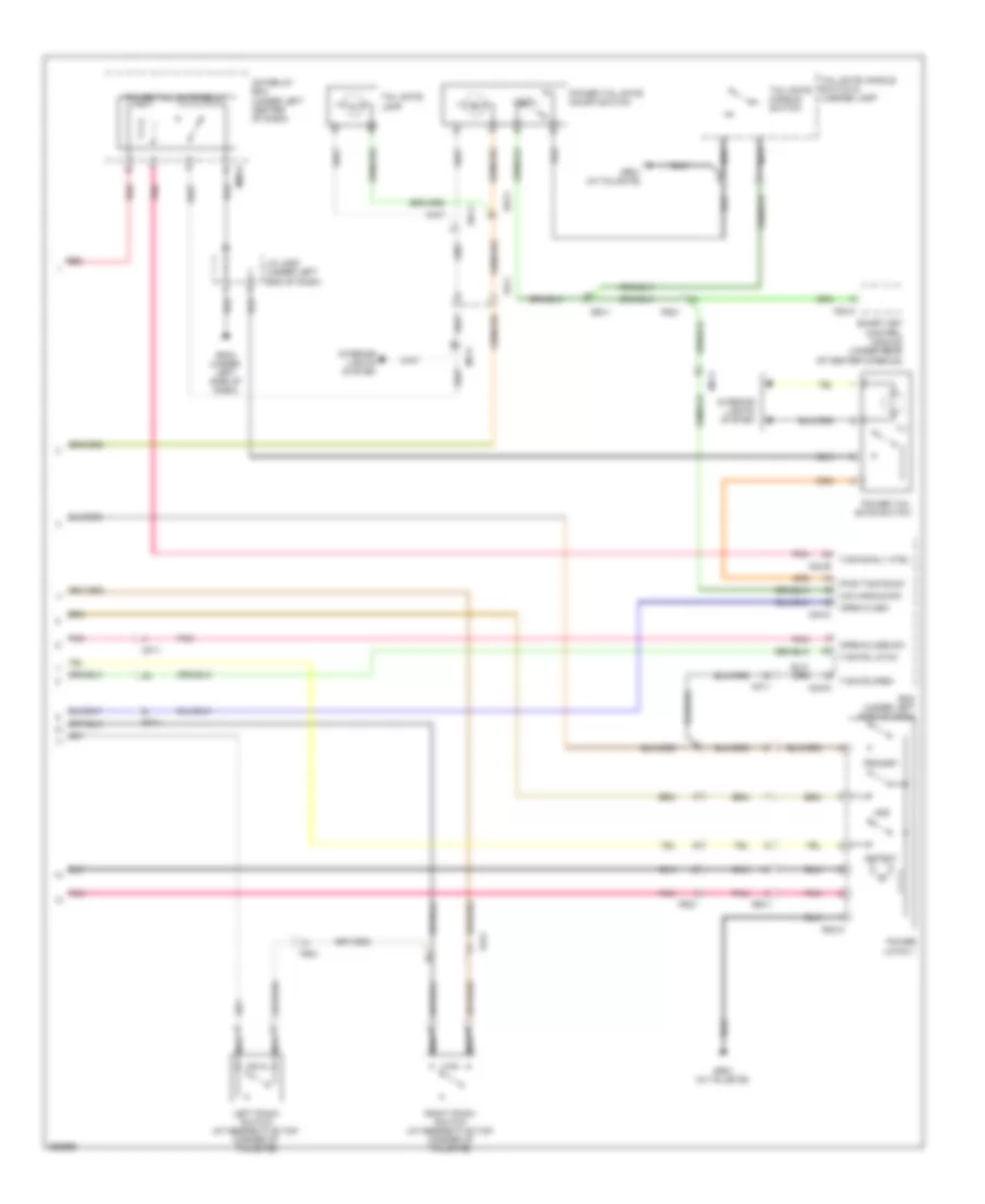 https://portal-diagnostov.com/license.html
Automotive Electricians Portal FZCO
Automotive Electricians Portal FZCO
https://portal-diagnostov.com/license.html
https://portal-diagnostov.com/license.html
Automotive Electricians Portal FZCO
Automotive Electricians Portal FZCOList of elements for Power Tailgate Wiring Diagram (2 of 2) for Hyundai Veracruz Limited 2012:
- 2nd
- Bcm (under left side of dash)
- Detent
- F53-a
- Fr11
- Fr21
- Fr41
- Gm04 (under left side of dash)
- Gr01 (in tailgate)
- Icm relay box (under left center of dash)
- Ill
- Interior lights system
- J/c jm05 (under left end of dash)
- Left pinch switch (at respective top corner of tailgate)
- Local
- M04-b
- M04-c
- M04-d
- M08-a
- Mf11
- Mf41
- Nca
- O/s handle sw
- Open flash
- Open/close sw
- Pnk
- Power latch 1
- Power tail gate on/off switch
- Power tail gate relay
- Power tail gate switch
- Primary
- Pwr t/gate sw
- R02-a
- Red
- Right pinch switch (at respective top corner of tailgate)
- Rr11
- Smart key control module (under rear of center console)
- T/gate latch
- T/gate open
- T/gate rly ctrl
- Tail gate handle switch
- Tail gate handle switch & license lamp
- Tail gate lamp
WARNING SYSTEMS
Chime Wiring Diagram for Hyundai Veracruz Limited 2012
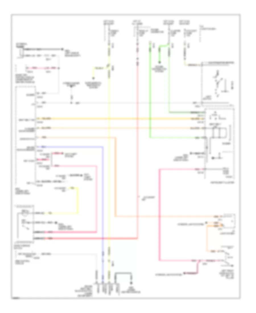 https://portal-diagnostov.com/license.html
Automotive Electricians Portal FZCO
Automotive Electricians Portal FZCO
https://portal-diagnostov.com/license.html
https://portal-diagnostov.com/license.html
Automotive Electricians Portal FZCO
Automotive Electricians Portal FZCOList of elements for Chime Wiring Diagram for Hyundai Veracruz Limited 2012:
- A/bag 2 fuse 10a
- A05-b
- Anti- theft system
- Anti-theft system
- Atm cont fuse 10a
- Auto
- Bcm (under left side of dash)
- Buzzer
- Cluster fuse 10a
- Door switch
- Door warning switch
- Driver buckle sensor
- Driver seat belt buckle switch (under driver seat)
- Drv buckle sens
- Em11
- External buzzer
- F53-a
- Flasher sound buzzer
- Fr-lh door ajar
- Ga01 (under center console)
- Ge01 (left side of engine compt)
- Gm01 (under left side of dash)
- Gm04 (under left side of dash)
- Hot at all times
- Hot in on or start
- I/p junction box
- I/p-d
- I/p-f
- I/p-g
- I/p-h
- I/p-j
- I/p-k
- Instrument cluster
- Interior lights system
- Key
- Key ill
- Key in sw
- Key switch
- Left front door switch (at left ``b" pillar)
- Light switch
- Lin
- M/f ecu
- M01-b
- M01-c
- M02-l
- M04-b
- M04-c
- M04-d
- Ma11
- Mf41
- Mf61
- Micom
- Multi-function switch
- Nca
- Off
- On/start input
- Pnk
- Power connector
- Power distribution system
- Red
- Room lp fuse 15a
- S/belt warg (+)
- Seat belt ind
- Smart key control module (under rear of center console)
- Snsr (+)
- Snsr (-)
- Srs control module
- W/ smart key
- W/o smart
- W/o smart key
- Wiper/washer system
Tire Pressure Monitoring Wiring Diagram for Hyundai Veracruz Limited 2012
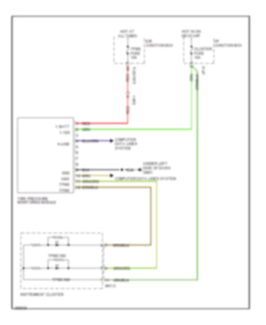 https://portal-diagnostov.com/license.html
Automotive Electricians Portal FZCO
Automotive Electricians Portal FZCO
https://portal-diagnostov.com/license.html
https://portal-diagnostov.com/license.html
Automotive Electricians Portal FZCO
Automotive Electricians Portal FZCOList of elements for Tire Pressure Monitoring Wiring Diagram for Hyundai Veracruz Limited 2012:
- (under left side of dash) gm01
- Cluster fuse 10a
- Computer data lines system
- E/r junction box
- E/r-frta
- Em11
- Gnd
- Hot at all times
- Hot in on or start
- I/p junction box
- I/p-k
- Ign1
- Instrument cluster
- K-line
- M01-c
- Red
- Tire pressure monitoring module
- Tpms
- Tpms fuse 10a
- Tpms ind
- V batt
- V ign
WIPER/WASHER
Front Wiper/Washer Wiring Diagram, with Rain Sensor for Hyundai Veracruz Limited 2012
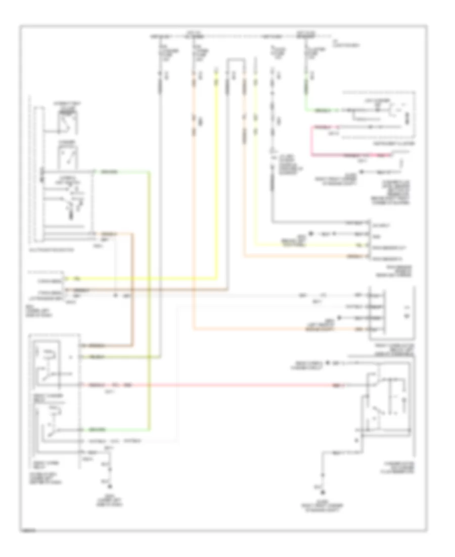 https://portal-diagnostov.com/license.html
Automotive Electricians Portal FZCO
Automotive Electricians Portal FZCO
https://portal-diagnostov.com/license.html
https://portal-diagnostov.com/license.html
Automotive Electricians Portal FZCO
Automotive Electricians Portal FZCOList of elements for Front Wiper/Washer Wiring Diagram, with Rain Sensor for Hyundai Veracruz Limited 2012:
- A/con fuse 10a
- B/up
- Bcm (under left side of dash)
- Cluster fuse 10a
- Em11
- Em31
- F rain sens
- Fr washer fuse 15a
- Fr wiper fuse 30a
- Fr61
- Front washer relay
- Front wiper motor (below left side of windshield)
- Front wiper relay
- Ge03 (left rear of engine compt)
- Gf03 (behind left kick panel)
- Glg02 (right front corner of engine compt)
- Gm04 (under left side of dash)
- Gnd
- Hot at all times
- Hot in on
- Hot in on or start
- I/p junction box
- I/p-f
- I/p-g
- I/p-h
- I/p-k
- Icm relay box (under left center of dash)
- Instrument cluster
- Int
- Intermittent volume switch
- J/c jr01 (in roof console, forward of sunroof)
- Lin
- Lin transceiver
- Low washer ind
- M/f ecu
- M01-c
- M02-l
- M04-c
- M08-a
- Mc11
- Micom
- Mist
- Multifunction switch
- O rain sens
- Off
- On input
- Pnk
- Rain sensor (base of rearview mirror)
- Rain sensor in
- Rain sensor out
- Rear wiper & washer circuit
- Red
- Washer fluid level sensor (bottom of reservoir, behind right front corner of bumper)
- Washer motor (on washer fluid reservoir)
- Washer switch
- Wiper & mist switch
Front Wiper/Washer Wiring Diagram, without Rain Sensor for Hyundai Veracruz Limited 2012
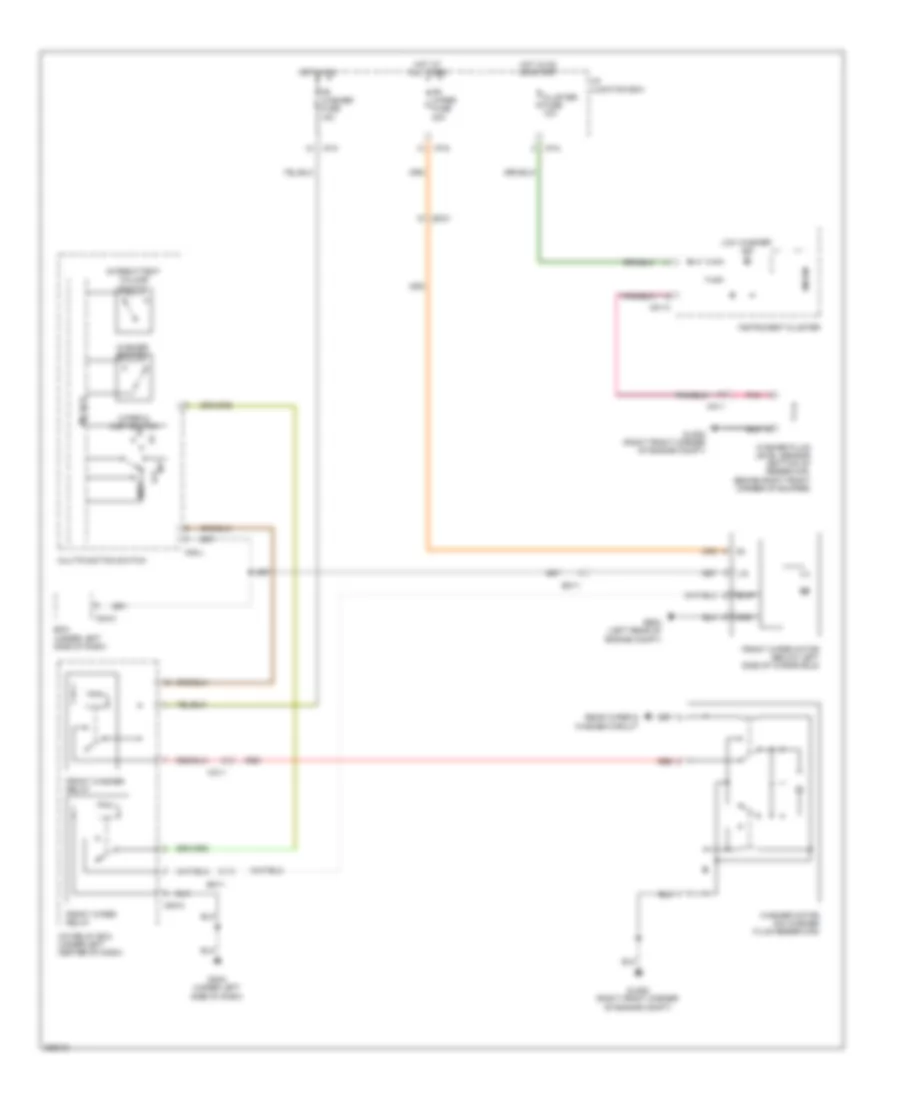 https://portal-diagnostov.com/license.html
Automotive Electricians Portal FZCO
Automotive Electricians Portal FZCO
https://portal-diagnostov.com/license.html
https://portal-diagnostov.com/license.html
Automotive Electricians Portal FZCO
Automotive Electricians Portal FZCOList of elements for Front Wiper/Washer Wiring Diagram, without Rain Sensor for Hyundai Veracruz Limited 2012:
- B/up
- Bcm (under left side of dash)
- Cluster fuse 10a
- Em11
- Em31
- Fr washer fuse 15a
- Fr wiper fuse 30a
- Front washer relay
- Front wiper motor (below left side of windshield)
- Front wiper relay
- Ge03 (left rear of engine compt)
- Glg02 (right front corner of engine compt)
- Gm04 (under left side of dash)
- Gnd
- Hot at all times
- Hot in on
- Hot in on or start
- I/p junction box
- I/p-g
- I/p-k
- Icm relay box (under left center of dash)
- Instrument cluster
- Int
- Intermittent volume switch
- Lin
- Low washer ind
- M/f ecu
- M01-c
- M02-l
- M04-c
- M08-a
- Mc11
- Micom
- Mist
- Multifunction switch
- Off
- Pnk
- Rear wiper & washer circuit
- Red
- Washer fluid level sensor (bottom of reservoir, behind right front corner of bumper)
- Washer motor (on washer fluid reservoir)
- Washer switch
- Wiper & mist switch
Rear Wiper/Washer Wiring Diagram for Hyundai Veracruz Limited 2012
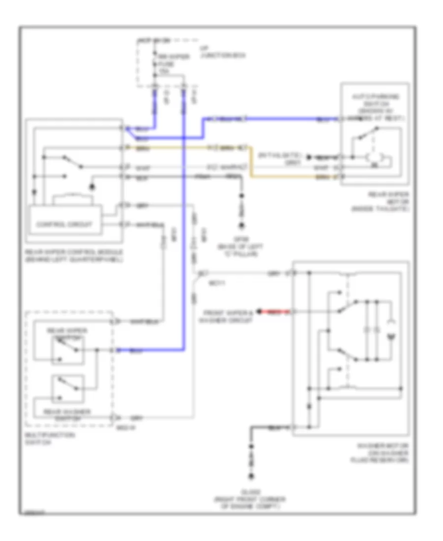 https://portal-diagnostov.com/license.html
Automotive Electricians Portal FZCO
Automotive Electricians Portal FZCO
https://portal-diagnostov.com/license.html
https://portal-diagnostov.com/license.html
Automotive Electricians Portal FZCO
Automotive Electricians Portal FZCOList of elements for Rear Wiper/Washer Wiring Diagram for Hyundai Veracruz Limited 2012:
- (in tailgate) gr01
- Auto parking switch (shown w/ wipers at rest)
- Control circuit
- Fr41
- Front wiper & washer circuit
- Gf08 (base of left "c" pillar)
- Glg02 (right front corner of engine compt)
- Hot in on
- I/p junction box
- I/p-d
- I/p-h
- M02-w
- Mc11
- Mf61
- Multifunction switch
- Rear washer switch
- Rear wiper control module (behind left quarterpanel)
- Rear wiper motor (inside tailgate)
- Rear wiper switch
- Red
- Rr wiper fuse 15a
- Rr21
- Washer motor (on washer fluid reservoir)

 Čeština
 Dansk
Dansk Deutsch
 Ελληνικά
 English
 English
 Español
 Suomi
Suomi Français
 Français
 עברית
עברית Hrvatski
 Magyar
 Italiano
 日本語
日本語 한국어
한국어 Nederlands
 Polski
 Português
 Português
 Română
 Русский
 Slovenčina
 Slovenščina
 Svenska
 中文 (中国)
