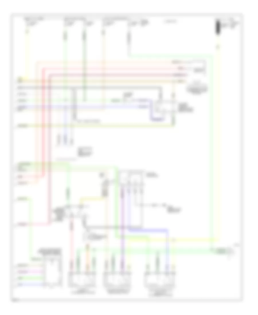
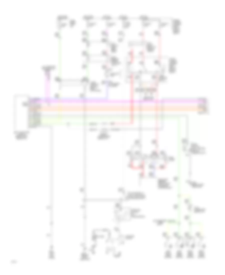
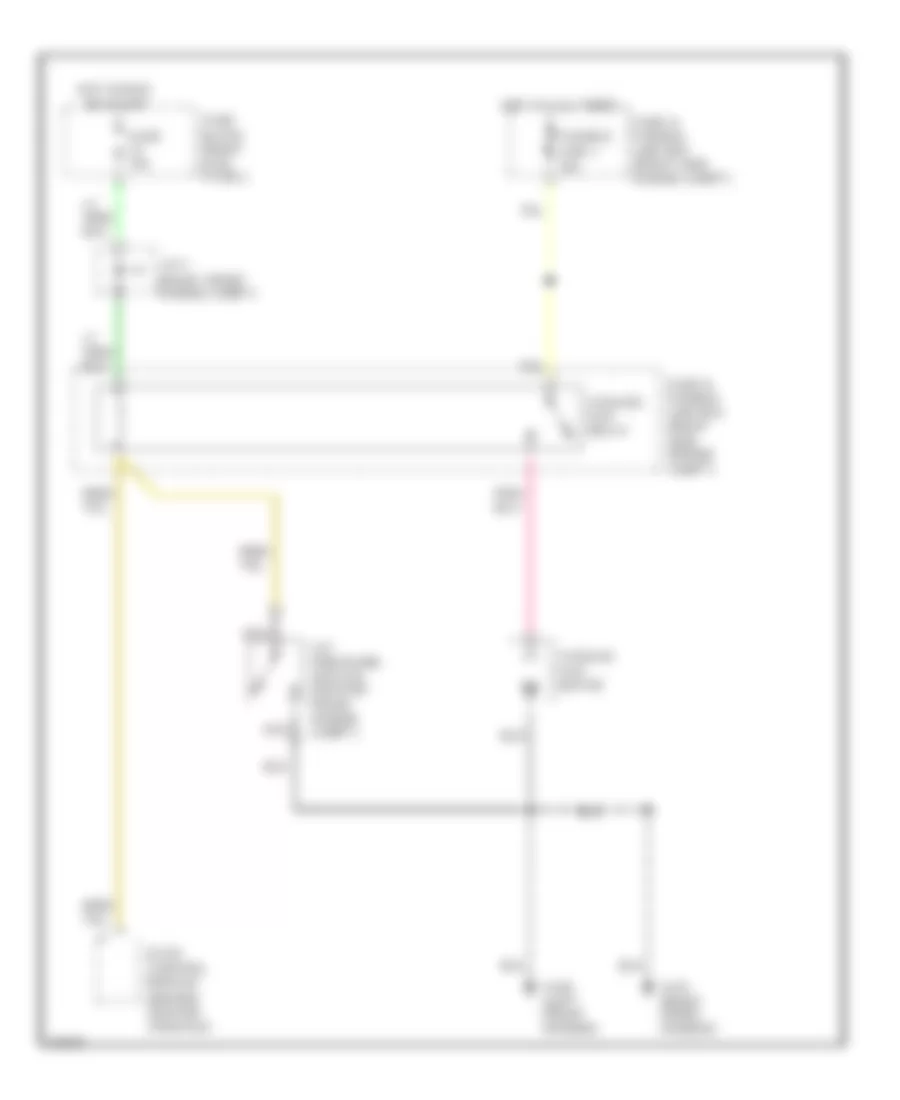
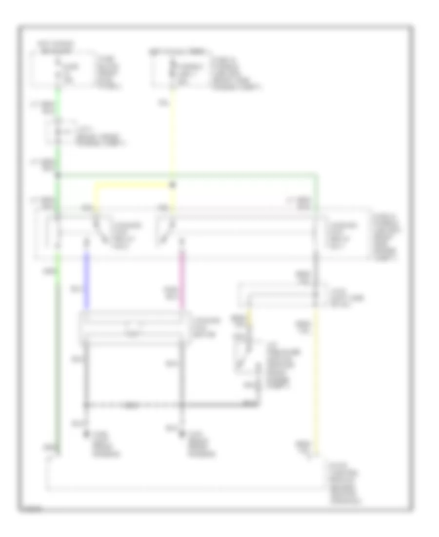
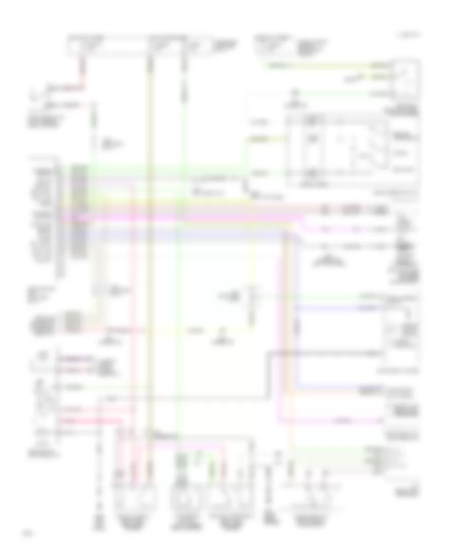
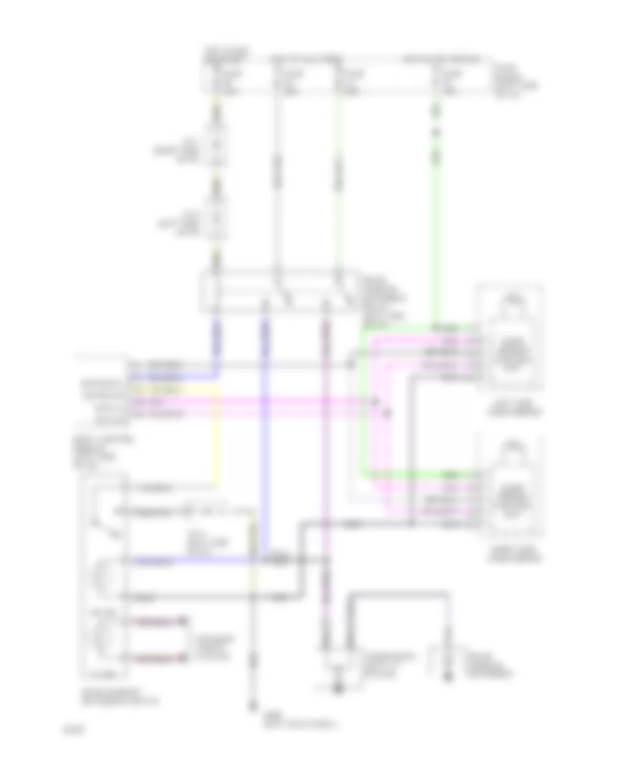
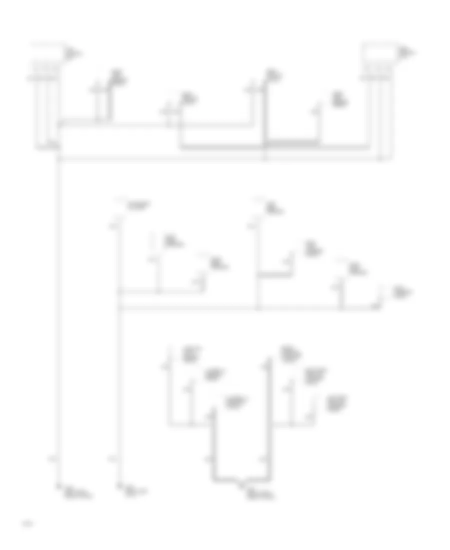
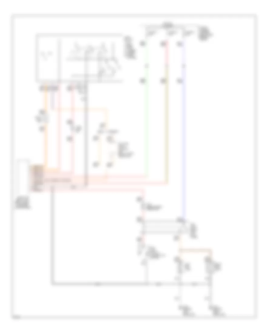
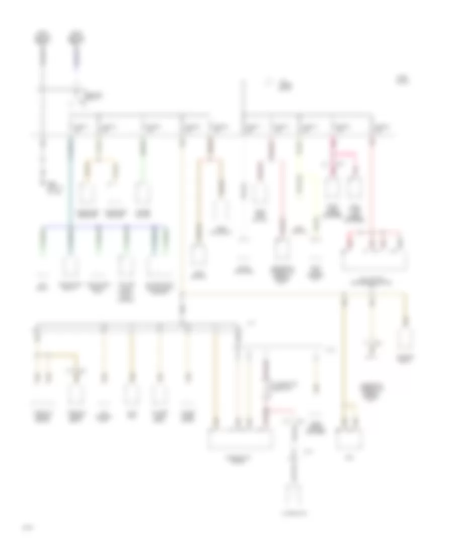
AIR CONDITIONING
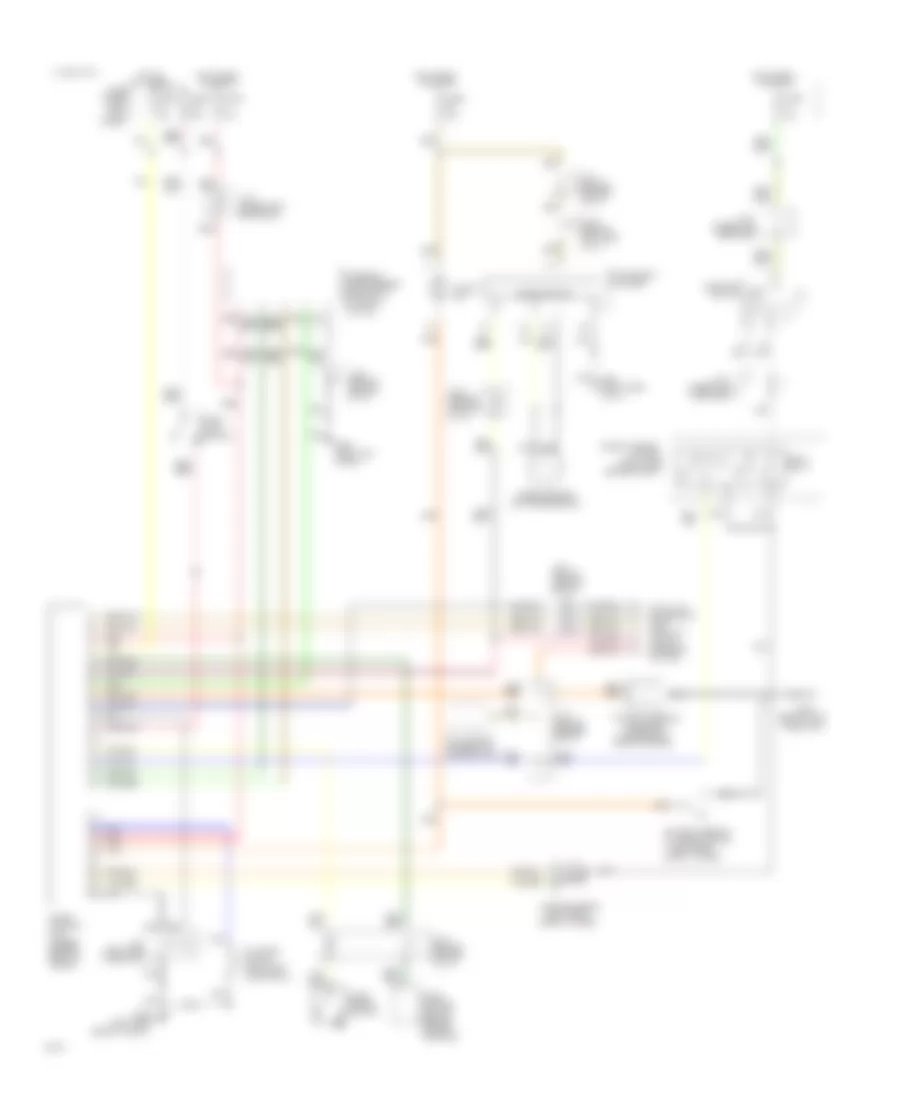
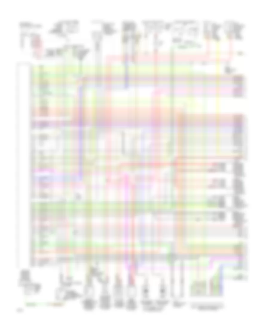
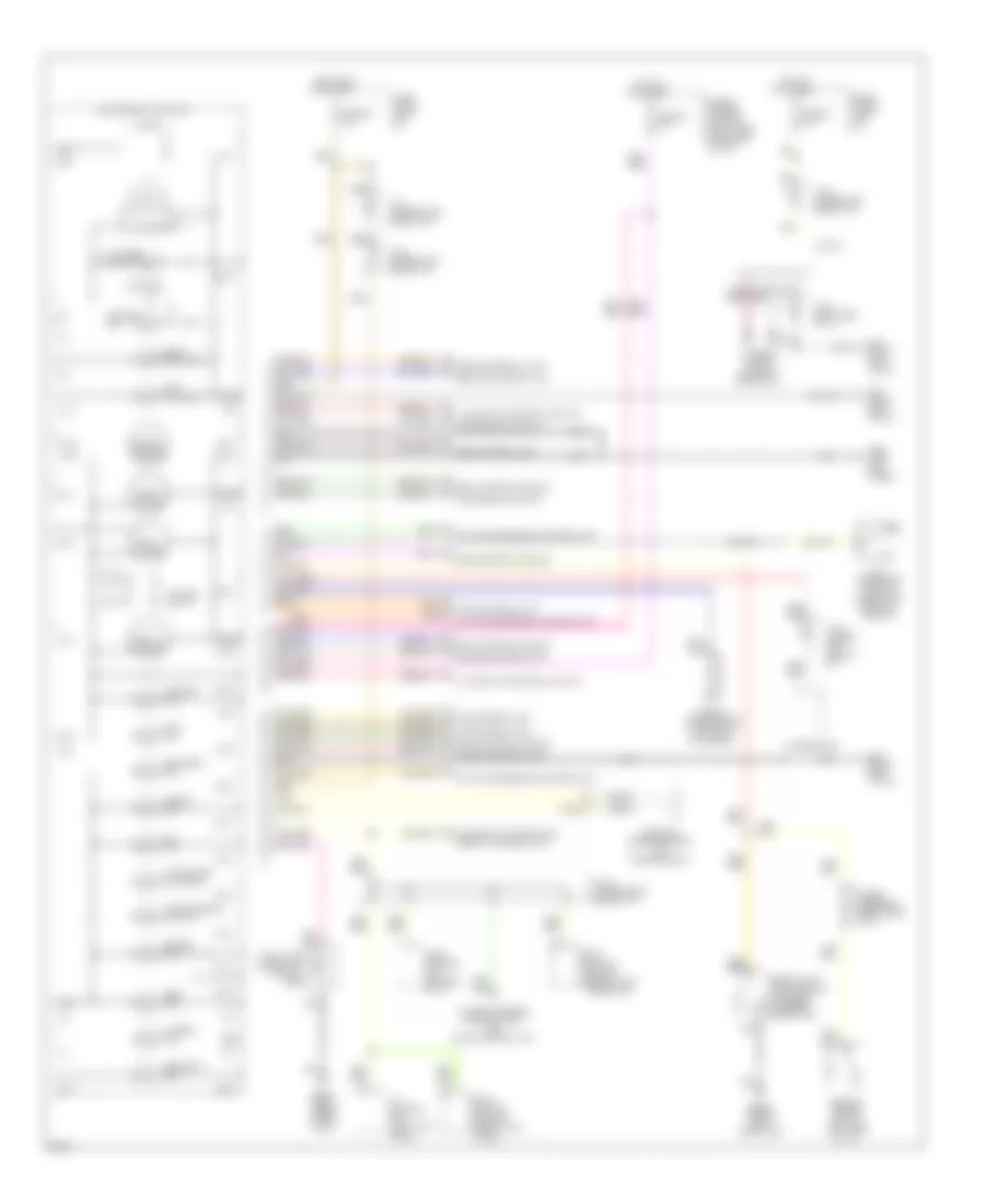
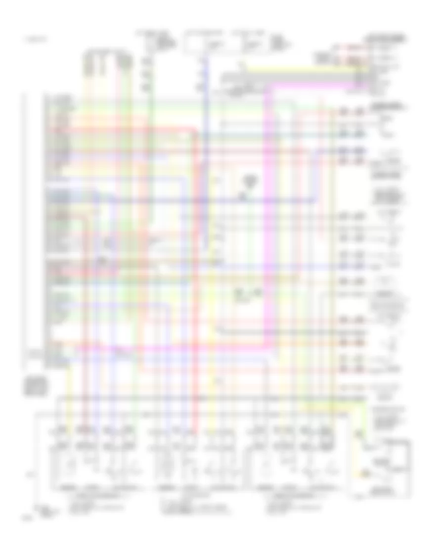
Air Conditioning Wiring Diagrams (1 of 2) for Infiniti Q45 1994
 https://portal-diagnostov.com/license.html
Automotive Electricians Portal FZCO
Automotive Electricians Portal FZCO
https://portal-diagnostov.com/license.html
https://portal-diagnostov.com/license.html
Automotive Electricians Portal FZCO
Automotive Electricians Portal FZCO
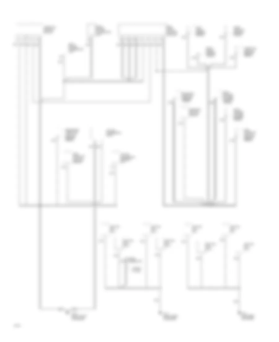
List of elements for Air Conditioning Wiring Diagrams (1 of 2) for Infiniti Q45 1994:
- (front of engine)
- (front of vehicle)
- (left kick panel)
- (right
- 1994 vftc c
- A/c auto amp
- A/c control unit (center of i/p)
- Ambient sensor
- Eccs control module
- G200
- In vehicle sensor (center of i/p)
- Intake sensor (in evaporator case)
- Interior lights system
- J/c #1
- Kick panel)
- Mode door motor
- Mode door motor (behind left side of center console)
- Position switch
- Radio
- Red
- Sunload sensor (center of dash)
- Thermal transmitter
- Water temperature sensor (on heater unit)
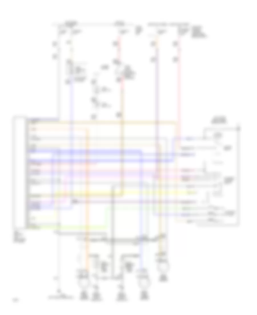
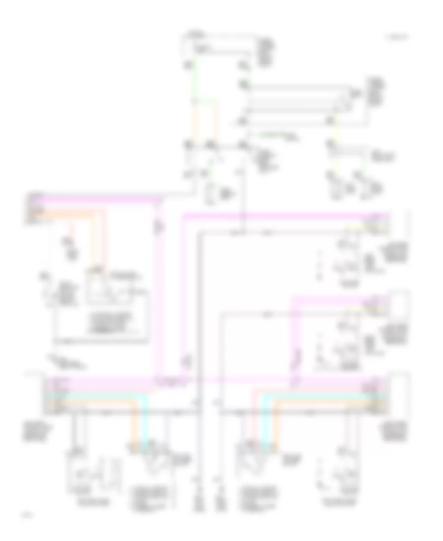
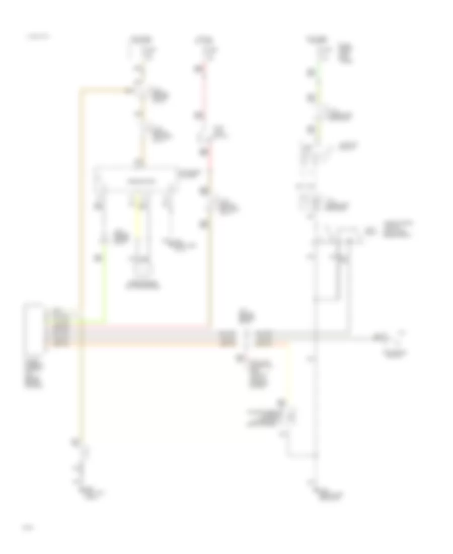
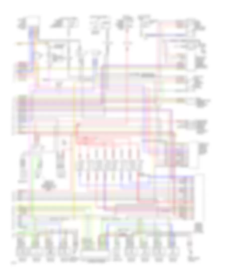
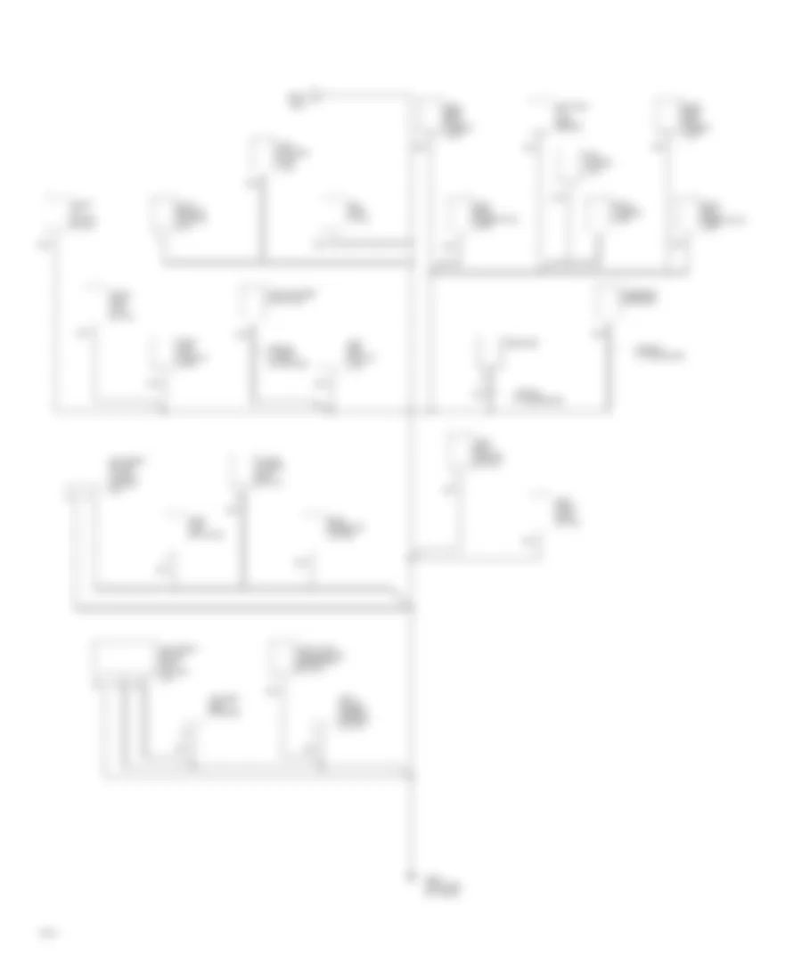
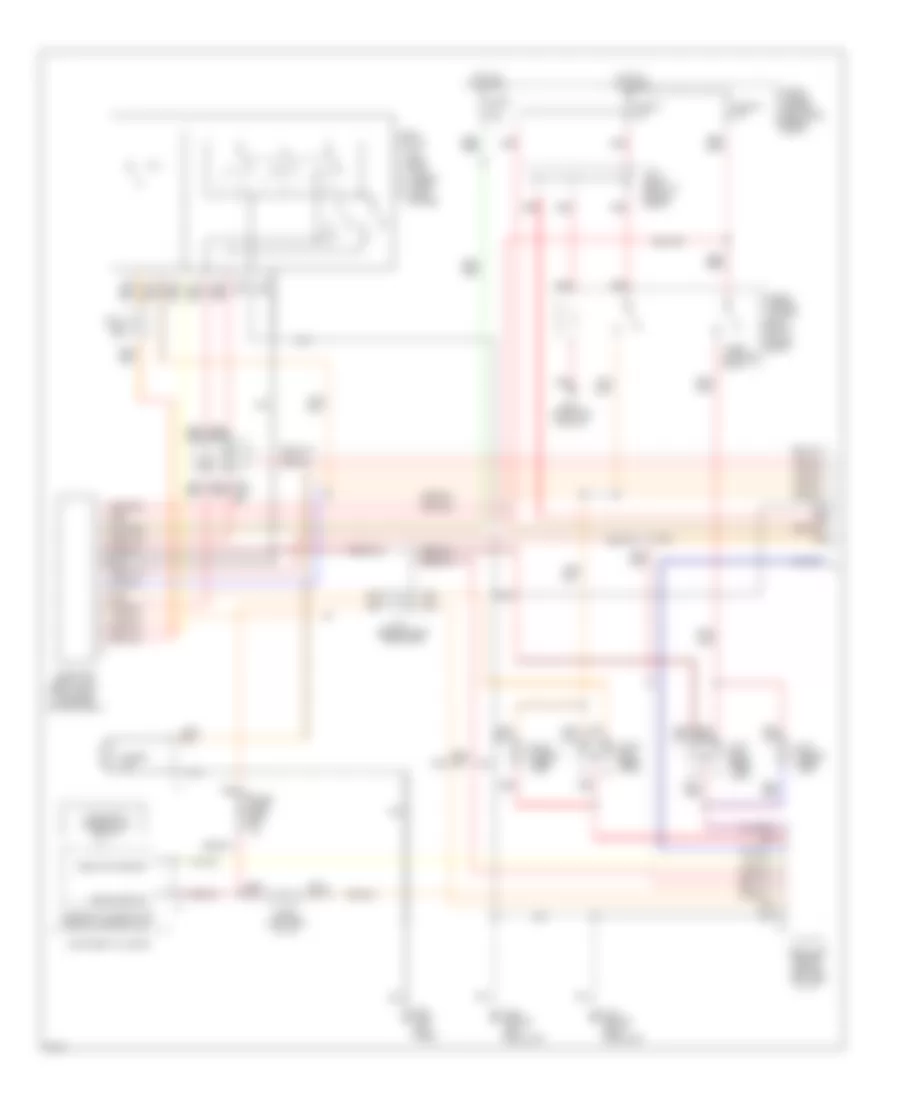
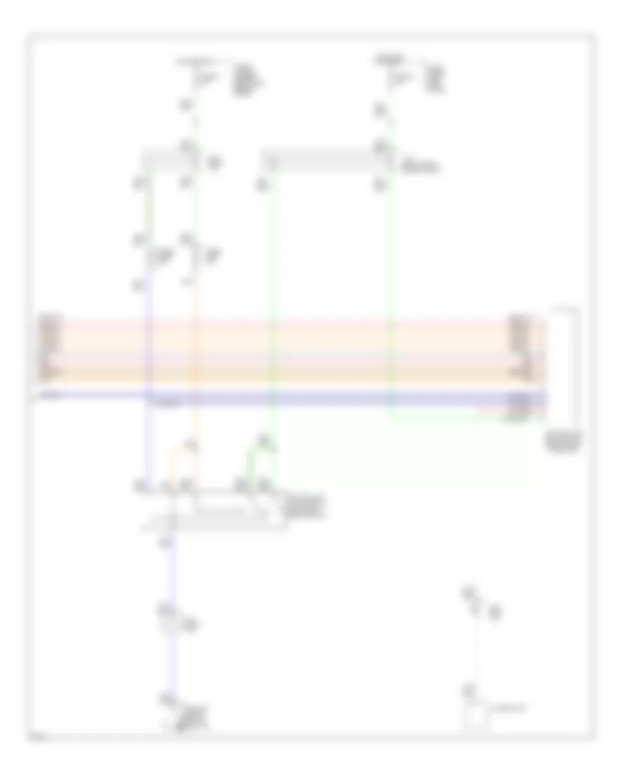
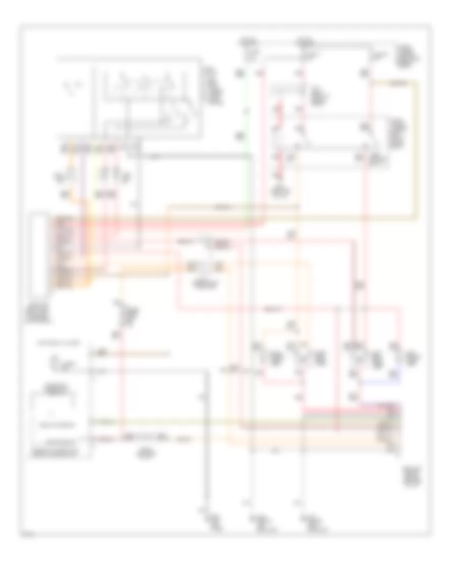
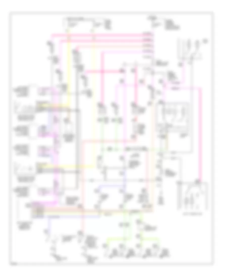
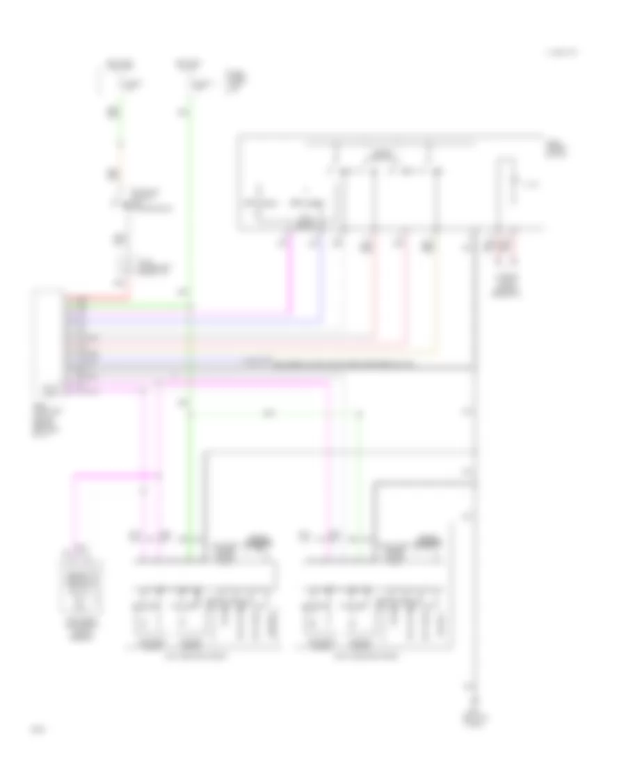
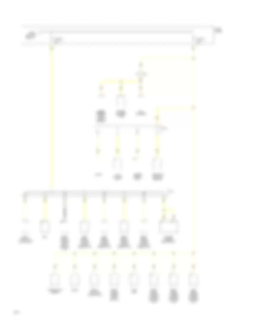
Air Conditioning Wiring Diagrams (2 of 2) for Infiniti Q45 1994
 https://portal-diagnostov.com/license.html
Automotive Electricians Portal FZCO
Automotive Electricians Portal FZCO
https://portal-diagnostov.com/license.html
https://portal-diagnostov.com/license.html
Automotive Electricians Portal FZCO
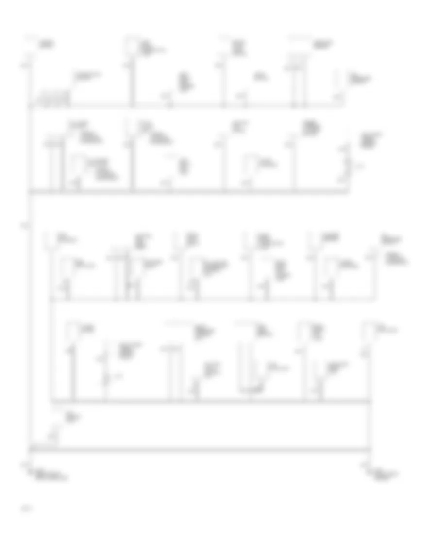
Automotive Electricians Portal FZCOList of elements for Air Conditioning Wiring Diagrams (2 of 2) for Infiniti Q45 1994:
- (right of dash)
- (usa only) (in fuse/relay block)
- 1994 vftc c
- A/c compressor clutch
- A/c relay (in fuse/relay block)
- Air mix door motor (behind right side of center console)
- Blower hi relay (behind right side of dash)
- Blower motor
- Cooling fan motor
- Cooling fan relay #1 (near hood latch)
- Cooling fan relay #2
- Fan control amp (behind right side of i/p)
- Fuse 13 10a
- Fuse 21 10a
- Fuse 25 10a
- Fuse 7 15a
- Fuse 8 15a
- Fuse block: i/p
- Fusible link box
- Fusible link l
- G106 (behind left headlight)
- G201
- Hot at all times
- Hot at all times
- Hot in accy or on
- Hot in on or start
- Intake door motor (under right side of dash)
- J/c
- J/c #1
- Position switch
- Red
- Triple pressure switch (right front of engine)
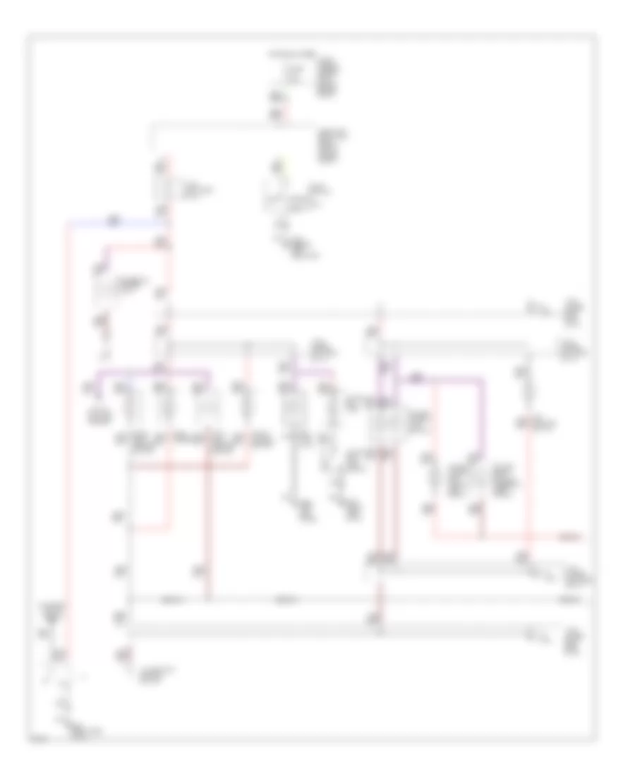
ANTI-LOCK BRAKES
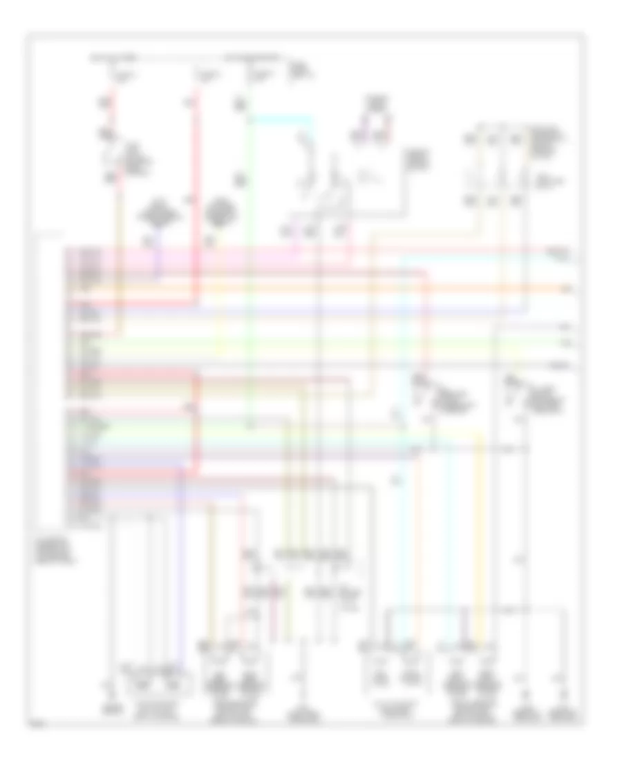
Anti-Lock Brakes Wiring Diagram for Infiniti Q45 1994
 https://portal-diagnostov.com/license.html
Automotive Electricians Portal FZCO
Automotive Electricians Portal FZCO
https://portal-diagnostov.com/license.html
https://portal-diagnostov.com/license.html
Automotive Electricians Portal FZCO
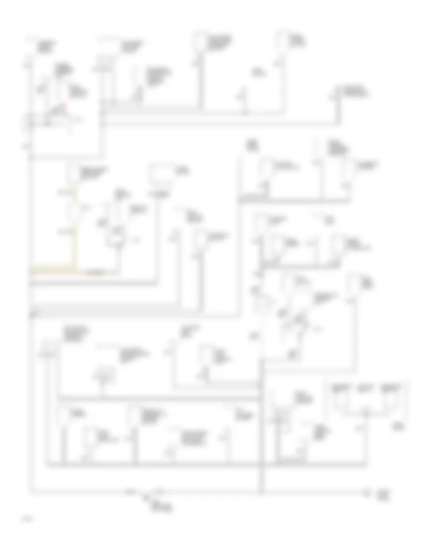
Automotive Electricians Portal FZCOList of elements for Anti-Lock Brakes Wiring Diagram for Infiniti Q45 1994:
- (behind
- (left rear wheelwell)
- (right rear
- Abs control
- Abs warning ind.
- Actuator
- All times
- Alter- nator
- Block (left i/p)
- Engine compt)
- Fuse
- Fuse 1 10a
- Fuse 18 15a
- Fuse 25 10a
- Fuse 43 20a
- Fuse and fusible link box (right side engine compt)
- Fusible link b 30a
- G106
- G107
- G402
- Headlight)
- Hot at
- Hot at all times
- Hot in run or start
- Instrument cluster
- J/c-3 (behind right head- lamp)
- J/c-4 (behind left head- lamp)
- J/c-5 (left i/p)
- J/c-6 (left i/p)
- Left
- Left front wheel sensor
- Motor
- Motor relay
- Nca
- Rear wheel sensor
- Right
- Right front wheel sensor
- Solenoid valves
- Solenoid valves relay
- Stop lamp switch (on brake pedal support)
- Unit (left rear of trunk)
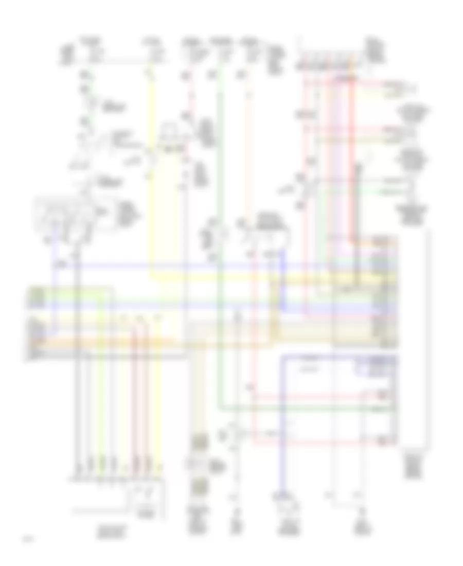
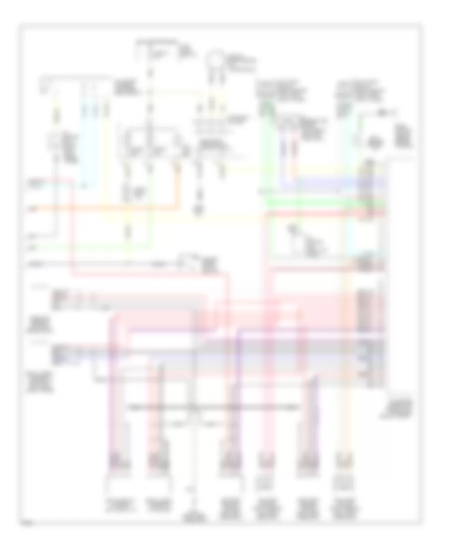
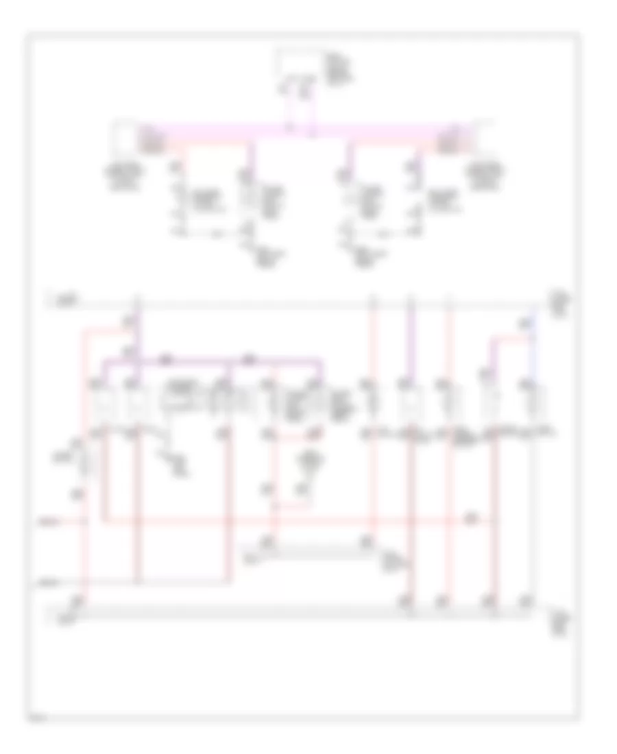
Traction Control Wiring Diagram (2 of 2) for Infiniti Q45 1994
 https://portal-diagnostov.com/license.html
Automotive Electricians Portal FZCO
Automotive Electricians Portal FZCO
https://portal-diagnostov.com/license.html
https://portal-diagnostov.com/license.html
Automotive Electricians Portal FZCO
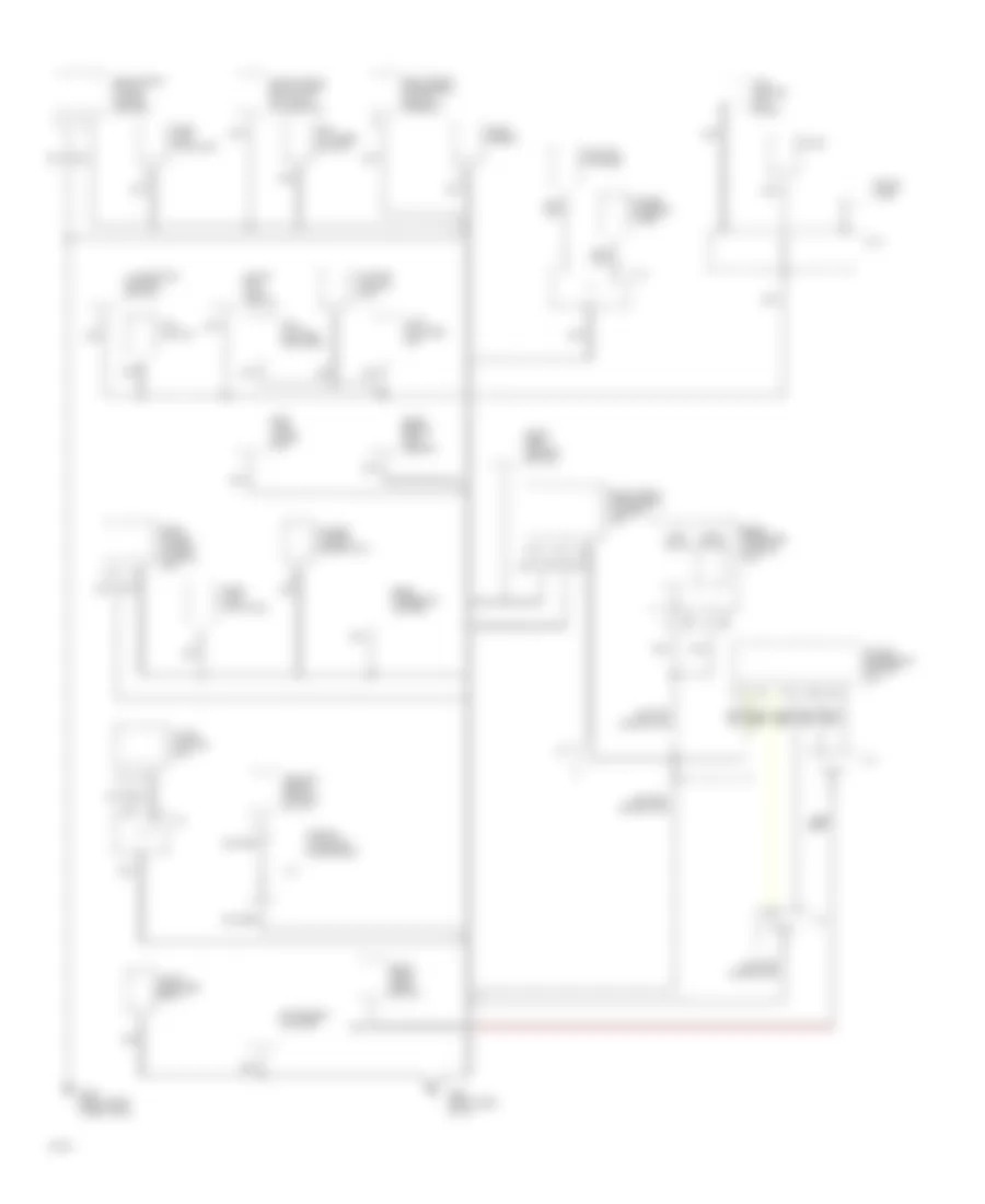
Automotive Electricians Portal FZCOList of elements for Traction Control Wiring Diagram (2 of 2) for Infiniti Q45 1994:
- (for
- (left front of engine)
- (left i/p)
- (left side of engine)
- (right front engine compt)
- All times
- Block (left kick
- Compt)
- Console)
- Consult) (left of steering column)
- Control module (behind center
- Data link connector
- Eccs
- Front engine
- Front of engine)
- Fuse
- Fuse & fusible link box (right side engine
- Fuse 10a
- Fuse 20a
- Fusible link g 30a
- G119 (right
- G201 (right side
- Hot at
- Hot in run
- Inhibitor switch (on transmission)
- J/c-3 (behind center of i/p)
- J/c-4
- J/c-5
- J/c-6
- J/c-7 (under left rear seat)
- J/c-8 (under
- Left rear seat)
- Motor
- N & p relay
- Nca
- Of i/p)
- Or start
- Panel)
- Red
- Secondary throttle position sensor
- Solenoid
- Tcm engine coolant temperature sensor (right side of engine)
- Tcs actuator
- Tcs pump (right
- Tcs pump relay (right
- Throttle
- Throttle control module (behind center console)
- Throttle motor relay
- Throttle position sensor (left front of engine)
- Valves
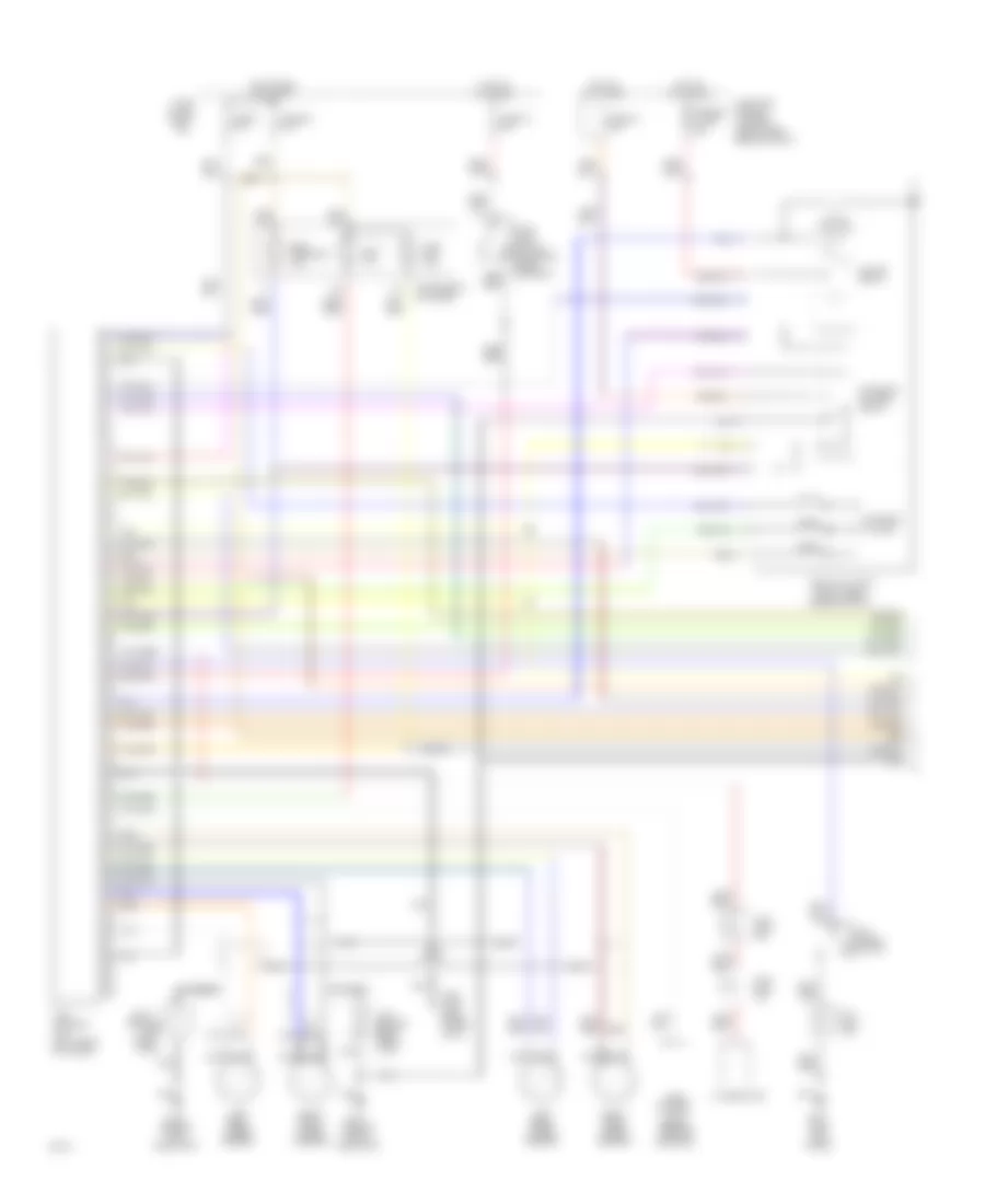
Traction Control Wiring Diagram (3 of 2) for Infiniti Q45 1994
 https://portal-diagnostov.com/license.html
Automotive Electricians Portal FZCO
Automotive Electricians Portal FZCO
https://portal-diagnostov.com/license.html
https://portal-diagnostov.com/license.html
Automotive Electricians Portal FZCO
Automotive Electricians Portal FZCOList of elements for Traction Control Wiring Diagram (3 of 2) for Infiniti Q45 1994:
- (behind
- (behind center
- (left i/p)
- (right rear
- Abs actuator
- Abs warning ind.
- All times
- Alternator
- Ascd
- Block (left
- Console)
- Control
- Engine compt)
- Fuse
- Fuse 1 10a
- Fuse 18 15a
- Fuse 25 10a
- Fuse 43 20a
- Fuse and fusible link box (right side engine compt)
- Fusible link b 30a
- G106
- G107
- G200 (left kick
- G402 (left rear wheel- well)
- Head- lamp)
- Headlamp)
- Hot at
- Hot in run or start
- I/p)
- Instrument cluster
- J/c-3 (behind right head- lamp)
- J/c-4
- J/c-4 (behind
- J/c-5 (left i/p)
- J/c-6 (left i/p)
- Left
- Left front wheel sensor
- Left rear wheel sensor
- Motor
- Motor relay
- Nca
- Panel)
- Right
- Right front wheel sensor
- Right rear wheel sensor
- Slip ind.
- Solenoid valves
- Solenoid valves relay
- Stop lamp switch (on brake pedal support)
- Tcs cancel switch
- Tcs control
- Tcs off ind.
- Unit
- Unit (left rear of trunk)
ANTI-THEFT
Anti-theft Wiring Diagram (1 of 2) for Infiniti Q45 1994
 https://portal-diagnostov.com/license.html
Automotive Electricians Portal FZCO
Automotive Electricians Portal FZCO
https://portal-diagnostov.com/license.html
https://portal-diagnostov.com/license.html
Automotive Electricians Portal FZCO
Automotive Electricians Portal FZCOList of elements for Anti-theft Wiring Diagram (1 of 2) for Infiniti Q45 1994:
- (behind
- (left center side of engine compt)
- (left kick panel)
- (right rear side
- (upper right side of i/p)
- B-20
- B-21
- Battery
- Body computer module (behind left side of i/p)
- Courtesy lamp relay
- Data lines
- Diodes
- Engine compt)
- Fuse & fusible link box (right side of
- Fuse 1 10a
- Fuse 31 15a
- Fuse 32 15a
- Fuse 38 10a
- Fuse 40 10a
- Fuse block (left i/p)
- Fuse link f 30a
- G106 (behind left headlamp)
- G107
- G200
- Head- lamps
- Headlamp relay unit
- Headlamp sensor (right front of engine compartment)
- Headlamp)
- Hood switch
- Hot at all times
- Hot in on or start
- Inhibitor switch (on
- Instrument cluster
- J/c-1 (right front of engine compt)
- J/c-5 (upper left side of i/p)
- J/c-6 (behind upper left side of i/p)
- J/c-8 (below left rear seat)
- Left front door switch
- Left rear door switch
- Multi-remote control unit
- Nca
- Of engine compt)
- Red
- Right
- Right front door switch
- Right rear door switch
- Security ind.
- Starter motor
- Starter relay
- Theft warning relay-1
- Theft warning relay-2 (right kick panel)
- Transmission)
Anti-theft Wiring Diagram (2 of 2) for Infiniti Q45 1994
 https://portal-diagnostov.com/license.html
Automotive Electricians Portal FZCO
Automotive Electricians Portal FZCO
https://portal-diagnostov.com/license.html
https://portal-diagnostov.com/license.html
Automotive Electricians Portal FZCO
Automotive Electricians Portal FZCOList of elements for Anti-theft Wiring Diagram (2 of 2) for Infiniti Q45 1994:
- (center rear of trunk lid)
- (inside left rear door)
- (inside right
- (inside right front door)
- (left kick panel)
- (right side of i/p)
- C 1995 vftc
- Control unit
- Control unit (inside left front door)
- Engine compt)
- Fuse & fusible link box (right side of
- Fuse 33 15a
- G200
- G201
- G404 (left rear side of trunk)
- High pitch horn
- Horn
- Horn relay
- Horn switch
- Hot at all times
- J/c-4 (right front wheelwell)
- Left front door lock actuator
- Left front power window
- Left key cylinder switch
- Left rear
- Left rear door lock actuator
- Lock
- Lock knob
- Lock-between full
- Lock-full stroke
- Low pitch horn
- Power window
- Rear door)
- Right front
- Right front door lock actuator
- Right key cylinder switch
- Right rear
- Right rear door lock actuator
- Stroke & neutral
- Switch
- Tamper-cylinder
- Theft
- Theft warning horn relay (left side of i/p)
- Trunk lid key cylinder switch
- Trunk room lamp
- Trunk room lamp switch
- Un- lock
- Unlock
- Unlock-between full
- Unlock-full stroke
- Warning
- Withdrawn
BODY COMPUTER
Body Computer Module Wiring Diagram for Infiniti Q45 1994
 https://portal-diagnostov.com/license.html
Automotive Electricians Portal FZCO
Automotive Electricians Portal FZCO
https://portal-diagnostov.com/license.html
https://portal-diagnostov.com/license.html
Automotive Electricians Portal FZCO
Automotive Electricians Portal FZCOList of elements for Body Computer Module Wiring Diagram for Infiniti Q45 1994:
- (for consult)
- (left kick panel)
- (left side
- (right
- Adp steering switch
- Body computer
- C 1995 vftc
- Circuit breaker-1 (left side of i/p)
- Data line a
- Data line b
- Data link connector
- Detention switch
- Door switches
- Engine compt)
- Fuse & fusible
- Fuse 10 10a
- Fuse 19 10a
- Fuse 20 10a
- Fuse 25 10a
- Fuse 40 10a
- Fuse block (left i/p)
- G200
- Headlamp relay unit
- Hood switch
- Hot at all times
- Hot in on
- Hot in on or start
- Hot in start
- Illumination control switch
- Inhibitor switch (reverse input)
- Instrument cluster (security indicator)
- Instrument cluster (speedometer)
- Instrument cluster (warning chime)
- Interior lamp
- Intermittent wiper volume
- J/c-4 (behind instrument cluster)
- J/c-8 (left rear door sill)
- Key
- Key switch
- Left door mirror control unit (in mirror assembly)
- Left front power seat control unit (under left front seat)
- Left front power seat switch assembly
- Left front power window control unit (in left front door)
- Left rear power window control unit (in left rear door)
- Lh & rh door mirror control units (defogger)
- Link box
- Main power window switch (left rear down)
- Main power window switch (left rear up)
- Main power window switch (lock)
- Main power window switch (right front down)
- Main power window switch (right front up)
- Main power window switch (right rear down)
- Main power window switch (right rear up)
- Mirror switch (down)
- Mirror switch (left change-over)
- Mirror switch (left)
- Mirror switch (right change-over)
- Mirror switch (right)
- Mirror switch (up)
- Module (behind left side of i/p)
- Multi-remote control unit (upper left rear of trunk)
- Nca
- Of i/p)
- Or acc
- Pnk
- Rear window defogger relay
- Rear window defogger switch
- Red
- Right door mirror control unit (in mirror assembly)
- Right front power seat control unit (under right front seat)
- Right front power seat switch assembly
- Right front power window control unit (in right front door)
- Right rear power window control unit (in right rear door)
- Shift
- Shift lock control unit
- Side
- Telescopic motor
- Theft warning relay-1 & theft horn relay
- Theft warning relay-2
- Tilt & telescopic sensors
- Tilt motor
- Trunk lid key cylinder switch
- Trunk room lamp switch
- Wiper amplifier
- Wiper amplifier, wiper switch
- Wiper switch, washer motor
COMPUTER DATA LINES
Data Link Connector Wiring Diagram for Infiniti Q45 1994
 https://portal-diagnostov.com/license.html
Automotive Electricians Portal FZCO
Automotive Electricians Portal FZCO
https://portal-diagnostov.com/license.html
https://portal-diagnostov.com/license.html
Automotive Electricians Portal FZCO
Automotive Electricians Portal FZCOList of elements for Data Link Connector Wiring Diagram for Infiniti Q45 1994:
- (behind left
- (left of steering column)
- (left side
- (lower right
- (upper center rear of trunk)
- 1994 vftc c
- A/t control unit (left kick panel)
- Active suspension control unit
- Ascd control unit (behind center console)
- Body control module (left side of i/p)
- Data link connector (for consult)
- Diagnostic information display control unit
- Eccs control module (behind center console)
- Fuse 10a
- Fuse block (left kick panel)
- G106
- G200 (left kick panel)
- Headlamp)
- Hicas
- Hicas control unit
- Hicas control unit (upper center rear of trunk)
- Hot in run or start
- Instrument cluster
- J/c-1 (behind center of i/p)
- J/c-2 (behind center of i/p)
- J/c-3
- Of i/p)
- Power steering
- Power steering control unit (behind center console)
- Side of engine)
- Solenoid
- Speedo- meter
- Srs diagnosis (control) unit (left side of i/p)
- Throttle control module (behind center console)
- W/ hicas
- W/o
- W/o hicas
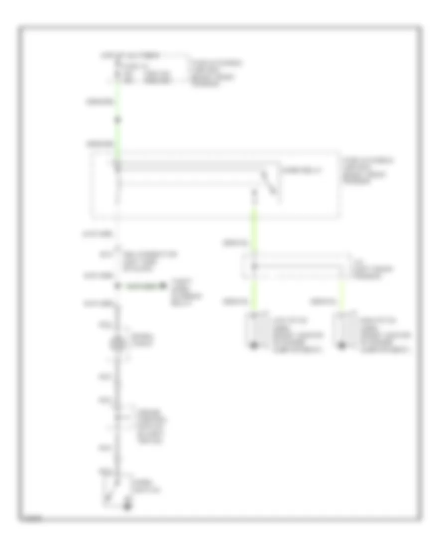
COOLING FAN
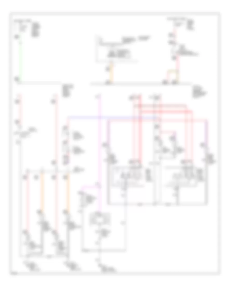
Cooling Fan Wiring Diagram, Canada for Infiniti Q45 1994
 https://portal-diagnostov.com/license.html
Automotive Electricians Portal FZCO
Automotive Electricians Portal FZCO
https://portal-diagnostov.com/license.html
https://portal-diagnostov.com/license.html
Automotive Electricians Portal FZCO
Automotive Electricians Portal FZCOList of elements for Cooling Fan Wiring Diagram, Canada for Infiniti Q45 1994:
- A/c pressure switch (center front engine compt)
- Cooling fan motor
- Cooling fan relay
- Eccs control module (behind center console)
- Fuse & fusible link box (right side engine compt)
- Fuse 10a
- Fuse block (right kick panel)
- Fusible link j 30a
- G100 (left front fender)
- G101 (right front fender)
- Hot at all times
- Hot in run
- J/c-1 (right front engine compt)
- Nca
- Or start
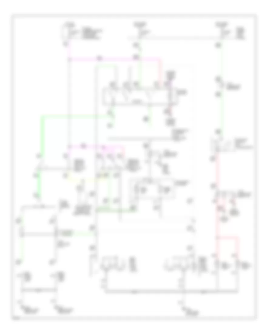
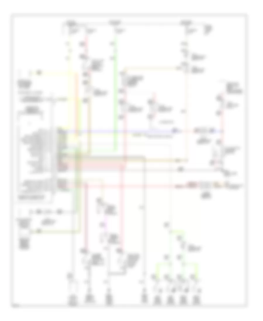
Cooling Fan Wiring Diagram, USA for Infiniti Q45 1994
 https://portal-diagnostov.com/license.html
Automotive Electricians Portal FZCO
Automotive Electricians Portal FZCO
https://portal-diagnostov.com/license.html
https://portal-diagnostov.com/license.html
Automotive Electricians Portal FZCO
Automotive Electricians Portal FZCOList of elements for Cooling Fan Wiring Diagram, USA for Infiniti Q45 1994:
- A/c pressure switch (center front engine compt)
- Cooling fan motor
- Cooling fan relay no.1
- Cooling fan relay no.2
- Eccs control module (behind center console)
- Fuse & fusible link box (right side engine compt)
- Fuse 10a
- Fuse block (right kick panel)
- Fusible link j 30a
- G100 (left front fender)
- G101 (right front fender)
- Hot at all times
- Hot in run
- J/c-1 (right front engine compt)
- J/c-6 (left side of i/p)
- Nca
- Or start
CRUISE CONTROL
Cruise Control Wiring Diagram for Infiniti Q45 1994
 https://portal-diagnostov.com/license.html
Automotive Electricians Portal FZCO
Automotive Electricians Portal FZCO
https://portal-diagnostov.com/license.html
https://portal-diagnostov.com/license.html
Automotive Electricians Portal FZCO
Automotive Electricians Portal FZCOList of elements for Cruise Control Wiring Diagram for Infiniti Q45 1994:
- (below left rear seat)
- (right front fender)
- 1995 vftc c
- A/t control unit (below left rear shelf)
- Act. cntrl
- Actuator control
- Air valve solenoid
- Ascd actuator (left rear of engine compartment)
- Ascd brake switch (top of brake pedal support)
- Ascd control unit (left side of i/p)
- Ascd hold relay (relay box, right front fender)
- Ascd steering switch
- Ascd sw.
- Ascd switch (left side of i/p)
- B12
- Cancel
- Crs. cancl
- Cruise
- Cruise indicator
- Cruise signal
- Data link
- Data link connector for consult (lower left side of i/p)
- Fuse & fusible link box (right front fender)
- Fuse 18 15a
- Fuse 2 10a
- Fuse 26 10a
- Fuse 33 15a
- Fuse block (left side of i/p)
- G101
- G200 (left kick panel)
- Ground
- Horn relay (relay box, right front fender)
- Horns
- Hot at all times
- Hot in on or start
- Illum.
- Inhibitor switch (right side of transmission)
- Instrument cluster
- Interior lights system
- Interior lights system (rheostat)
- J/c 2 (right side of i/p)
- J/c 3 (left side of i/p)
- J/c 4 (left side of i/p)
- J/c 6 (left side of i/p)
- J/c 7
- Nca
- Neutral & park relay (relay box, right front fender)
- Od cut signal
- On ind.
- Pnk
- Release valve solenoid
- Resume/ accelerate
- Set/coast
- Smj
- Smj connector
- Smj connector (left kick panel)
- Speed
- Spiral cable
- Steering switch
- Stop lamp switch (top of brake pedal support)
- Stop lamp switch od cut
- Tcs control unit (left side of i/p)
- Tcs unit
- Vacuum motor
- Vehicle speed output
DEFOGGERS
Defogger Wiring Diagram for Infiniti Q45 1994
 https://portal-diagnostov.com/license.html
Automotive Electricians Portal FZCO
Automotive Electricians Portal FZCO
https://portal-diagnostov.com/license.html
https://portal-diagnostov.com/license.html
Automotive Electricians Portal FZCO
Automotive Electricians Portal FZCOList of elements for Defogger Wiring Diagram for Infiniti Q45 1994:
- Body control module (left side of i/p)
- Condenser (left "c" pillar)
- Data a
- Data b
- Defog rly
- Defog sw
- Door mirror
- Door mirror control unit
- Fuse 10a
- Fuse 20a
- Fuse block (left side of i/p)
- G200 (left kick panel)
- Hot at all times
- Hot in acc or run
- Hot in run or start
- Illum.
- Interior lights system
- J/c 1 (right side of i/p)
- J/c 4 (left side of i/p)
- J/c 5 (left side of i/p)
- Left side
- Nca
- On ind.
- Rear window defogger
- Rear window defogger relay (left side of i/p)
- Rear window defogger switch
- Right side
ELECTRONIC POWER STEERING
Electronic Power Steering Wiring Diagram, with Hicas System for Infiniti Q45 1994
 https://portal-diagnostov.com/license.html
Automotive Electricians Portal FZCO
Automotive Electricians Portal FZCO
https://portal-diagnostov.com/license.html
https://portal-diagnostov.com/license.html
Automotive Electricians Portal FZCO
Automotive Electricians Portal FZCOList of elements for Electronic Power Steering Wiring Diagram, with Hicas System for Infiniti Q45 1994:
- (behind left
- (left front
- (left rear
- (left rear wheelwell)
- (lower right
- (right side
- (under left
- (upper center rear of trunk)
- 1994 vftc c
- All times
- Block (left kick
- Column)
- Data link connector (for consult) (left of steering column)
- Eccs control module (behind center console)
- Engine compt)
- Fail-safe valve (left rear wheelwell)
- Full active suspension control unit
- Fuse
- Fuse & fusible
- Fuse 10a
- Fuse 15a
- G106
- G200 (left kick panel)
- G201 (right side of i/p)
- G404
- Headlamp)
- Hicas control unit
- Hicas ind.
- Hicas solenoid
- Hot at
- Hot in run
- Inhibitor
- Instrument cluster
- J/c
- J/c-1 (behind center of i/p)
- J/c-2 (behind center of i/p)
- J/c-3 (behind center of i/p)
- J/c-4 (behind center of i/p)
- J/c-5 (behind left side of i/p)
- J/c-7
- J/c-7 (under left rear seat)
- Link box
- N & p relay
- Nca
- Or start
- Panel)
- Park brake switch
- Power steering
- Power steering oil level switch
- Rear seat)
- Red
- Shock tower)
- Side of engine)
- Side of trunk)
- Solenoid
- Speed sensor (on transmission)
- Speedometer
- Steering angle sensor (bottom of steering
- Stop lamp switch
- Switch
Electronic Power Steering Wiring Diagram, with Twin Orifice System for Infiniti Q45 1994
 https://portal-diagnostov.com/license.html
Automotive Electricians Portal FZCO
Automotive Electricians Portal FZCO
https://portal-diagnostov.com/license.html
https://portal-diagnostov.com/license.html
Automotive Electricians Portal FZCO
Automotive Electricians Portal FZCOList of elements for Electronic Power Steering Wiring Diagram, with Twin Orifice System for Infiniti Q45 1994:
- (lower right
- 1994 vftc c
- All times
- Data link connector (for consult) (left of steering column)
- Fuse & fusible link box (right side engine compt)
- Fuse 10a
- Fuse 15a
- Fuse block (left kick panel)
- G106 (behind left headlamp)
- G200 (left kick panel)
- G201 (right side of i/p)
- Hot at
- Hot in run
- Inhibitor switch
- Instrument cluster
- J/c-1 (behind center of i/p)
- J/c-2 (behind center of i/p)
- J/c-5 (behind left side of i/p)
- J/c-6 (behind left side of i/p)
- J/c-7 (under left rear seat)
- N & p relay
- Nca
- Or start
- Park brake
- Power steering
- Power steering control unit (behind center console)
- Side of engine)
- Solenoid
- Speed sensor (on transmission)
- Speedometer
- Stop lamp switch
- Switch
ELECTRONIC SUSPENSION
Electronic Suspension Wiring Diagram (1 of 2) for Infiniti Q45 1994
 https://portal-diagnostov.com/license.html
Automotive Electricians Portal FZCO
Automotive Electricians Portal FZCO
https://portal-diagnostov.com/license.html
https://portal-diagnostov.com/license.html
Automotive Electricians Portal FZCO
Automotive Electricians Portal FZCOList of elements for Electronic Suspension Wiring Diagram (1 of 2) for Infiniti Q45 1994:
- "c"
- (behind lh headlamp)
- (behind rh headlamp)
- (bottom left
- (left front wheelwell)
- (right rear wheelwell)
- Control unit (bottom front
- Data link connector (for consult) (left of steering column)
- Door switches (diagnostic information display)
- Engine ground
- Fail- safe valve
- Flow control valve
- Front of engine)
- Front pressure
- Full-active suspension control unit (top center rear of trunk)
- Fuse 18 15a
- Fuse 23 15a
- Fuse 27 15a
- Fuse block (left i/p)
- G106
- G107
- G403
- Hot at all times
- Hot in run or start
- Ill.
- Interior lights system
- J/c (bottom of left
- J/c-3 (left side of i/p)
- Left front pressure control valve
- Left rear pressure control valve
- Multi-valve unit
- N & p relay (electronic power steering system)
- Oil level switch (forward of left front wheelwell)
- Oil pressure switch (lower front of engine)
- Pillar)
- Pump solenoids
- Rear of vehicle)
- Rear pressure control unit (bottom left
- Red
- Right front pressure control valve
- Right of vehicle)
- Right rear pressure control valve
- Stop lamp switch (on brake pedal support)
- Vehicle height control switch
Electronic Suspension Wiring Diagram (2 of 2) for Infiniti Q45 1994
 https://portal-diagnostov.com/license.html
Automotive Electricians Portal FZCO
Automotive Electricians Portal FZCO
https://portal-diagnostov.com/license.html
https://portal-diagnostov.com/license.html
Automotive Electricians Portal FZCO
Automotive Electricians Portal FZCOList of elements for Electronic Suspension Wiring Diagram (2 of 2) for Infiniti Q45 1994:
- (center of engine compt)
- (forward of
- (forward of left front shock tower)
- (in console)
- (left front
- (left kick
- (left rear wheelwell)
- (left side of i/p)
- (on
- (right
- (right front
- (right rear wheelwell)
- (top center
- A/t
- Act sus ind.
- Brake ind.
- Console)
- Control
- Control module (behind center
- Control unit
- Diode
- Eccs
- Electronic
- Fore & aft g sensor
- Front lateral g sensor-1
- Front vertical g sensor
- Full-active suspension
- Fuse 25 10a
- Fuse block (left i/p)
- G201
- G403
- Height ind.
- Height sensor
- Hot in run or start
- I/p)
- Instrument cluster
- J/c-1 (behind center i/p)
- Left front
- Left rear vehicle height sensor
- Left rear vertical g sensor
- Nca
- Oil
- Oil cooler fan motor (left front shock tower)
- Oil cooler fan relay (left rear engine compt)
- Panel)
- Parking brake switch (left i/p)
- Pnk
- Rear lateral g sensor-2
- Rear of trunk)
- Right front
- Right rear vehicle height sensor
- Right rear vertical g sensor
- Sensor
- Shock tower)
- Speed sensor
- Speedometer
- Temperature
- Transmission)
- Unit
- Vehicle
- Wheelwell)
ENGINE PERFORMANCE
4.5L
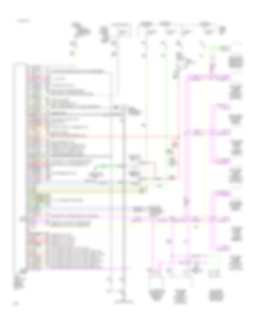
4.5L, Engine Performance Wiring Diagrams (1 of 2) for Infiniti Q45 1994
 https://portal-diagnostov.com/license.html
Automotive Electricians Portal FZCO
Automotive Electricians Portal FZCO
https://portal-diagnostov.com/license.html
https://portal-diagnostov.com/license.html
Automotive Electricians Portal FZCO
Automotive Electricians Portal FZCOList of elements for 4.5L, Engine Performance Wiring Diagrams (1 of 2) for Infiniti Q45 1994:
- (attached to top cylinder block)
- (top front of eng)
- 10a
- 25a
- Acc
- Cam- shaft position sensor (left front of eng)
- Canister control solenoid valve (left front of eng)
- Check connector
- Cooling fans system
- Data link connector (under left side of i/p)
- Ecm relay (in left kick panel)
- Egrc solenoid valve (left front of eng)
- Engine control module (in right kick panel)
- Engine temperature sensor (left rear of eng)
- Fuse
- Fuse box (i/p)
- Fusible link & fuse box (underhood)
- G110 (left front of eng)
- G200 (left kick panel)
- Hot at all times
- Hot in start or on
- Iacv-aac valve (top rear of eng)
- Ignition switch
- Instrument cluster system (tach)
- J/c f
- Left heated oxygen sensor (on left exhaust manifold)
- Left knock sensor
- Left power transistor unit (top left of eng)
- Mass air flow sensor (left front of eng)
- Nca
- Off
- Power steering/ oil pressure switch
- Red
- Right heated oxygen sensor (on right exhaust manifold)
- Right knock sensor
- Smj
- Start
- Sub- camshaft position sensor (left front of eng)
- Vtc solenoid valve (left)
- Vtc solenoid valve (right)
- W/ tcs only
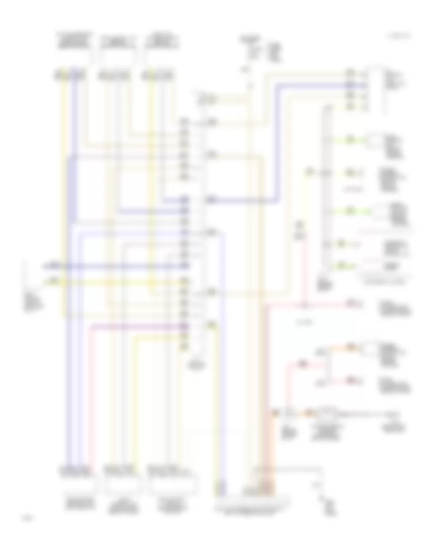
4.5L, Engine Performance Wiring Diagrams (2 of 2) for Infiniti Q45 1994
 https://portal-diagnostov.com/license.html
Automotive Electricians Portal FZCO
Automotive Electricians Portal FZCO
https://portal-diagnostov.com/license.html
https://portal-diagnostov.com/license.html
Automotive Electricians Portal FZCO
Automotive Electricians Portal FZCOList of elements for 4.5L, Engine Performance Wiring Diagrams (2 of 2) for Infiniti Q45 1994:
- (left rear of eng)
- 15a
- 25a
- 30a
- A/t control unit (above left kick panel)
- Acc
- Check connector
- Egr temperature sensor (left rear of eng)
- Engine control module (in right kick panel)
- F11
- Fuel pump (in fuel tank)
- Fuel pump control module (under center of rear shelf)
- Fuel pump relay (left side of trunk)
- Fuel red
- Fuse
- Fuse box (i/p)
- Fusible link & fuse box (under hood)
- Fusible link & fuse box (underhood)
- G114
- G117 (right rear of eng)
- Hot at all times
- Hot in start or on
- Ignition coil #1
- Ignition coil #2
- Ignition coil #3
- Ignition coil #4
- Ignition coil #5
- Ignition coil #6
- Ignition coil #7
- Ignition coil #8
- Ignition coil relay (in right kick panel)
- Ignition switch
- Injectors
- Instrument cluster
- J/b g
- J/c f
- J/c g
- J/c h
- Mal- function indicator lamp
- Nca
- No.1
- No.2
- No.3
- No.4
- No.5
- No.6
- No.7
- No.8
- Off
- Park/neutral position relay
- Red
- Resistor
- Right power transistor unit (top right of eng)
- Secondary throttle position sensor (w/ tcs) (left front of eng)
- Smj
- Start
- Throttle control module (w/ tcs) (center of i/p)
- Throttle position sensor/switch (on throttle body)
- W/ tcs only
EXTERIOR LIGHTS
Exterior Light Wiring Diagram (1 of 2) for Infiniti Q45 1994
 https://portal-diagnostov.com/license.html
Automotive Electricians Portal FZCO
Automotive Electricians Portal FZCO
https://portal-diagnostov.com/license.html
https://portal-diagnostov.com/license.html
Automotive Electricians Portal FZCO
Automotive Electricians Portal FZCOList of elements for Exterior Light Wiring Diagram (1 of 2) for Infiniti Q45 1994:
- (behind left headlamp)
- (behind right headlamp)
- (brake pedal support bracket)
- (right rear side of trunk)
- Diagnostic information display
- Diagnostic information display control unit
- Fuse & fusible link box (right side of engine compt)
- Fuse 10a
- Fuse 18 15a
- Fuse block (left kick panel)
- G106
- G107
- G404
- Head
- Headlamp relay unit (right side of engine compt)
- High- mounted stop lamp-1
- High- mounted stop lamp-2
- Hot at all times
- Instrument cluster
- J/c-2 (upper right side of i/p)
- J/c-5 (left side of i/p)
- J/c-6 (upper left side of i/p)
- Left front clearance light
- Left front side marker light
- Left license light
- Left rear side marker light
- Left rear tail/ stop/ turn lights
- Light switch
- Nca
- Off
- Park
- Rear lamps sensor
- Red
- Right front clearance light
- Right front side marker light
- Right license light
- Right rear side marker light
- Right rear tail/ stop/ turn lights
- Stop & tail lamp sensor (center rear of luggage compt)
- Stop lamp switch
Exterior Light Wiring Diagram (2 of 2) for Infiniti Q45 1994
 https://portal-diagnostov.com/license.html
Automotive Electricians Portal FZCO
Automotive Electricians Portal FZCO
https://portal-diagnostov.com/license.html
https://portal-diagnostov.com/license.html
Automotive Electricians Portal FZCO
Automotive Electricians Portal FZCOList of elements for Exterior Light Wiring Diagram (2 of 2) for Infiniti Q45 1994:
- (left rear of trunk)
- (left side of i/p)
- (under left rear seat)
- (upper left
- (upper left side of i/p)
- A-12
- A-6
- A-9
- A/t control unit
- Body control module
- Combination flasher unit (left side of i/p)
- Fuse & fusible link box (right side of engine compartment)
- Fuse 2 10a
- Fuse 24 10a
- Fuse 34 10a
- Fuse block (left kick panel)
- G106 (behind left headlamp)
- G107 (behind right headlamp)
- G200 (left kick panel)
- G404
- Hazard
- Hazard switch
- Hot at all times
- Hot in run or start
- Ill.
- Inhibitor switch (on transmission)
- Instrument cluster
- Interior lights system
- J/c-5
- J/c-7
- Left back-up light
- Left front turn light
- Left rear tail/ stop/ turn lights
- Left turn ind.
- Multi-remote control unit
- Nca
- Rear of trunk)
- Red
- Remote control relay-1 (left kick panel)
- Remote control relay-2 (left kick panel)
- Right back-up light
- Right front turn light
- Right rear tail/ stop/ turn lights
- Right turn ind.
- Turn signal switch
GROUND DISTRIBUTION
Ground Distribution Wiring Diagram (1 of 6) for Infiniti Q45 1994
 https://portal-diagnostov.com/license.html
Automotive Electricians Portal FZCO
Automotive Electricians Portal FZCO
https://portal-diagnostov.com/license.html
https://portal-diagnostov.com/license.html
Automotive Electricians Portal FZCO
Automotive Electricians Portal FZCOList of elements for Ground Distribution Wiring Diagram (1 of 6) for Infiniti Q45 1994:
- Active suspension control unit
- Active suspension pump
- Camshaft position sensor
- Camshaft position sensor shield
- Check connector
- Ecm (eccs control module)
- G114 (left rear of engine)
- G117 (right rear of engine)
- G119 (right front of engine)
- Ignition coil n0. 7
- Ignition coil no. 1
- Ignition coil no. 2
- Ignition coil no. 3
- Ignition coil no. 4
- Ignition coil no. 5
- Ignition coil no. 6
- Ignition coil no. 8
- Left heated oxygen sensor shield
- Left knock sensor shield
- Left power transistor unit
- Mass air flow sensor shield
- Models w/ tcs
- Nca
- Right heated oxygen sensor shield
- Right knock sensor shield
- Right power transistor unit
- Secondary throttle position sensor shield
- Sub- camshaft position sensor
- Sub- camshaft position sensor shield
- Throttle control module
- Throttle position sensor shield
Ground Distribution Wiring Diagram (2 of 6) for Infiniti Q45 1994
 https://portal-diagnostov.com/license.html
Automotive Electricians Portal FZCO
Automotive Electricians Portal FZCO
https://portal-diagnostov.com/license.html
https://portal-diagnostov.com/license.html
Automotive Electricians Portal FZCO
Automotive Electricians Portal FZCOList of elements for Ground Distribution Wiring Diagram (2 of 6) for Infiniti Q45 1994:
- A/c pressure switch
- Abs actuator
- Ascd hold relay
- Brake fluid level switch
- Combination switch
- Cooling fan motor
- Daytime light control unit
- Eps
- Front pressure control unit
- Full active suspension control
- G101 (right front fender)
- G107 (behind right front headlamp)
- Headlamp relay unit
- Headlamp sensor
- Hicas solenoid
- Hood switch
- J/c-3
- J/c-4
- Lamp
- Left front combination lamp
- Left front fog lamp
- Left front side marker lamp
- Left front wheel sensor shield
- Marker lamp
- Models w/ active suspension
- Multi valve unit
- Nca
- Neutral and park relay
- Oil cooler fan motor
- Oil level switch
- Oil pressure switch
- Power steering oil level switch
- Right front combination
- Right front fog
- Right front side
- Right front wheel sensor
- Shield
- Solenoid
- Starter relay
- Tcs actuator
- Tcs body ground
- Tcs loading pump
- Thermo- switch
- Unit
- Washer sensor
- Wiper amplifier
- Wiper motor
Ground Distribution Wiring Diagram (3 of 6) for Infiniti Q45 1994
 https://portal-diagnostov.com/license.html
Automotive Electricians Portal FZCO
Automotive Electricians Portal FZCO
https://portal-diagnostov.com/license.html
https://portal-diagnostov.com/license.html
Automotive Electricians Portal FZCO
Automotive Electricians Portal FZCOList of elements for Ground Distribution Wiring Diagram (3 of 6) for Infiniti Q45 1994:
- Accessory relay-1
- Accessory relay-2
- Ascd control unit
- Ascd switch
- Ashtray illumination
- Auto drive positioner steering switch
- Body control module
- Cigarette lighter
- Combination flasher unit
- Courtesy lamp relay
- Data link connector (for consult)
- Diagnostic information display control unit
- Door handle switch and key hole illumination
- Door lock actuator
- Door mirror
- Door mirror switch
- Fuse block
- G200 (left side kick panel)
- Ignition relay-1
- Ignition relay-2
- Instrument cluster module
- Interior lamp
- J/c
- J/c-4
- Key cylinder switch
- Kickdown switch
- Left front power seat switch assembly
- Left front power window control unit
- Mode door motor
- Pnk
- Power steering control unit
- Rear window defogger switch
- Red
- Room mirror
- Shift lock control unit
- Spot lamp
- Steering angle sensor
- Sun roof relay
- Tcs switch
- Theft warning horn relay
- To fail- safe valve
- Trunk lid and fuel lid opener switch
- Vanity mirror illumination
- Wiper switch
Ground Distribution Wiring Diagram (4 of 6) for Infiniti Q45 1994
 https://portal-diagnostov.com/license.html
Automotive Electricians Portal FZCO
Automotive Electricians Portal FZCO
https://portal-diagnostov.com/license.html
https://portal-diagnostov.com/license.html
Automotive Electricians Portal FZCO
Automotive Electricians Portal FZCOList of elements for Ground Distribution Wiring Diagram (4 of 6) for Infiniti Q45 1994:
- A/c switch
- Active suspension control unit
- Audio amplifier relay
- Auto amplifier (a/c)
- B52
- B53
- Blower hi relay (a/c)
- Cd auto changer
- Clock
- Door handle switch and key hole illumination
- Door lock actuator
- Door mirror
- Fan control amplifier
- Fuel tank gauge unit
- G201 (right side of i/p)
- G403 (right rear wheel well)
- Glove box lamp switch
- Hicas control unit
- Illumination control switch
- Instrument cluster
- J/c
- J/c-4
- Key cylinder switch
- Left valve
- Models w/ active suspension
- Power antenna timer
- Power window sub-switch
- Rear brake pad sensor
- Rear cigarette lighter
- Rear power window control unit
- Rear pressure control unit
- Right front door switch
- Right front power seat control unit
- Right front power seat switch assembly
- Right front power window control
- Right seat heater switch
- Right valve
- Shield wire
- Tcs control unit shield
- Vehicle height control switch
Ground Distribution Wiring Diagram (5 of 6) for Infiniti Q45 1994
 https://portal-diagnostov.com/license.html
Automotive Electricians Portal FZCO
Automotive Electricians Portal FZCO
https://portal-diagnostov.com/license.html
https://portal-diagnostov.com/license.html
Automotive Electricians Portal FZCO
Automotive Electricians Portal FZCOList of elements for Ground Distribution Wiring Diagram (5 of 6) for Infiniti Q45 1994:
- Abs control unit
- Body ground shield
- Fore and aft g sensor shield
- Front vertical g sensor
- G201 (right side of i/p)
- G400 (left front side of trunk)
- G401 (right front side of trunk)
- Instrument cluster
- Lateral g sensor-1 shield
- Lateral g sensor-2 shield
- Left door speaker
- Left rear speaker
- Left rear vertical g sensor shield
- Nca
- Rear skid sensor shield
- Right door speaker
- Right rear speaker
- Right rear vertical g sensor shield
- Right tweeter shield
- Room lamp harness shield
- Shield
- Tcs control unit
Ground Distribution Wiring Diagram (6 of 6) for Infiniti Q45 1994
 https://portal-diagnostov.com/license.html
Automotive Electricians Portal FZCO
Automotive Electricians Portal FZCO
https://portal-diagnostov.com/license.html
https://portal-diagnostov.com/license.html
Automotive Electricians Portal FZCO
Automotive Electricians Portal FZCOList of elements for Ground Distribution Wiring Diagram (6 of 6) for Infiniti Q45 1994:
- Door lock actuator
- Fail- safe valve
- From g200
- G400 (left side of trunk)
- Handset and speaker
- High- mounted stop lamp
- High-mounted stop lamp
- Left front door switch
- Left front power seat control unit
- Left license lamp
- Left power window console switch
- Left rear combination lamp
- Left rear power window control unit
- Left rear side marker lamp
- Left seat heater switch
- Left side back-up lamp
- Models w/ rear air spoiler
- Models w/ teleph0ne
- Multi- remote control unit
- Power window sub- switch
- Rear cigarette lighter
- Receiver
- Right license lamp
- Right rear combination lamp
- Right rear side marker lamp
- Right side back-up lamp
- Shift lock solenoid and detention switch
- Steering receiver
- Stop and tail lamp sensor
- Switch
- Trunk lid unlock switch
- Trunk room lamp
HEADLIGHTS
DRL Wiring Diagram (1 of 2) for Infiniti Q45 1994
 https://portal-diagnostov.com/license.html
Automotive Electricians Portal FZCO
Automotive Electricians Portal FZCO
https://portal-diagnostov.com/license.html
https://portal-diagnostov.com/license.html
Automotive Electricians Portal FZCO
Automotive Electricians Portal FZCOList of elements for DRL Wiring Diagram (1 of 2) for Infiniti Q45 1994:
- (behind left side of i/p)
- (behind right headlamp)
- (left
- (left side of i/p)
- (right front
- Body computer module
- Compartment)
- Diagnostic information display
- Diagnostic information display control unit
- Diode
- Diode (left side of i/p)
- Engine compt)
- Fuse & fusible link box (right side engine compt)
- Fuse & fusible link box (right side of
- Fuse 10a
- Fuse 31 15a
- Fuse 32 15a
- G106 (behind left headlamp)
- G107 (behind right headlamp)
- G200 (left kick panel)
- Headlamp
- Headlamp relay unit
- Headlamp sensor
- Headlamps on
- Hi beam ind.
- Hot at all times
- I/p)
- Instrument cluster
- J/c-1 (right front of engine compt)
- J/c-2
- J/c-5
- J/c-6 (left
- Left dual beam head- lamp
- Left hi beam head- lamp
- Light switch
- Of engine
- Off
- Park head lo beam hi beam flash- to-pass
- Red
- Right dual beam head-
- Right hi beam head- lamp
- Sensor
- Theft warning relay-1
DRL Wiring Diagram (2 of 2) for Infiniti Q45 1994
 https://portal-diagnostov.com/license.html
Automotive Electricians Portal FZCO
Automotive Electricians Portal FZCO
https://portal-diagnostov.com/license.html
https://portal-diagnostov.com/license.html
Automotive Electricians Portal FZCO
Automotive Electricians Portal FZCOList of elements for DRL Wiring Diagram (2 of 2) for Infiniti Q45 1994:
- (left front engine compt)
- (left i/p)
- (right front engine compt)
- Alternator
- Daytime light cancel relay
- Daytime light control unit (below right
- Diode (left i/p)
- Fuse & fusible link box (right side engine compt)
- Fuse 13 10a
- Fuse 40 10a
- Fuse block (left kick panel)
- Headlamp)
- Hot in on or start
- Hot in start
- I/p)
- J/c-1
- J/c-1 (right
- J/c-6 (left
- J/c-6 (right
- Parking brake switch
- Red
Fog Lamps Wiring Diagram for Infiniti Q45 1994
 https://portal-diagnostov.com/license.html
Automotive Electricians Portal FZCO
Automotive Electricians Portal FZCO
https://portal-diagnostov.com/license.html
https://portal-diagnostov.com/license.html
Automotive Electricians Portal FZCO
Automotive Electricians Portal FZCOList of elements for Fog Lamps Wiring Diagram for Infiniti Q45 1994:
- (behind right
- (left
- (right front
- Canada
- Compartment)
- Daytime light control unit (below right headlamp)
- Fog light relay (left kick panel)
- Fog light switch (combination switch)
- Fuse & fusible link box (right side engine compt)
- Fuse 32 15a
- Fuse 37 10a
- Fuse 39 15a
- G106 (behind left headlamp)
- G107 (behind right headlamp)
- Headlamp relay unit
- Headlamp)
- Hot at all times
- I/p)
- J/c-2
- J/c-5
- J/c-6 (left i/p)
- Left fog light
- Light switch
- Of engine
- Off
- Park head lo beam hi beam flash- to-pass
- Right fog light
- Usa
Headlamps Wiring Diagram for Infiniti Q45 1994
 https://portal-diagnostov.com/license.html
Automotive Electricians Portal FZCO
Automotive Electricians Portal FZCO
https://portal-diagnostov.com/license.html
https://portal-diagnostov.com/license.html
Automotive Electricians Portal FZCO
Automotive Electricians Portal FZCOList of elements for Headlamps Wiring Diagram for Infiniti Q45 1994:
- (behind left side of i/p)
- (behind right headlamp)
- (left
- (left side of i/p)
- (right front
- Body computer module
- Compartment)
- Diagnostic information display
- Diagnostic information display control unit
- Diode
- Diode (left side of i/p)
- Engine compt)
- Fuse & fusible link box (right side engine compt)
- Fuse & fusible link box (right side of
- Fuse 10a
- Fuse 31 15a
- Fuse 32 15a
- G106 (behind left headlamp)
- G107 (behind right headlamp)
- G200 (left kick panel)
- Headlamp
- Headlamp relay unit
- Headlamp sensor
- Headlamps on
- Hi beam ind.
- Hot at all times
- I/p)
- Instrument cluster
- J/c-1 (right front of engine compt)
- J/c-2
- J/c-5
- J/c-6 (left i/p)
- Left dual beam head- lamp
- Left hi beam head- lamp
- Light switch
- Of engine
- Off
- Park head lo beam hi beam flash- to-pass
- Red
- Right dual beam head-
- Right hi beam head- lamp
- Sensor
- Theft warning relay-1
HORN
Horn Wiring Diagram for Infiniti Q45 1994
 https://portal-diagnostov.com/license.html
Automotive Electricians Portal FZCO
Automotive Electricians Portal FZCO
https://portal-diagnostov.com/license.html
https://portal-diagnostov.com/license.html
Automotive Electricians Portal FZCO
Automotive Electricians Portal FZCOList of elements for Horn Wiring Diagram for Infiniti Q45 1994:
- (1991-93) (1994-95)
- B12
- Cruise control switch (except 1991-93)
- Fuse & fusible link box (right front fender)
- Fuse 33 10a 15a
- High pitch horn (front center of engine compartment)
- Horn relay
- Horn switch
- Hot at all times
- J/c (left front fender)
- Low pitch horn (front center of engine compartment)
- Nca
- Smj connector (left side of dash)
- Spiral cable
- Theft horn warning relay
INSTRUMENT CLUSTER
Diagnostic Display Wiring Diagram for Infiniti Q45 1994
 https://portal-diagnostov.com/license.html
Automotive Electricians Portal FZCO
Automotive Electricians Portal FZCO
https://portal-diagnostov.com/license.html
https://portal-diagnostov.com/license.html
Automotive Electricians Portal FZCO
Automotive Electricians Portal FZCOList of elements for Diagnostic Display Wiring Diagram for Infiniti Q45 1994:
- (behind right headlamp)
- (left kick panel)
- (right rear wheel- well)
- (upper right side of i/p)
- A/t control unit (left kick panel)
- Alternator
- Alternator "l" resistor (behind center of i/p)
- Bat lights on vehicle speed in rear lamps sensor headlamp sensor door open engine speed ign (on/acc) stop lamp grd ign (on/start) fuel level charge illumination
- Brake pad wear washer fluid level headlamps on transmission fault
- Diagnostic information display
- Diagnostic information display control unit
- Diode assembly (left i/p)
- Eccs control module
- Eccs control module (right kick panel)
- Front brake pad sensor
- Fuel tank gauge unit (low fuel switch) (in fuel tank)
- Fuse 10 10a
- Fuse 18 15a
- Fuse 21 10a
- Fuse 25 10a
- Fuse block (left i/p)
- G107
- G200
- G201 (right side of i/p)
- G403
- Headlamp relay unit (right front engine compartment)
- Headlamp sensor (behind steering column)
- Headlights system
- Hot at all times
- Hot in acc or run
- Hot in on or start
- Illumination control switch
- Instrument cluster
- J/c-1
- J/c-1 (upper right side of i/p)
- J/c-2
- J/c-5 (left side of i/p)
- J/c-5 (upper left side of i/p)
- J/c-6 (upper left side of i/p)
- Left front door switch
- Left rear door switch
- Rear brake pad sensor
- Right front door switch
- Right rear door switch
- Speedometer
- Stop & tail lamp sensor (left rear of trunk)
- Stop lamp switch (on brake pedal support)
- Vehicle speed out
- Washer sensor (in washer fluid reservoir)
Gauges, Indicators & Clock Wiring Diagram for Infiniti Q45 1994
 https://portal-diagnostov.com/license.html
Automotive Electricians Portal FZCO
Automotive Electricians Portal FZCO
https://portal-diagnostov.com/license.html
https://portal-diagnostov.com/license.html
Automotive Electricians Portal FZCO
Automotive Electricians Portal FZCOList of elements for Gauges, Indicators & Clock Wiring Diagram for Infiniti Q45 1994:
- (3 bulbs)
- (behind left headlamp)
- (behind left side of i/p)
- (center of i/p)
- (in fuel
- (left kick
- (mil)
- (right
- (right kick
- (right rear wheel- well)
- A-1
- A-11
- A-12
- A-2
- A-3
- A-4
- A-5
- A-6
- A-7
- A-8
- A-9
- A/t
- Abs ind.
- Abs/tcs control unit
- Active suspension control unit
- Actsus-or- hicas ind.
- Air bag control unit
- Air bag ind.
- Alternator
- Ascd
- Ascd control unit
- B-13
- B-14
- B-15
- B-16
- B-17
- B-18
- B-19
- B-20
- B-21
- B-22
- B-23
- B-24
- Bat
- Body
- Body control module
- Brake fluid level switch (in master cylinder reservoir)
- Brake ind.
- C-25
- C-26
- C-27
- C-28
- C-29
- C-30
- C-31
- C-32
- C-33
- C-34
- C-35
- C-36
- Check engine ind.
- Chime
- Clock
- Cluster illum.
- Control
- Control module
- Cruise ind.
- Diagnostic information display control unit
- Diode assembly (right side of i/p)
- Eccs
- Eccs control module
- Fuel gauge
- Fuel tank
- Fuse & fusible link box (right side of engine compt)
- Fuse 21 10a
- Fuse 25 10a
- Fuse 38 10a
- Fuse block (left i/p)
- G106
- G200
- G201
- G403
- Gauge unit
- Gnd
- Grd
- Headlamp relay unit
- Height ind.
- Hi beam ind.
- Hicas control unit
- Hot at all times
- Hot in on or start
- Ign
- Illumination control switch
- Instrument cluster
- Interior lights system (rheostat)
- Inverter
- J/c-1 (upper right side of i/p)
- J/c-2 (upper right side of i/p)
- J/c-4 (left side of i/p)
- J/c-5 (upper left side of i/p)
- J/c-6 (upper left side of i/p)
- Left turn ind.
- Nca
- Of i/p)
- Oil ind.
- Oil pressure switch (lower left front of engine)
- Panel)
- Parking brake switch (left side of i/p)
- Power steering control unit -or- hicas control unit
- Right turn ind.
- Seatbelt ind.
- Security ind.
- Side
- Slip ind.
- Speed- ometer
- Tach- ometer
- Tank)
- Tcs control unit
- Tcs off ind.
- Temp. gauge
- Thermal transmitter (top front of engine)
- Turn signal switch
- Unit
- Vehicle speed sensor (on transmission)
INTERIOR LIGHTS
Courtesy Lamps Wiring Diagram for Infiniti Q45 1994
 https://portal-diagnostov.com/license.html
Automotive Electricians Portal FZCO
Automotive Electricians Portal FZCO
https://portal-diagnostov.com/license.html
https://portal-diagnostov.com/license.html
Automotive Electricians Portal FZCO
Automotive Electricians Portal FZCOList of elements for Courtesy Lamps Wiring Diagram for Infiniti Q45 1994:
- (center rear of trunk lid)
- (left kick
- (left kick panel)
- (right i/p)
- (under left rear seat)
- Assembly
- Body computer module (behind left side of i/p)
- Courtesy lamps relay (left kick panel)
- Data lines
- Diode
- Door
- Fuse & fusible link box (right side of engine compt)
- Fuse 20 10a
- Fuse 21 10a
- Fuse 38 10a
- Fuse block (left kick panel)
- G200
- G201 (right side of i/p)
- G404 (left rear side of trunk)
- Hot at all times
- Illumination control switch
- Interior lamp
- J/c-4 (behind instrument cluster)
- J/c-5 (upper left side of i/p)
- J/c-6 (behind upper left side of i/p)
- J/c-8 (below left rear seat)
- Key illum.
- Left foot lamp
- Left front door handle switch & key hole illum.
- Left front door switch
- Left front power seat
- Left front power window control unit (in left front door)
- Left front step lamp
- Left rear door switch
- Left rear power window control unit (in left rear door)
- Left rear step lamp
- Off
- Panel)
- Red
- Right foot lamp
- Right front door handle switch & key hole illum.
- Right front door switch
- Right front power seat switch assembly
- Right front power window control unit (in right front door)
- Right front step lamp
- Right rear door switch
- Right rear power window control unit (in right rear door)
- Right rear step lamp
- Spot lamp
- Switch
- Trunk room lamp
- Trunk room lamp switch
- Vanity mirror lamp
Instrument Illumination Wiring Diagram (1 of 2) for Infiniti Q45 1994
 https://portal-diagnostov.com/license.html
Automotive Electricians Portal FZCO
Automotive Electricians Portal FZCO
https://portal-diagnostov.com/license.html
https://portal-diagnostov.com/license.html
Automotive Electricians Portal FZCO
Automotive Electricians Portal FZCOList of elements for Instrument Illumination Wiring Diagram (1 of 2) for Infiniti Q45 1994:
- 1st position switch
- Ash- tray illum.
- Cigarette lighter illum.
- Courtesy lights circuit
- Fuse & fusible link box (right side of engine compt)
- Fuse 10a
- G106 (behind left headlamp)
- G200 (left kick panel)
- G201 (right side of i/p)
- Glove box lamp
- Glove box lamp switch
- Head
- Headlamp relay unit (right side of engine compt)
- Height control switch
- Hot at all times
- Illumination control switch
- J/c-2 (upper right side of i/p)
- J/c-3
- J/c-3 (upper left side of i/p)
- J/c-5 (left side of i/p)
- J/c-6 (upper left side of i/p)
- Left seat heater switch
- Light switch
- Off
- Park
- Power seat switch assembly (left front)
- Power window main switch
- Power window sub switch (left front)
- Right seat heater switch
- Room mirror
- Stop & tail lamp sensor
- To j/c-2
- To j/c-3
Instrument Illumination Wiring Diagram (2 of 2) for Infiniti Q45 1994
 https://portal-diagnostov.com/license.html
Automotive Electricians Portal FZCO
Automotive Electricians Portal FZCO
https://portal-diagnostov.com/license.html
https://portal-diagnostov.com/license.html
Automotive Electricians Portal FZCO
Automotive Electricians Portal FZCOList of elements for Instrument Illumination Wiring Diagram (2 of 2) for Infiniti Q45 1994:
- A/c switch panel
- Ascd switch
- Body control module (behind left side of i/p)
- Clock
- Data lines
- From b j/c-2
- From c j/c-3
- From cigarette lighter illum.
- From d j/c-2
- G200 (left kick panel)
- G404 (left rear side of trunk)
- G405 (right rear side of trunk)
- Hazard switch
- Ill.
- Instrument cluster
- Inverter
- J/c-2 (upper right side of i/p)
- J/c-3 (upper left side of i/p)
- Left rear cigarette lighter illumination
- Left rear power window control unit (in left rear door)
- Mirror switch
- Nca
- Power seat switch assembly (right front)
- Power window sub switch (left rear)
- Power window sub switch (right front)
- Power window sub switch (right rear)
- Radio
- Rear window defogger switch
- Right rear cigarette lighter illumination
- Right rear power window control unit (in right rear door)
- Tcs switch
MEMORY SYSTEMS
Left Front Power Seat Wiring Diagram for Infiniti Q45 1994
 https://portal-diagnostov.com/license.html
Automotive Electricians Portal FZCO
Automotive Electricians Portal FZCO
https://portal-diagnostov.com/license.html
https://portal-diagnostov.com/license.html
Automotive Electricians Portal FZCO
Automotive Electricians Portal FZCOList of elements for Left Front Power Seat Wiring Diagram for Infiniti Q45 1994:
- Airbag control unit
- Battery
- Between fully
- Between fully down & up
- Between fully front & rear
- Body computer module
- C 1995 vftc
- C.b.
- Circuit breaker-1 (left side of i/p)
- Data a
- Data b
- Data grd
- Down & up fully up
- Front
- Front & rear fully rear
- Front lifting device
- Fully down
- Fully front
- Fully rear
- Fully up
- Fuse 20 10a
- Fuse 30 15a
- Fuse block (left kick panel)
- G200 (left kick panel)
- Grd
- Headrest device
- Heated seat circuit
- Hot at all times
- Hot in on or start
- Illum.
- Interior lights system
- Keyhole illum.
- Left front door switch
- Left front power seat control unit (below left front seat)
- Left front power seat switch assembly
- Limit switch
- Motor
- Nca
- Pnk
- Power lumbar support motor
- Power lumbar support switch
- Rear
- Rear lifting device
- Reclining device
- Red
- Seatbelt switch
- Sensor
- Sliding device
Power Mirrors Wiring Diagram for Infiniti Q45 1994
 https://portal-diagnostov.com/license.html
Automotive Electricians Portal FZCO
Automotive Electricians Portal FZCO
https://portal-diagnostov.com/license.html
https://portal-diagnostov.com/license.html
Automotive Electricians Portal FZCO
Automotive Electricians Portal FZCOList of elements for Power Mirrors Wiring Diagram for Infiniti Q45 1994:
- (left kick panel)
- Body computer
- C 1995 vftc
- Data lines
- Defoggers system (door mirror defogger switch)
- Door mirror
- Down
- Fuse 10 10a
- Fuse 2 10a
- Fuse block (left i/p)
- G200
- Ground-a
- Hot in on
- Hot in on or start
- Illum.
- Ind 1
- Ind 2
- Inhibitor switch (on transmission)
- Interior lights system (rheostat)
- J/c-5 (upper left side of i/p)
- Left
- Left door mirror control unit
- Left front power seat switch assembly
- Left side door mirror
- Left/right motor
- Mem sw 1
- Mem sw 2
- Mirror defogger
- Mirror position
- Mirror select
- Module (behind left side of i/p)
- Or acc
- Oscillation
- Pnk
- Power
- Red
- Rev
- Right
- Right door mirror control unit
- Right side door mirror
- Set sw
- Sig change
- Switch
- Up/down motor
Power Steering Column Wiring Diagram for Infiniti Q45 1994
 https://portal-diagnostov.com/license.html
Automotive Electricians Portal FZCO
Automotive Electricians Portal FZCO
https://portal-diagnostov.com/license.html
https://portal-diagnostov.com/license.html
Automotive Electricians Portal FZCO
Automotive Electricians Portal FZCOList of elements for Power Steering Column Wiring Diagram for Infiniti Q45 1994:
- (left kick panel)
- A-cancel b-telescopic (rearward) c-telescopic (forward)
- Adp steering switch
- Body computer
- C 1995 vftc
- Circuit breaker-1 (left side of i/p)
- D-tilt (upward) e-tilt (downward)
- Fuse 10 10a
- Fuse 20 10a
- Fuse 25 10a
- Fuse block (left i/p)
- G200
- Hot at all times
- Hot in on
- Hot in on or start
- Instrument cluster system (speedometer)
- Module (behind left side of i/p)
- Or acc
- Pnk
- Telescopic motor (at base of steering column)
- Telescopic sensor (at base of steering column)
- Tilt motor (at base of steering column)
- Tilt sensor (at base of steering column)
POWER ANTENNA
Power Antenna Wiring Diagram for Infiniti Q45 1994
 https://portal-diagnostov.com/license.html
Automotive Electricians Portal FZCO
Automotive Electricians Portal FZCO
https://portal-diagnostov.com/license.html
https://portal-diagnostov.com/license.html
Automotive Electricians Portal FZCO
Automotive Electricians Portal FZCOList of elements for Power Antenna Wiring Diagram for Infiniti Q45 1994:
- (right rear quarter panel)
- 10a
- Antenna timer (right rear quarter panel)
- Fuse 21
- Fuse 25
- Fuse 9
- Fuse block (left side of i/p)
- G403 (right rear wheel well)
- Hot at all times
- Hot in on or acc
- Hot in on or start
- Nca
- Power antenna motor
- Radio
- Smj connector (right side of i/p)
POWER DISTRIBUTION
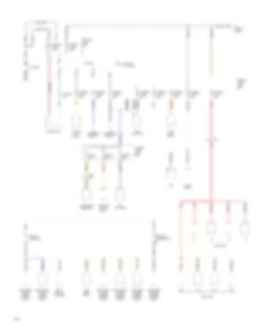
Power Distribution Wiring Diagram (1 of 6) for Infiniti Q45 1994
 https://portal-diagnostov.com/license.html
Automotive Electricians Portal FZCO
Automotive Electricians Portal FZCO
https://portal-diagnostov.com/license.html
https://portal-diagnostov.com/license.html
Automotive Electricians Portal FZCO
Automotive Electricians Portal FZCOList of elements for Power Distribution Wiring Diagram (1 of 6) for Infiniti Q45 1994:
- Abs actuator
- Alternator
- Battery
- Body
- Circuit breaker-1
- Circuit breaker-2
- Control module
- Cooling fan relay-1
- Eccs relay
- Ecm
- Fuse 36 10a
- Fuse 41 10a
- Fuse 42 20a
- Fuse 43 20a
- Fuse box
- Fusible link &
- Fusible link a 30a
- Fusible link b 30a
- Fusible link box
- Fusible link c 25a
- Fusible link d 75a
- Fusible link g 30a
- Fusible link h 25a
- Fusible link i 25a
- Fusible link j 30a
- Fusible link k 120a
- Fusible link m 100a
- Injectors
- Left front power seat control unit
- Left front power window control unit
- Left rear power window control unit
- Left smj
- Nca
- Red
- Right front power seat control unit
- Right front power window control unit
- Right rear power window control unit
- Smj
- Sun roof relay
- Tcs pump relay
- Telephone receiver
- Throttle motor relay
- To accessory relay-1
- To accessory relay-2
- To fuses 14, 15, 31-39
- To fusible link f
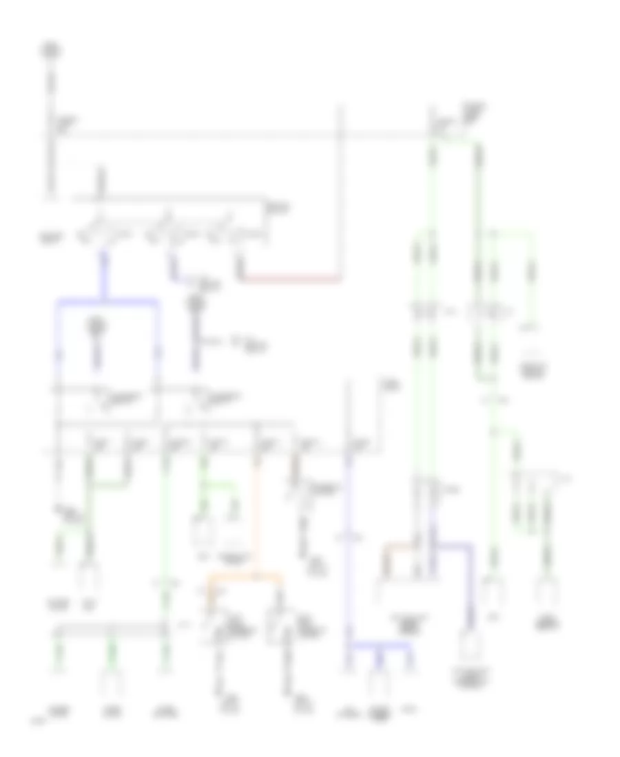
Power Distribution Wiring Diagram (2 of 6) for Infiniti Q45 1994
 https://portal-diagnostov.com/license.html
Automotive Electricians Portal FZCO
Automotive Electricians Portal FZCO
https://portal-diagnostov.com/license.html
https://portal-diagnostov.com/license.html
Automotive Electricians Portal FZCO
Automotive Electricians Portal FZCOList of elements for Power Distribution Wiring Diagram (2 of 6) for Infiniti Q45 1994:
- (left"a"
- (left"c"
- Acc
- Accessory relay-1
- Accessory relay-2
- Auto amp
- Bcm
- Blower motor
- Cd changer
- Cigarette
- Cigarette lighter
- Combination meter
- Daytime light cancel control unit (canada)
- Daytime light cancel relay (canada)
- Diode
- Ecm
- From fusible link a
- From fusible link m
- Fuse block
- Fuse 10 10a
- Fuse 11 20a
- Fuse 12 15a
- Fuse 29 20a
- Fuse 40 10a
- Fuse 7 15a
- Fuse 8 15a
- Fuse 9 10a
- Fusible link & fuse box
- Fusible link f 30a
- G900
- G900 (left "a" pillar)
- G905
- Ignition switch
- J/c
- J/c 3
- J/c 6
- J/c 8
- Left
- Lighter
- N11
- Off
- Pillar)
- Power antenna timer
- Radio
- Rear
- Right
- Smj
- Start
- Starter relay
- Theft warning relay-2
- Throttle control module
- To ignition relay-2
- Washer motor
- Wiper amplifier
- Wiper motor
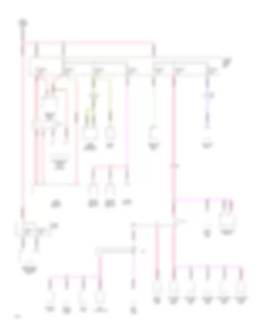
Power Distribution Wiring Diagram (3 of 6) for Infiniti Q45 1994
 https://portal-diagnostov.com/license.html
Automotive Electricians Portal FZCO
Automotive Electricians Portal FZCO
https://portal-diagnostov.com/license.html
https://portal-diagnostov.com/license.html
Automotive Electricians Portal FZCO
Automotive Electricians Portal FZCOList of elements for Power Distribution Wiring Diagram (3 of 6) for Infiniti Q45 1994:
- 10a
- 15a
- 20a
- Combination meter
- Courtesy lamp relay
- Daytime light control unit (canada)
- Fog lamp relay
- From fusible link m
- Fuse block
- Fuse 14
- Fuse 15
- Fuse 31
- Fuse 32
- Fuse 33
- Fuse 34
- Fuse 37
- Fuse 38
- Fuse 39
- Fusible link & fuse box
- Hazard switch
- Headlamp relay unit
- Horn relay
- Interior lamp
- J/c 1
- J/c 6
- J/c 8
- Key illumination
- Left
- Left foot lamp
- Left front step lamp
- Left rear step lamp
- Rear window defogger relay
- Red
- Remote control relay-1
- Remote control relay-2
- Right foot lamp
- Right front step lamp
- Right rear step lamp
- Smj
- Spot lamp
- Theft warning horn relay
- Theft warning relay-1
- Trunk room lamp
- Vanity mirror lamp
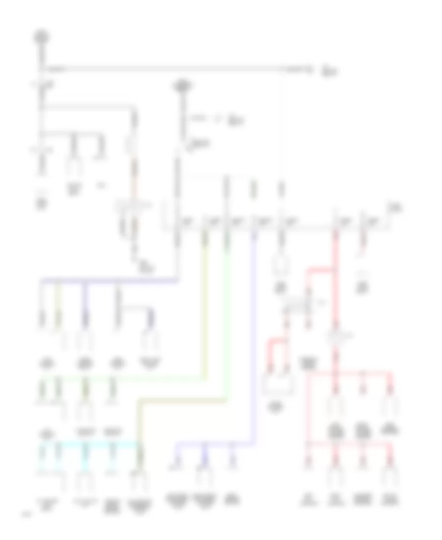
Power Distribution Wiring Diagram (4 of 6) for Infiniti Q45 1994
 https://portal-diagnostov.com/license.html
Automotive Electricians Portal FZCO
Automotive Electricians Portal FZCO
https://portal-diagnostov.com/license.html
https://portal-diagnostov.com/license.html
Automotive Electricians Portal FZCO
Automotive Electricians Portal FZCOList of elements for Power Distribution Wiring Diagram (4 of 6) for Infiniti Q45 1994:
- "1" position switch
- (left "a" pillar)
- A/t control unit
- Aac-iac valve solenoid
- Abs control unit
- Ascd hold relay
- Block
- Canister control solenoid
- Ecm
- Egr control solenoid
- F11
- From accessory relay-1
- From ignition switch
- Fuel pump relay
- Fuel pump rlay
- Full-active suspension control unit
- Fuse
- Fuse 1 10a
- Fuse 2 10a
- Fuse 27 15a
- Fuse 28 15a
- Fuse 3 15a
- Fuse 4 10a
- Fuse 5 10a
- G900
- Hicas control unit
- Ignition coil relay
- Ignition relay-1
- Ignition relay-2
- Inhibitor switch
- J/c 2
- J/c 7
- J/c f
- Left
- Left front power seat control unit
- Left heated oxygen sensor
- Left vct solenoid
- Multi-valve unit
- Oil cooler fan relay
- P12
- Red
- Right front power seat control unit
- Right heated oxygen sensor
- Right vct solenoid
- Seat heater switch
- Shift lock control unit
- Smj
- Steering angle sensor
- Tcs control unit
- Theft warning relay
- Vehicle height control switch
Power Distribution Wiring Diagram (5 of 6) for Infiniti Q45 1994
 https://portal-diagnostov.com/license.html
Automotive Electricians Portal FZCO
Automotive Electricians Portal FZCO
https://portal-diagnostov.com/license.html
https://portal-diagnostov.com/license.html
Automotive Electricians Portal FZCO
Automotive Electricians Portal FZCOList of elements for Power Distribution Wiring Diagram (5 of 6) for Infiniti Q45 1994:
- A/c control unit
- A/c relay
- Alternator
- Alternator resistor
- Ascd hold relay
- Ascd switch
- Audio amplifier
- Auto amp
- Bcm
- Block
- Blower high relay
- C12
- Combination meter
- Cooling fan relay-1
- Cooling fan relay-2 (a/t)
- Daytime light cancel relay (canada)
- Daytime light control unit (canada)
- Diagnostic information display control unit
- From ignition relay-2
- Fuel filler lid opener actuator
- Full-active suspension control unit
- Fuse
- Fuse 13 10a
- Fuse 16 10a
- Fuse 17 20a
- Fuse 18 15a
- Fuse 19 10a
- Fuse 22 10a
- Fuse 23 15a
- Fuse 24 10a
- Fuse 25 10a
- Fuse 26 10a
- Fuses 20 & 21
- G900 (left "a" pillar)
- H10
- Hazard switch
- Ignition relay-1
- Intake door motor
- J/c 1
- J/c 5
- J/c 6
- Key switch
- Pnk
- Rear lamp switch
- Rear window defogger
- Red
- Shift lock control unit
- Smj
- Sunroof relay
- Telephone hand set
- Telephone receiver
- Throttle meter module
- Throttle meter relay
- Trunk lid opener actuator
Power Distribution Wiring Diagram (6 of 6) for Infiniti Q45 1994
 https://portal-diagnostov.com/license.html
Automotive Electricians Portal FZCO
Automotive Electricians Portal FZCO
https://portal-diagnostov.com/license.html
https://portal-diagnostov.com/license.html
Automotive Electricians Portal FZCO
Automotive Electricians Portal FZCOList of elements for Power Distribution Wiring Diagram (6 of 6) for Infiniti Q45 1994:
- 10a
- A/t control unit
- Airbag contol unit
- Auto amp
- Bcm
- Cd changer
- Clock
- Combination meter
- From ignition relay-1
- Fuse 20
- Fuse 21
- Fuse block
- Hicas hicas control control unit unit (touring sedan)
- J/c 6
- J/c 8
- Left front power window sub-switch
- Left keyhole illumination
- Left rear power window control unit
- Left rear power window sub-switch
- Power antenna timer
- Power window main switch
- Radio
- Right front power seat control unit
- Right front power seat switch
- Right front power window control unit
- Right front power window sub-switch
- Right keyhole illumination
- Right rear power window control unit
- Right rear power window sub-switch
- Smj
- Throttle control module
POWER DOOR LOCKS
Door Lock Wiring Diagram for Infiniti Q45 1994
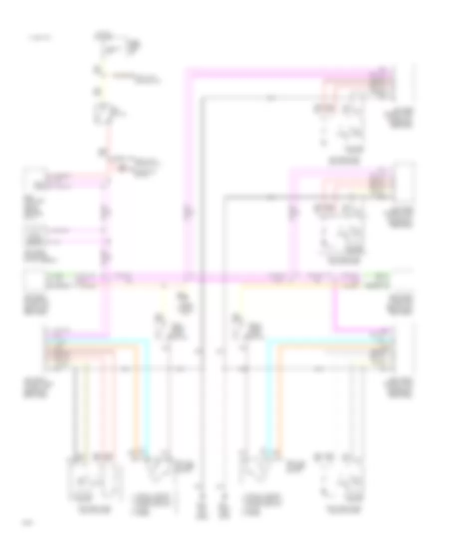 https://portal-diagnostov.com/license.html
Automotive Electricians Portal FZCO
Automotive Electricians Portal FZCO
https://portal-diagnostov.com/license.html
https://portal-diagnostov.com/license.html
Automotive Electricians Portal FZCO
Automotive Electricians Portal FZCOList of elements for Door Lock Wiring Diagram for Infiniti Q45 1994:
- (inside left rear door)
- (left kick panel)
- (right side of i/p)
- Airbag control unit
- Body computer
- C 1995 vftc
- Control unit
- Control unit (below left front seat)
- Control unit (below right
- Control unit (inside left front door)
- Control unit (inside right
- Control unit (inside right front door)
- Data lines
- Detention switch
- Front seat)
- Fuse 19 10a
- Fuse block (left i/p)
- G200
- G201
- Hot at all times
- Key switch
- Left front door lock actuator
- Left front door switch
- Left front power seat
- Left front power window
- Left key cylinder switch
- Left rear
- Left rear door lock actuator
- Lock
- Lock & unlock switch
- Lock knob
- Lock-between full
- Lock-full stroke
- Module (behind left side of i/p)
- Power window
- Rear door)
- Right front
- Right front door lock actuator
- Right front door switch
- Right front power seat
- Right key cylinder switch
- Right rear
- Right rear door lock actuator
- Shift lock control unit
- Stroke & neutral
- Switch
- Switch assembly
- Tamper
- Un- lock
- Unlock
Keyless Entry Wiring Diagram (1 of 2) for Infiniti Q45 1994
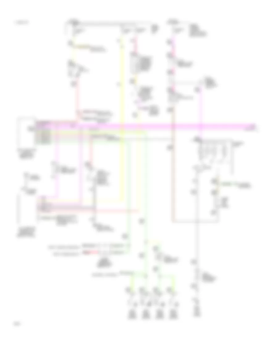 https://portal-diagnostov.com/license.html
Automotive Electricians Portal FZCO
Automotive Electricians Portal FZCO
https://portal-diagnostov.com/license.html
https://portal-diagnostov.com/license.html
Automotive Electricians Portal FZCO
Automotive Electricians Portal FZCOList of elements for Keyless Entry Wiring Diagram (1 of 2) for Infiniti Q45 1994:
- (center rear of trunk lid)
- (left kick panel)
- (upper left
- (upper right side of i/p)
- 1995 vftc c
- Assembly
- Body computer module (behind left side of i/p)
- Courtesy lamp relay
- Data lines
- Detention switch
- Diode
- Door
- Feeder cable
- Fuse & fusible link box (right side of engine compt)
- Fuse 19 10a
- Fuse 21 10a
- Fuse 22 10a
- Fuse 38 10a
- Fuse block (left i/p)
- G200
- G404 (left rear side of trunk)
- Hot at all times
- Interior lamp
- J/c-4 (behind instrument cluster)
- J/c-5 (upper left side of i/p)
- J/c-6 (behind upper left side of i/p)
- J/c-8 (below left rear seat)
- Key illumination
- Key switch
- Left front door switch
- Left rear door switch
- Multi-remote control unit
- Off
- Pnk
- Rear of trunk)
- Red
- Remote control relays 1 & 2 (exterior lights system)
- Right front door switch
- Right rear door switch
- Shift lock control unit
- Switch (in glove box)
- Theft warning horn relay
- Theft warning relay-1
- Trunk lid opener cancel
- Trunk lid opener solenoid (center rear of trunk)
- Trunk room lamp
- Trunk room lamp switch
- Trunk/ fuel lid opener switch
- Window antenna
Keyless Entry Wiring Diagram (2 of 2) for Infiniti Q45 1994
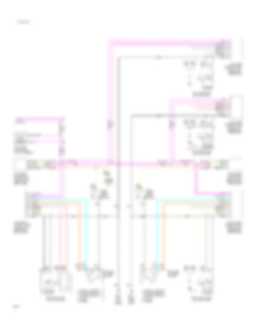 https://portal-diagnostov.com/license.html
Automotive Electricians Portal FZCO
Automotive Electricians Portal FZCO
https://portal-diagnostov.com/license.html
https://portal-diagnostov.com/license.html
Automotive Electricians Portal FZCO
Automotive Electricians Portal FZCOList of elements for Keyless Entry Wiring Diagram (2 of 2) for Infiniti Q45 1994:
- (below right
- (inside left rear door)
- (inside right
- (inside right front door)
- (left kick panel)
- (right side of i/p)
- Airbag control unit
- C 1995 vftc
- Control unit
- Control unit (below left front seat)
- Control unit (inside left front door)
- Front seat)
- G200
- G201
- Left front door lock actuator
- Left front door switch
- Left front power seat
- Left front power window
- Left key cylinder switch
- Left rear
- Left rear door lock actuator
- Lock
- Lock & unlock switch
- Lock knob
- Lock-between full
- Lock-full stroke
- Power seat
- Power window
- Rear door)
- Right front
- Right front door lock actuator
- Right front door switch
- Right key cylinder switch
- Right rear
- Right rear door lock actuator
- Stroke & neutral
- Switch
- Switch assembly
- Tamper
- Un- lock
- Unlock
POWER SEATS
Heated Seats Wiring Diagram for Infiniti Q45 1994
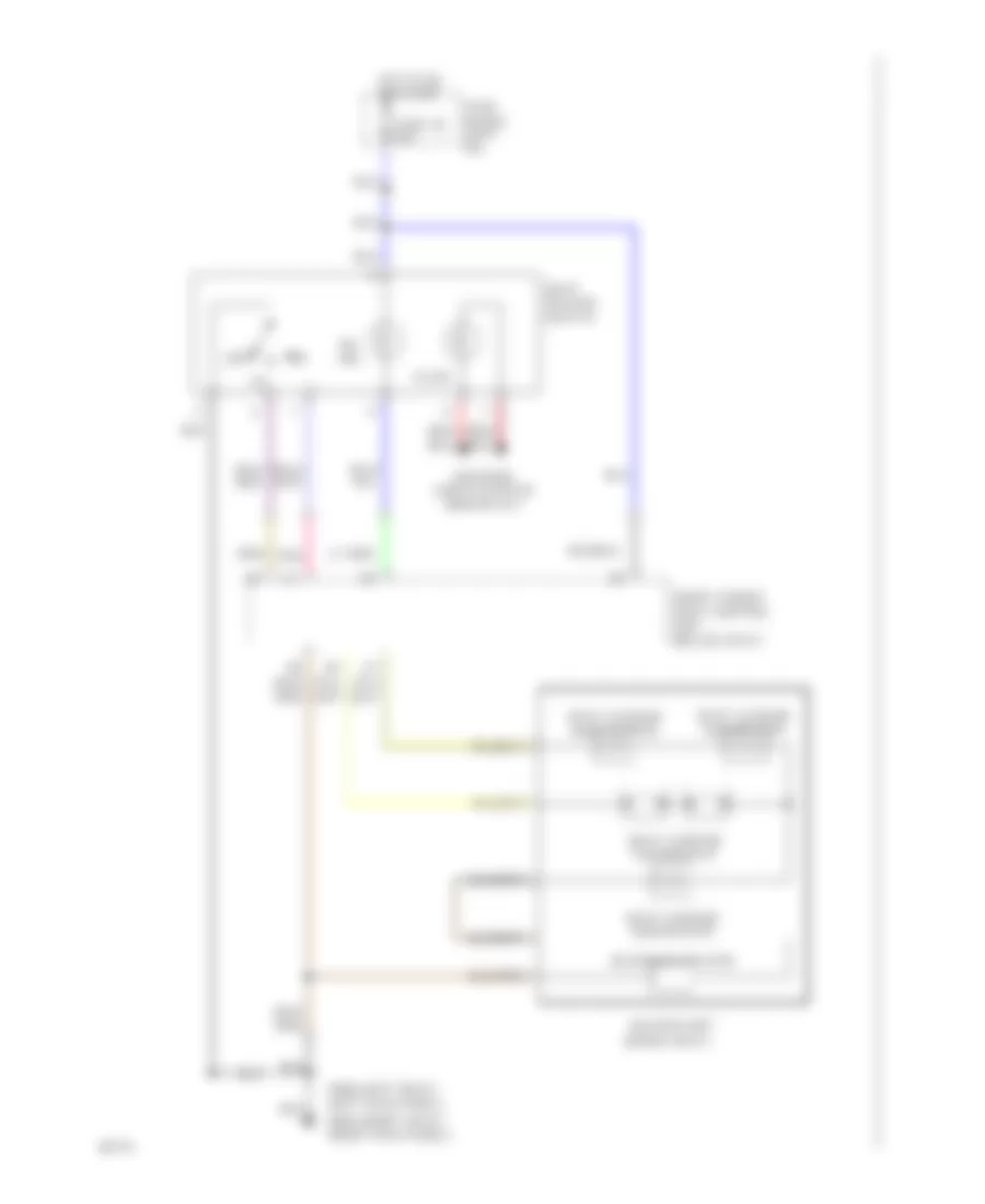 https://portal-diagnostov.com/license.html
Automotive Electricians Portal FZCO
Automotive Electricians Portal FZCO
https://portal-diagnostov.com/license.html
https://portal-diagnostov.com/license.html
Automotive Electricians Portal FZCO
Automotive Electricians Portal FZCOList of elements for Heated Seats Wiring Diagram for Infiniti Q45 1994:
- (inside seat)
- Front power seat control unit (below seat)
- Fuse 30 10a
- Fuse block (left i/p)
- G200 (left seat) (left kick panel)
- G203 (right seat) (right kick panel)
- Heater unit
- Hot in on or start
- Illum.
- Interior lights system (rheostat)
- Off
- On ind.
- Pnk
- Seat cushion main heater
- Seat cushion sub-heater
- Seat cushion thermostat
- Seat heater switch
- Seatback heater
Right Power Seat Wiring Diagram for Infiniti Q45 1994
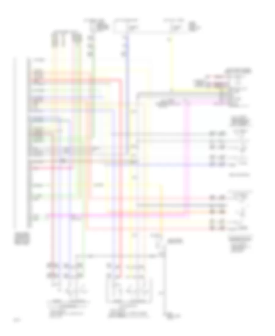 https://portal-diagnostov.com/license.html
Automotive Electricians Portal FZCO
Automotive Electricians Portal FZCO
https://portal-diagnostov.com/license.html
https://portal-diagnostov.com/license.html
Automotive Electricians Portal FZCO
Automotive Electricians Portal FZCOList of elements for Right Power Seat Wiring Diagram for Infiniti Q45 1994:
- Battery
- Between fully
- Between fully down & up
- Between fully front & rear
- Body computer module
- C.b.
- Circuit breaker-1 (left side of i/p)
- Data a
- Data b
- Data grd
- Down & up fully up
- Front & rear fully rear
- Fully down
- Fully front
- Fully rear
- Fully up
- Fuse 21 10a
- Fuse 30 15a
- Fuse block (left kick panel)
- G201 (right side of i/p)
- Grd
- Headrest device
- Heated seat circuit
- Hot at all times
- Hot in on or start
- Illum.
- Interior lights system
- Keyhole illum.
- Lifting device
- Limit switch
- Motor
- Pnk
- Reclining device
- Red
- Right front door switch
- Right front power seat control unit (below right front seat)
- Right front power seat switch assembly
- Sliding device
POWER TOP/SUNROOF
Power Top/Sunroof Wiring Diagrams for Infiniti Q45 1994
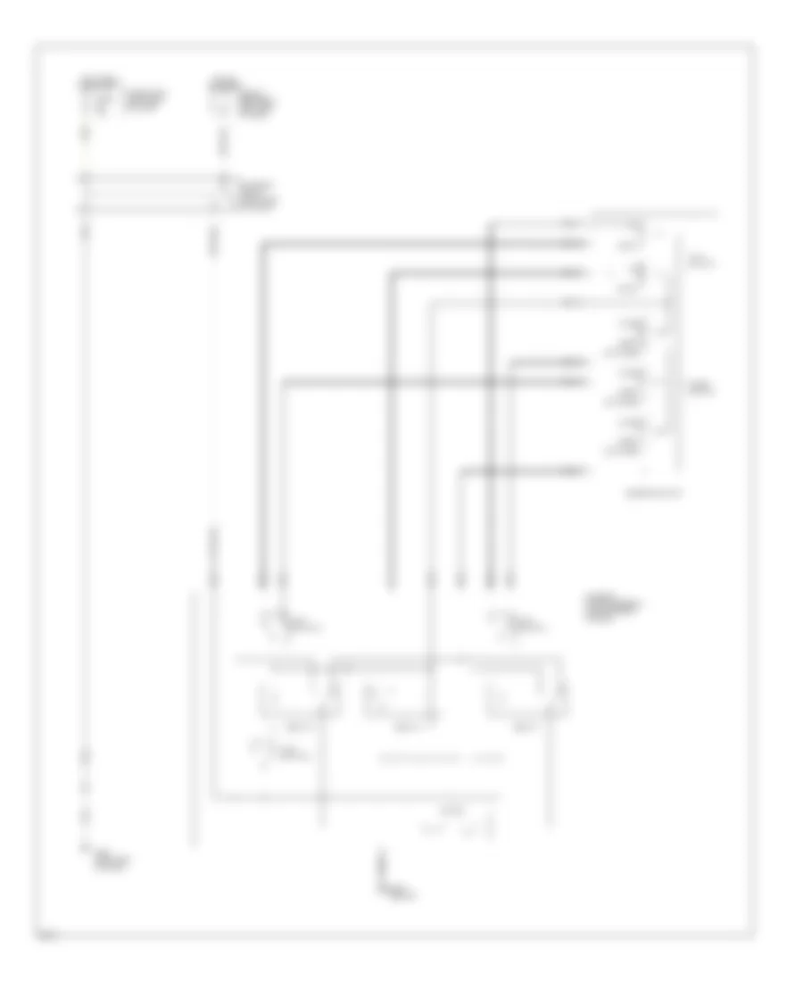 https://portal-diagnostov.com/license.html
Automotive Electricians Portal FZCO
Automotive Electricians Portal FZCO
https://portal-diagnostov.com/license.html
https://portal-diagnostov.com/license.html
Automotive Electricians Portal FZCO
Automotive Electricians Portal FZCOList of elements for Power Top/Sunroof Wiring Diagrams for Infiniti Q45 1994:
- Auto open
- Body ground
- Circuit breaker 2 (left side of dash)
- Close
- Down
- Fuse 10a
- Fuse block (left side of dash)
- G200 (left side of dash)
- Hot at all times
- Hot in run or start
- Limit switch 1
- Limit switch 2
- Limit switch 3
- Motor
- Nca
- Open
- Relay 1
- Relay 2
- Relay 3
- Slide switch
- Sunroof motor assembly (center front of roof)
- Sunroof relay (left side of dash)
- Sunroof switch
- Tilt switch
POWER WINDOWS
Power Window Wiring Diagram for Infiniti Q45 1994
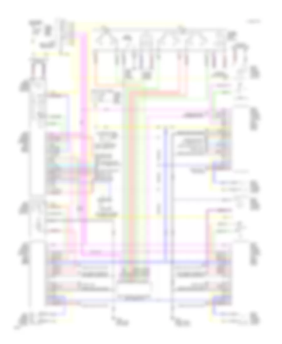 https://portal-diagnostov.com/license.html
Automotive Electricians Portal FZCO
Automotive Electricians Portal FZCO
https://portal-diagnostov.com/license.html
https://portal-diagnostov.com/license.html
Automotive Electricians Portal FZCO
Automotive Electricians Portal FZCOList of elements for Power Window Wiring Diagram for Infiniti Q45 1994:
- 1995 vftc c
- Actuator
- Auto
- Body control module (bcm) (left side of i/p)
- Circuit breaker 2 (left side of i/p)
- Door handle sw.
- Door handle switch
- Door lock
- Door lock actuator
- Door lock key cylinder switch
- Fuse block (left side of i/p)
- Fuse 10a
- Fuse block (left side of i/p)
- G200 (left kick panel)
- G400 (left side of trunk)
- G403 (right rear wheel well)
- Hot at all times
- Hot in run or start
- Interior lights system
- J/c 8 (below left rear seat)
- Left front power window control unit (left front door)
- Left front power window motor
- Left front power window switch
- Left rear cigarette lighter illumination
- Left rear power window control unit (left rear door)
- Left rear power window motor
- Left rear power window switch
- Lock switch
- Nca
- Power window main switch
- Red
- Right front power window control unit (right front door)
- Right front power window motor
- Right front power window switch
- Right rear cigarette lighter illumination
- Right rear power window control unit (right rear door)
- Right rear power window motor
- Right rear power window switch
- Step lamp
RADIO
Radio Wiring Diagrams for Infiniti Q45 1994
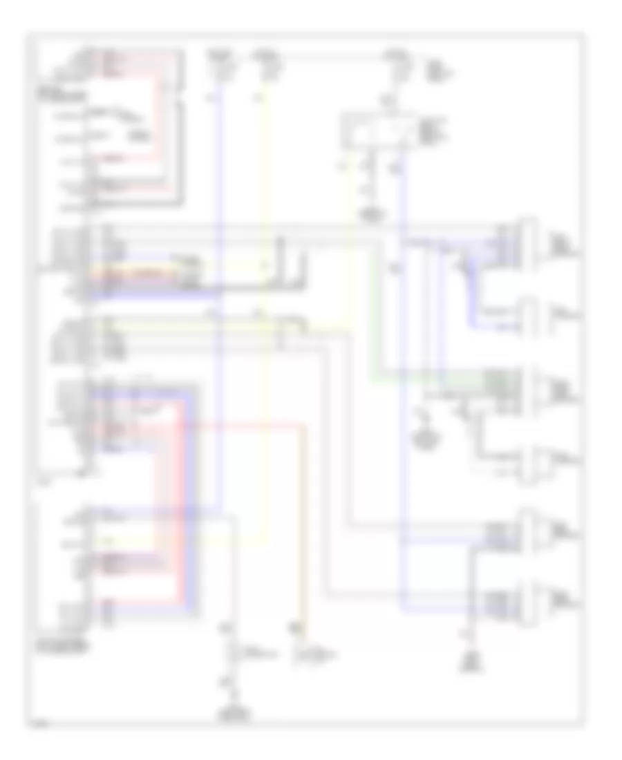 https://portal-diagnostov.com/license.html
Automotive Electricians Portal FZCO
Automotive Electricians Portal FZCO
https://portal-diagnostov.com/license.html
https://portal-diagnostov.com/license.html
Automotive Electricians Portal FZCO
Automotive Electricians Portal FZCOList of elements for Radio Wiring Diagrams for Infiniti Q45 1994:
- A/c control unit
- Acc
- Antenna in
- Antenna sig
- Audio amp relay (behind right kick panel)
- Back up
- Battery backup
- Case gnd
- Cd auto changer (right rear corner of luggage compt)
- Cd lh in (+)
- Cd lh in (-)
- Cd rh in (+)
- Cd rh in (-)
- Data ground
- Fr lh (+) amp
- Fr lh (-) amp
- Fr rh (+) amp
- Fr rh (-) amp
- Fuse 10a
- Fuse 20a
- Fuse block (left kick panel)
- G200 (bottom of left kick panel)
- G203 (right kick panel)
- G316 (right front door sill)
- G403 (right rear wheelwell)
- Gnd
- Ground
- Hot at all times
- Hot in on or acc
- Illum
- Illum max
- Interior lights system
- Joint connector 1
- Left front door speaker
- Left rear speaker
- Left tweeter
- Lh (+) out
- Lh (-) out
- M113
- M114
- M77
- M78
- Nca
- On sig
- On signal
- Power antenna
- R ch (+) in
- R ch (+) out
- R ch (-) in
- R ch (-) out
- Radio
- Receiver (left rear corner of luggage compt)
- Red
- Req
- Rh (+) out
- Rh (-) out
- Right front door speaker
- Right rear speaker
- Right tweeter
- Rod antenna
- Rr lh (+) amp
- Rr lh (-) amp
- Rr rh (+) amp
- Rr rh (-) amp
- Rxd
- Txd
- Window antenna
SHIFT INTERLOCKS
Shift Interlock Wiring Diagram for Infiniti Q45 1994
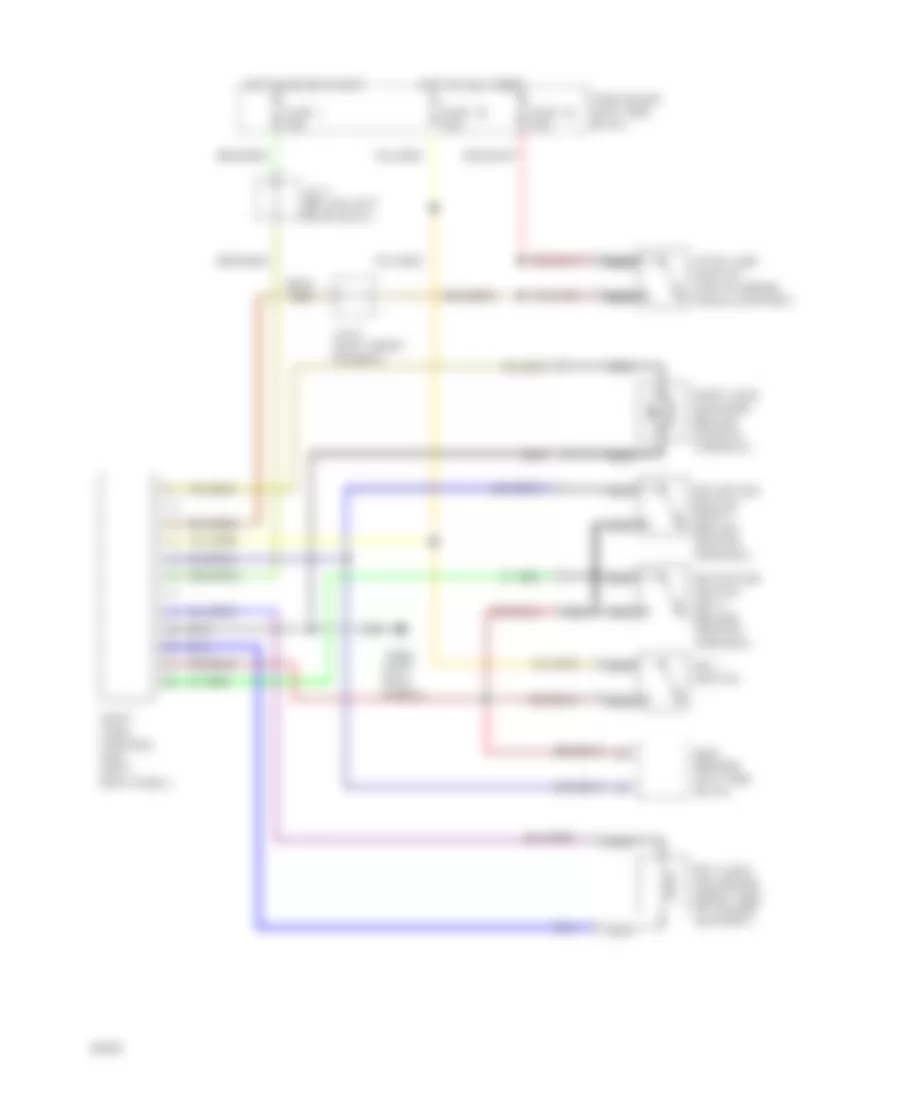 https://portal-diagnostov.com/license.html
Automotive Electricians Portal FZCO
Automotive Electricians Portal FZCO
https://portal-diagnostov.com/license.html
https://portal-diagnostov.com/license.html
Automotive Electricians Portal FZCO
Automotive Electricians Portal FZCOList of elements for Shift Interlock Wiring Diagram for Infiniti Q45 1994:
- Bcm (behind left side of i/p)
- Detention switch (key) (below center console)
- Detention switch (shift) (below center console)
- Fuse 1 10a
- Fuse 18 15a
- Fuse 19 10a
- Fuse block (left side of i/p)
- G200 (left kick panel)
- Hot at all times
- Hot in on or start
- J/c 6 (left front fender)
- J/c 7 (below left rear seat)
- Key lock soloenoid (right side of column support)
- Key switch
- Nca
- Shift lock control unit (left kick panel)
- Shift lock solenoid (below center console)
- Stop lamp switch (top of brake pedal support)
STARTING/CHARGING
Charging Wiring Diagram for Infiniti Q45 1994
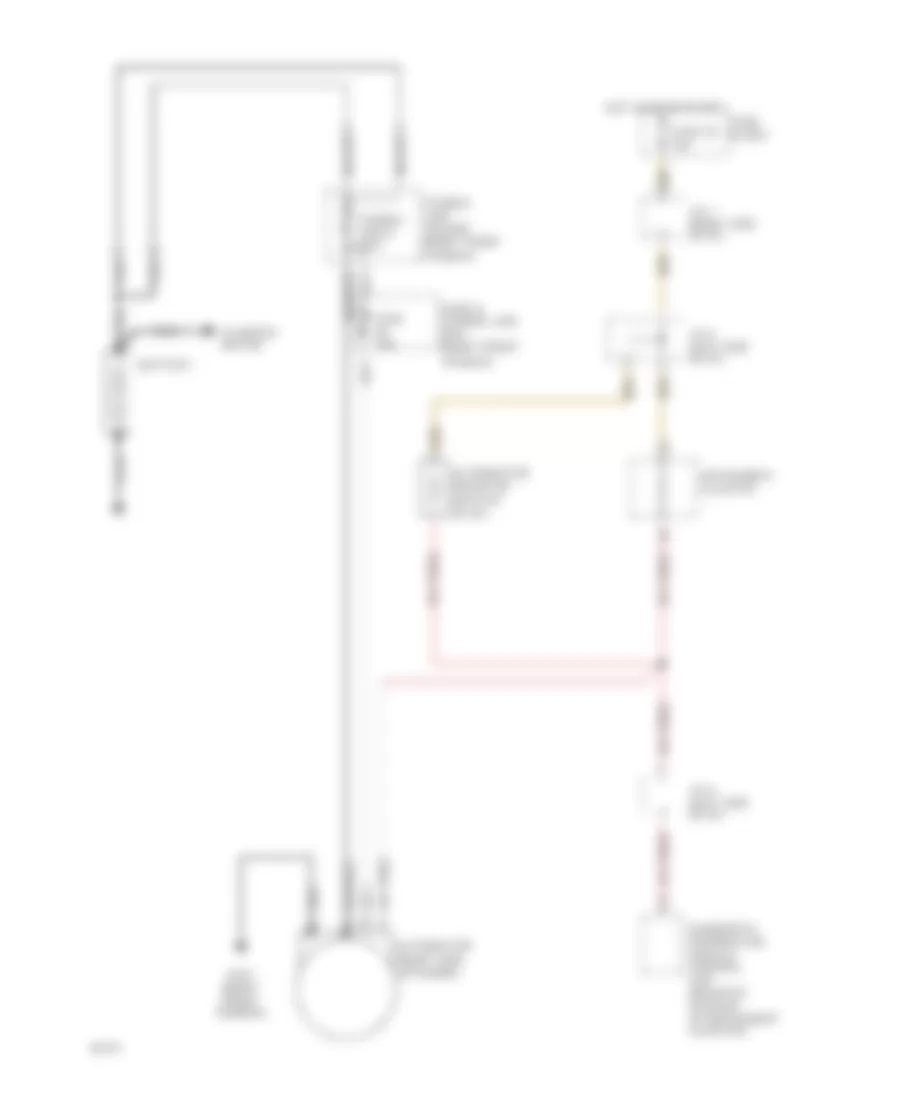 https://portal-diagnostov.com/license.html
Automotive Electricians Portal FZCO
Automotive Electricians Portal FZCO
https://portal-diagnostov.com/license.html
https://portal-diagnostov.com/license.html
Automotive Electricians Portal FZCO
Automotive Electricians Portal FZCOList of elements for Charging Wiring Diagram for Infiniti Q45 1994:
- (right side of engine)
- Alternator
- Alternator resistor (center
- Battery
- Diagnostic information display control unit (mounted on back of instrument cluster)
- Fender)
- Fuse & fusible link box (right front
- Fuse 10a
- Fuse 25 10a
- Fuse block
- Fusible link holder (right front
- G101 (right front fender)
- Hot in on or start
- Instrument cluster
- J/c 1 (right side of i/p)
- J/c 5 (left side of i/p)
- Nca
- Of i/p)
- Starter motor
Starting Wiring Diagram for Infiniti Q45 1994
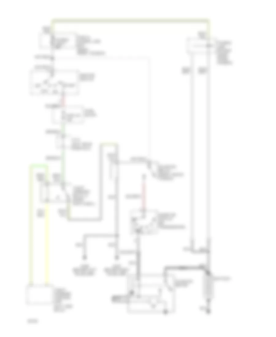 https://portal-diagnostov.com/license.html
Automotive Electricians Portal FZCO
Automotive Electricians Portal FZCO
https://portal-diagnostov.com/license.html
https://portal-diagnostov.com/license.html
Automotive Electricians Portal FZCO
Automotive Electricians Portal FZCOList of elements for Starting Wiring Diagram for Infiniti Q45 1994:
- (left rear door sill)
- (left side of i/p)
- (right front fender)
- Acc
- Battery
- Fuse & fusible link box
- Fuse 40 10a
- Fuse block
- Fusible link f 30a
- Fusible link holder
- G106 (behind left headlamp)
- G107 (behind right headlamp)
- Ignition switch
- Inhibitor switch (on transmission)
- J/c 8
- Nca
- Off
- Red
- Start
- Starter motor
- Starter relay (right shock tower)
- Theft warning control unit
- Theft warning relay 2 (right kick panel)
SUPPLEMENTAL RESTRAINTS
Supplemental Restraint Wiring Diagram for Infiniti Q45 1994
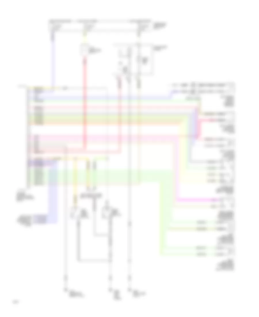 https://portal-diagnostov.com/license.html
Automotive Electricians Portal FZCO
Automotive Electricians Portal FZCO
https://portal-diagnostov.com/license.html
https://portal-diagnostov.com/license.html
Automotive Electricians Portal FZCO
Automotive Electricians Portal FZCOList of elements for Supplemental Restraint Wiring Diagram for Infiniti Q45 1994:
- 10a
- Air bag control unit (below center of i/p)
- Air bag ind.
- Data link connector for consult (left side of i/p)
- Front crash zone sensor (center front of radiator)
- Fuse 21
- Fuse 25
- Fuse 5
- Fuse block (left side of i/p)
- G121 (center of safety wall)
- G200 (left kick panel)
- G201 (right side of i/p)
- Hot at all times
- Hot in on or start
- Instrument panel
- J/c 6 (left side of i/p)
- Left airbag module (top of steering column)
- Left front door switch
- Left front power seat control unit
- Left seat belt pretensioner (bottom of left "b" pillar)
- Nca
- Pnk
- Red
- Right airbag module 1 (right side of i/p)
- Right airbag module 2 (right side of i/p)
- Right seat belt pretensioner (bottom of right "b" pillar)
- Seat belt ind.
- Seat belt switch
- Spiral cable
- Tunnel and safing sensor (below center of i/p)
TRANSMISSION
Transmission Wiring Diagram for Infiniti Q45 1994
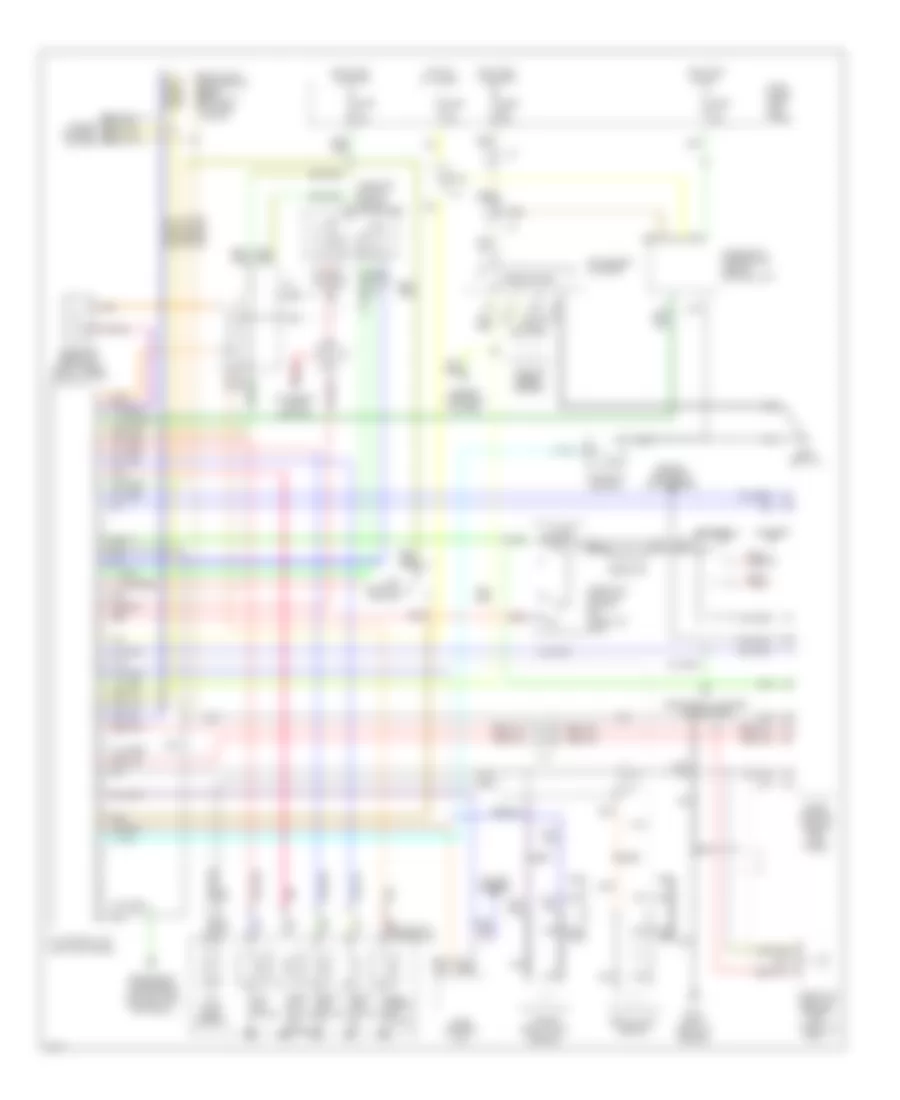 https://portal-diagnostov.com/license.html
Automotive Electricians Portal FZCO
Automotive Electricians Portal FZCO
https://portal-diagnostov.com/license.html
https://portal-diagnostov.com/license.html
Automotive Electricians Portal FZCO
Automotive Electricians Portal FZCOList of elements for Transmission Wiring Diagram for Infiniti Q45 1994:
- (left kick panel)
- (right front of engine)
- 1-2
- 1st position switch
- A/t control unit
- A/t fluid temp. sensor
- All times
- Ascd control unit
- Automatic transaxle
- Battery
- Closed throttle
- Cruise control
- Cruise control system
- Data link connector (for consult) (in fuse block)
- Diagnostic information display control unit
- Dropping resistor (right front shock tower)
- Eccs control module (right kick panel)
- Eccs relay
- Electronic suspension (active susp control unit) (optional)
- Engine controls (maf sensor)
- Engine controls system
- Exterior lights (backup)
- Fuse 10a
- Fuse block (left kick panel)
- G119
- G200 (left i/p)
- Hot at
- Hot in on or acc
- Hot in on or start
- Inhibitor switch (side of transaxle)
- Instrument cluster
- Instrument cluster (tachometer)
- J/c
- Kickdown switch
- Line press. sol. valve
- Nca
- Over- run clutch sol. valve
- Pnk
- Red
- Resistor
- Revolution sensor
- Sensor
- Shift sol. valve a
- Shift sol. valve b
- Speedometer
- Tcc sol. valve
- Throttle position sensor (on throttle body)
- Throttle position switch (on throttle body)
- Turbine revolution
- Vehicle speed sensor
- Wot
TRUNK, TAILGATE, FUEL DOOR
Trunk & Fuel Door Release Wiring Diagram for Infiniti Q45 1994
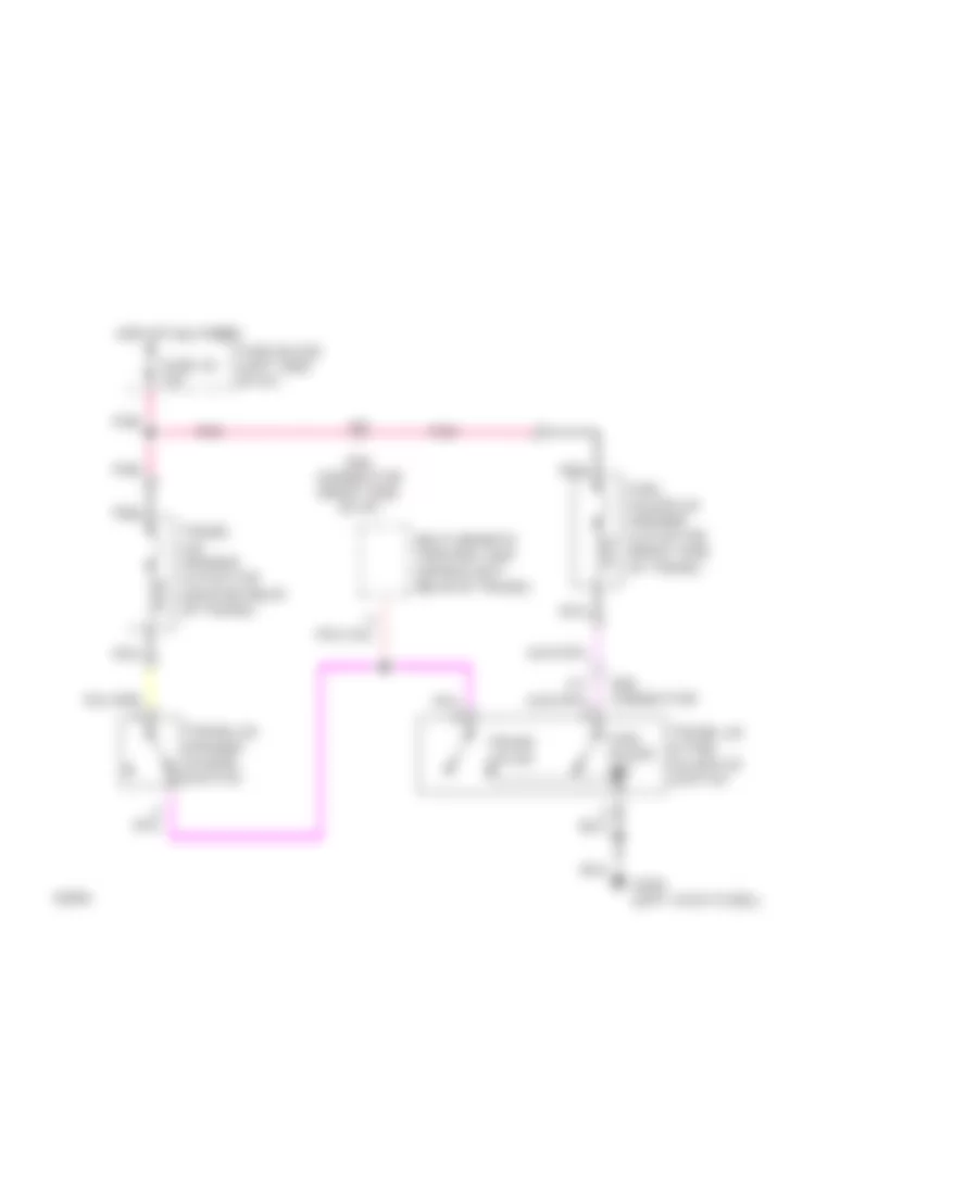 https://portal-diagnostov.com/license.html
Automotive Electricians Portal FZCO
Automotive Electricians Portal FZCO
https://portal-diagnostov.com/license.html
https://portal-diagnostov.com/license.html
Automotive Electricians Portal FZCO
Automotive Electricians Portal FZCOList of elements for Trunk & Fuel Door Release Wiring Diagram for Infiniti Q45 1994:
- Fuel filler lid opener actuator (right side of trunk)
- Fuel filler sw
- Fuse 22 10a
- Fuse block (left side of i/p)
- G200 (left kick panel)
- Hot at all times
- Multi-remote control unit (upper left rear of trunk)
- Nca
- Pnk
- Smj connector
- Smj connector (right side of i/p)
- Trunk lid & fuel filler lid switch
- Trunk lid opener actuator (center rear of trunk)
- Trunk lid opener cancel switch
- Trunk lid sw
WARNING SYSTEMS
Warning System Wiring Diagrams for Infiniti Q45 1994
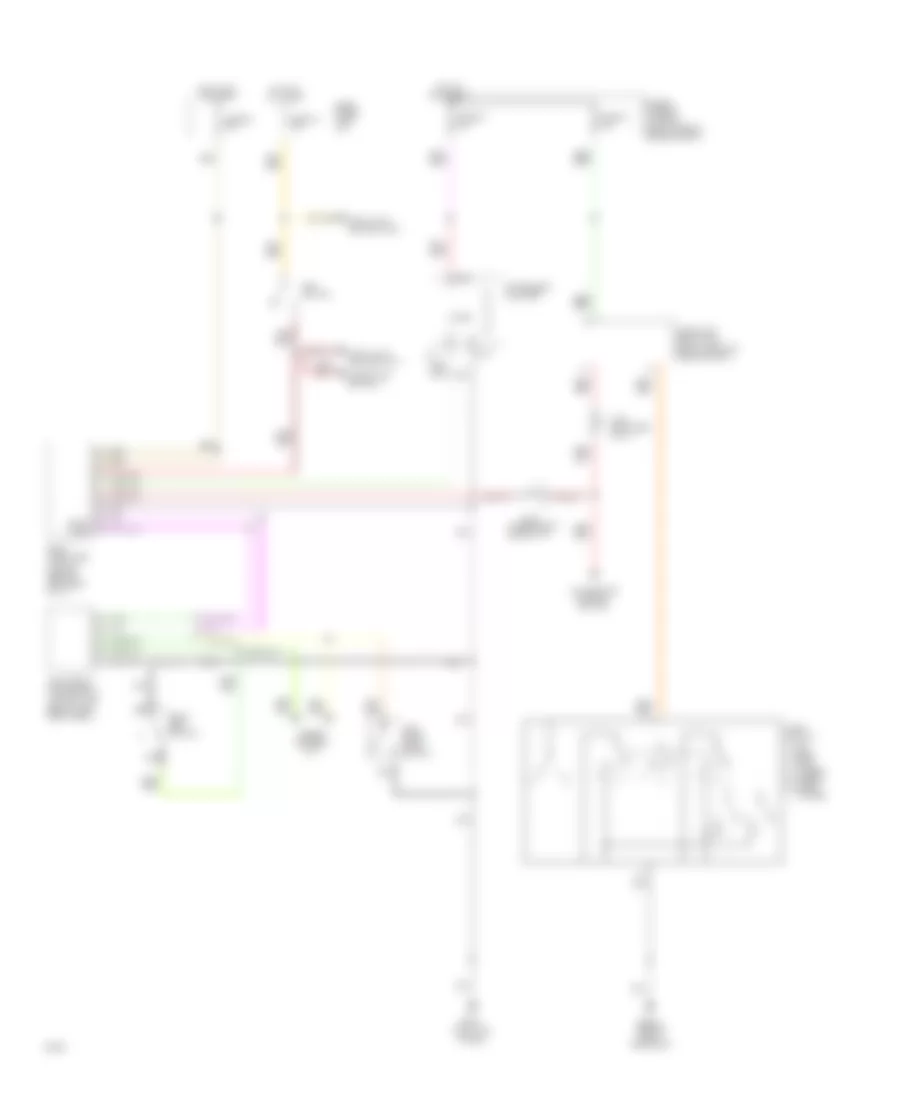 https://portal-diagnostov.com/license.html
Automotive Electricians Portal FZCO
Automotive Electricians Portal FZCO
https://portal-diagnostov.com/license.html
https://portal-diagnostov.com/license.html
Automotive Electricians Portal FZCO
Automotive Electricians Portal FZCOList of elements for Warning System Wiring Diagrams for Infiniti Q45 1994:
- control switch
- (behind right headlamp)
- (left kick panel)
- (right front of engine compt)
- (upper right side of i/p)
- A-11
- A-9
- Airbag control unit
- B-23
- Body computer
- Chime
- Control unit (below left front seat)
- Data lines
- Detention switch
- Fuse & fusible link box (right side of engine compt)
- Fuse 19 10a
- Fuse 25 10a
- Fuse 37 10a
- Fuse 38 10a
- Fuse block (left i/p)
- G107
- G200
- Headlamp relay unit
- Hot at all times
- Hot in on or start
- Illumination
- Instrument cluster
- J/c-2
- J/c-5 (left side of i/p)
- Key switch
- Left front door switch
- Left front power seat
- Light switch
- Module (behind left side of i/p)
- Nca
- Off
- Park head lo beam hi beam flash- to-pass
- Seat belt switch
- Shift lock control unit
WIPER/WASHER
Wiper/Washer Wiring Diagram for Infiniti Q45 1994
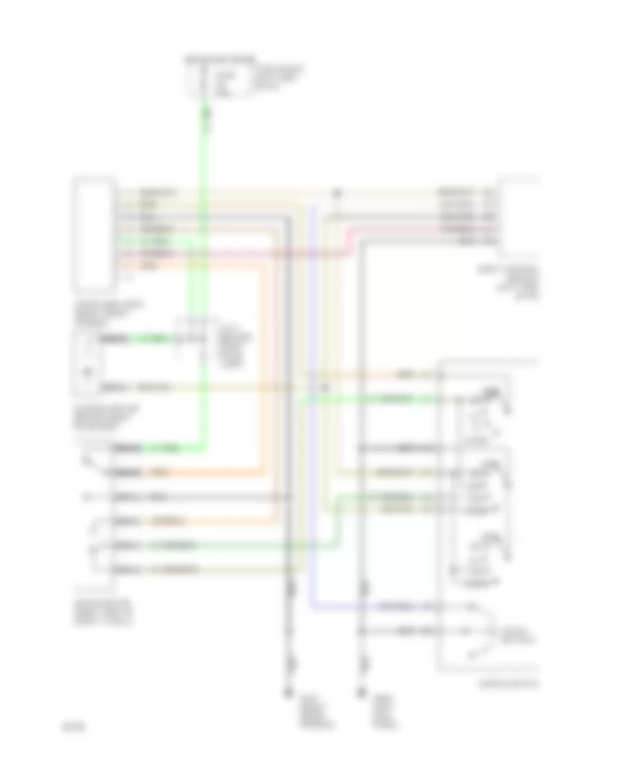 https://portal-diagnostov.com/license.html
Automotive Electricians Portal FZCO
Automotive Electricians Portal FZCO
https://portal-diagnostov.com/license.html
https://portal-diagnostov.com/license.html
Automotive Electricians Portal FZCO
Automotive Electricians Portal FZCOList of elements for Wiper/Washer Wiring Diagram for Infiniti Q45 1994:
- Body control module (left side of i/p)
- Fuse 20a
- Fuse block (left side of i/p)
- G101 (right front fender)
- G200 (left kick panel
- Hot in acc or on
- Int
- Inter- mittent
- J/c 3 (behind right head- lamp)
- Nca
- Off
- Wash
- Washer motor (behind right headlamp)
- Wiper amplifier (right front fender)
- Wiper motor (right side of safety wall)
- Wiper switch

 Čeština
 Dansk
Dansk Deutsch
 Ελληνικά
 English
 English
 Español
 Suomi
Suomi Français
 Français
 עברית
עברית Hrvatski
 Magyar
 Italiano
 日本語
日本語 한국어
한국어 Nederlands
 Polski
 Português
 Português
 Română
 Русский
 Slovenčina
 Slovenščina
 Svenska
 中文 (中国)
