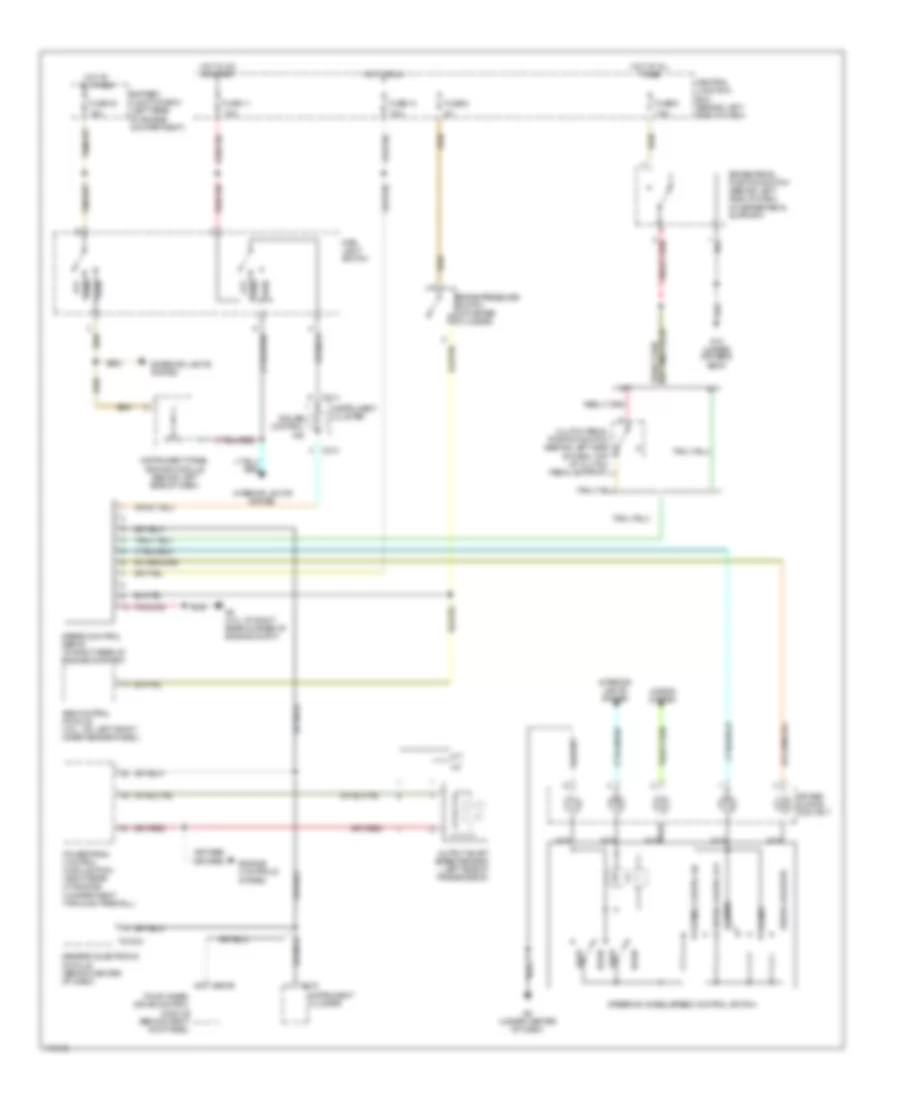
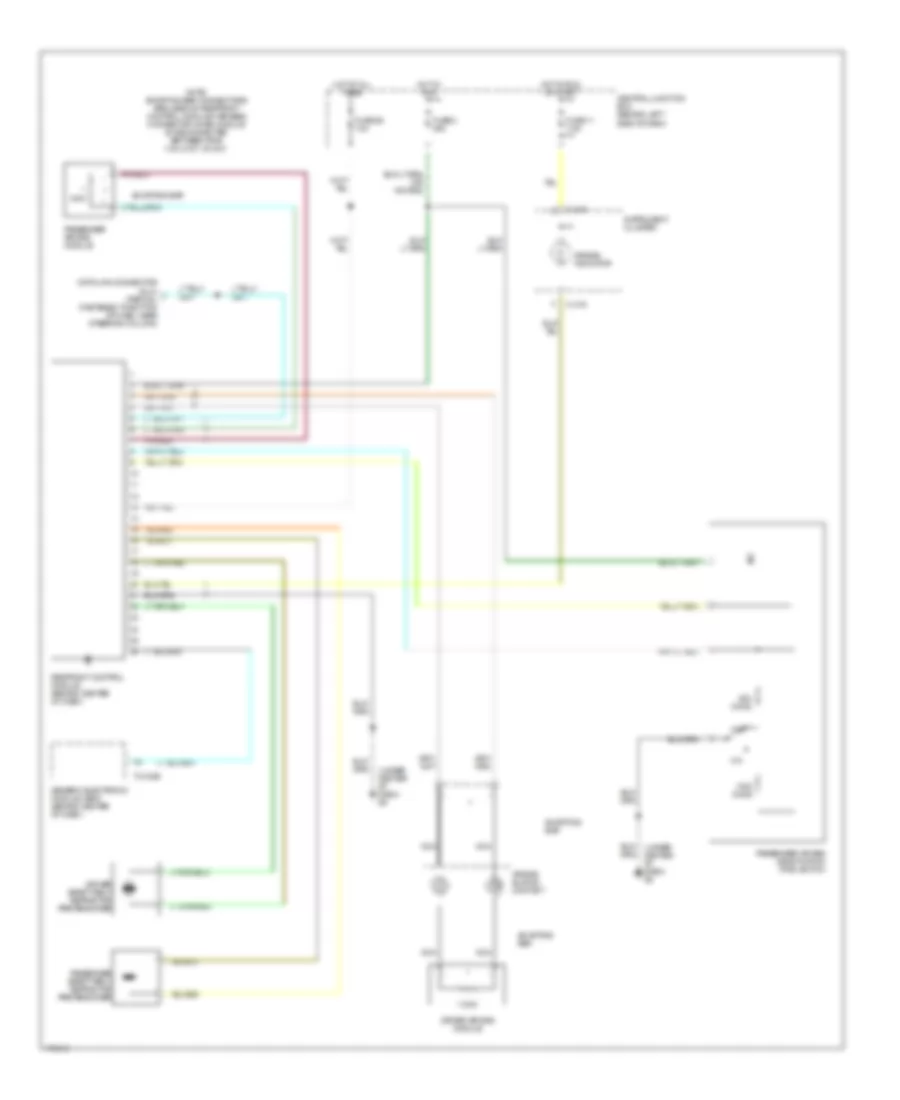
AIR CONDITIONING
Manual A/C Wiring Diagram for Mazda BSE 2003 4000
 https://portal-diagnostov.com/license.html
Automotive Electricians Portal FZCO
Automotive Electricians Portal FZCO
https://portal-diagnostov.com/license.html
https://portal-diagnostov.com/license.html
Automotive Electricians Portal FZCO
Automotive Electricians Portal FZCO
List of elements for Manual A/C Wiring Diagram for Mazda BSE 2003 4000:
- (4.0l: at left front corner of engine compt) g3
- (4.0l: at right rear corner of engine compt) g5
- (4.0l: behind left headlight) g1
- (at left kick panel) g7
- 2.3l
- A/c
- A/c clutch relay
- A/c clutch solenoid
- A/c compressor clutch diode
- A/c compressor cycling switch (in right side of engine compt, on a/c accumulator)
- A/c high pressure switch (near left side of engine)
- Battery junction box (left rear of engine compartment)
- Battery junction box (left rear of engine compt)
- Blower motor relay
- Blower motor switch
- Central junction box (behind left side of dash)
- Defrost
- Engine controls system
- Engine coolant temperature (ect) sensor (3.0l, 4.0l) (3.0l: on top left front of engine) (4.0l: on top front center of engine)
- Engine cooling fan motor (2.3l)
- Engine cooling fan relay (2.3l)
- Floor
- Flr/def
- Front function selector switch assembly
- Front heater blower motor resistor (right rear of engine compartment, near blower motor)
- Fuse 10a
- Fuse 20a
- Fuse 25a
- Fuse 30a
- Fuse 40a
- Fuse 7.5a
- G-232
- G-233
- G-234
- G3 (4.0l: at left front corner of engine compt)
- Heater blower motor (right rear of engine compt, on firewall)
- Hot at all times
- Hot in run
- Hot in run or start
- Illumination
- Interior lights system
- Max a/c
- Med hi
- Med lo
- Mode switch
- Off
- Panel
- Pcm power diode
- Pcm power relay
- Powertrain control module (pcm) (right rear of engine compt, through firewall)
- Red
- Thermal limiter
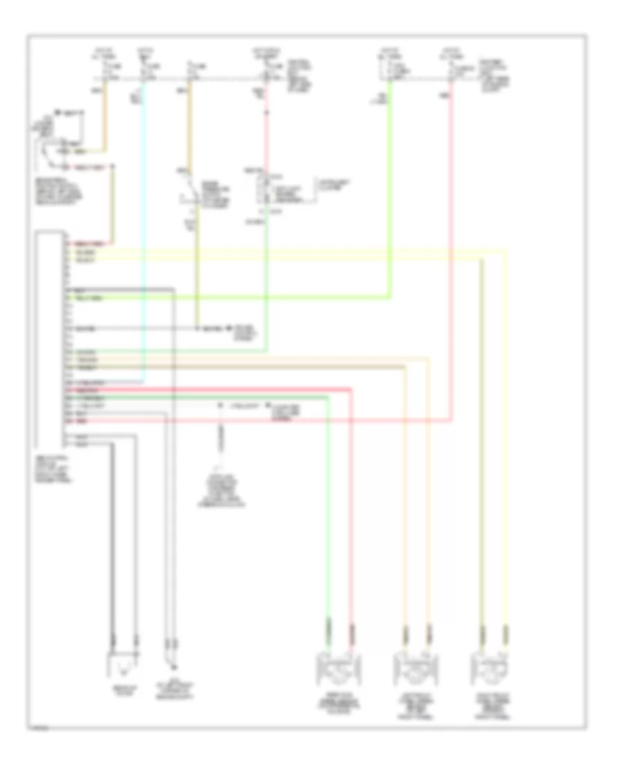
ANTI-LOCK BRAKES
Anti-lock Brakes Wiring Diagram for Mazda BSE 2003 4000
 https://portal-diagnostov.com/license.html
Automotive Electricians Portal FZCO
Automotive Electricians Portal FZCO
https://portal-diagnostov.com/license.html
https://portal-diagnostov.com/license.html
Automotive Electricians Portal FZCO
Automotive Electricians Portal FZCOList of elements for Anti-lock Brakes Wiring Diagram for Mazda BSE 2003 4000:
- Abs control module (4.0l: on left front inner fender panel)
- Abs pump motor
- Anti-lock brakes indicator
- Battery junction box (left rear of engine compt)
- Brake pedal position switch (behind left side of dash, on brake pedal support)
- Brake pressure switch (at master cylinder)
- C215
- C216
- Central junction box (behind left side of dash)
- Computer data lines system
- Cruise control system
- Data link connector (fastened to bottom of dash, near steering column)
- Fuse 10a
- Fuse 28 30a
- Fuse 2a
- Fuse 7.5a
- G10 (under driver's seat)
- G12 (at left front corner of engine compt)
- Hot at all times
- Hot in run
- Hot in run or start
- Instrument cluster
- Left front wheel speed sensor (at left front wheel)
- Maxi fuse 6 50a
- Nca
- Rear axle speed sensor (on differential housing)
- Red
- Red/pnk
- Right front wheel speed sensor (at right front wheel)
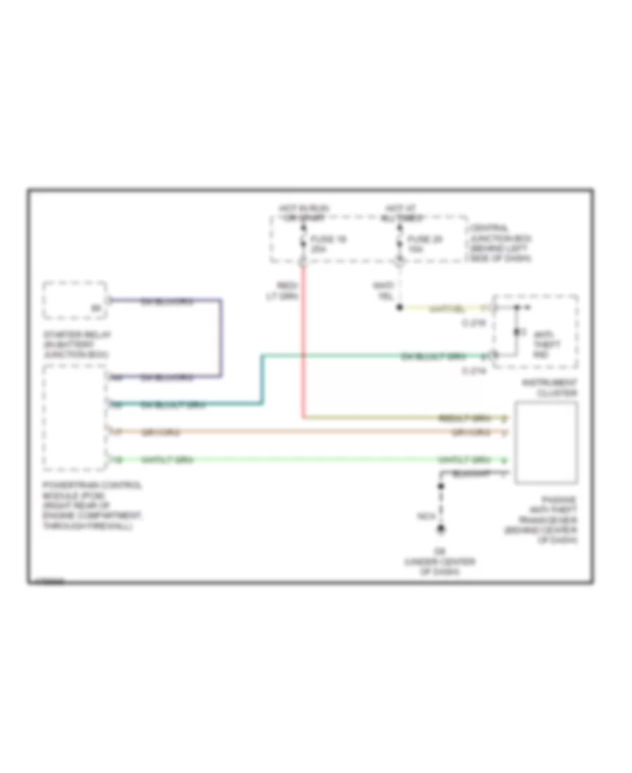
ANTI-THEFT
Passive Anti-theft Wiring Diagram for Mazda BSE 2003 4000
 https://portal-diagnostov.com/license.html
Automotive Electricians Portal FZCO
Automotive Electricians Portal FZCO
https://portal-diagnostov.com/license.html
https://portal-diagnostov.com/license.html
Automotive Electricians Portal FZCO
Automotive Electricians Portal FZCOList of elements for Passive Anti-theft Wiring Diagram for Mazda BSE 2003 4000:
- Anti- theft ind
- C-214
- C-216
- Central junction box (behind left side of dash)
- Fuse 19 25a
- Fuse 26 10a
- G8 (under center of dash)
- Hot at all times
- Hot in run or start
- Instrument cluster
- Nca
- Passive anti-theft transceiver (behind center of dash)
- Powertrain control module (pcm) (right rear of engine compartment, through firewall)
- Starter relay (in battery junction box)
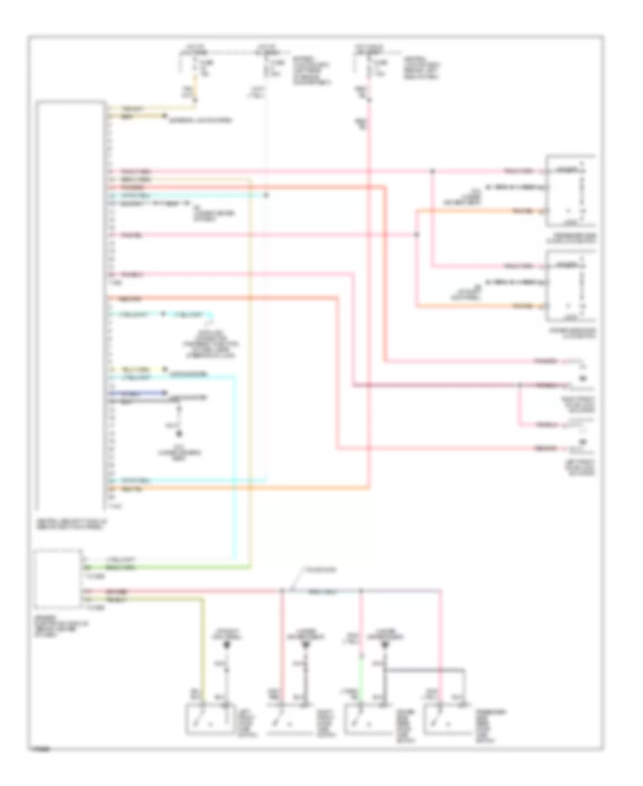
Power Door Locks Wiring Diagram for Mazda BSE 2003 4000
 https://portal-diagnostov.com/license.html
Automotive Electricians Portal FZCO
Automotive Electricians Portal FZCO
https://portal-diagnostov.com/license.html
https://portal-diagnostov.com/license.html
Automotive Electricians Portal FZCO
Automotive Electricians Portal FZCOList of elements for Power Door Locks Wiring Diagram for Mazda BSE 2003 4000:
- (at right kick panel) g9
- (under driver's seat) g10
- Battery junction box (left rear of engine compartment)
- Central junction box (behind left side of dash)
- Central security module (behind right kick panel)
- Data link connector (fastened to bottom of dash, near steering column)
- Driver side door lock switch
- Driver side rear door ajar switch
- Exterior lights system
- Four door
- Fuse 15a
- Fuse 20a
- Fuse 7.5a
- G10 (under driver's seat)
- G8 (under center of dash)
- G9 (at right kick panel)
- Generic electronic module (behind center of dash)
- Horns system
- Hot at all times
- Hot in run or start
- Left front door ajar switch
- Left front door lock actuator
- Lock
- Nca
- Passenger side door lock switch
- Passenger side rear door ajar switch
- Right front door ajar switch
- Right front door lock actuator
- T-2100b
- T-409
- T-410
- Unlock
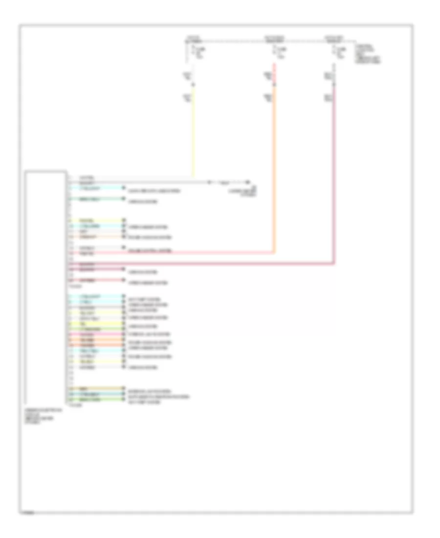
BODY CONTROL MODULES
Body Control Modules Wiring Diagram for Mazda BSE 2003 4000
 https://portal-diagnostov.com/license.html
Automotive Electricians Portal FZCO
Automotive Electricians Portal FZCO
https://portal-diagnostov.com/license.html
https://portal-diagnostov.com/license.html
Automotive Electricians Portal FZCO
Automotive Electricians Portal FZCOList of elements for Body Control Modules Wiring Diagram for Mazda BSE 2003 4000:
- Anti-theft system
- Central junction box (behind left side of dash)
- Computer data lines system
- Cruise control system
- Exterior lights system
- Fuse 10a
- Fuse 7.5a
- G8 (under center of dash)
- Generic electronic module (behind center of dash)
- Hot at all times
- Hot in acc or run
- Hot in run or start
- Interior lights system
- Nca
- Power windows system
- T-2100a
- T-2100b
- Tan/red
- Warning system
- Wiper/washer system
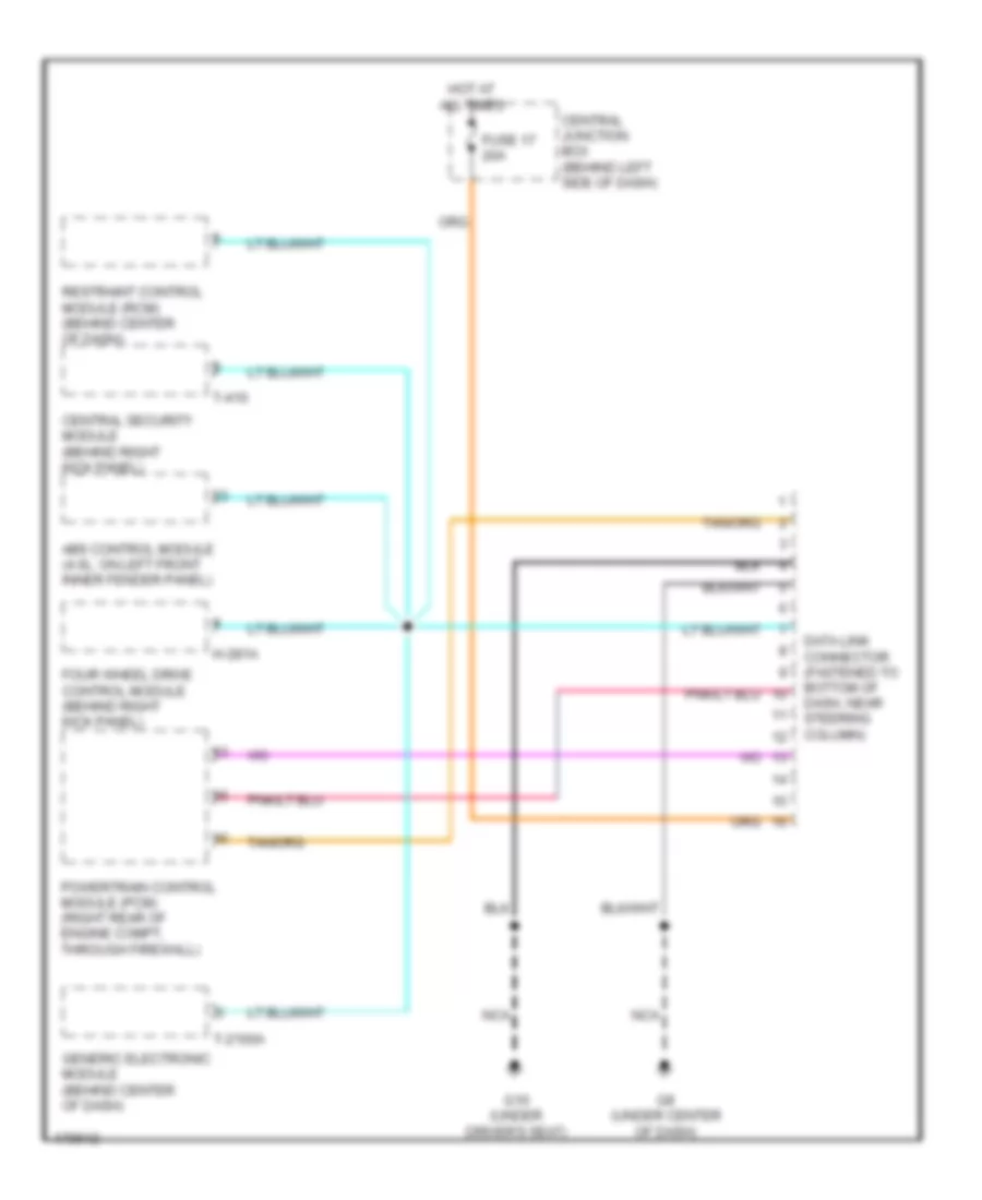
COMPUTER DATA LINES
Computer Data Lines Wiring Diagram for Mazda BSE 2003 4000
 https://portal-diagnostov.com/license.html
Automotive Electricians Portal FZCO
Automotive Electricians Portal FZCO
https://portal-diagnostov.com/license.html
https://portal-diagnostov.com/license.html
Automotive Electricians Portal FZCO
Automotive Electricians Portal FZCOList of elements for Computer Data Lines Wiring Diagram for Mazda BSE 2003 4000:
- Abs control module (4.0l: on left front inner fender panel)
- Central junction box (behind left side of dash)
- Central security module (behind right kick panel)
- Data link connector (fastened to bottom of dash, near steering column)
- Four wheel drive control module (behind right kick panel)
- Fuse 17 20a
- G10 (under driver's seat)
- G8 (under center of dash)
- Generic electronic module (behind center of dash)
- H-281a
- Hot at all times
- Nca
- Powertrain control module (pcm) (right rear of engine compt, through firewall)
- Restraint control module (rcm) (behind center of dash)
- T-2100a
- T-410
CRUISE CONTROL
Cruise Control Wiring Diagram for Mazda BSE 2003 4000
 https://portal-diagnostov.com/license.html
Automotive Electricians Portal FZCO
Automotive Electricians Portal FZCO
https://portal-diagnostov.com/license.html
https://portal-diagnostov.com/license.html
Automotive Electricians Portal FZCO
Automotive Electricians Portal FZCOList of elements for Cruise Control Wiring Diagram for Mazda BSE 2003 4000:
- 15a
- 7.5a
- A/t
- Abs control module (4.0l : on left front inner fender panel)
- Air bag sliding contact
- Battery junction box (left rear of engine compartment)
- Brake pedal position switch (behind left side of dash, on brake pedal support)
- Brake pressure switch (at master cylinder)
- C214
- C215
- Central junction box (behind left side of dash)
- Clutch pedal position switch (behind left side of dash, top of clutch pedal support)
- Coast
- Cruise control ind
- Engine controls system
- Exterior lights system
- Four wheel drive control module (behind right kick panel)
- Fuse 10
- Fuse 11
- Fuse 33
- Fuse 6
- Fuse 9
- G10 (under driver's seat)
- G5 (4.0l: at right rear corner of engine compt)
- G8 (under center of dash)
- Generic electronic module (behind center of dash)
- H281b
- Head
- Horn
- Horns system
- Hot at all times
- Hot in on or start
- Hot in run
- Instrument cluster
- Instrument panel dimming module (behind left side of dash)
- Interior lights system
- M/t
- Main light switch
- Nca
- Off
- Output shaft speed sensor (left side of transmission)
- Park
- Powertrain control module (pcm) (right rear of engine compartment, through firewall)
- Rest
- Resume
- Set/accelerate
- Speed contrl off
- Speed contrl on
- Speed control servo (in right rear of engine compart)
- Steering wheel/speed control switch
- T2100a
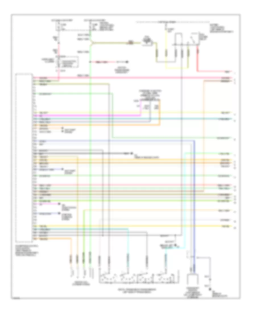
ENGINE PERFORMANCE
4.0L
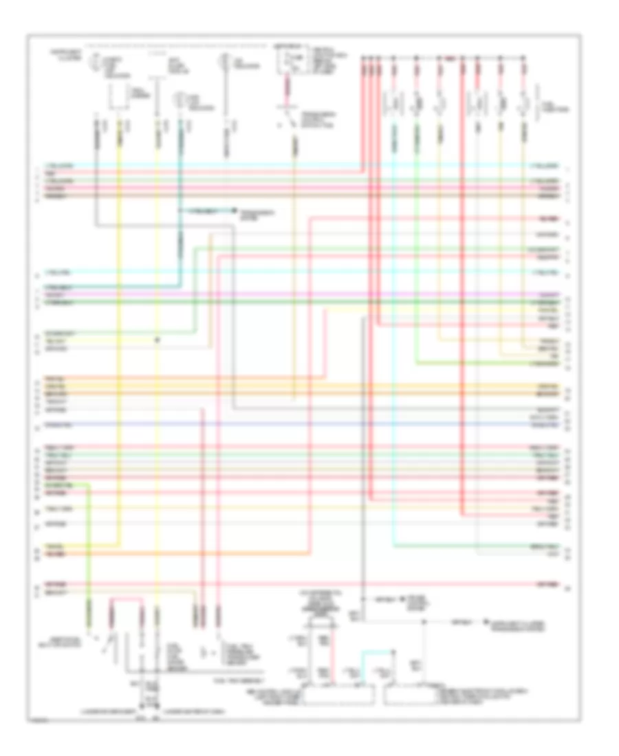
4.0L, Engine Performance Wiring Diagram (1 of 4) for Mazda BSE 2003 4000
 https://portal-diagnostov.com/license.html
Automotive Electricians Portal FZCO
Automotive Electricians Portal FZCO
https://portal-diagnostov.com/license.html
https://portal-diagnostov.com/license.html
Automotive Electricians Portal FZCO
Automotive Electricians Portal FZCOList of elements for 4.0L, Engine Performance Wiring Diagram (1 of 4) for Mazda BSE 2003 4000:
- (behind left headlight)
- (fastened to bottom of dash, near steering column) data link connector (dlc)
- Air conditioning system
- Anti-theft system
- Battery junction box (left rear of engine compartment)
- C209
- C215
- Central junction box (behind left side of dash)
- Crankshaft position (ckp) sensor (on lower front of engine)
- Digital transmission range sensor (left side of transmission)
- Fuse 25a
- Fuse 7 30a
- Fuse 7.5a
- G2 (rear of engine compt)
- Hot at all times
- Hot in run or start
- Ignition coil (on rear of eng)
- Ignition transformer capacitor 1
- Instrument cluster
- Malfunction indicator lamp (mil)
- Pcm power diode
- Pcm power relay
- Powertrain control module (pcm) (right rear of engine compartment, through firewall)
- Red
- Starting/ charging system
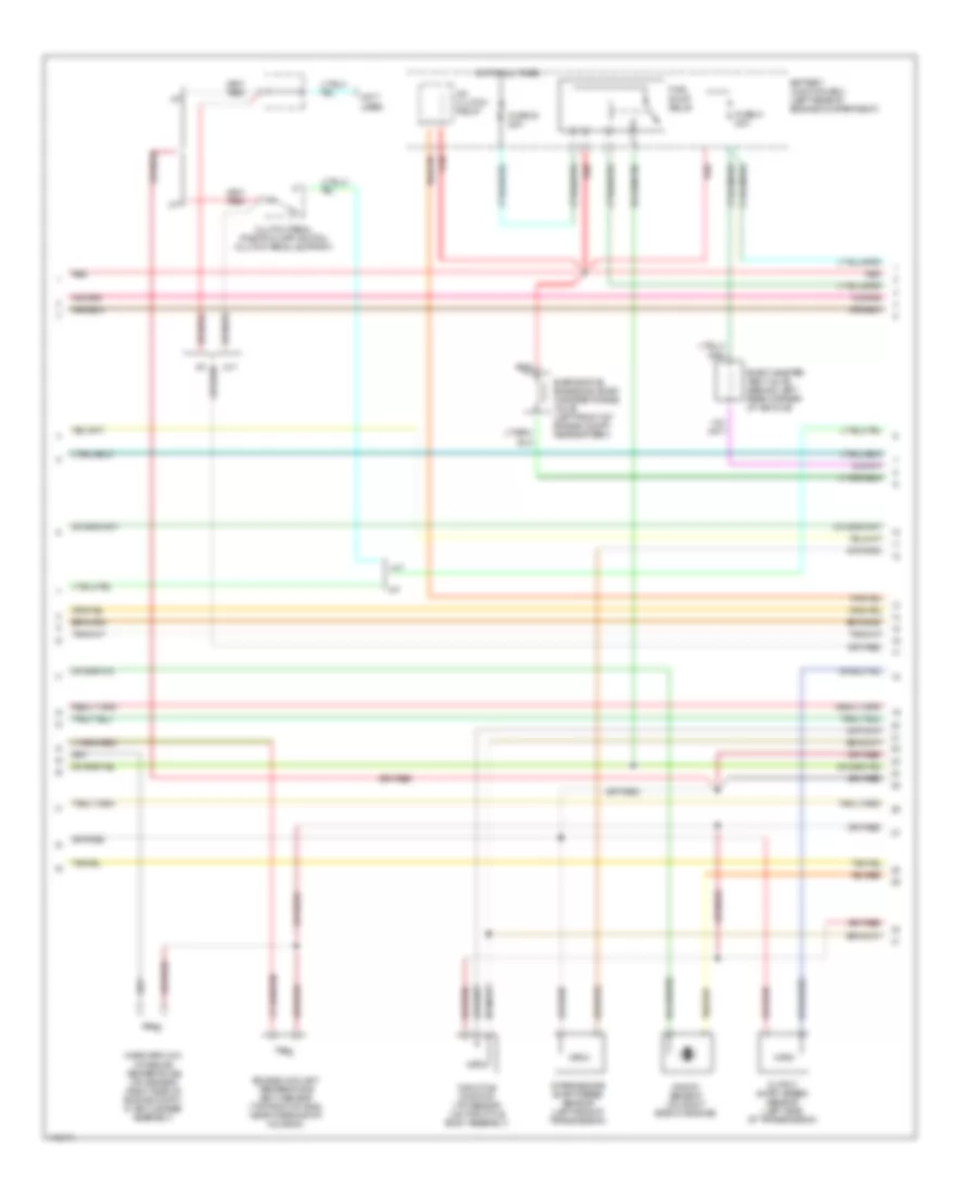
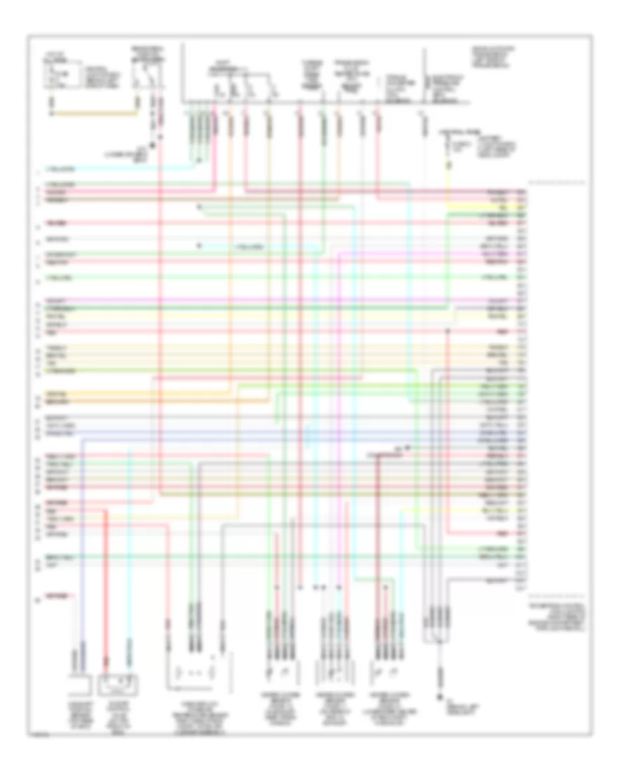
4.0L, Engine Performance Wiring Diagram (2 of 4) for Mazda BSE 2003 4000
 https://portal-diagnostov.com/license.html
Automotive Electricians Portal FZCO
Automotive Electricians Portal FZCO
https://portal-diagnostov.com/license.html
https://portal-diagnostov.com/license.html
Automotive Electricians Portal FZCO
Automotive Electricians Portal FZCOList of elements for 4.0L, Engine Performance Wiring Diagram (2 of 4) for Mazda BSE 2003 4000:
- (not used)
- A/c clutch relay
- A/t
- A/t
- Battery junction box (left rear of engine compartment)
- Clutch pedal position (cpp) switch (clutch pedal support)
- Engine coolant temperature (ect) sensor (top right of eng, near thermostat housing)
- Evap canister vent valve (behind left rear corner of vehicle)
- Evaporative emissions (evap) canister purge valve (left front of engine compt, near battery)
- Fuel pump relay
- Fuse 23 20a
- Fuse 41 20a
- Hot at all times
- Intermediate shaft speed sensor (left side of transmission)
- Knock sensor (on right side of engine)
- M/t
- M/t
- Mass airflow/ intake air temperature (iat) sensor (right side of engine compt, in air cleaner assembly)
- Output shaft speed sensor (left side of transmission)
- Red
- Throttle position (tp) sensor (on throttle body assembly)
4.0L, Engine Performance Wiring Diagram (3 of 4) for Mazda BSE 2003 4000
 https://portal-diagnostov.com/license.html
Automotive Electricians Portal FZCO
Automotive Electricians Portal FZCO
https://portal-diagnostov.com/license.html
https://portal-diagnostov.com/license.html
Automotive Electricians Portal FZCO
Automotive Electricians Portal FZCOList of elements for 4.0L, Engine Performance Wiring Diagram (3 of 4) for Mazda BSE 2003 4000:
- (on differential housing) rear axle speed sensor
- (under center of dash)
- (under driver's seat)
- 4wd low indicator
- Abs control module (left front inner fender panel)
- Anti- slosh module
- C214
- C215
- Central junction box (behind left side of dash)
- Check fuel cap indicator
- Cruise control system
- Fuel injectors
- Fuel pump/ fuel gauge sender
- Fuel tank assembly
- Fuel tank pressure transducer sensor
- Fuse 15a
- G10
- Generic electronic module (gem)/ central timer module (ctm) (center of dash)
- Hot in run
- Inertia fuel shut-off switch
- Instrument cluster
- Instrument cluster, transmission system
- O/d indicator
- Red
- Red/ pnk
- Red/pnk
- T2100a
- Tach- ometer
- Tan
- Transmission control switch (tcs)
- Transmission system
4.0L, Engine Performance Wiring Diagram (4 of 4) for Mazda BSE 2003 4000
 https://portal-diagnostov.com/license.html
Automotive Electricians Portal FZCO
Automotive Electricians Portal FZCO
https://portal-diagnostov.com/license.html
https://portal-diagnostov.com/license.html
Automotive Electricians Portal FZCO
Automotive Electricians Portal FZCOList of elements for 4.0L, Engine Performance Wiring Diagram (4 of 4) for Mazda BSE 2003 4000:
- 4r44e automatic transmission (left side of transmission)
- Air conditioning
- Battery junction box (left rear of eng compt)
- Brake pedal position switch (bpp)
- Camshaft position sensor (top rear of eng)
- Central junction box (behind left side of dash)
- Electronic pressure control (epc) solenoid
- Fuse 21 10a
- Fuse 7.5a
- G1 (behind left headlight)
- G10 (under driver's seat)
- Heated oxygen sensor (ho2s) 11 (on rear of eng, in exhaust)
- Heated oxygen sensor (ho2s) 12 (in exhaust, near trans- mission)
- Heated oxygen sensor (ho2s) 21 (lower rear center of eng compt, in exhaust)
- Hot at all times
- Idle air control valve (on top front of eng)
- Mass airflow/ intake air temperature sensor (right side of eng compt, within air cleaner assembly)
- Nca
- Powertrain control module (pcm) (right rear of engine compartment, through firewall)
- Red
- Red/pnk
- Shift solenoids
- Tan
- Torque converter clutch (tcc) solenoid
- Transmission fluid temperature (tft) sensor
- Turbine shaft speed (tss) sensor
EXTERIOR LIGHTS
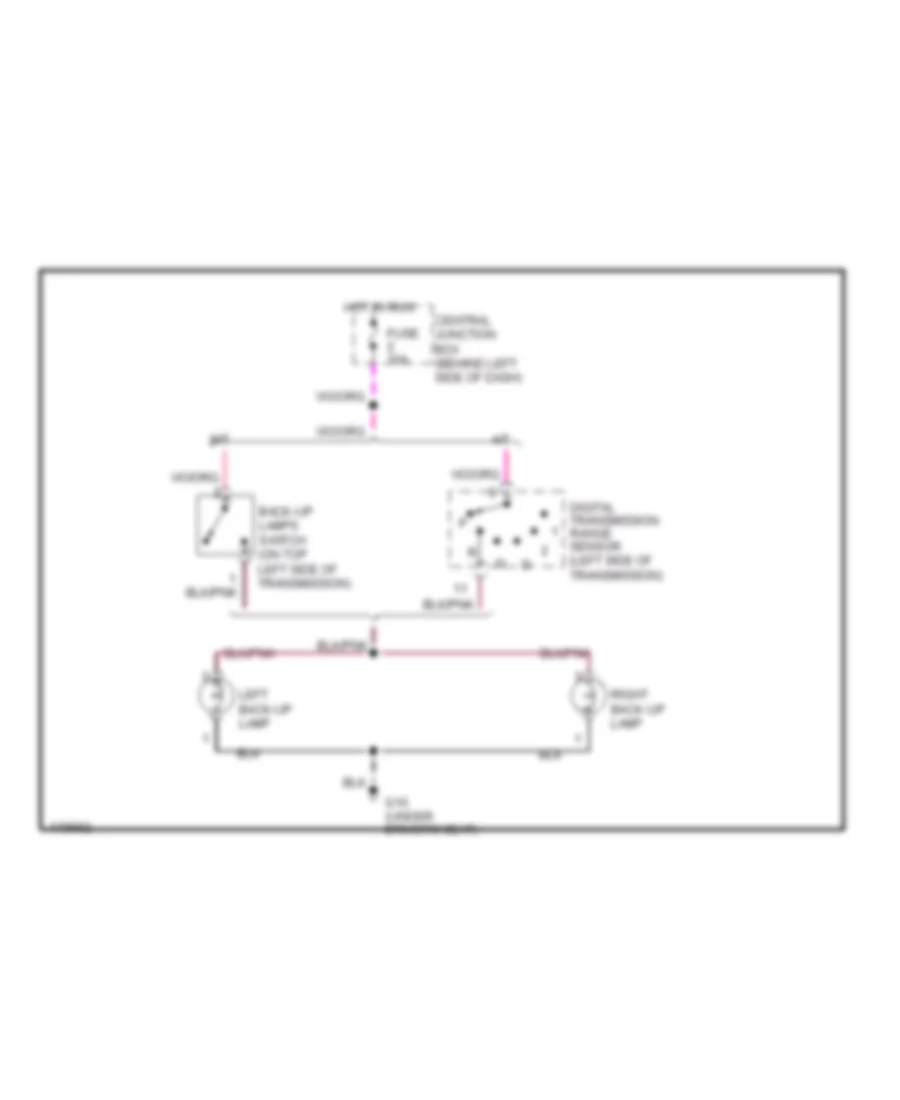
Back-up Lamps Wiring Diagram for Mazda BSE 2003 4000
 https://portal-diagnostov.com/license.html
Automotive Electricians Portal FZCO
Automotive Electricians Portal FZCO
https://portal-diagnostov.com/license.html
https://portal-diagnostov.com/license.html
Automotive Electricians Portal FZCO
Automotive Electricians Portal FZCOList of elements for Back-up Lamps Wiring Diagram for Mazda BSE 2003 4000:
- A/t
- Back-up lamps switch (on top left side of transmission)
- Central junction box (behind left side of dash)
- Digital transmission range sensor (left side of transmission)
- Fuse 10a
- G10 (under driver's seat)
- Hot in run
- Left back-up lamp
- M/t
- Right back-up lamp
Exterior Lamps Wiring Diagram (1 of 2) for Mazda BSE 2003 4000
 https://portal-diagnostov.com/license.html
Automotive Electricians Portal FZCO
Automotive Electricians Portal FZCO
https://portal-diagnostov.com/license.html
https://portal-diagnostov.com/license.html
Automotive Electricians Portal FZCO
Automotive Electricians Portal FZCOList of elements for Exterior Lamps Wiring Diagram (1 of 2) for Mazda BSE 2003 4000:
- (behind dash, right of steering column) auxiliary relay box 1
- (not used)
- (under driver's seat) g10
- Brake pedal position switch (behind left side of dash, on brake pedal support)
- C214
- C215
- Cargo lamp/ high mount stop light assembly
- Central junction box (behind left side of dash)
- Fuse 15a
- Fuse 20a
- Fuse 7.5a
- G10 (under driver's seat)
- Hazard
- High mounted stoplamp
- Hot at all times
- Hot in run
- Indicator flasher relay
- Instrument cluster
- Left license lamp
- Left rear park/stop lamp
- Left turn
- Left turn indicator
- Multi-function switch
- Normal
- Right license plate lamp
- Right rear park/stop lamp
- Right turn
- Right turn indicator
- Trailer tow circuit
- X253
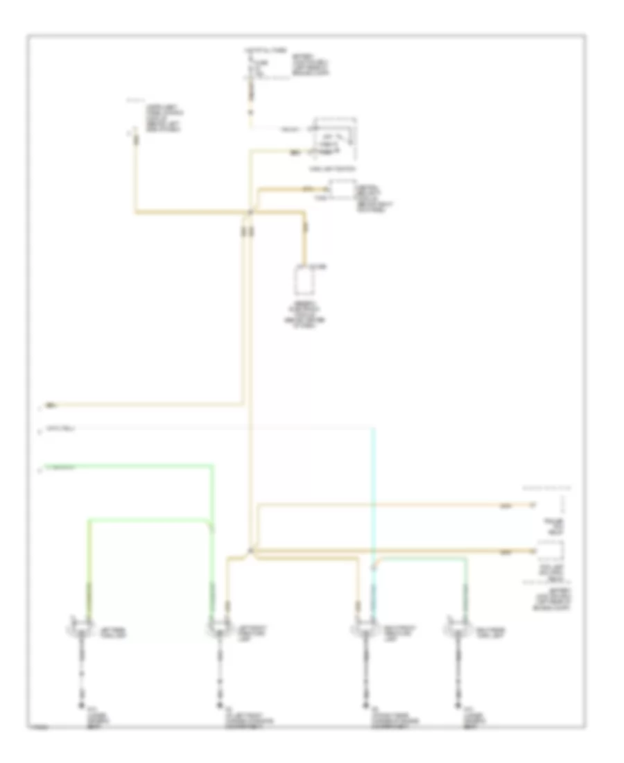
Exterior Lamps Wiring Diagram (2 of 2) for Mazda BSE 2003 4000
 https://portal-diagnostov.com/license.html
Automotive Electricians Portal FZCO
Automotive Electricians Portal FZCO
https://portal-diagnostov.com/license.html
https://portal-diagnostov.com/license.html
Automotive Electricians Portal FZCO
Automotive Electricians Portal FZCOList of elements for Exterior Lamps Wiring Diagram (2 of 2) for Mazda BSE 2003 4000:
- Battery junction box (left rear of engine compt)
- C2100b
- Central security module (behind right kick panel)
- Fog lamp isolation relay
- Fuse 15a
- G10 (under driver's seat)
- G3 (at left front corner of engine compartment)
- G5 (at right rear corner of engine compartment)
- Generic electronic module (behind center of dash)
- Head
- Hot at all times
- Instrument panel dimming module (behind left side of dash)
- Left front park/turn lamp
- Left rear turn lamp
- Main light switch
- Off
- Park
- Right front park/turn lamp
- Right rear turn lamp
- T-409
- Trailer tow relay
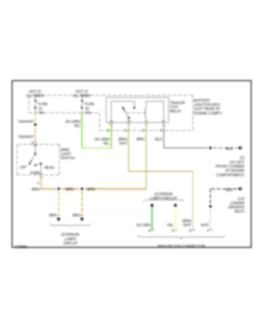
Trailer Tow Wiring Diagram for Mazda BSE 2003 4000
 https://portal-diagnostov.com/license.html
Automotive Electricians Portal FZCO
Automotive Electricians Portal FZCO
https://portal-diagnostov.com/license.html
https://portal-diagnostov.com/license.html
Automotive Electricians Portal FZCO
Automotive Electricians Portal FZCOList of elements for Trailer Tow Wiring Diagram for Mazda BSE 2003 4000:
- Battery junction box (left rear of engine compt)
- Exterior lamps circuit
- Fuse 15a
- G10 (under driver's seat)
- G3 (at left front corner of engine compartment)
- Head
- Hot at all times
- Main light switch
- Off
- Park
- Trailer tow connector
- Trailer tow relay
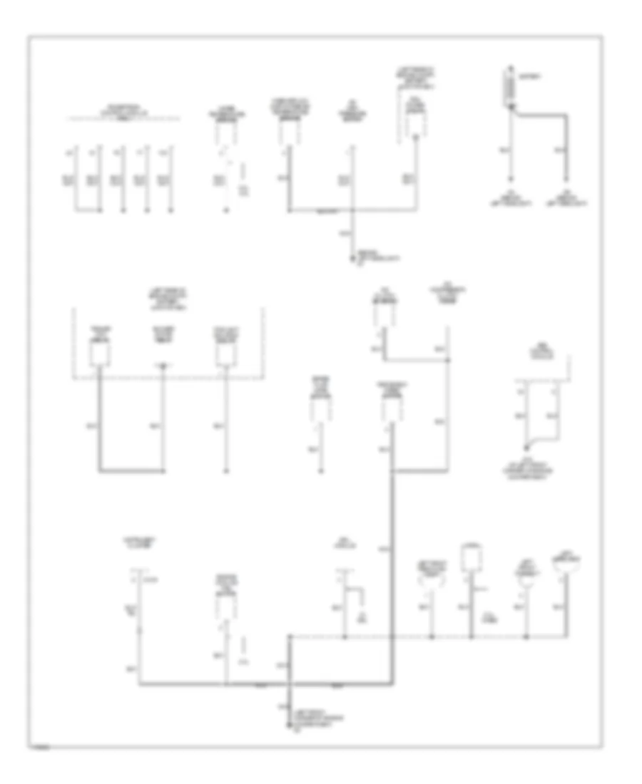
GROUND DISTRIBUTION
Ground Distribution Wiring Diagram (1 of 4) for Mazda BSE 2003 4000
 https://portal-diagnostov.com/license.html
Automotive Electricians Portal FZCO
Automotive Electricians Portal FZCO
https://portal-diagnostov.com/license.html
https://portal-diagnostov.com/license.html
Automotive Electricians Portal FZCO
Automotive Electricians Portal FZCOList of elements for Ground Distribution Wiring Diagram (1 of 4) for Mazda BSE 2003 4000:
- (behind left headlight) g1
- (left front corner of engine compartment) g3
- (left rear of engine compt) battery junction box
- 2.3l
- 2.3l, 4.0l
- 2.3l, w/abs
- A/c clutch solenoid
- A/c compressor clutch diode
- A/c high pressure switch
- Abs control module
- Battery
- Blower motor relay
- Brake fluid level switch
- C-216
- Drl module
- Engine cooling fan motor
- Foglight isolation relay
- G12 (at left front corner of engine compartment)
- G4 (behind left headlight)
- G6 (behind left headlight)
- Horn
- Instrument cluster
- Left front foglight
- Left front park/turn light
- Left headlight
- Mass airflow (maf)/intake air temperature sensor
- Nca
- Pcm power relay
- Powertrain control module (pcm)
- Trailer tow relay
- W/ drl
- Water temperature sender
- Windshield wiper motor
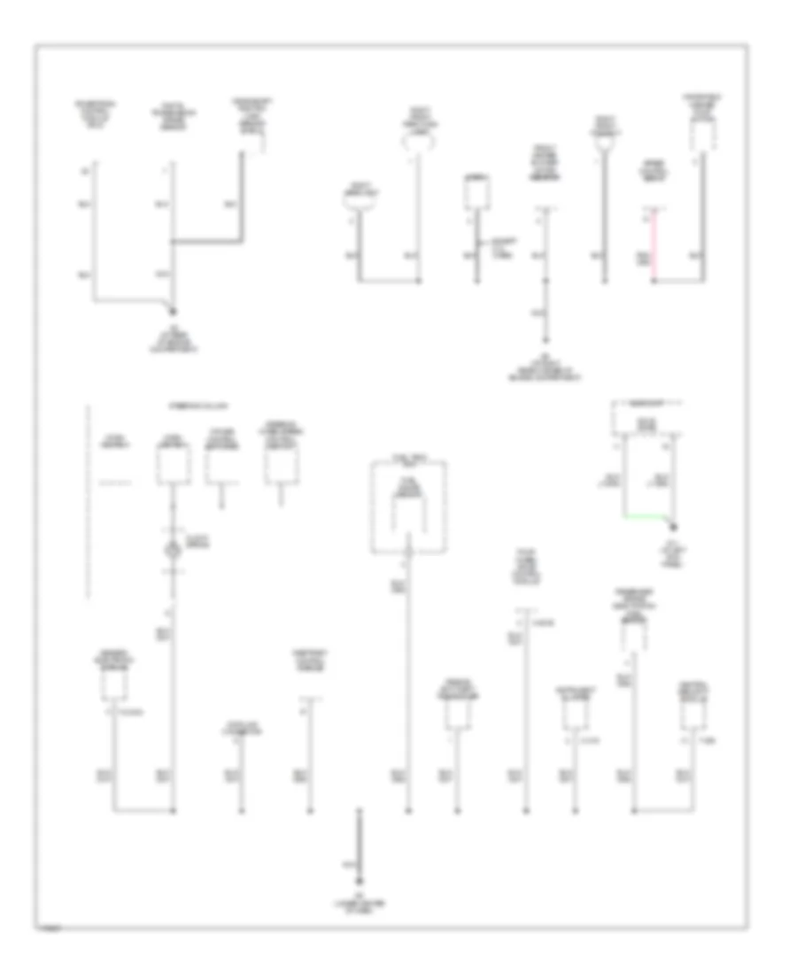
Ground Distribution Wiring Diagram (2 of 4) for Mazda BSE 2003 4000
 https://portal-diagnostov.com/license.html
Automotive Electricians Portal FZCO
Automotive Electricians Portal FZCO
https://portal-diagnostov.com/license.html
https://portal-diagnostov.com/license.html
Automotive Electricians Portal FZCO
Automotive Electricians Portal FZCOList of elements for Ground Distribution Wiring Diagram (2 of 4) for Mazda BSE 2003 4000:
- Audio unit
- C-215
- Central security module
- Clock spring
- Crankshaft position (ckp) sensor shield
- Cruise control switches
- Data link connector
- Digital transmission range sensor
- Except 2.3l w/abs
- Four- wheel drive control module
- Front heater blower motor resistor
- Fuel gauge sensor
- Fuel tank unit
- G11 (at left kick panel)
- G2 (at rear of engine compartment)
- G5 (at right rear corner of engine compartment)
- G8 (under center of dash)
- Generic electronic module
- H-281b
- Horn
- Horn switch
- Instrument cluster
- Nca
- Passenger air bag deactivation (pad) switch
- Passive anti-theft transceiver
- Powertrain control module (pcm)
- Restraint control module
- Right front foglight
- Right front park/turn light
- Right headlight
- Solid state
- Speed control servo
- Steering column
- Steering wheel/speed control switch
- T-2100a
- T-409
- Windshield washer pump motor
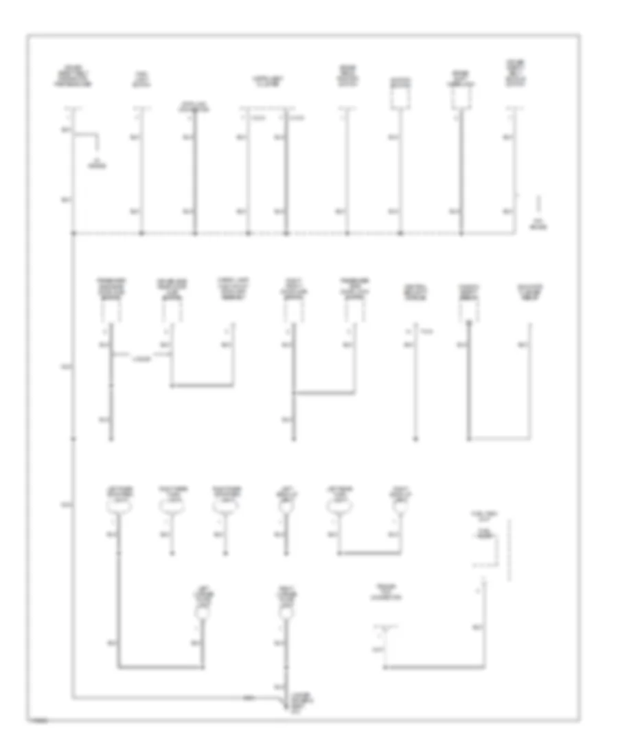
Ground Distribution Wiring Diagram (3 of 4) for Mazda BSE 2003 4000
 https://portal-diagnostov.com/license.html
Automotive Electricians Portal FZCO
Automotive Electricians Portal FZCO
https://portal-diagnostov.com/license.html
https://portal-diagnostov.com/license.html
Automotive Electricians Portal FZCO
Automotive Electricians Portal FZCOList of elements for Ground Distribution Wiring Diagram (3 of 4) for Mazda BSE 2003 4000:
- (under driver's seat) g10
- 4 door
- Brake pedal position switch
- Brake shift interlock
- C-214
- C-215
- Cargo lamp/ high mount stoplamp assembly
- Central security module
- Data link connector
- Driver safety belt buckle switch
- Driver safety belt retractor pretensioner
- Driver side rear door ajar switch
- Fuel pump
- Fuel tank unit
- Ignition switch
- Indicator flasher relay
- Instrument cluster
- Left back-up light
- Left license plate light
- Left rear stop/park light
- Left rear turn light
- Main light switch
- Nca
- Passenger side door lock switch
- Passenger side rear door ajar switch
- Right back-up light
- Right front door ajar switch
- Right license plate light
- Right rear stop/park light
- Right rear turn light
- T-410
- Trailer tow connector
- W/ air bag
- W/o air bag
- Window safety relay
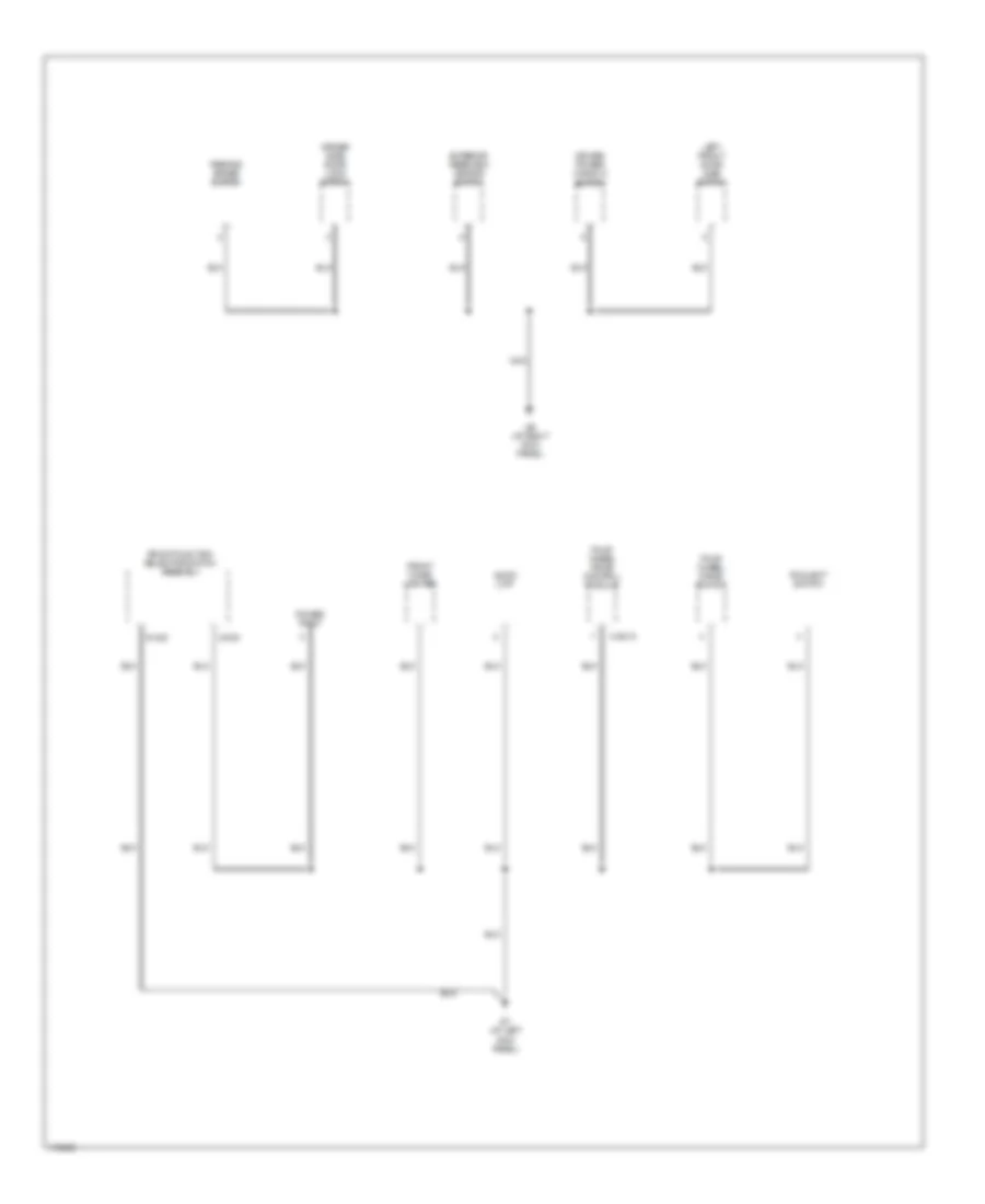
Ground Distribution Wiring Diagram (4 of 4) for Mazda BSE 2003 4000
 https://portal-diagnostov.com/license.html
Automotive Electricians Portal FZCO
Automotive Electricians Portal FZCO
https://portal-diagnostov.com/license.html
https://portal-diagnostov.com/license.html
Automotive Electricians Portal FZCO
Automotive Electricians Portal FZCOList of elements for Ground Distribution Wiring Diagram (4 of 4) for Mazda BSE 2003 4000:
- Audio unit
- Driver power window switch
- Driver side door lock switch
- Exterior rearview mirror switch
- Foglight switch
- Four wheel drive control module
- Four wheel drive switch
- Front cigar lighter
- Front function selector switch assembly
- G-232
- G-233
- G7 (at left kick panel)
- G9 (at right kick panel)
- H-281a
- Left front door ajar switch
- Nca
- Parking brake switch
- Power point
HEADLIGHTS
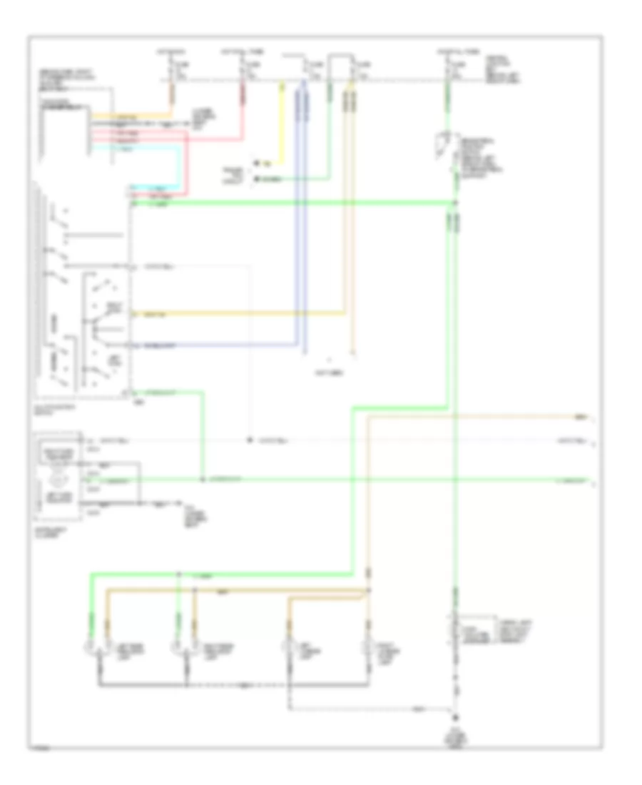
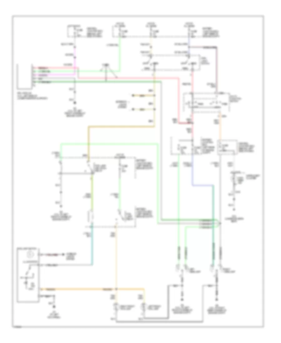
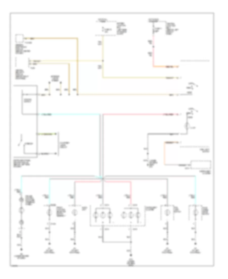
Headlights Wiring Diagram for Mazda BSE 2003 4000
 https://portal-diagnostov.com/license.html
Automotive Electricians Portal FZCO
Automotive Electricians Portal FZCO
https://portal-diagnostov.com/license.html
https://portal-diagnostov.com/license.html
Automotive Electricians Portal FZCO
Automotive Electricians Portal FZCOList of elements for Headlights Wiring Diagram for Mazda BSE 2003 4000:
- 10a
- 15a
- 20a
- 30a
- Battery junction box (left rear of engine compt)
- C215
- Central junction box (behind left side of dash)
- Drl module (4.0l: left side of lower radiator support)
- Exterior lights system
- Fog lamp isolation relay
- Fog lamp relay
- Fog lamp switch
- Fuse
- Fuse 10a
- Fuse 15a
- Fuse 20a
- G10 (under driver's seat)
- G3 (4.0l: at left front corner of engine compt)
- G5 (4.0l: at right rear corner of engine compt)
- G7 (at left kick panel)
- Head
- High beam ind
- Hot at all times
- Hot in run
- Illumination
- Instrument cluster
- Interior lights system
- Left front fog lamp
- Left headlamp
- Low
- Main light switch
- Multi- function switch
- Nca
- Off
- On ind
- Park
- Pass
- Pass low
- Right front fog lamp
- Right headlamp
- W/ drl
- X254
HORN
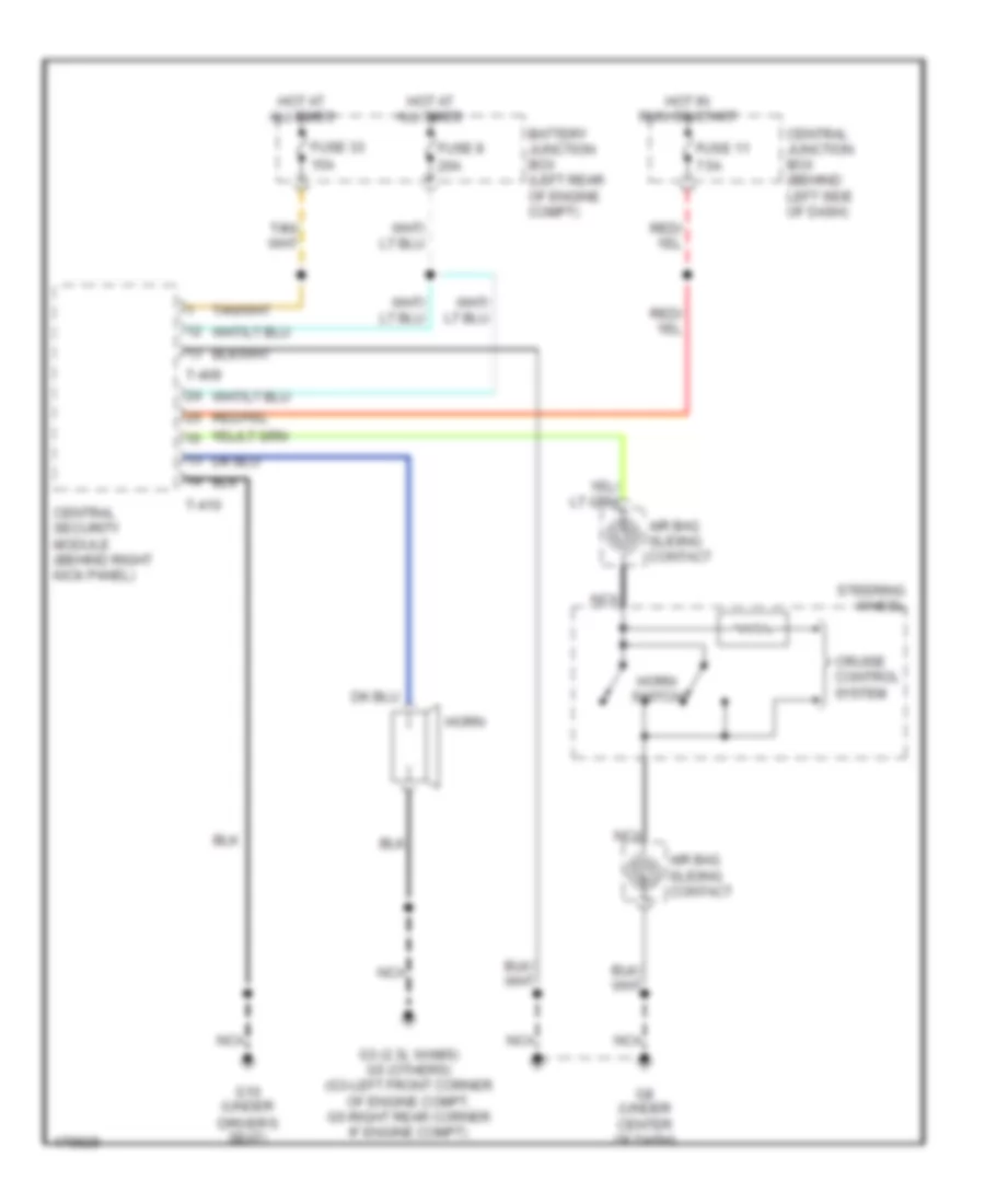
Horn Wiring Diagram, with Power Equipment for Mazda BSE 2003 4000
 https://portal-diagnostov.com/license.html
Automotive Electricians Portal FZCO
Automotive Electricians Portal FZCO
https://portal-diagnostov.com/license.html
https://portal-diagnostov.com/license.html
Automotive Electricians Portal FZCO
Automotive Electricians Portal FZCOList of elements for Horn Wiring Diagram, with Power Equipment for Mazda BSE 2003 4000:
- 15a
- 20a
- 7.5a
- Air bag sliding contact
- Battery junction box (left rear of engine compt)
- Central junction box (behind left side of dash)
- Central security module (behind right kick panel)
- Cruise control system
- Driver's seat)
- Fuse 11
- Fuse 33
- Fuse 8
- G10 (under
- G3 (2.3l w/abs) g5 (others) (g3-left front corner of engine compt, g5-right rear corner if engine compt)
- G8 (under center of dash)
- Horn
- Horn switch
- Hot at all times
- Hot in run or start
- Nca
- Steering wheel
- T-409
- T-410
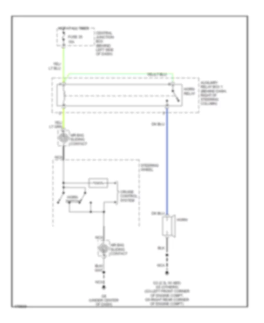
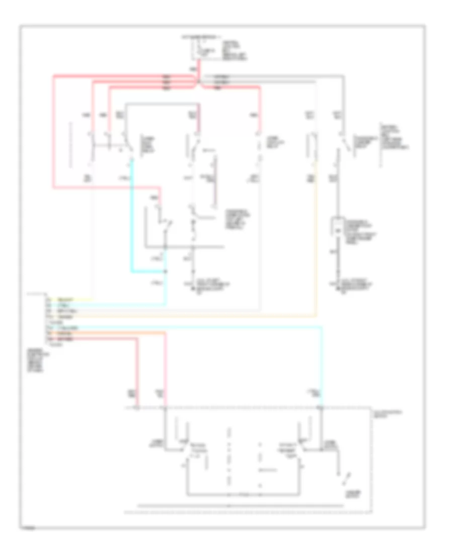
Horn Wiring Diagram, without Power Equipment for Mazda BSE 2003 4000
 https://portal-diagnostov.com/license.html
Automotive Electricians Portal FZCO
Automotive Electricians Portal FZCO
https://portal-diagnostov.com/license.html
https://portal-diagnostov.com/license.html
Automotive Electricians Portal FZCO
Automotive Electricians Portal FZCOList of elements for Horn Wiring Diagram, without Power Equipment for Mazda BSE 2003 4000:
- 15a
- Air bag sliding contact
- Auxiliary relay box 1 (behind dash, right of steering column)
- Central junction box (behind left side of dash)
- Cruise control system
- Fuse 35
- G3 (2.3l w/ abs) g5 (others) (g3-left front corner of engine compt, g5-right rear corner of engine compt)
- G8 (under center of dash)
- Horn
- Horn relay
- Horn switch
- Hot at all times
- Nca
- Steering wheel
INSTRUMENT CLUSTER
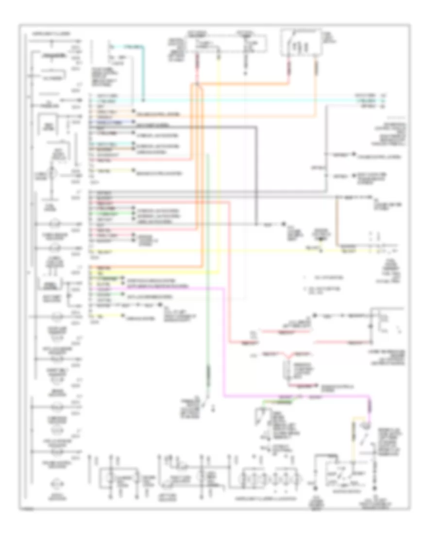
Instrument Cluster Wiring Diagram for Mazda BSE 2003 4000
 https://portal-diagnostov.com/license.html
Automotive Electricians Portal FZCO
Automotive Electricians Portal FZCO
https://portal-diagnostov.com/license.html
https://portal-diagnostov.com/license.html
Automotive Electricians Portal FZCO
Automotive Electricians Portal FZCOList of elements for Instrument Cluster Wiring Diagram for Mazda BSE 2003 4000:
- (at right kick panel) g9
- 2.3l
- 2.3l, 4.0l
- 2.3l, 4.ol
- 3.0l
- 3.0l w/ flex fuel
- 3.0l w/o flex fuel
- 3.0l, 4.0l
- 4wd hi indicator
- 4wd low range indicator
- Acc
- Air bag indi- cator
- Anti- slosh module
- Anti-lock brake indicator
- Anti-lock brakes system
- Anti-theft indicator
- Anti-theft system
- Body computer, transmissions systems
- Brake fluid level switch (left rear of engine compt, on brake fluid reservoir)
- Brake indicator
- C214
- C215
- C216
- Central junction box (behind left side of dash)
- Charge indi- cator
- Check engine indicator
- Check fuel cap indicator
- Check gauge
- Cruise control indicator
- Cruise control system
- Door ajar indicator
- Engine controls system
- Exterior lights system
- Four wheel drive control module (behind right kick panel)
- Fuel gauge
- Fuel gauge sensor
- Fuel tank unit (in fuel tank)
- Fuse 10a
- Fuse 11 7.5a
- G1 (4.0l: behind left headlight)
- G10 (under driver's seat)
- G3 (4.0l: at left front corner of engine compt)
- G8 (under center of dash)
- H-281b
- Head
- Headlights system
- High beam indi- cator
- Hot at all times
- Hot in run or start
- Ignition switch
- Instrument cluster
- Instrument cluster illumination
- Interior lights system
- Left turn indicator
- Lock
- Main light switch
- Nca
- Off
- Oil pressure
- Oil pressure switch (on lower left front of engine)
- Overdrive indicator
- Park
- Park brake switch (behind left side of dash, on park brake assembly)
- Powertrain control module (pcm) (right rear of engine compt, through firewall)
- Resistor (in battery junction box)
- Right turn indicator
- Run
- Safety belt indicator
- Speed- ometer
- Start
- Starting/charging system
- Tachometer
- Temp meter
- Voltmeter
- Warning system
- Water temperature sender (on top front center of engine)
INTERIOR LIGHTS
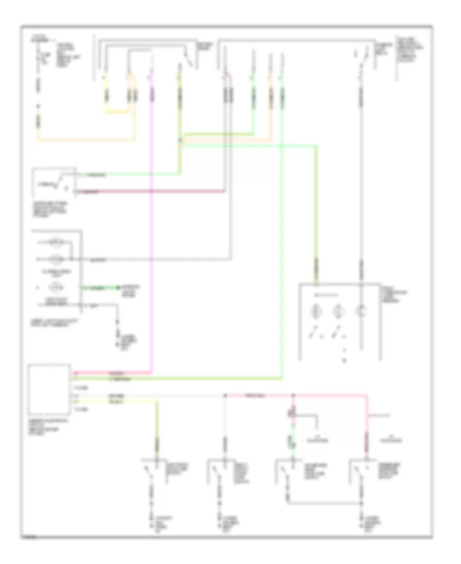
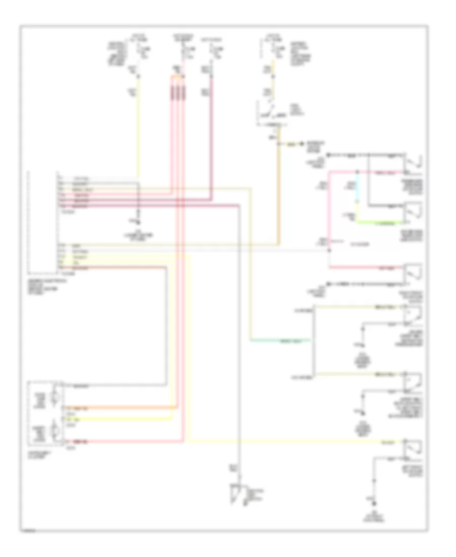
Courtesy Lamps Wiring Diagram for Mazda BSE 2003 4000
 https://portal-diagnostov.com/license.html
Automotive Electricians Portal FZCO
Automotive Electricians Portal FZCO
https://portal-diagnostov.com/license.html
https://portal-diagnostov.com/license.html
Automotive Electricians Portal FZCO
Automotive Electricians Portal FZCOList of elements for Courtesy Lamps Wiring Diagram for Mazda BSE 2003 4000:
- (at right kick panel) g9
- (under driver's seat) g10
- Auxiliary relay box 1 (behind dash, right of steering column)
- Battery saver
- Cargo light/ high mount stop light assembly
- Central junction box (behind left side of dash)
- Driver side rear door ajar switch
- Exterior lights system
- Front interior/map lamps assembly
- Fuse 10a
- Generic electronic module (behind center of dash)
- High mount stop light
- Hot at all times
- Instrument panel dimming module (behind left side of dash)
- Interior
- Interior lamp relay
- Left front door ajar switch
- Nca
- Outside cargo light
- Passenger side rear door ajar switch
- Right front door ajar switch
- T-2100b
- W/ four door
Instrument Illumination Wiring Diagram for Mazda BSE 2003 4000
 https://portal-diagnostov.com/license.html
Automotive Electricians Portal FZCO
Automotive Electricians Portal FZCO
https://portal-diagnostov.com/license.html
https://portal-diagnostov.com/license.html
Automotive Electricians Portal FZCO
Automotive Electricians Portal FZCOList of elements for Instrument Illumination Wiring Diagram for Mazda BSE 2003 4000:
- (under driver's seat) g10
- Audio unit
- Battery junction box (left rear of engine compt)
- C214
- C215
- Central junction box (behind left side of dash)
- Central security module (behind right kick panel)
- Courtesy lamps circuit
- Cruise control switches (steering wheel)
- Dimming switch
- Exterior lights system
- Fog lamp switch
- Four wheel drive switch
- Front function selector switch assembly
- Fuse 11 7.5a
- Fuse 33 15a
- G-233
- G10 (under driver's seat)
- G7 (at left kick panel)
- G8 (under center of dash)
- Generic electronic module (behind center of dash)
- Head
- Hot at all times
- Hot in run or start
- Illum
- Instrument cluster
- Instrument panel dimming module (behind left side of dash)
- Interior
- Main light switch
- Nca
- Off
- Park
- T-2100b
- T-409
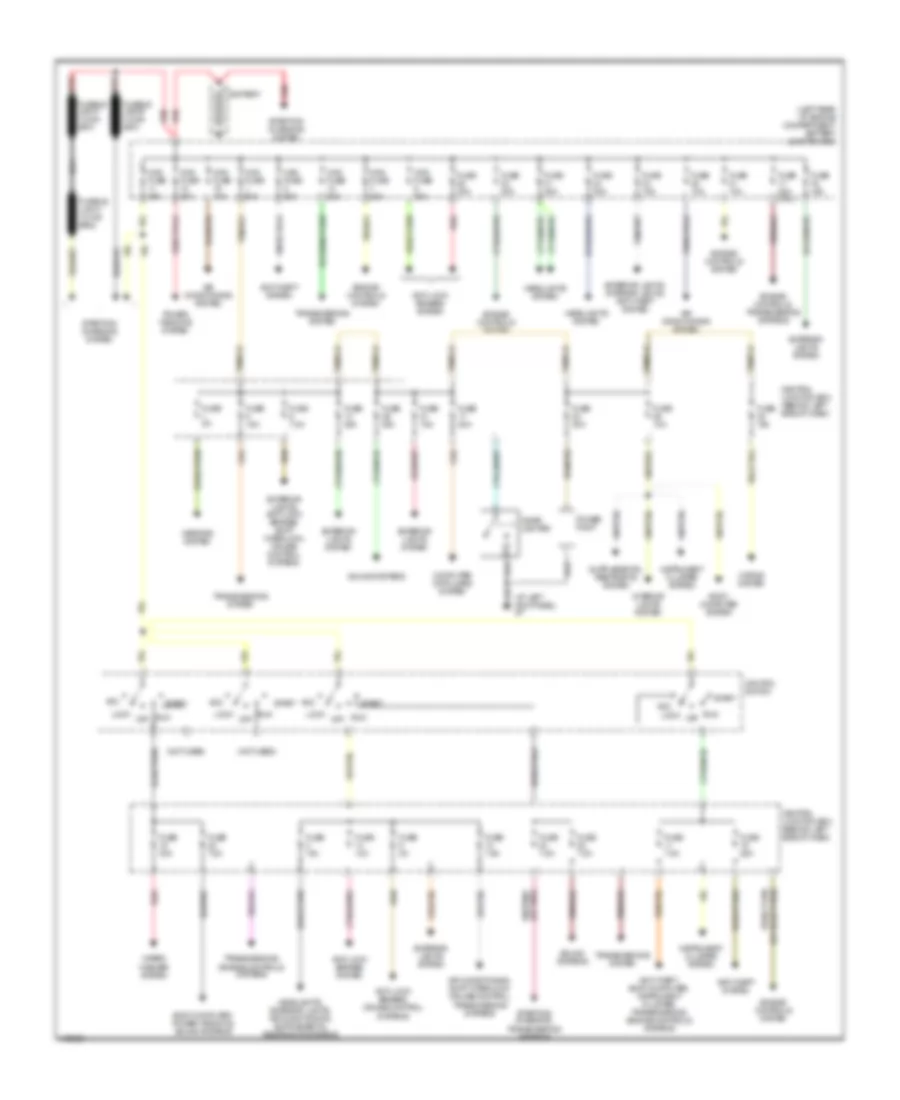
POWER DISTRIBUTION
Power Distribution Wiring Diagram for Mazda BSE 2003 4000
 https://portal-diagnostov.com/license.html
Automotive Electricians Portal FZCO
Automotive Electricians Portal FZCO
https://portal-diagnostov.com/license.html
https://portal-diagnostov.com/license.html
Automotive Electricians Portal FZCO
Automotive Electricians Portal FZCOList of elements for Power Distribution Wiring Diagram for Mazda BSE 2003 4000:
- (at left kick panel) g7
- (left rear of engine compartment) battery junction box
- (not used)
- Acc
- Air conditioning system
- Air conditioning, shift interlock, cruise control, transmissions systems
- Anti-lock brakes system
- Anti-lock brakes, cruise control systems
- Anti-theft system
- Anti-theft, body computer, instrument cluster, transmissions,
- Battery
- Body computer system
- Body computer, power windows, sound systems
- Central junction box (behind left side of dash)
- Cigar lighter
- Computer data lines system
- Engine controls system
- Engine controls systems
- Engine controls, transmissions systems
- Exterior lights system
- Exterior lights, anti-lock brakes, shift interlock, cruise control systems
- Exterior lights, interior lights, anti-theft system
- Fuse 10a
- Fuse 15a
- Fuse 20a
- Fuse 20a (2.3l)
- Fuse 25a
- Fuse 2a
- Fuse 30a
- Fuse 5a
- Fuse 7.5a
- Headlights system
- Horns system
- Ignition switch
- Instrument cluster system
- Interior lights system
- Lock
- Maxi fuse 20a
- Maxi fuse 30a
- Maxi fuse 40a
- Maxi fuse 50a
- Mirrors system
- Nca
- Off
- Power point
- Power windows system
- Red
- Run
- Sound systems
- Start
- Starting/ charging system
- Starting/ charging, transmissions systems
- Transmissions system
- Transmissions, engine controls systems
- Wiper/ washer system
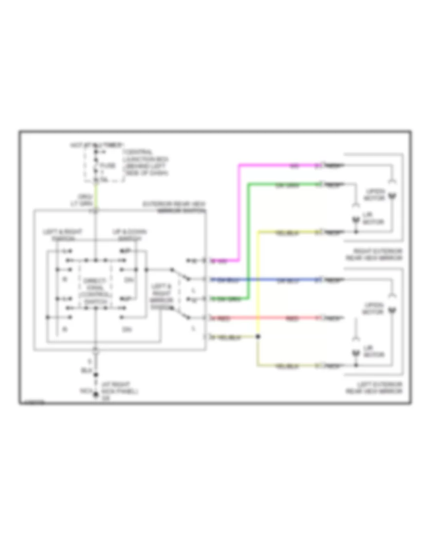
POWER MIRRORS
Power Mirrors Wiring Diagram for Mazda BSE 2003 4000
 https://portal-diagnostov.com/license.html
Automotive Electricians Portal FZCO
Automotive Electricians Portal FZCO
https://portal-diagnostov.com/license.html
https://portal-diagnostov.com/license.html
Automotive Electricians Portal FZCO
Automotive Electricians Portal FZCOList of elements for Power Mirrors Wiring Diagram for Mazda BSE 2003 4000:
- (at right kick panel) g9
- Central junction box (behind left side of dash)
- Direct- ional control switch
- Exterior rear view mirror switch
- Fuse 5a
- Hot at all times
- L/r motor
- Left & right mirror switch
- Left & right switch
- Left exterior rear view mirror
- Nca
- Red
- Right exterior rear view mirror
- Up & down switch
- Up/dn motor
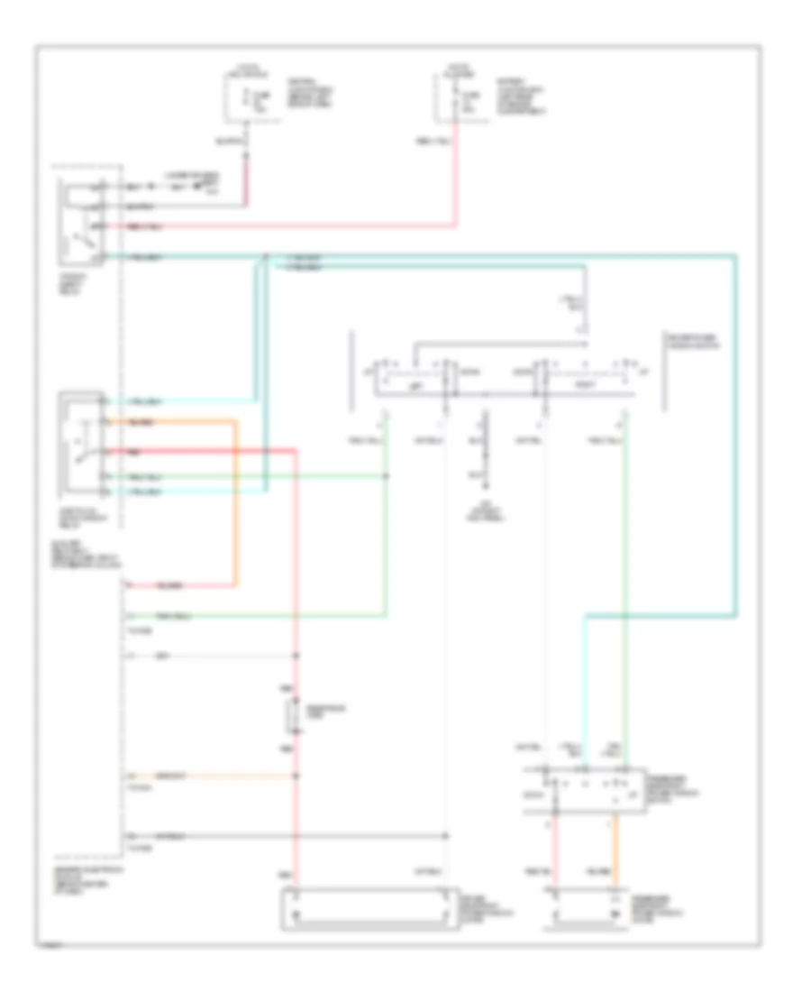
POWER WINDOWS
Power Windows Wiring Diagram for Mazda BSE 2003 4000
 https://portal-diagnostov.com/license.html
Automotive Electricians Portal FZCO
Automotive Electricians Portal FZCO
https://portal-diagnostov.com/license.html
https://portal-diagnostov.com/license.html
Automotive Electricians Portal FZCO
Automotive Electricians Portal FZCOList of elements for Power Windows Wiring Diagram for Mazda BSE 2003 4000:
- (under driver's seat)
- Auxiliary relay box 1 (behind dash, right of steering column)
- Battery junction box (left rear of engine compartment)
- Central junction box (behind left side of dash)
- Down
- Driver power window switch
- Driver side front power window motor
- Fuse 20a
- Fuse 7.5a
- G10
- G9 (at right kick panel)
- Generic electronic module (behind center of dash)
- Hot at all times
- Hot in acc or run
- Left
- One touch down window relay
- Passenger side front power window motor
- Passenger side front power window switch
- Red
- Resistance wire
- Right
- T-2100a
- T-2100b
- Window safety relay
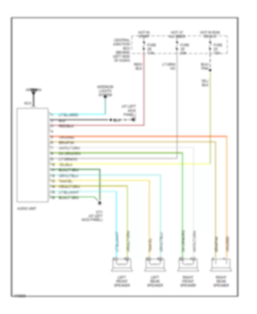
RADIO
Radio Wiring Diagram for Mazda BSE 2003 4000
 https://portal-diagnostov.com/license.html
Automotive Electricians Portal FZCO
Automotive Electricians Portal FZCO
https://portal-diagnostov.com/license.html
https://portal-diagnostov.com/license.html
Automotive Electricians Portal FZCO
Automotive Electricians Portal FZCOList of elements for Radio Wiring Diagram for Mazda BSE 2003 4000:
- (at left kick panel) g7
- Antenna
- Audio unit
- Central junction box (behind left side of dash)
- Fuse 20a
- Fuse 7.5a
- G11 (at left kick panel)
- Hot at all times
- Hot in run or acc
- Hot in start
- Interior lights system
- Left front speaker
- Left rear speaker
- Nca
- Right front speaker
- Right rear speaker
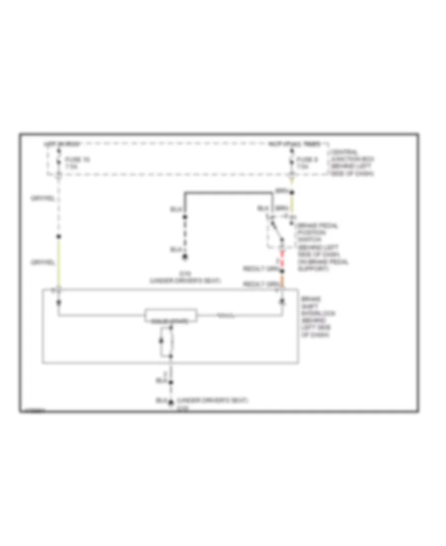
SHIFT INTERLOCK
Shift Interlock Wiring Diagram for Mazda BSE 2003 4000
 https://portal-diagnostov.com/license.html
Automotive Electricians Portal FZCO
Automotive Electricians Portal FZCO
https://portal-diagnostov.com/license.html
https://portal-diagnostov.com/license.html
Automotive Electricians Portal FZCO
Automotive Electricians Portal FZCOList of elements for Shift Interlock Wiring Diagram for Mazda BSE 2003 4000:
- (behind left side of dash, on brake pedal support)
- (under driver's seat)
- Brake pedal position switch
- Brake shift interlock (behind left side of dash)
- Central junction box (behind left side of dash)
- Fuse 10 7.5a
- Fuse 9 7.5a
- G10
- G10 (under driver's seat)
- Hot at all times
- Hot in run
- Solid state
STARTING/CHARGING
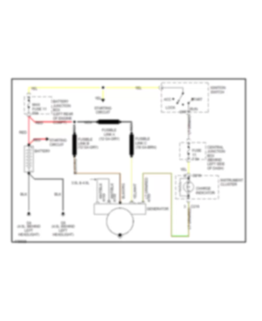
Charging Wiring Diagram for Mazda BSE 2003 4000
 https://portal-diagnostov.com/license.html
Automotive Electricians Portal FZCO
Automotive Electricians Portal FZCO
https://portal-diagnostov.com/license.html
https://portal-diagnostov.com/license.html
Automotive Electricians Portal FZCO
Automotive Electricians Portal FZCOList of elements for Charging Wiring Diagram for Mazda BSE 2003 4000:
- 3.0l & 4.0l
- A168
- A169
- Acc
- Battery
- Battery junction box (left rear of engine compt)
- C216
- Central junction box (behind left side of dash)
- Charge indicator
- Fuse 7.5a
- Fusible link a
- G4 (4.0l: behind left headlight)
- G6 (4.0l: behind left headlight)
- Generator
- Ignition switch
- Instrument cluster
- Lock
- Maxi fuse 11 50a
- Nca
- Off
- Red
- Run
- Start
- Starting circuit
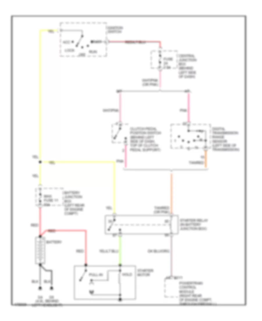
Starting Wiring Diagram for Mazda BSE 2003 4000
 https://portal-diagnostov.com/license.html
Automotive Electricians Portal FZCO
Automotive Electricians Portal FZCO
https://portal-diagnostov.com/license.html
https://portal-diagnostov.com/license.html
Automotive Electricians Portal FZCO
Automotive Electricians Portal FZCOList of elements for Starting Wiring Diagram for Mazda BSE 2003 4000:
- (4.0l: behind left headlight)
- A/t
- Acc
- B111
- Battery
- Battery junction box (left rear of engine compt)
- Central junction box (behind left side of dash)
- Clutch pedal position switch (behind left side of dash, top of clutch pedal support)
- Digital transmission range sensor (left side of transmission)
- Fuse 7.5a
- Hold
- Ignition switch
- Lock
- M/t
- Maxi fuse 11 50a
- Off
- Pnk
- Powertrain control module (right rear of engine compt, through firewall)
- Pull-in
- Red
- Run
- Start
- Starter motor
- Starter relay (in battery junction box)
- Tan/red
- Tan/red (or pnk)
SUPPLEMENTAL RESTRAINTS
Supplemental Restraints Wiring Diagram for Mazda BSE 2003 4000
 https://portal-diagnostov.com/license.html
Automotive Electricians Portal FZCO
Automotive Electricians Portal FZCO
https://portal-diagnostov.com/license.html
https://portal-diagnostov.com/license.html
Automotive Electricians Portal FZCO
Automotive Electricians Portal FZCOList of elements for Supplemental Restraints Wiring Diagram for Mazda BSE 2003 4000:
- (under center of dash) g8
- 1 ohm
- Air bag indicator
- Air bag sliding contact
- C-216
- Central junction box (behind left side of dash)
- Data link connector (dlc) (partial) (fastened to bottom of dash, near steering column)
- Driver air bag module
- Driver safety belt retractor pretensioner
- Fuse 11 7.5a
- Fuse 2 20a
- Fuse 26 10a
- Generic electronic module (gem) (behind center of dash)
- Hot at all times
- Hot in run
- Hot in run or start
- Instrument cluster
- Nca
- Note: shorting bar connectors are used on restraint control module harness connector when module is disconnected between pins 3 & 4, 6 & 7, 20 & 21
- Off
- Ohm
- Ohms
- Passenger air bag deactivation (pad) switch
- Passenger air bag module
- Passenger safety belt retractor pretensioner
- Restraint control module (behind center of dash)
- Shorting bar
- T-2100b
TRANSMISSION
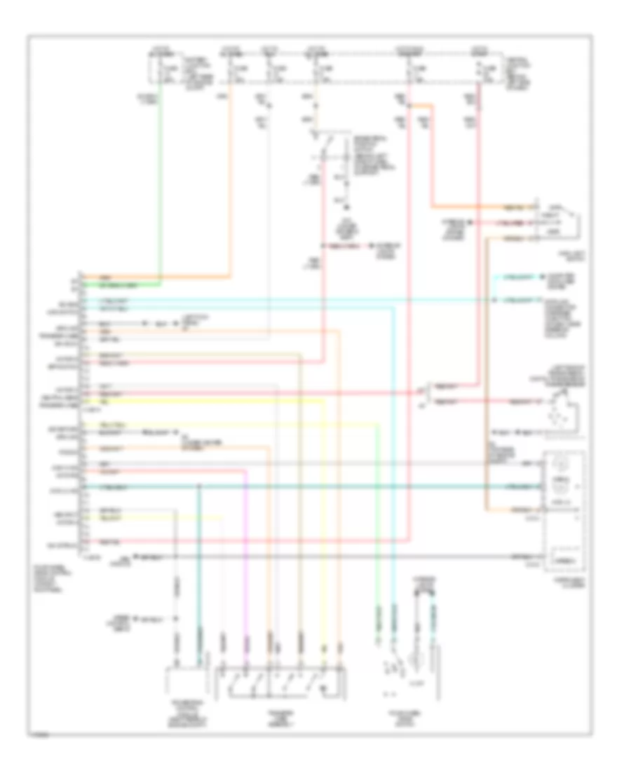
4WD Wiring Diagram for Mazda BSE 2003 4000
 https://portal-diagnostov.com/license.html
Automotive Electricians Portal FZCO
Automotive Electricians Portal FZCO
https://portal-diagnostov.com/license.html
https://portal-diagnostov.com/license.html
Automotive Electricians Portal FZCO
Automotive Electricians Portal FZCOList of elements for 4WD Wiring Diagram for Mazda BSE 2003 4000:
- (left kick panel) g7
- (left side of transmission) digital transmission range sensor
- 4wd hi
- 4wd hi ind
- 4wd lo
- 4wd lo ind
- 4wd switch
- A/t
- B-111
- Battery junction box (left rear of engine compt)
- Bpp switch
- Brake pedal position switch (behind left side of dash, on brake pedal support)
- C-214
- C-215
- Central junction box (behind left side of dash)
- Computer data lines system
- Data link connector (fastened to bottom of dash, near steering column)
- Exterior lights system
- Four-wheel drive control module (in right kick panel)
- Four-wheel drive switch
- Fuse 15a
- Fuse 20a
- Fuse 7.5a
- G10 (under driver's seat)
- G2 (top rear of engine compt)
- G8 (under center of dash)
- Gem module
- Ground
- H-281a
- H-281b
- Head
- Hot at all times
- Hot in run
- Hot in run or start
- Hot in start
- Ign (run)
- Ign (st/run)
- Illum
- Instrument cluster
- Interior lights system
- Interior lights system (dimmer)
- Iso bus
- M/t
- Main light switch
- Motor a
- Motor b
- Motor c
- Motor d
- Neutral sens
- Off
- Park
- Pos sw
- Powertrain control module (right rear of engine compt)
- Sig return
- Speed control servo
- Speedo
- Transfer case
- Transfer case assembly
- Vss input
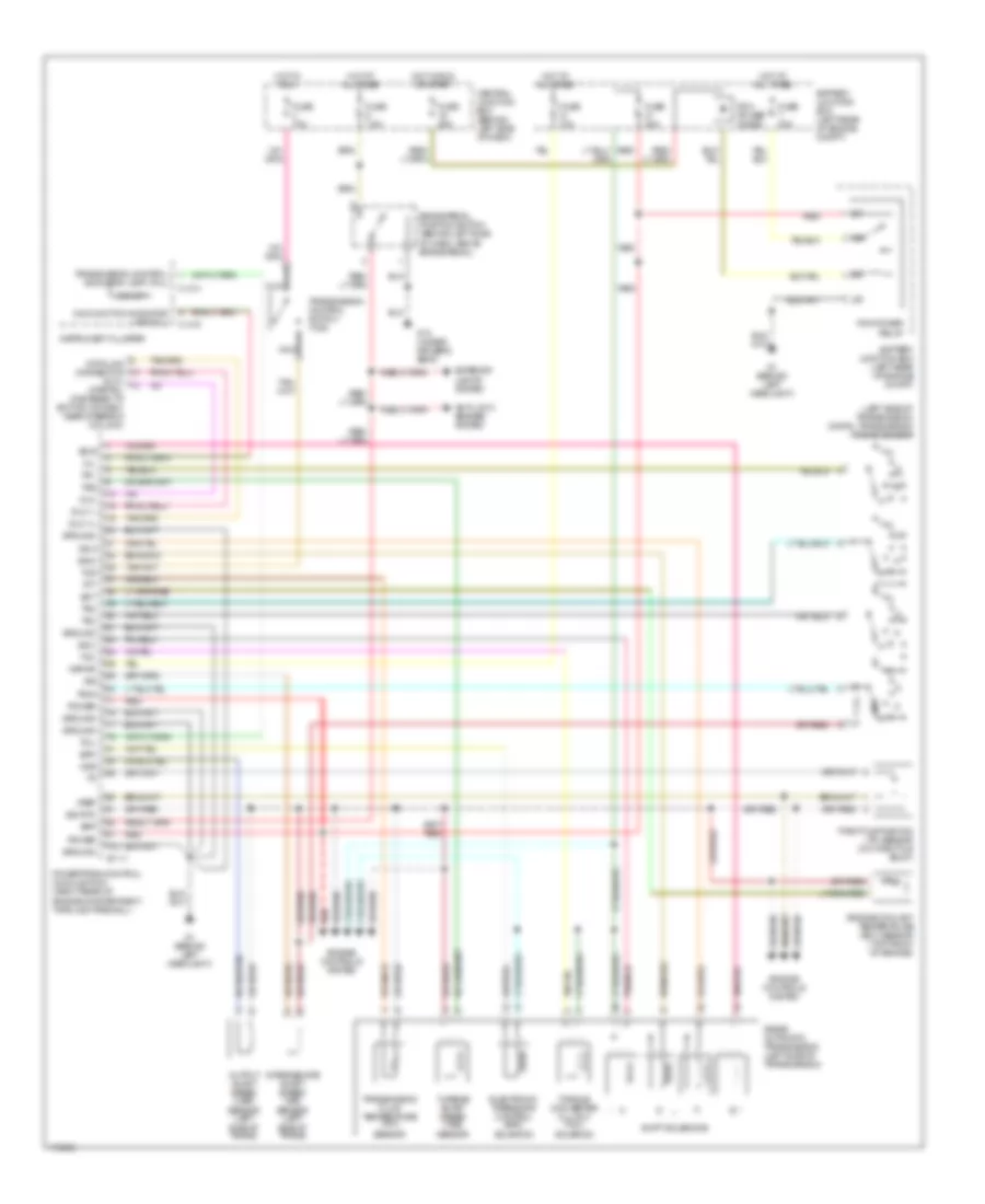
A/T Wiring Diagram for Mazda BSE 2003 4000
 https://portal-diagnostov.com/license.html
Automotive Electricians Portal FZCO
Automotive Electricians Portal FZCO
https://portal-diagnostov.com/license.html
https://portal-diagnostov.com/license.html
Automotive Electricians Portal FZCO
Automotive Electricians Portal FZCOList of elements for A/T Wiring Diagram for Mazda BSE 2003 4000:
- (dlc) (partial) (fastened to bottom of dash, near steering column)
- (left side of transmission) digital transmission range sensor
- 5r55e automatic transmission (left side of transmission)
- Anti-lock brakes system
- B-111
- Battery junction box (left rear of engine compt)
- Bpp
- Brake pedal position switch (behind left side of dash, above brake pedal)
- C-214
- C-215
- Central junction box (behind left side of dash)
- Data link connector
- Dlc
- Dlc (+)
- Dlc (-)
- Ect
- Electronic pressure control (epc) solenoid
- Engine controls system
- Engine coolant temperature (ect) sensor (top front of engine)
- Epc
- Exterior lights system
- Fuse 10a
- Fuse 20a
- Fuse 25a
- Fuse 30a
- Fuse 7.5a
- G1 (behind left headlight)
- G10 (under driver's seat)
- Ground
- Hot at all times
- Hot in run
- Hot in run or start
- Instrument cluster
- Intermediate shaft speed (iss) sensor (left side of trans)
- Iss
- Kapwr
- Malfunction indicator lamp (mil)
- Mil
- Nca
- O/d off
- Oss
- Output shaft speed (oss) sensor (left side of trans)
- Pcm power diode
- Pcm power relay
- Power
- Powertrain control module (pcm) (right rear of engine compartment, through firewall)
- R p
- Red
- Shift solenoids
- Sig rtn
- Ss a
- Ss b
- Ss c
- Ss d
- Tcc
- Tcil
- Tcs
- Tft
- Throttle position (tp) sensor (on throttle body)
- Torque converter clutch (tcc) solenoid
- Tr1
- Tr2
- Tr3a
- Tr4
- Transmission control indicator lamp (tcil)
- Transmission control switch (tcs)
- Transmission fluid temperature (tft) sensor
- Tss
- Turbine shaft speed (tss) sensor
- Vref
WARNING SYSTEMS
Warning Systems Wiring Diagram for Mazda BSE 2003 4000
 https://portal-diagnostov.com/license.html
Automotive Electricians Portal FZCO
Automotive Electricians Portal FZCO
https://portal-diagnostov.com/license.html
https://portal-diagnostov.com/license.html
Automotive Electricians Portal FZCO
Automotive Electricians Portal FZCOList of elements for Warning Systems Wiring Diagram for Mazda BSE 2003 4000:
- Battery junction box (left rear of engine compt)
- C214
- C215
- C216
- Central junction box (behind left side of dash)
- Door ajar indi- cator
- Driver safety belt retractor pretensioner
- Driver side rear door ajar switch
- Exterior lights system
- Fuse 10a
- Fuse 15a
- Fuse 7.5a
- G10 (left kick panel)
- G10 (under driver's seat)
- G8 (under center of dash)
- G9 (at right kick panel)
- Generic electronic module (behind center of dash)
- Head
- Hot at all times
- Hot in run
- Hot in run or start
- Ignition key switch
- Instrument cluster
- Left front door ajar switch
- Main light switch
- Nca
- Off
- Park
- Passenger side rear door ajar switch
- Right front door ajar switch
- Safety belt buckle switch (in left front safety belt buckle assembly)
- Safety belt indi- cator
- T-2100a
- T-2100b
- W/ 4 door
- W/ air bag
- W/o air bag
WIPER/WASHER
Wiper/Washer Wiring Diagram for Mazda BSE 2003 4000
 https://portal-diagnostov.com/license.html
Automotive Electricians Portal FZCO
Automotive Electricians Portal FZCO
https://portal-diagnostov.com/license.html
https://portal-diagnostov.com/license.html
Automotive Electricians Portal FZCO
Automotive Electricians Portal FZCOList of elements for Wiper/Washer Wiring Diagram for Mazda BSE 2003 4000:
- (4.0l: at left front corner of engine compt) g3
- (4.0l: at right rear corner of engine compt) g5
- Battery junction box (left rear of engine compartment)
- Central junction box (behind left side of dash)
- Fuse 16 30a
- Generic electronic module (behind center of dash)
- Hot in acc or run
- Int max
- Int min
- Multifunction switch
- Nca
- Off
- Red
- T-2100a
- T-2100b
- Tan/ red
- Tan/red
- Washer switch
- Windshield washer pump motor (on right front inner fender panel)
- Windshield washer relay
- Windshield wiper motor (top left center of firewall)
- Wiper high/low relay
- Wiper run/ park relay
- Wiper switch

 Čeština
 Dansk
Dansk Deutsch
 Ελληνικά
 English
 English
 Español
 Suomi
Suomi Français
 Français
 עברית
עברית Hrvatski
 Magyar
 Italiano
 日本語
日本語 한국어
한국어 Nederlands
 Polski
 Português
 Português
 Română
 Русский
 Slovenčina
 Slovenščina
 Svenska
 中文 (中国)
