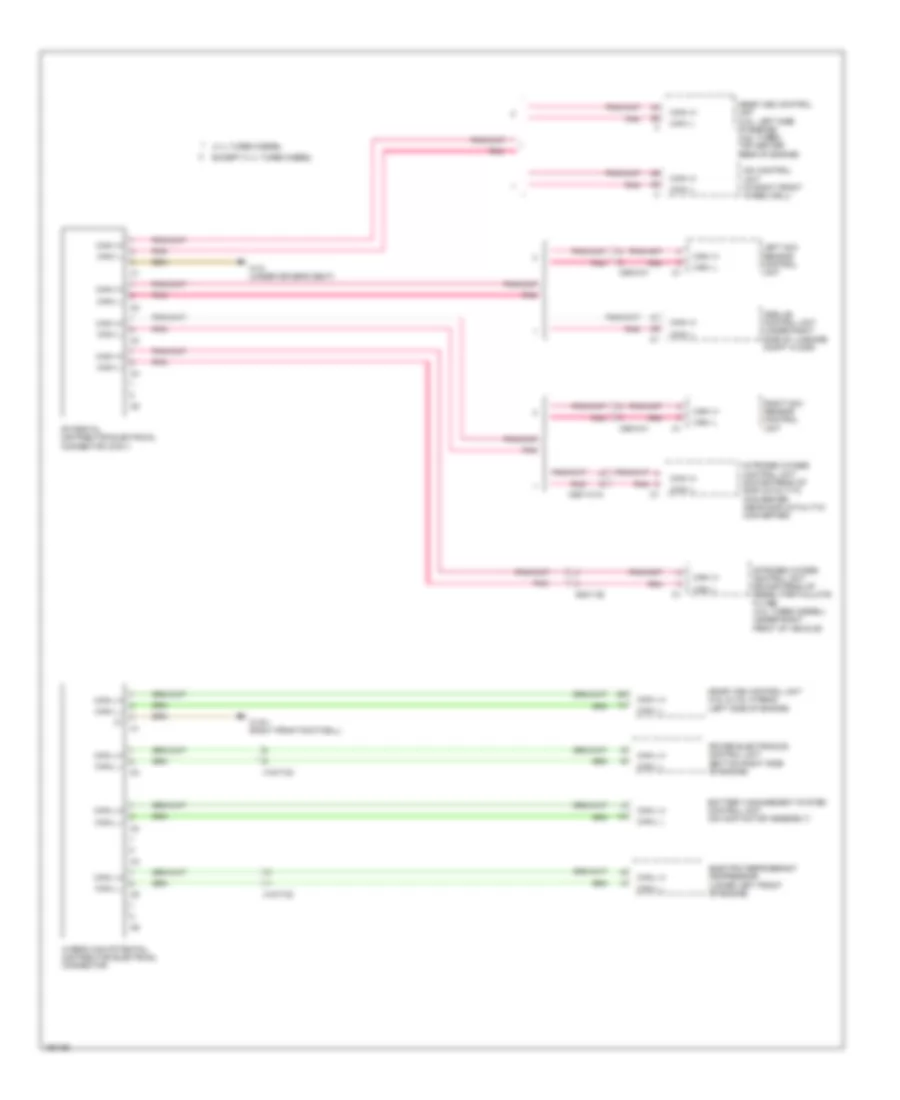
AIR CONDITIONING
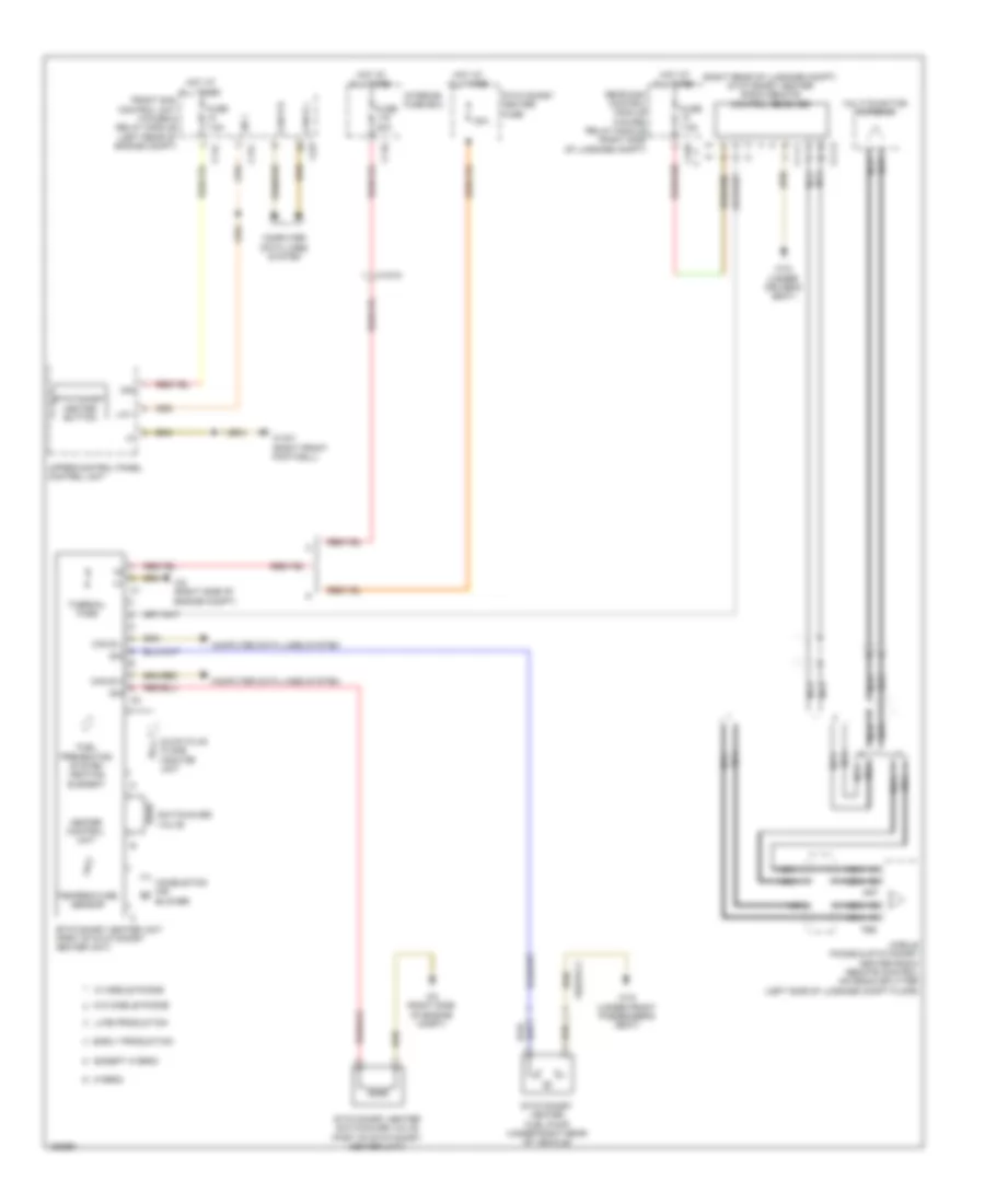
Automatic A/C Wiring Diagram, with Thermotronic (1 of 3) for Mercedes-Benz E250 Bluetec 4Matic 2014
 https://portal-diagnostov.com/license.html
Automotive Electricians Portal FZCO
Automotive Electricians Portal FZCO
https://portal-diagnostov.com/license.html
https://portal-diagnostov.com/license.html
Automotive Electricians Portal FZCO
Automotive Electricians Portal FZCO
List of elements for Automatic A/C Wiring Diagram, with Thermotronic (1 of 3) for Mercedes-Benz E250 Bluetec 4Matic 2014:
- (if equipped) refrigerant compressor magnetic clutch
- (left front footwell) w15/5
- (lower left side of radiator on refrigerant line) refrigerant pressure sensor
- (not used)
- 12v
- Automatic air conditioning control & operating unit
- C13d
- C14m
- C17c
- C18m
- C20m
- C21m
- C5c
- Can b h
- Can b l
- Computer data lines system
- Diesel
- Emissions sensor (right rear of engine compt)
- Evaporator temperature sensor (lower right side of hvac evaporator assembly)
- Front sam control module w/ fuse/ relay module (left rear of engine compt)
- Fuse 7.5a
- Gas
- Gnd
- Hot at all times
- Interior temperature sensor (left center of dash)
- Interior temperature sensor w/ integrated fan
- Left front footwell air outlet temperature sensor (left front footwell area)
- Left side air outlet temperature sensor (left side of dash)
- Lin
- Lin data
- Nca
- Overhead control panel control module (w/ tilting/sliding roof)
- Overhead control panel electronics (w/o tilting/sliding roof)
- Rear window heater button
- Refrigerant compressor regulation valve
- Right front footwell air outlet temperature sensor (right front footwell area)
- Right side air outlet temperature sensor (right side of dash)
- Sig
- Sig li
- Sig re
- Solid state
- Sun sensor (top center of dash)
- W15/5 (left front footwell)
- W15/7 (right front footwell)
- X25/2-c1
- X26-c1
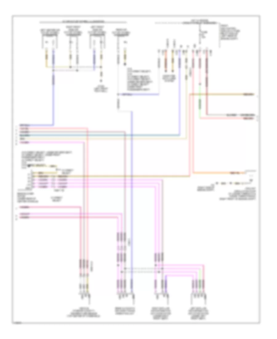
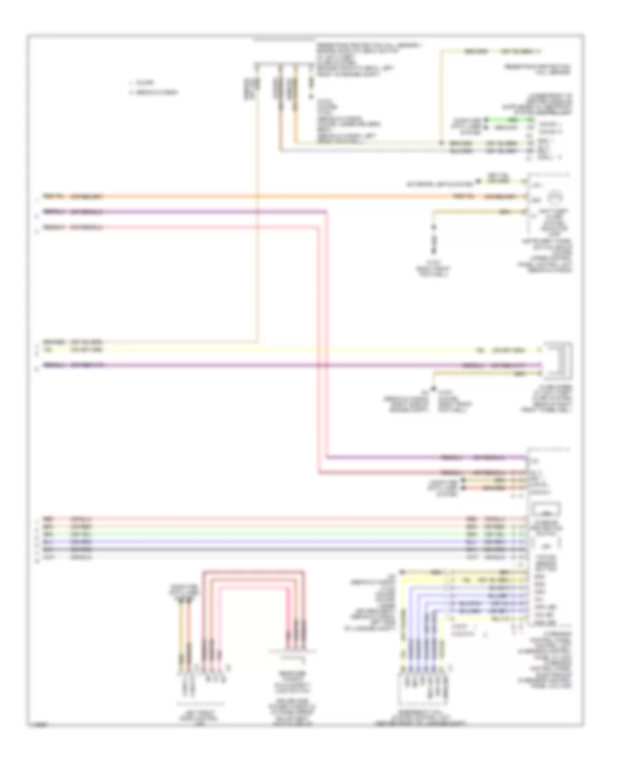
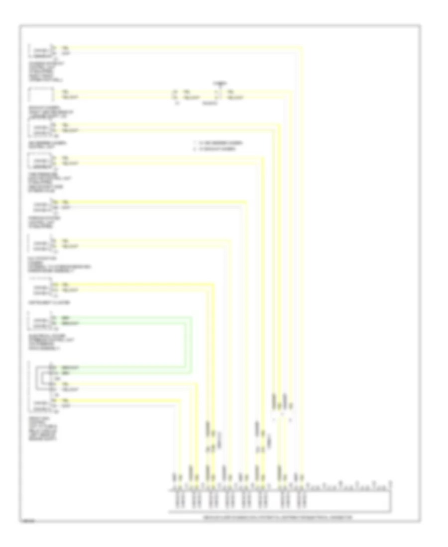
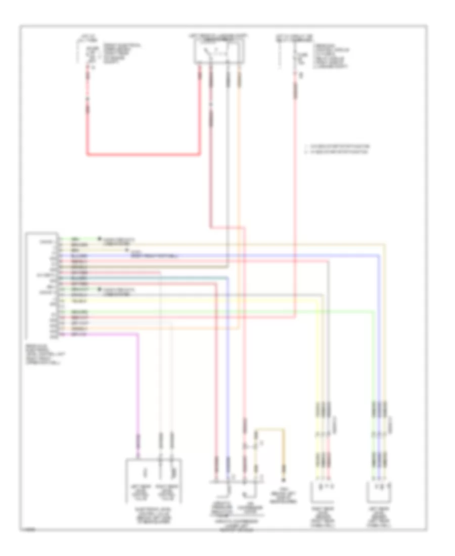
Automatic A/C Wiring Diagram, with Thermotronic (2 of 3) for Mercedes-Benz E250 Bluetec 4Matic 2014
 https://portal-diagnostov.com/license.html
Automotive Electricians Portal FZCO
Automotive Electricians Portal FZCO
https://portal-diagnostov.com/license.html
https://portal-diagnostov.com/license.html
Automotive Electricians Portal FZCO
Automotive Electricians Portal FZCOList of elements for Automatic A/C Wiring Diagram, with Thermotronic (2 of 3) for Mercedes-Benz E250 Bluetec 4Matic 2014:
- (w/o direct select: under driver's seat) (w/ direct select: under front passenger's seat) (w/ direct select) w19 (w/o direct select) w18
- 58d
- C14m
- C18m
- C19i
- C22i
- C3m
- C4i
- Can-b h
- Can-b l
- Computer data lines system
- Coolant circulation pump (w/ 2-zone thermatic & 3-zone thermotronic) (right front of engine compt)
- Front sam control module w/ fuse/ relay module (left rear of engine compt)
- Fuse 15a
- Gnd
- Hot w/ engine circuit 87 relay energized
- Left b-pillar air distribution actuator motor (under left front seat)
- Left center air outlet symbol illumination
- Left front side air outlet symbol illumination
- Lin
- Rear air outlet symbol illumination
- Rear automatic air conditioning operating unit
- Rear blower motor (under rear of center console)
- Right b-pillar air distribution actuator motor (under right front seat)
- Right front side air outlet symbol illumination
- Sig
- Vehicle interior humidity/ temperature sensor (top center of windshield)
- W/ air outlet symbol illumination
- W/ direct select
- W15/5 (left front footwell)
- W18 (w/o direct select) w19 (w/ direct select) (w/o direct select: under driver's seat) (w/ direct select: under front passenger's seat)
- W2 (right side of engine compt)
- X138/1-c2
- X18-c1
- X25/2-c1
- X83/11-c2
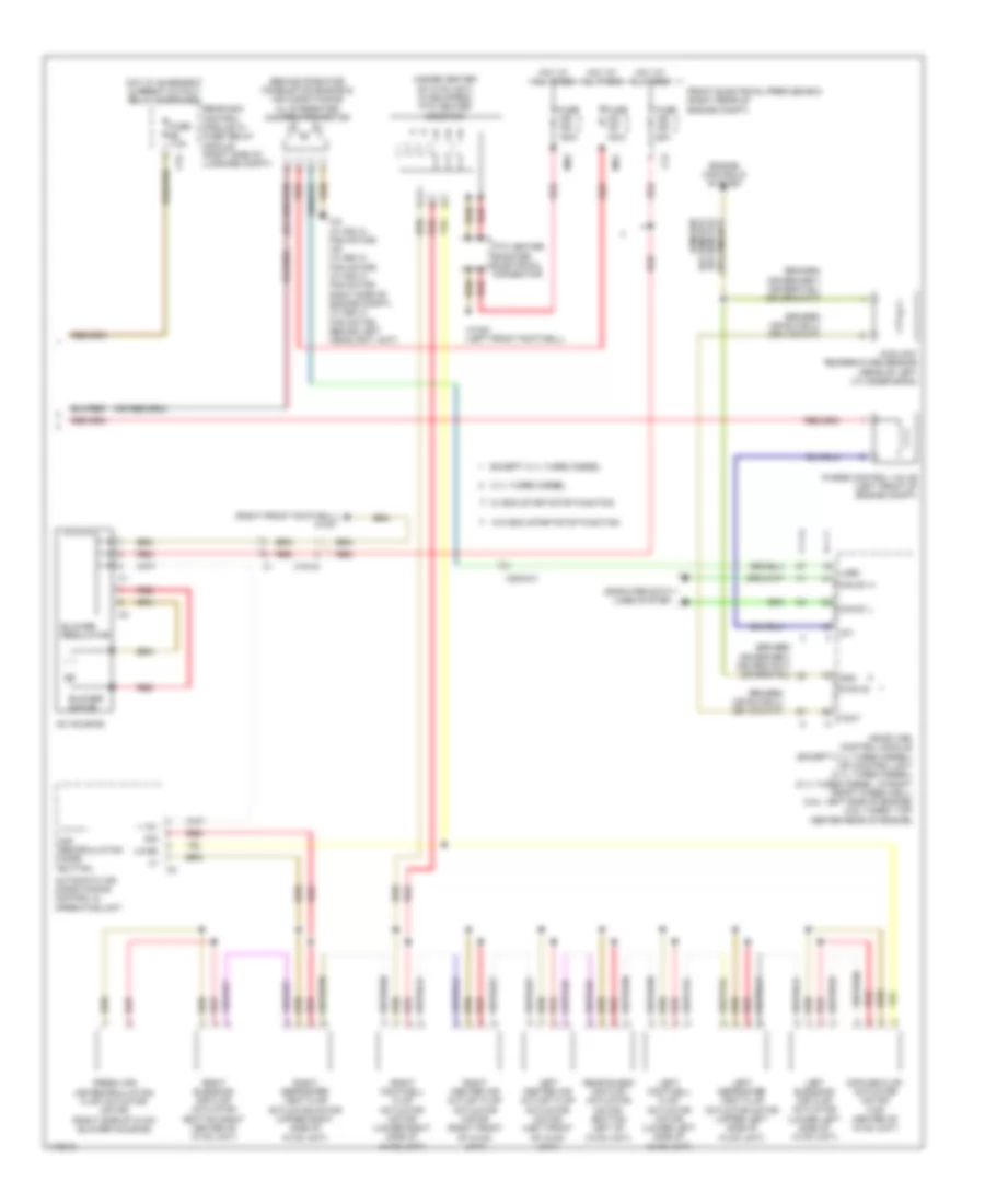
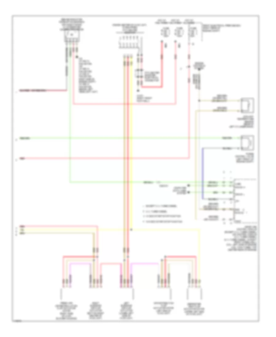
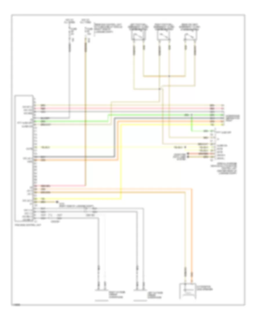
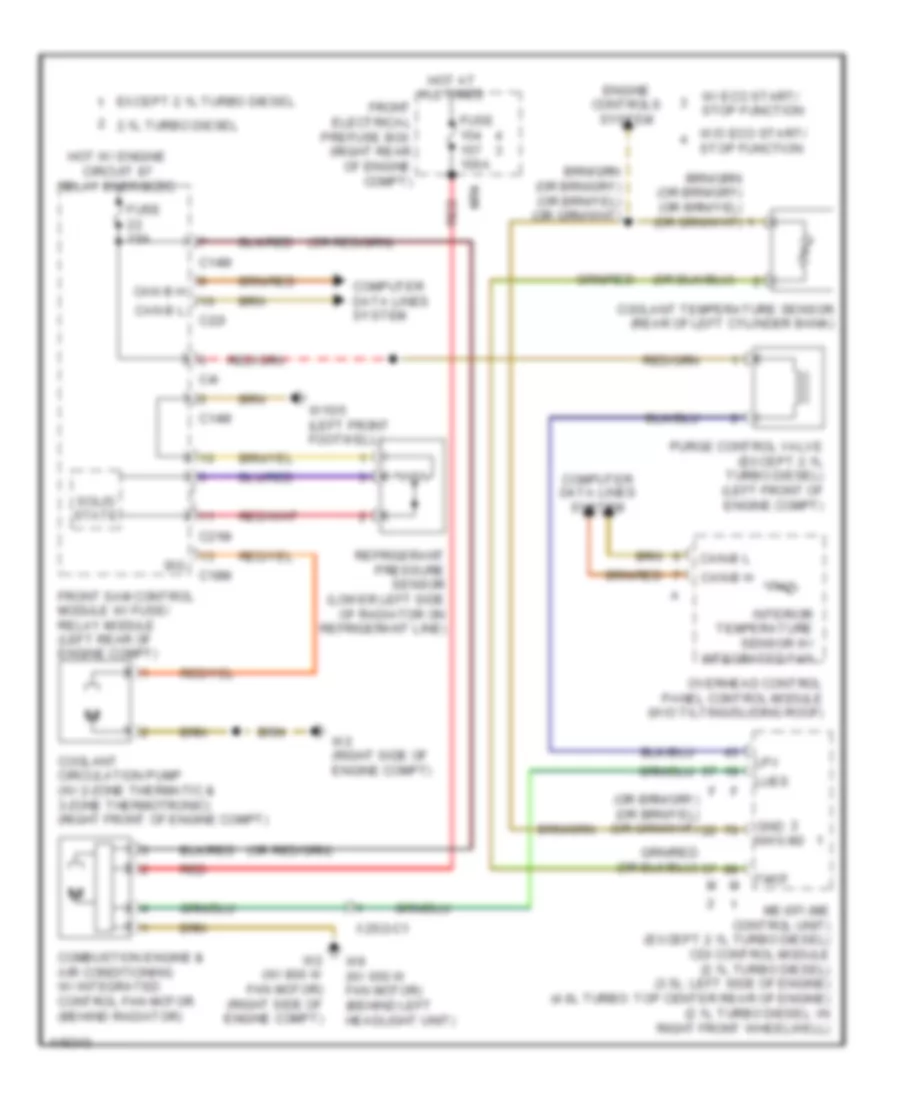
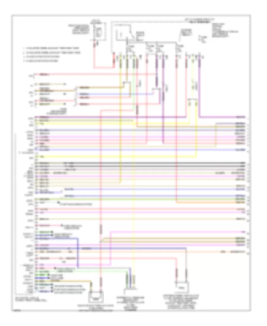
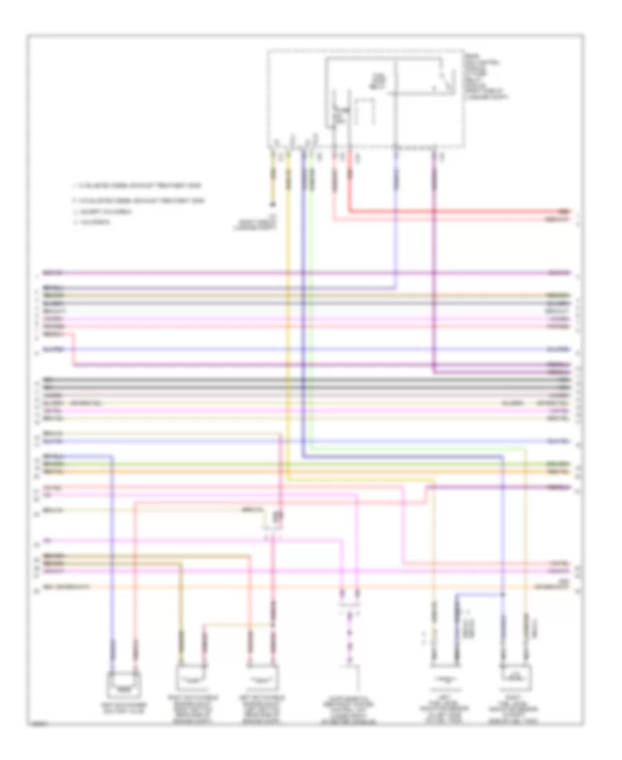
Automatic A/C Wiring Diagram, with Thermotronic (3 of 3) for Mercedes-Benz E250 Bluetec 4Matic 2014
 https://portal-diagnostov.com/license.html
Automotive Electricians Portal FZCO
Automotive Electricians Portal FZCO
https://portal-diagnostov.com/license.html
https://portal-diagnostov.com/license.html
Automotive Electricians Portal FZCO
Automotive Electricians Portal FZCOList of elements for Automatic A/C Wiring Diagram, with Thermotronic (3 of 3) for Mercedes-Benz E250 Bluetec 4Matic 2014:
- (behind radiator) combustion engine & air conditioning w/ integrated control fan motor
- (inside center of hvac unit) (if equipped) ptc heater booster
- (right front footwell) w15/7
- + 12v
- 2.1l turbo diesel
- Ac housing
- Air recirculation mode button
- Automatic air conditioning control & operating unit
- Blower motor
- Blower regulator
- C13
- Can e1 h
- Can e1 l
- Cfg
- Computer data lines system
- Coolant temperature sensor (rear of left cylinder bank)
- Diffuse flap actuator motor (top center of hvac unit)
- Engine controls system
- Except 2.1l turbo diesel
- Fresh air/ air recirculation flap actuator motor (right side of hvac blower housing)
- Front electrical prefuse box (right rear of engine compt)
- Fuse 100a
- Fuse 150a
- Fuse 50a
- Fuse 7.5a
- Gnd
- Hot at all times
- Hot w/ quiescent current cutout relay energized
- Left blending air flap actuator (lower left side of hvac unit)
- Left center air outlet flap actuator motor (left front of hvac unit)
- Left defroster vent flap actuator motor (upper left side of hvac unit)
- Left footwell flap actuator motor (lower left side of hvac unit)
- Lin b8
- Lpv f
- Lues
- Me-sfi (me) control module (except 2.1l turbo diesel) cdi control unit (2.1l turbo diesel) (2.1l turbo diesel: in right front wheelwell) (3.5l: left side of engine) (4.6l turbo: top center rear of engine)
- Mr4
- Mr5
- Nwg m2
- Ptc heater booster electrical connector
- Purge control valve (left front of engine compt)
- Rear blend air flap actuator motor (bottom left of hvac unit)
- Rear sam control module w/ fuse/ relay module (right side of luggage compt)
- Red
- Right blending air flap actuator (bottom right center of hvac unit)
- Right center air outlet flap actuator motor (right front of hvac unit)
- Right defroster vent flap actuator motor (upper right side of hvac unit)
- Right footwell flap actuator motor (lower right side of hvac unit)
- Sig
- Tmot m
- W/ eco start/stop function
- W/o eco start/stop function
- W15/5 (left front footwell)
- W2 (w/ 800 w fan motor) w9 (w/ 650 w fan motor) (w/ 800 w fan motor: right side of engine compt) (w/ 650 w fan motor: behind left headlight unit)
- X18-c4
- X25/2-c1
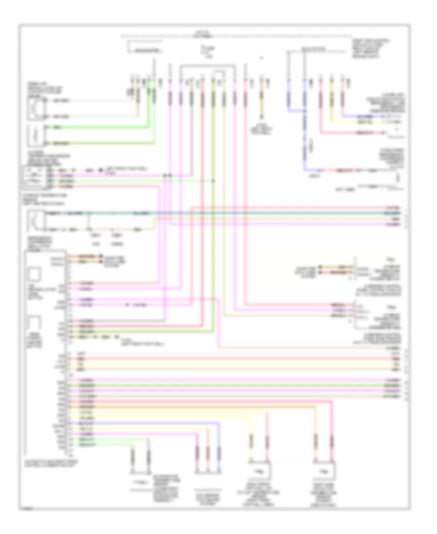
Automatic A/C Wiring Diagram, without Thermotronic (1 of 3) for Mercedes-Benz E250 Bluetec 4Matic 2014
 https://portal-diagnostov.com/license.html
Automotive Electricians Portal FZCO
Automotive Electricians Portal FZCO
https://portal-diagnostov.com/license.html
https://portal-diagnostov.com/license.html
Automotive Electricians Portal FZCO
Automotive Electricians Portal FZCOList of elements for Automatic A/C Wiring Diagram, without Thermotronic (1 of 3) for Mercedes-Benz E250 Bluetec 4Matic 2014:
- (if equipped) refrigerant compressor magnetic clutch
- (left front footwell) w15/5
- (lower left side of radiator on refrigerant line) refrigerant pressure sensor
- (not used)
- +12v
- 12v
- 30g
- Air recirculation mode button
- Automatic air conditioning control & operating unit
- C13d
- C14m
- C17c
- C20m
- C21m
- C5c
- Can b h
- Can b l
- Can-b h
- Can-b l
- Computer data lines system
- Diesel
- Evaporator temperature sensor (lower right side of hvac evaporator assembly)
- Fresh air/ recirculated air flap switchover valve
- Front sam control module w/ fuse/ relay module (left rear of engine compt)
- Fuse 7.5a
- Gas
- Gnd
- Hot at all times
- Interior temperature sensor (left center of dash)
- Interior temperature sensor w/ integrated fan
- Lin b8
- Nca
- Ntc (+)
- Ntc (-)
- Outside temperature sensor (behind center of front bumper)
- Overhead control panel control module (w/ tilting/sliding roof)
- Overhead control panel electronics (w/o tilting/sliding roof)
- Rear window heater button
- Red
- Refrigerant compressor regulation valve
- Right front footwell air outlet temperature sensor (right front footwell area)
- Right side air outlet temperature sensor (in right side of dash)
- Sig
- Sig li
- Sig re
- Solid state
- Sun sensor (top center of dash)
- W15/5 (left front footwell)
- X25/2-c1
- X26-c1
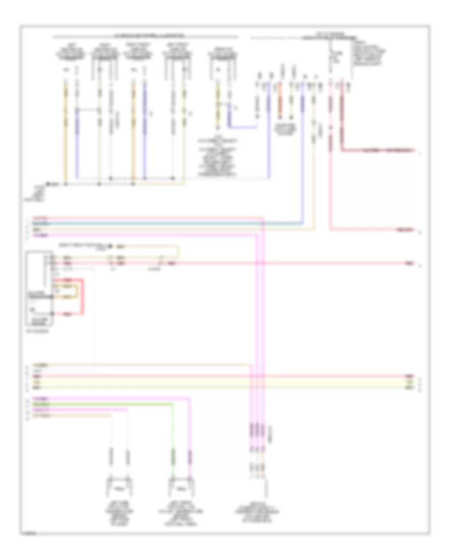
Automatic A/C Wiring Diagram, without Thermotronic (2 of 3) for Mercedes-Benz E250 Bluetec 4Matic 2014
 https://portal-diagnostov.com/license.html
Automotive Electricians Portal FZCO
Automotive Electricians Portal FZCO
https://portal-diagnostov.com/license.html
https://portal-diagnostov.com/license.html
Automotive Electricians Portal FZCO
Automotive Electricians Portal FZCOList of elements for Automatic A/C Wiring Diagram, without Thermotronic (2 of 3) for Mercedes-Benz E250 Bluetec 4Matic 2014:
- (right front footwell) w15/7
- 58d
- Ac housing
- Blower motor
- Blower regulator
- C14m
- C17c
- C18m
- C19i
- C22i
- C3m
- C4i
- Can-b h
- Can-b l
- Computer data lines system
- Front sam control module w/ fuse/ relay module (left rear of engine compt)
- Fuse 15a
- Hot w/ engine circuit 87 relay energized
- Left center air outlet symbol illumination
- Left front footwell air outlet temperature sensor (left front footwell area)
- Left front side air outlet symbol illumination
- Left side air outlet temperature sensor (left side of dash)
- Rear air outlet symbol illumination
- Red
- Right center air outlet symbol illumination
- Right front side air outlet symbol illumination
- Vehicle interior humidity/ temperature sensor (top center of windshield)
- W/ air outlet symbol illumination
- W15/5 (left front footwell)
- W18 (w/o direct select) w19 (w/ direct select) (w/o direct select: under driver's seat) (w/ direct select: (under front passenger's seat)
- X157/1-c2
- X18-c4
- X25/2-c1
- X83/11-c2
Automatic A/C Wiring Diagram, without Thermotronic (3 of 3) for Mercedes-Benz E250 Bluetec 4Matic 2014
 https://portal-diagnostov.com/license.html
Automotive Electricians Portal FZCO
Automotive Electricians Portal FZCO
https://portal-diagnostov.com/license.html
https://portal-diagnostov.com/license.html
Automotive Electricians Portal FZCO
Automotive Electricians Portal FZCOList of elements for Automatic A/C Wiring Diagram, without Thermotronic (3 of 3) for Mercedes-Benz E250 Bluetec 4Matic 2014:
- (behind radiator) combustion engine & air conditioning w/ integrated control fan motor
- (inside center of hvac unit) (if equipped) ptc heater booster
- 2.1l turbo diesel
- Air distribution flap actuator motor (left end of hvac unit)
- Can e1 h
- Can e1 l
- Computer data lines system
- Coolant temperature sensor (rear of left cylinder bank)
- Defroster vent flap actuator motor (upper left end of hvac unit)
- Engine controls system
- Except 2.1l turbo diesel
- Fresh air/ air recirculation flap actuator motor (right side of hvac blower housing)
- Front electrical prefuse box (right rear of engine compt)
- Fuse 100a
- Fuse 150a
- Fuse 50a
- Gnd
- Hot at all times
- Left blending air flap actuator (lower left side of hvac unit)
- Lpv
- Lues
- Me-sfi (me) control module (except 2.1l turbo diesel) cdi control module (2.1l turbo diesel) (2.1l turbo diesel: in right front wheelwell) (3.5l: left side of engine) (4.6l twin turbo: top center rear of engine)
- Mr4
- Mr5
- Nwg m2
- Ptc heater booster electrical connector
- Purge control valve (left front of engine compt)
- Red
- Right blending air flap actuator (bottom right center of hvac unit)
- Tmot
- W/ eco start/stop function
- W/o eco start/stop function
- W15/7 (right front footwell)
- W2 (w/ 800 w fan motor) w9 (w/ 650 w fan motor) (w/ 800 w fan motor: right side of engine compt) (w/ 650 w fan motor: behind left headlight unit)
- X25/2-c1
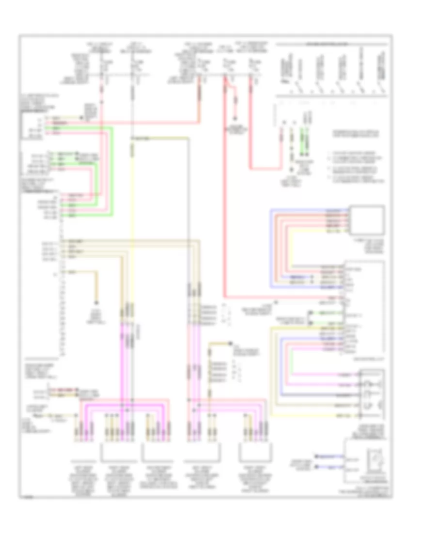
ANTI-LOCK BRAKES
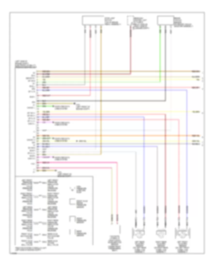
Anti-lock Brakes Wiring Diagram (1 of 2) for Mercedes-Benz E250 Bluetec 4Matic 2014
 https://portal-diagnostov.com/license.html
Automotive Electricians Portal FZCO
Automotive Electricians Portal FZCO
https://portal-diagnostov.com/license.html
https://portal-diagnostov.com/license.html
Automotive Electricians Portal FZCO
Automotive Electricians Portal FZCOList of elements for Anti-lock Brakes Wiring Diagram (1 of 2) for Mercedes-Benz E250 Bluetec 4Matic 2014:
- (-)
- (left side of engine compt) electronic stability program control unit
- +12v
- 30g
- Bla
- Bls-h
- Bls-m
- Bls-v
- Bls_l
- Brake vacuum sensor (on brake vacuum booster assembly)
- Can e1 h
- Can e1 l
- Can h h
- Can h l
- Computer data lines system
- Df hl (+)
- Df hl s
- Df hr (+)
- Df hr s
- Df vl (+)
- Df vl s
- Df vr (+)
- Df vr s
- Front axle brake pressure sensor
- Front axle intake ball valve
- Front axle switchover valve
- Front pressure sensor
- High pressure & return pump
- Left front axle rpm sensor (on left front wheel hub assembly)
- Left front pressure regulator valve (pressure hold)
- Left front pressure regulator valve (pressure release)
- Left rear axle rpm sensor (on left rear wheel hub assembly)
- Left rear pressure regulator valve (pressure hold)
- Left rear pressure regulator valve (pressure release)
- Nca
- Rear axle intake ball valve
- Rear axle switchover valve
- Rear pressure sensor
- Rear sam control unit w/ fuse & relay module (right side of c9i luggage compt)
- Right front pressure regulator valve (pressure hold)
- Right front pressure regulator valve (pressure release)
- Right rear axle rpm sensor (on right rear wheel hub assembly)
- Right rear pressure regulator valve (pressure hold)
- Right rear pressure regulator valve (pressure release)
- Sig
- Ssk-stat
- Stop lamp switch (top of brake pedal assembly)
- Traction system hydraulic unit (left side of engine compt)
- W70 (left front of engine compt)
- Yaw rate, lateral & longitudinal acceleration sensor (under front passenger's seat)
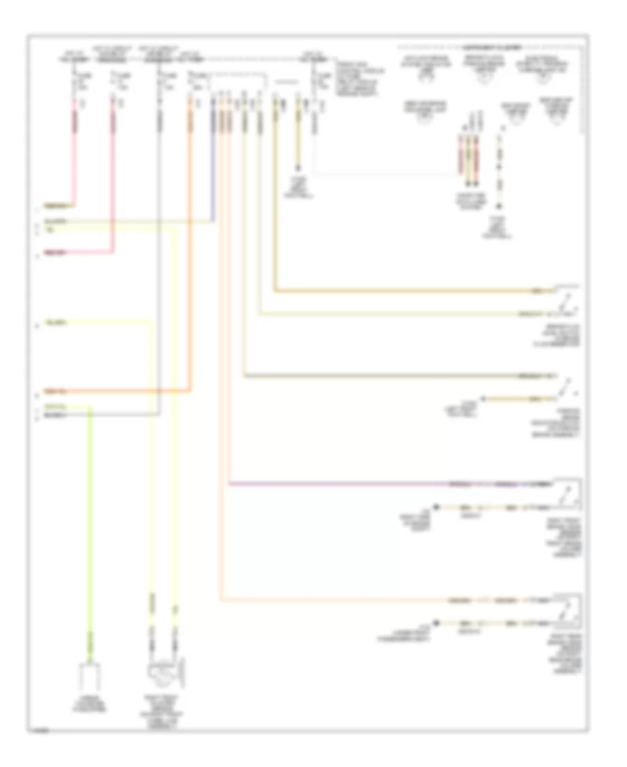
Anti-lock Brakes Wiring Diagram (2 of 2) for Mercedes-Benz E250 Bluetec 4Matic 2014
 https://portal-diagnostov.com/license.html
Automotive Electricians Portal FZCO
Automotive Electricians Portal FZCO
https://portal-diagnostov.com/license.html
https://portal-diagnostov.com/license.html
Automotive Electricians Portal FZCO
Automotive Electricians Portal FZCOList of elements for Anti-lock Brakes Wiring Diagram (2 of 2) for Mercedes-Benz E250 Bluetec 4Matic 2014:
- Antilock brake system indicator lamp
- Brake fluid & parking brake lamp ind
- Brake fluid level switch (in brake fluid reservoir)
- C11c
- C15m
- C19i
- C20m
- C22i
- C2i
- C7i
- Can b h
- Can b l
- Computer data lines system
- Electronic stability program warning lamp ind
- Esp sport lamp ind
- Esp/asr off warning lamp ind
- Front sam control module w/ fuse/ relay module (left rear of engine compt)
- Fuse 25a
- Fuse 40a
- Fuse 7.5a
- Hot at all times
- Hot w/ circuit 15r relay energized
- Hot w/ circuit 30g relay energized
- Instrument cluster
- Mirror taximeter (if equipped)
- Nca
- Parking brake indicator switch (on parking brake assembly)
- Right front axle rpm sensor (on right front wheel hub assembly)
- Right front brake wear sensor (on right front brake caliper assembly)
- Right rear brake wear sensor (on right rear brake caliper assembly)
- Service brake indicator lamp
- W15/2 (left front footwell)
- W15/5 (left front footwell)
- W19 (under front passenger's seat)
- W2 (right side of engine compt)
- X62/33-c1
- X62/6-c1
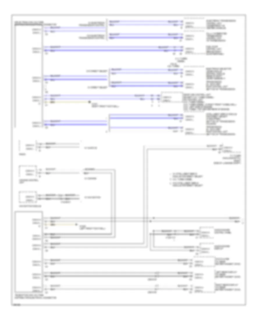
ANTI-THEFT
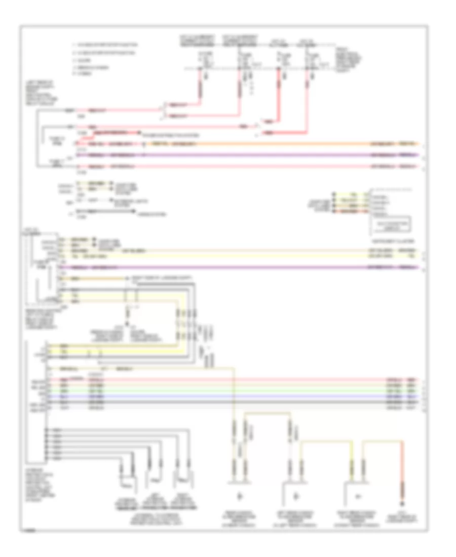
Anti-theft Alarm Wiring Diagram (1 of 2) for Mercedes-Benz E250 Bluetec 4Matic 2014
 https://portal-diagnostov.com/license.html
Automotive Electricians Portal FZCO
Automotive Electricians Portal FZCO
https://portal-diagnostov.com/license.html
https://portal-diagnostov.com/license.html
Automotive Electricians Portal FZCO
Automotive Electricians Portal FZCOList of elements for Anti-theft Alarm Wiring Diagram (1 of 2) for Mercedes-Benz E250 Bluetec 4Matic 2014:
- (+)
- (integral to interior protection & tow-away protection control unit)
- (left rear of engine compt) front sam control module w/ fuse/ relay module
- (or red)
- (right side of luggage compt) w7
- 12v
- 30g
- 56a
- 58d
- Ass led
- Ass off
- C11c
- C13d
- C15m
- C16s
- C22i
- C3i
- C7i
- C8d
- C8s
- C9i
- Can b h
- Can b l
- Can e2 h
- Can e2 l
- Computer data lines system
- Coupe
- Ewd
- Exterior lights system
- Front electrical prefuse box (right rear of engine compt)
- Fuse 100a
- Fuse 150a
- Fuse 17 30a
- Fuse 18 7.5a
- Fuse 46 7.5a
- Horns system
- Hot at all times
- Hot w/ quiescent current cutout relay energized
- Hybrid
- Instrument cluster
- Interior protection & tow-away protection control unit (if equipped) (front center of roof)
- Interior protection receiver
- Irs led
- Irs-off
- Left interior protection transmitter
- Left rear window glass breakage sensor (in left rear window)
- Lin b4
- Mg1
- Mr2
- Mr7
- Mrg2
- Multi-function display
- Nca
- Power distribution system
- Rear sam control unit w/ fuse & relay module (right side of luggage compt)
- Rear window glass breakage sensor (in rear window)
- Red
- Right interior protection transmitter
- Right rear window glass breakage sensor (in right rear window)
- Sedan
- Sedan & wagon
- W/ eco start/stop function
- W/o eco start/stop function
- W7 (coupe) (right side of luggage compt)
- W7/1 (right rear of luggage compt)
- W7/8 (sedan & wagon) (right side of luggage compt)
- Wagon
- X18/2
- X18/2-c1
- X42/28-c1
- X8/45-c4
- X8/46-c1
- X8/47-c2
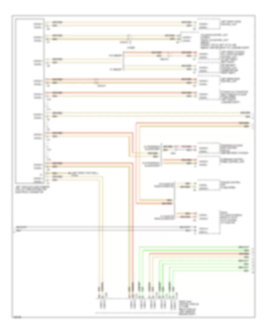
Anti-theft Alarm Wiring Diagram (2 of 2) for Mercedes-Benz E250 Bluetec 4Matic 2014
 https://portal-diagnostov.com/license.html
Automotive Electricians Portal FZCO
Automotive Electricians Portal FZCO
https://portal-diagnostov.com/license.html
https://portal-diagnostov.com/license.html
Automotive Electricians Portal FZCO
Automotive Electricians Portal FZCOList of elements for Anti-theft Alarm Wiring Diagram (2 of 2) for Mercedes-Benz E250 Bluetec 4Matic 2014:
- (or red)
- 12v
- 30g
- 30g can b l
- Alarm siren (w/ anti-theft alarm system) (rear of right front wheelwell)
- Anti-theft alarm system indicator lamp
- Can b h
- Can e1 h
- Can e1 l
- Can-b h
- Can-b l
- Computer data lines system
- Coupe
- Driver side power window & outside mirror adjustment switch group
- Emergency call system control unit (center front of luggage compt)
- Exterior lights system
- Gnd
- Info
- Info led
- Instrument panel switch group (coupe) upper control panel control unit (sedan & wagon)
- Interior protection switch
- Left front door control unit
- Lin 1
- Off
- Overhead control panel control unit (overhead control panel w/ can) overhead control panel electronics (overhead control panel w/o can)
- Pedestrian protection hall sensor
- Pedestrian protection hall sensor + engine hood ata (edw) switch (w/ anti-theft alarm system) (engine hood ata (edw): left front of engine compt)
- Pnk
- Rear side window child safety lock switch
- Red
- Sedan & wagon
- Sig mhs li c1
- Sos
- Sos led
- Towing sensor button
- W15/7 (coupe) (right front footwell)
- W15/7 (right front footwell)
- W18/3 (coupe) w15/2 (sedan & wagon) (coupe: under driver's seat) (sedan & wagon: left front footwell)
- W2 (sedan & wagon) (right side of engine compt)
- W6 (sedan & wagon) w18/3 (coupe) (coupe: under driver's seat) (sedan & wagon: left side of luggage compt)
- Ws led
- X18/37
- X18/37-c1
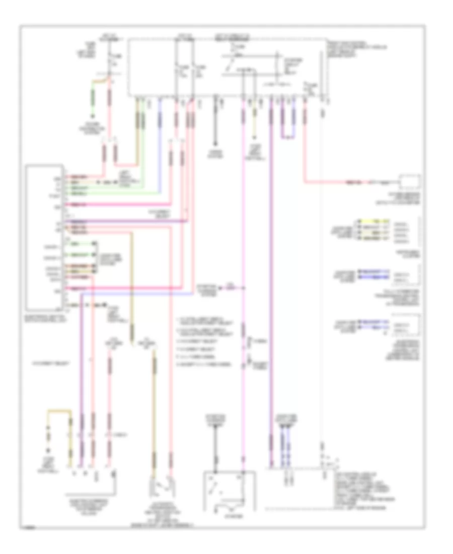
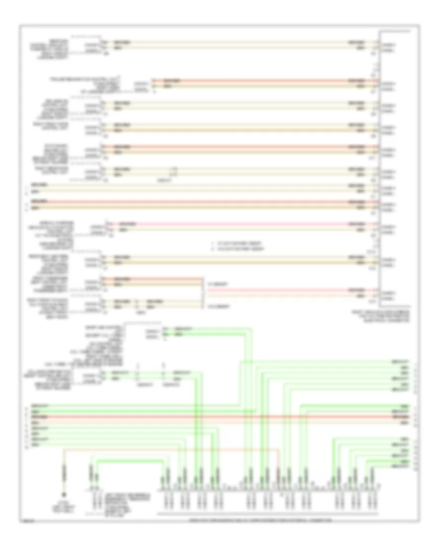
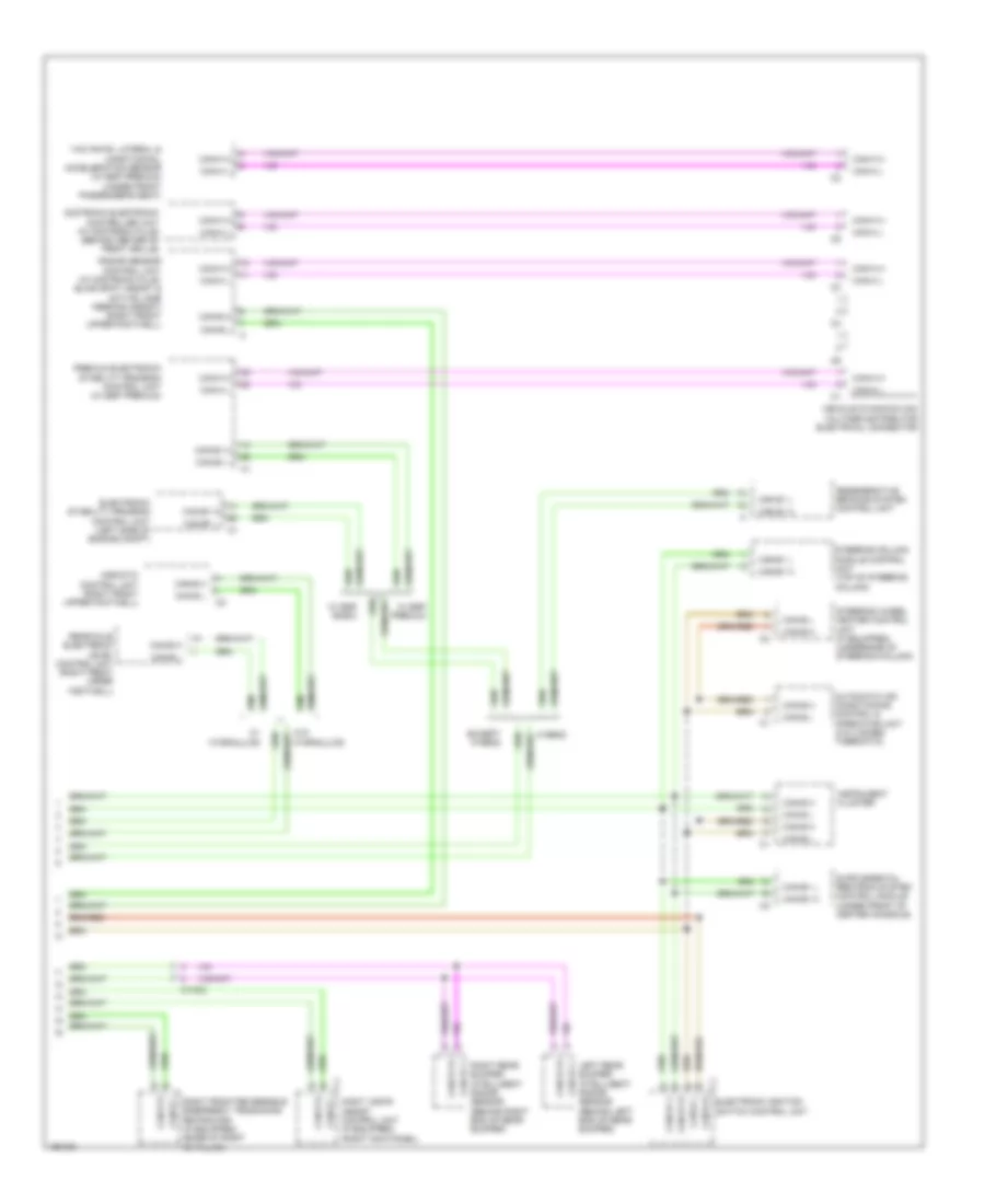
Drive Authorization System Wiring Diagram for Mercedes-Benz E250 Bluetec 4Matic 2014
 https://portal-diagnostov.com/license.html
Automotive Electricians Portal FZCO
Automotive Electricians Portal FZCO
https://portal-diagnostov.com/license.html
https://portal-diagnostov.com/license.html
Automotive Electricians Portal FZCO
Automotive Electricians Portal FZCOList of elements for Drive Authorization System Wiring Diagram for Mercedes-Benz E250 Bluetec 4Matic 2014:
- (+)
- (left front footwell) w15/5
- 2.1l turbo diesel
- 30b
- 30z
- Automatic transmission neutral position switch (w/ keyless go) (base of shift lever assembly)
- C11c
- C15m
- C17c
- C3m
- C4i
- C5c
- C6i
- Can b h
- Can b l
- Can c h
- Can c l
- Can e h
- Can e l
- Can e1 h
- Can e1 l
- Cdi control module (2.1l turbo diesel) me-sfi (me) control unit (except 2.1l turbo diesel) (2.1l turbo diesel: in right front wheelwell) (4.6l turbo: top center rear of engine) (3.5l: left side of engine)
- Computer data lines system
- Data
- Electric steering lock control unit (on steering column)
- Electronic ignition switch control unit
- Electronic transmission control unit (under front of center console)
- Except 2.1l turbo diesel
- Except hybrid
- Front sam control module w/fuse/relay module (left rear of engine compt)
- Fully integrated transmission control control unit (in transmission)
- Fuse 15a
- Fuse 20a
- Fuse 5a
- Fuse 7.5a
- Fuse box (left end of dash)
- Horns system
- Hot at all times
- Hot w/ circuit 15 relay energized
- Hybrid
- Instrument cluster
- Module for direct select
- Nca
- Oxygen sensor upstream of catalytic converter
- P not
- Power distribution system
- Starter
- Starter circuit relay
- Starting/ charging system
- Str
- W/ direct select
- W/ intelligent servo
- W/ keyless go
- W/o direct select
- W/o intelligent servo
- W/o keyless go
- W15/5 (left front footwell)
- X190-c1
- X26-c1
Panic Alarm Wiring Diagram for Mercedes-Benz E250 Bluetec 4Matic 2014
 https://portal-diagnostov.com/license.html
Automotive Electricians Portal FZCO
Automotive Electricians Portal FZCO
https://portal-diagnostov.com/license.html
https://portal-diagnostov.com/license.html
Automotive Electricians Portal FZCO
Automotive Electricians Portal FZCOList of elements for Panic Alarm Wiring Diagram for Mercedes-Benz E250 Bluetec 4Matic 2014:
- 13a
- Alarm on
- Can b h
- Can b l
- Computer data lines system
- Fuse 15a
- Fuse 5a
- Hot at all times
- Left footwell emergency alarm system button
- Left outside mirror microphone
- Ls (+)
- Ls (-)
- Mic gnd
- Mic ii (+)
- Mic ii (-)
- Mic ls (+)
- Mic ls (-)
- Mic nf (+)
- Mic re (+)
- Mic re (-)
- Mic vcc
- Microphone separation point
- Mute
- Nca
- Outside pas (gas) speaker
- Pas (gas) control unit
- Ptt alrm off
- Rear air vent emergency alarm system button
- Rear sam control unit w/ fuse & relay module (right side of luggage compt)
- Red
- Right footwell emergency alarm system button
- Right outside mirror microphone
- Scr
- Special-purpose vehicle multi-function control unit (center front of luggage compt)
- W7/8 (right side of luggage compt)
- Wsa
- X35/1-ev
- X35/2-ev
BODY CONTROL MODULES
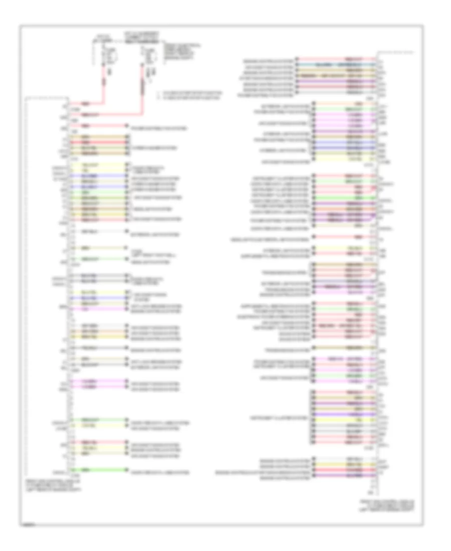
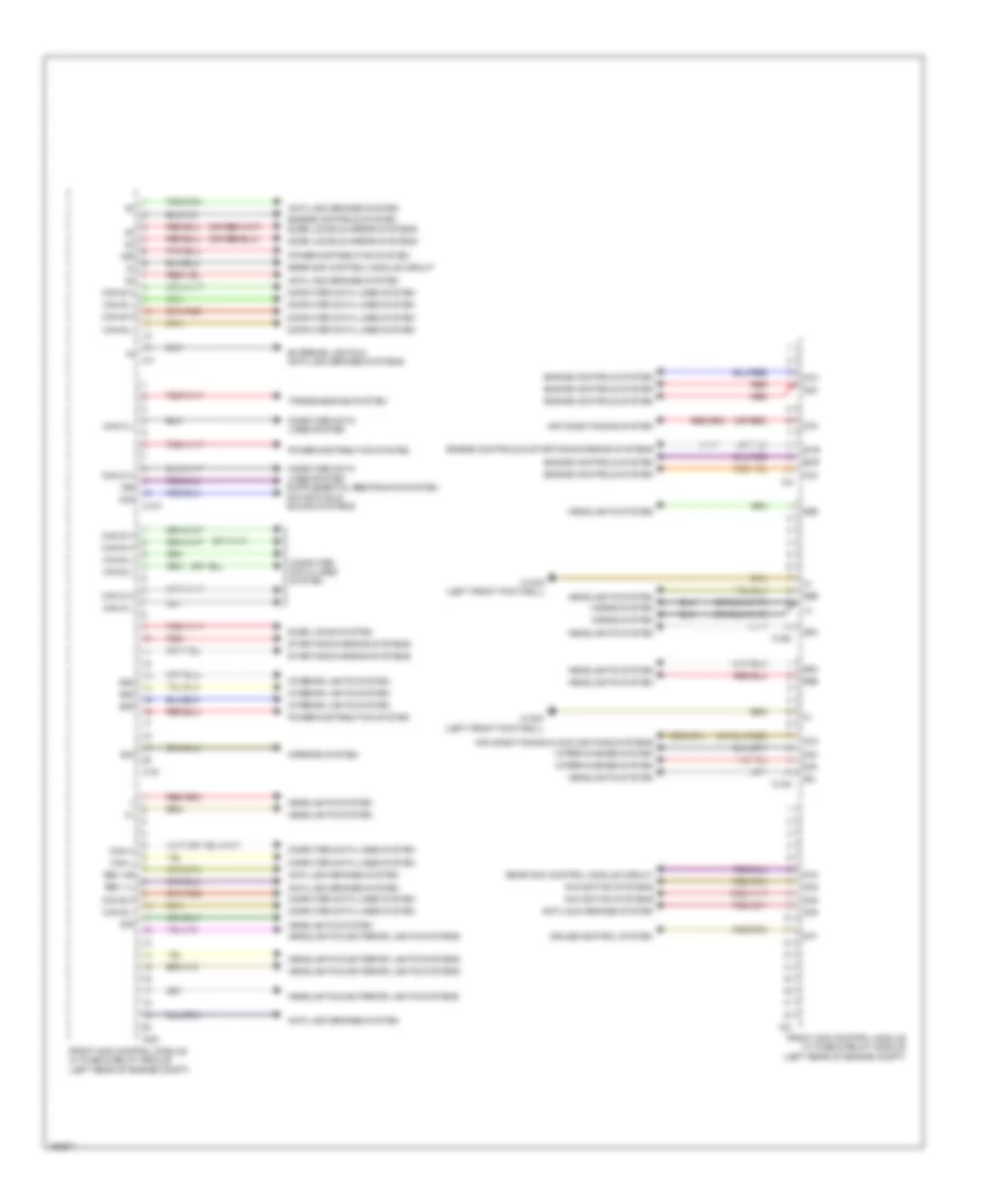
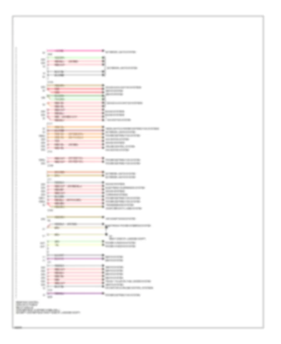
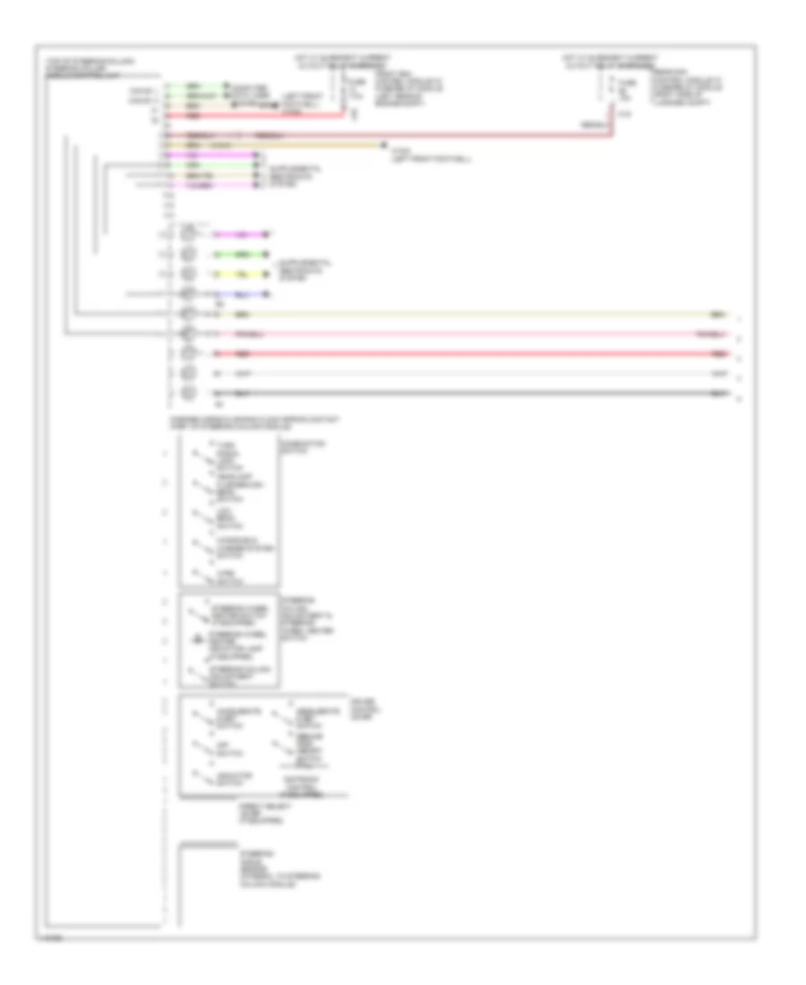
Driver"s Side SAM Control Module Wiring Diagram (1 of 2) for Mercedes-Benz E250 Bluetec 4Matic 2014
 https://portal-diagnostov.com/license.html
Automotive Electricians Portal FZCO
Automotive Electricians Portal FZCO
https://portal-diagnostov.com/license.html
https://portal-diagnostov.com/license.html
Automotive Electricians Portal FZCO
Automotive Electricians Portal FZCOList of elements for Driver"s Side SAM Control Module Wiring Diagram (1 of 2) for Mercedes-Benz E250 Bluetec 4Matic 2014:
- (+)
- (or red)
- 12s
- 12v
- 15r
- 30g
- 30z
- 49l
- 58d
- 58l
- 5v khd
- 87f
- 87m
- Air conditioning
- Air conditioning system
- Anst
- Anti-lock brakes system
- Bfs
- C11c
- C13d
- C16s
- C17c
- C18m
- C1m
- C20m
- C21m
- C3m
- C5c
- C6i
- C8s
- C9g
- Can b h
- Can b l
- Can e h
- Can e l
- Can-g h
- Can-g l
- Computer data lines system
- Electronic power steering system
- Engine controls & starting/charging systems
- Engine controls system
- Exterior lights system
- Front electrical prefuse box (right rear of engine compt)
- Front sam control module w/ fuse & relay module (left rear of engine compt)
- Fuse 100a
- Fuse 150a
- Gnd
- Headlights & exterior lights systems
- Headlights system
- Hot at all times
- Hot w/ quiescent current cutout relay energized
- Instrument cluster system
- Interior lights system
- Khd
- Lin 1
- Lin 2
- Lin b8
- Lwr
- Mg2
- Mr7
- Mrg2
- Ntc+
- Ntc-
- Pnk/red
- Power distribution system
- Red
- Rfl
- Sig
- Sig il
- Slp
- Sound systems
- Starting/charging system
- System
- Transmissions system
- W/ eco start/stop function
- W/o eco start/stop function
- W15/5 (left front footwell)
- Wiper/washer system
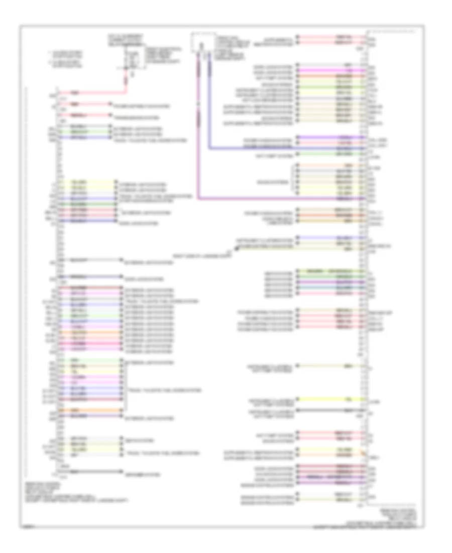
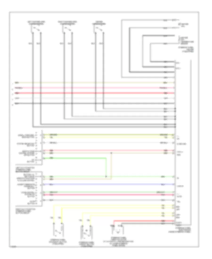
Driver"s Side SAM Control Module Wiring Diagram (2 of 2) for Mercedes-Benz E250 Bluetec 4Matic 2014
 https://portal-diagnostov.com/license.html
Automotive Electricians Portal FZCO
Automotive Electricians Portal FZCO
https://portal-diagnostov.com/license.html
https://portal-diagnostov.com/license.html
Automotive Electricians Portal FZCO
Automotive Electricians Portal FZCOList of elements for Driver"s Side SAM Control Module Wiring Diagram (2 of 2) for Mercedes-Benz E250 Bluetec 4Matic 2014:
- (+)
- (or red)
- 15r
- 30g
- 30z
- 55l
- 55r
- 56a
- 56b
- 58d
- 87f
- 87m
- Air conditioning & cooling fans systems
- Air conditioning system
- Anti-lock brakes system
- Bbv hr
- Bbv vl
- C10t
- C14m
- C15m
- C19i
- C22i
- C2i
- C4i
- C7i
- Can b h
- Can b l
- Can d h
- Can d l
- Can e h
- Can e l
- Can h
- Can l
- Computer data lines system
- Cruise control system
- Door locks & mirror systems
- Door locks system
- Ekp
- Engine controls & starting/charging systems
- Engine controls system
- Exterior lights & anti-lock brakes systems
- Front sam control module w/ fuse & relay module (left rear of engine compt)
- Headlights & exterior lights systems
- Headlights system
- Horns system
- Interior lights system
- Mirrors system
- Navigation systems
- Power distribution system
- Rear sam control module circuit
- Red
- Sig
- Starting/charging systems
- Str
- Transmissions system
- W15/5 (left front footwell)
- Wiper/washer system
Rear SAM Control Module Wiring Diagram (1 of 2) for Mercedes-Benz E250 Bluetec 4Matic 2014
 https://portal-diagnostov.com/license.html
Automotive Electricians Portal FZCO
Automotive Electricians Portal FZCO
https://portal-diagnostov.com/license.html
https://portal-diagnostov.com/license.html
Automotive Electricians Portal FZCO
Automotive Electricians Portal FZCOList of elements for Rear SAM Control Module Wiring Diagram (1 of 2) for Mercedes-Benz E250 Bluetec 4Matic 2014:
- (+)
- 15r(1)
- 30g
- 30r
- 31e
- 49l
- 49r
- 58d
- 58l
- 58r
- 87m
- Anti-lock brakes system
- Anti-theft system
- Bla
- Bsl-l
- Bsl-r
- C1h
- C1v
- C2g
- C2i
- C2v
- C3i
- C5h
- C6hd
- C8d
- C9i
- Can b h
- Can b l
- Computer data lines system
- Defogger system
- Door locks system
- Edw
- Engine controls systems
- Exterior lights system
- Front electrical prefuse box (right rear of engine compt)
- Front sam control module w/ fuse & relay module (left rear of c7i engine compt)
- Fuse 150a
- Gss hl
- Gss hm
- Gss hr
- Hall (+)
- Hall (-)
- Hall sig 1
- Hall sig2
- Hot w/ quiescent current cutout relay energized
- Ig1
- Instrument cluster & anti-theft systems
- Instrument cluster system
- Interior lights system
- Ism
- Lin
- Lin b4
- Navigation system
- Nsl-l
- Nsl-r
- Power distribution system
- Power windows system
- Rear sam control module w/ fuse & relay module (convertible: in spare wheelwell) (except convertible: right side of luggage compt)
- Red
- Rfl-l
- Rfl-r
- Rss gnd off
- Rss gnd on
- Rss off
- Rss on
- Seats system
- Sig
- Sig 90
- Sl/bl
- Sml
- Smr
- Sound systems
- Starting/charging system
- Stop function
- Tg l
- Tg r
- Transmissions system
- Trunk, tailgate, fuel doors system
- W/ eco start/ stop function
- W/o eco start/
- W7 (right side of luggage compt)
- Zv mot
- Zv sig
Rear SAM Control Module Wiring Diagram (2 of 2) for Mercedes-Benz E250 Bluetec 4Matic 2014
 https://portal-diagnostov.com/license.html
Automotive Electricians Portal FZCO
Automotive Electricians Portal FZCO
https://portal-diagnostov.com/license.html
https://portal-diagnostov.com/license.html
Automotive Electricians Portal FZCO
Automotive Electricians Portal FZCOList of elements for Rear SAM Control Module Wiring Diagram (2 of 2) for Mercedes-Benz E250 Bluetec 4Matic 2014:
- (+)
- (or red)
- 15r
- 15r(1)
- 15r(2)
- 30g
- Aag
- Air conditioning system
- C10r
- C11
- C11t
- C12i
- C13a
- C14i
- C15h
- C7i
- Computer data lines system
- Cruise control system
- Electronic power steering system
- Electronic suspension system
- Exterior lights system
- Headlights & power distribution systems
- Mot
- Navigation & cruise control systems
- Navigation system
- Power distribution system
- Power windows system
- Rear sam control module w/ fuse & relay module (convertible: in spare wheelwell) (except convertible: right side of luggage compt)
- Red
- Scr
- Seats system
- Sound & navigation systems
- Sound systems
- Transmissions system
- Trunk, tailgate, fuel doors system
- W7 (right side of luggage compt)
- Warning systems
COMPUTER DATA LINES
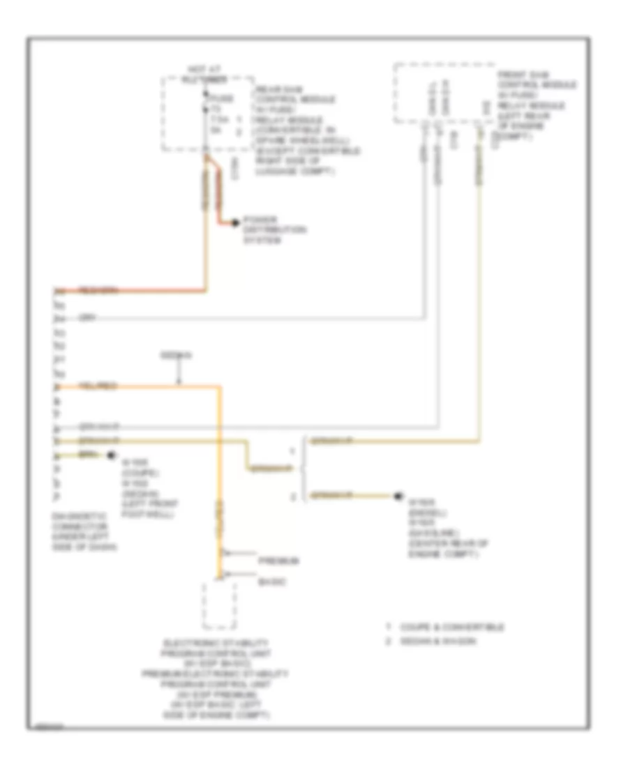
Data Link Connector Wiring Diagram for Mercedes-Benz E250 Bluetec 4Matic 2014
 https://portal-diagnostov.com/license.html
Automotive Electricians Portal FZCO
Automotive Electricians Portal FZCO
https://portal-diagnostov.com/license.html
https://portal-diagnostov.com/license.html
Automotive Electricians Portal FZCO
Automotive Electricians Portal FZCOList of elements for Data Link Connector Wiring Diagram for Mercedes-Benz E250 Bluetec 4Matic 2014:
- 31e
- Basic
- C15h
- C19i
- C22i
- Can d h
- Can d l
- Coupe & convertible
- Diagnostic connector (under left side of dash)
- Electronic stability program control unit (w/ esp basic) premium electronic stability program control unit (w/ esp premium) (w/ esp basic: left side of engine compt)
- Front sam control module w/ fuse/ relay module (left rear of engine compt)
- Fuse 7.5a 5a
- Hot at all times
- Power distribution system
- Premium
- Rear sam control module w/ fuse/ relay module (convertible: in spare wheelwell) (except convertible: right side of luggage compt)
- Sedan
- Sedan & wagon
- W15/5 (coupe) w15/2 (sedan) (left front footwell)
- W16/6 (diesel) w16/5 (gasoline) (center rear of engine compt)
High/Low Bus Wiring Diagram (1 of 6) for Mercedes-Benz E250 Bluetec 4Matic 2014
 https://portal-diagnostov.com/license.html
Automotive Electricians Portal FZCO
Automotive Electricians Portal FZCO
https://portal-diagnostov.com/license.html
https://portal-diagnostov.com/license.html
Automotive Electricians Portal FZCO
Automotive Electricians Portal FZCOList of elements for High/Low Bus Wiring Diagram (1 of 6) for Mercedes-Benz E250 Bluetec 4Matic 2014:
- 2.1l turbo diesel
- 3.0l turbo diesel
- 3.5l & 4.6l turbo
- Audio/comand control panel
- Audio/comand display
- Can-a h
- Can-a l
- Can-c h
- Can-c l
- Comand control unit
- Drive train can voltage distributor electrical connector
- Dvd player (w/ rear entertainment (dvd))
- Electronic selector lever module control module (base of shift lever assembly)
- Electronic transmission control unit (under front of center console)
- Fuel pump control unit (behind right quarterpanel)
- Fully integrated transmission control unit (in transmission)
- Intelligent servo module for direct select (if equipped) (bottom of transmission housing)
- Left rear display (w/ rear entertainment (dvd))
- Me-sfi (me) control unit (except 3.0l turbo diesel) cdi control unit (3.0l turbo diesel) (3.0l turbo diesel: in right front wheelwell) (3.5l: left side of engine) (4.6l turbo: top center rear of engine)
- Module for direct select
- Navigation module
- Radio
- Right rear display (w/ rear entertainment (dvd))
- Telematics can voltage distributor electrical connector
- Transmission oil auxiliary pump control unit (bottom of transmission)
- Tv tuner (analog/digital) (right side of luggage compt)
- W/ audio 20
- W/ comand
- W/ direct select
- W/ electronic transmission control
- W/ intelligent servo
- W/ navigation
- W/o direct select
- W/o electronic transmission control
- W/o intelligent servo
- W15/1 (right front footwell)
- W15/5 (left front footwell)
- X138/1-c1
- X18/35-c1
- X55/3-c9
- X55/4-c9
High/Low Bus Wiring Diagram (2 of 6) for Mercedes-Benz E250 Bluetec 4Matic 2014
 https://portal-diagnostov.com/license.html
Automotive Electricians Portal FZCO
Automotive Electricians Portal FZCO
https://portal-diagnostov.com/license.html
https://portal-diagnostov.com/license.html
Automotive Electricians Portal FZCO
Automotive Electricians Portal FZCOList of elements for High/Low Bus Wiring Diagram (2 of 6) for Mercedes-Benz E250 Bluetec 4Matic 2014:
- (left front footwell) w15/2
- C10
- C11
- C11c
- C12
- C13
- C19i
- C22i
- C7i
- Can-a h
- Can-a l
- Can-b h
- Can-b l
- Can-e h
- Can-e l
- Can-e1 h
- Can-e1 l
- Comand control unit (if equipped)
- Driver seat control unit (under driver front seat)
- Dynamic multicontour seat pneumatic pump (if equipped) (left side of luggage compt)
- Front sam control module w/ fuse/ relay module (left rear of engine compt)
- Left front door control unit
- Left front dynamic multicontour seat control unit (in left front seat back)
- Left rear door control unit
- Left vehicle floor interior can voltage distributor electrical connector
- Overhead control panel control unit
- Panoramic sliding roof control module (center front of roof)
- Radio (w/ audio 20 radio) radio w/ auto pilot system (w/ audio 50)
- Tailgate control unit (wagon) trunk lid control unit (sedan) (wagon: top of left "d" pillar) (sedan: center front of luggage compt)
- W/ audio 20 radio & radio 50
- W/ memory
- W/ panoramic sliding roof
- W/o audio 20 radio & radio 50
- W/o memory
- W/o panoramic sliding roof
- Wagon
- X204
- X35/3-c1
- X55/3-c1
- X8/45-c1
High/Low Bus Wiring Diagram (3 of 6) for Mercedes-Benz E250 Bluetec 4Matic 2014
 https://portal-diagnostov.com/license.html
Automotive Electricians Portal FZCO
Automotive Electricians Portal FZCO
https://portal-diagnostov.com/license.html
https://portal-diagnostov.com/license.html
Automotive Electricians Portal FZCO
Automotive Electricians Portal FZCOList of elements for High/Low Bus Wiring Diagram (3 of 6) for Mercedes-Benz E250 Bluetec 4Matic 2014:
- C10
- C11
- C110
- C12
- C13
- C9i
- Can b h
- Can b l
- Can-b h
- Can-b l
- Can-e h
- Can-e l
- Can-e1 h
- Can-e1 l
- Collision prevention assist controller unit (if equipped) (behind right side of front bumper)
- Front passenger seat control unit (under front passenger seat)
- Keyless go control unit (if equipped) (right side of luggage compt)
- Left front reversible emergency tensioning retractor (if equipped) (base of left "b" pillar)
- Me-sfi (me) control unit (except 3.0l turbo diesel) cdi control unit (3.0l turbo diesel) (3.0l turbo diesel: in right front wheelwell) (3.5l: left side of engine) (4.6l turbo: top center rear of engine)
- Rear sam control module w/ fuse/relay module (right side of luggage compt)
- Rear seat heaters control unit (if equipped) (right side of luggage compt)
- Right front door control unit
- Right front dynamic multicontour seat control unit (in right front seat back)
- Right rear door control unit
- Right vehicle floor interior can voltage distributor electrical connector
- Special purpose vehicle multi-function control unit (w/ taxi electrical system) (center front of luggage compt)
- Stationary heater unit (if equipped) (behind right side of front bumper)
- Trailer recognition control unit (if equipped) (right side of luggage compt)
- Vehicle floor chassis can voltage distributor electrical connector
- W/ active park assist
- W/ memory
- W/o active park assist
- W/o memory
- W15/2 (left front footwell)
- X26/38-c1
- X26/38-c2
- X35/4-c1
- X55/3
High/Low Bus Wiring Diagram (4 of 6) for Mercedes-Benz E250 Bluetec 4Matic 2014
 https://portal-diagnostov.com/license.html
Automotive Electricians Portal FZCO
Automotive Electricians Portal FZCO
https://portal-diagnostov.com/license.html
https://portal-diagnostov.com/license.html
Automotive Electricians Portal FZCO
Automotive Electricians Portal FZCOList of elements for High/Low Bus Wiring Diagram (4 of 6) for Mercedes-Benz E250 Bluetec 4Matic 2014:
- Airmatic control unit (right front upper footwell)
- Automatic air conditioning control & operating unit (2 & 3 zones thermatic)
- Can e1 h
- Can e1 l
- Can-b h
- Can-b l
- Can-e h
- Can-e l
- Can-e1 h
- Can-e1 l
- Can-h h
- Can-h l
- Distronic electronic controller unit (w/ distronic plus) (behind center of front grille)
- Electronic ignition switch control unit
- Electronic stability program control unit (left side of engine compt)
- Except hybrid
- Hybrid
- Instrument cluster
- Left rear bumper intelligent radar sensor (behind left end of rear bumper)
- Night vision assist control unit (if equipped) (right kick panel)
- Premium electronic stability program control unit (w/ esp premium)
- Radar sensor control unit (w/ distronic plus, blind spot assist & active lane keeping assist) (right front upper footwell)
- Rear axle electronic level control unit (right front upper footwell)
- Regenerative braking system control unit
- Right front reversible emergency tensioning retractor (if equipped) (base of right "b" pillar)
- Right rear bumper intelligent radar sensor (behind right end of rear bumper)
- Steering column module control unit (top of steering column)
- Steering wheel heater control unit (if equipped) (underside of steering column)
- Vehicle dynamics can voltage distributor electrical connector
- W/ esp basic
- W/ esp premium
- W/ hydraulics
- W/o hydraulics
- X172/2
- Yaw rate, lateral & longitudinal acceleration sensor (w/ esp premium) (under front passenger's seat)
High/Low Bus Wiring Diagram (5 of 6) for Mercedes-Benz E250 Bluetec 4Matic 2014
 https://portal-diagnostov.com/license.html
Automotive Electricians Portal FZCO
Automotive Electricians Portal FZCO
https://portal-diagnostov.com/license.html
https://portal-diagnostov.com/license.html
Automotive Electricians Portal FZCO
Automotive Electricians Portal FZCOList of elements for High/Low Bus Wiring Diagram (5 of 6) for Mercedes-Benz E250 Bluetec 4Matic 2014:
- 2.1l turbo diesel
- Battery management system control unit (on contactor assembly)
- Can-i h
- Can-i l
- Can-l h
- Can-l l
- Cdi control unit (in right front wheelwell)
- Electric refrigerant compressor (lower left front of engine)
- Except 2.1l turbo diesel
- Hybrid can potential distributor electrical connector
- Left nox sensor control unit
- Me-sfi (me) control unit (3.5l & 3.5l hybrid) (left side of engine)
- Me-sfi (me) control unit (3.5l: left side of engine) (4.6l turbo: top center rear of engine)
- Nitrogen oxides control unit downstream of diesel particulate filter (3.0l turbo diesel) (under right front of vehicle)
- Nitrogen oxides control unit downstream of scr catalytic converter (near scr catalytic converter)
- Pnk
- Potential distributor electrical connector (can i)
- Power electronics control unit (bottom right side of engine)
- Right nox sensor control unit
- W15/1 (right front footwell)
- W18 (under driver's seat)
- X18/7-c2
- X86/1-c1a
- X86/1-c2
- X86/3-c1
- X86/4-c1
High/Low Bus Wiring Diagram (6 of 6) for Mercedes-Benz E250 Bluetec 4Matic 2014
 https://portal-diagnostov.com/license.html
Automotive Electricians Portal FZCO
Automotive Electricians Portal FZCO
https://portal-diagnostov.com/license.html
https://portal-diagnostov.com/license.html
Automotive Electricians Portal FZCO
Automotive Electricians Portal FZCOList of elements for High/Low Bus Wiring Diagram (6 of 6) for Mercedes-Benz E250 Bluetec 4Matic 2014:
- 18m
- 19i
- 22i
- 360 degree camera control unit
- Backup camera (right center rear of luggage compt lid)
- C10
- C11
- C12
- C13
- Can e2 h
- Can e2 l
- Chassis gateway control unit (if equipped) (right front upper footwell)
- Electrical power steering control unit (on steering rack assembly)
- Front sam control unit w/ fuse & relay module (left rear of engine compt)
- Instrument cluster
- Multifunction camera (integral to interior rearview mirror base assembly)
- Parking system control unit (if equipped)
- Tire pressure monitor control unit (if equipped) (above right side of rear axle)
- Vehicle floor chassis can 2 potential distributor electrical connector
- W/ 360 degree camera
- W/ backup camera
- Wagon
- X1/60-c1
- X8/45-c3
- X83/11-c2
COOLING FAN
Cooling Fan Wiring Diagram for Mercedes-Benz E250 Bluetec 4Matic 2014
 https://portal-diagnostov.com/license.html
Automotive Electricians Portal FZCO
Automotive Electricians Portal FZCO
https://portal-diagnostov.com/license.html
https://portal-diagnostov.com/license.html
Automotive Electricians Portal FZCO
Automotive Electricians Portal FZCOList of elements for Cooling Fan Wiring Diagram for Mercedes-Benz E250 Bluetec 4Matic 2014:
- 2.1l turbo diesel
- C14m
- C18m
- C21m
- C22i
- C4i
- Can b h
- Can b l
- Can-b h
- Can-b l
- Combustion engine & air conditioning w/ integrated control fan motor (behind radiator)
- Computer data lines system
- Coolant circulation pump (w/ 2-zone thermatic & 3-zone thermotronic) (right front of engine compt)
- Coolant temperature sensor (rear of left cylinder bank)
- Engine controls system
- Except 2.1l turbo diesel
- Front electrical prefuse box (right rear of engine compt)
- Front sam control module w/ fuse/ relay module (left rear of engine compt)
- Fuse 100a
- Fuse 15a
- Gnd nwg m2
- Hot at all times
- Hot w/ engine circuit 87 relay energized
- Interior temperature sensor w/ integrated fan
- Lpv
- Lues
- Me-sfi (me control unit) (except 2.1l turbo diesel) cdi control module (2.1l turbo diesel) (3.5l: left side of engine) (4.6l turbo: top center rear of engine) (2.1l turbo diesel: in right front wheelwell)
- Mr4
- Overhead control panel control module (w/o tilting/sliding roof)
- Purge control valve (except 2.1l turbo diesel) (left front of engine compt)
- Red
- Refrigerant pressure sensor (lower left side of radiator on refrigerant line)
- Sig
- Solid state
- Tmot
- W/ eco start/ stop function
- W/o eco start/ stop function
- W15/5 (left front footwell)
- W2 (right side of engine compt)
- W2 (w/ 800 w fan motor) (right side of engine compt)
- W9 (w/ 650 w fan motor) (behind left headlight unit)
- X25/2-c1
CRUISE CONTROL
Cruise Control Wiring Diagram for Mercedes-Benz E250 Bluetec 4Matic 2014
 https://portal-diagnostov.com/license.html
Automotive Electricians Portal FZCO
Automotive Electricians Portal FZCO
https://portal-diagnostov.com/license.html
https://portal-diagnostov.com/license.html
Automotive Electricians Portal FZCO
Automotive Electricians Portal FZCOList of elements for Cruise Control Wiring Diagram for Mercedes-Benz E250 Bluetec 4Matic 2014:
- (-)
- (right side of engine compt) w2
- (w/ distronic plus & active blind spot assist) front long range radar sensor
- +5v
- Accelerate & set switch
- Accelerator pedal sensor (on accelerator pedal assembly)
- C12i
- C14i
- C2i
- C4i
- C5c
- Can b h
- Can b l
- Can ch
- Can e h
- Can e l
- Can e1 h
- Can e1 l
- Can s1 h
- Can s1 l
- Can s2 h
- Can s2 l
- Cdi control unit
- Center rear bumper radar sensor (w/ rear-end collision warning & protection system)
- Chassis gateway control unit (right front upper footwell)
- Computer data lines system
- Cruise control lever
- Decelerate & set switch
- Distronic control (if equipped)
- Fr a bm
- Fr a bp
- Fr3 bm rdu
- Fr3 bp rdu
- Front sam control module w/ fuse & relay module (left rear of engine compt)
- Fully integrated transmission control unit (in transmission)
- Fuse 5a
- Fuse 7.5a
- Gnd
- Hot at all times
- Hot w/ chassis circuit 87 relay energized
- Hot w/ circuit 15 relay energized
- Hot w/ circuit 15r relay 2 energized
- Hot w/ secondary air injection relay energized
- Indicator switch
- Instrument cluster
- Left front bumper distronic sensor (behind left side of front bumper)
- Left rear bumper radar sensor (w/ active blind spot assist) (behind left end of rear bumper)
- M (-)
- Memory switch resume from
- Off switch
- Output shaft rpm sensor
- Pedestrian protection
- Pnk
- Poti sig
- Power distribution system
- Radar sensors control unit (right front upper footwell)
- Rear sam control module w/ fuse & relay module (right side of luggage compt)
- Red
- Right front bumper distronic sensor (distronic plus) (behind right side of front bumper)
- Right rear bumper radar sensor (w/ active blind spot assist) (behind right end of rear bumper)
- Sp1m
- Sp1s
- Sp2m
- Sp2s
- Steering column module (top of steering column)
- Throttle valve actuator (top front of engine)
- U pwg
- W/ active park assist &
- W/ active park assist w/o pedestrian protection
- W/ pedestrian protection
- W/o active park assist
- W15/1 (right front footwell)
- W15/5 (left front footwell)
- W16/6 (center rear of engine compt)
- W2 (right side of engine compt)
- W7/8 (right (side of luggage compt)
- X172/2-c1
- X26/38-c1
- X26/38-c2
- X26/38-c3
- X26/38-c4
DEFOGGERS
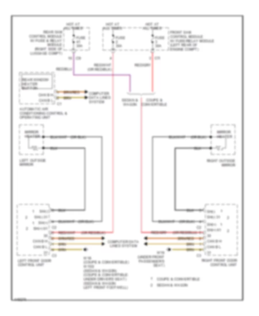
Heated Mirrors Wiring Diagram for Mercedes-Benz E250 Bluetec 4Matic 2014
 https://portal-diagnostov.com/license.html
Automotive Electricians Portal FZCO
Automotive Electricians Portal FZCO
https://portal-diagnostov.com/license.html
https://portal-diagnostov.com/license.html
Automotive Electricians Portal FZCO
Automotive Electricians Portal FZCOList of elements for Heated Mirrors Wiring Diagram for Mercedes-Benz E250 Bluetec 4Matic 2014:
- Automatic air conditioning control & operating unit
- C2 sh(+) 61
- C3i
- C7i
- Can b h
- Can b l
- Computer data lines system
- Coupe & convertible
- Front sam control module w/ fuse/relay module (left rear of engine compt)
- Fuse 30a
- Hot at all times
- Left front door control unit
- Left outside mirror
- Mirror heater
- Rear sam control module w/ fuse & relay module (right side of luggage compt)
- Rear window heater button
- Right front door control unit
- Right outside mirror
- Sedan & wagon
- Sh(+)
- Sh(+) 61
- Sh(-)
- Sh(-) 31
- W18 (coupe & convertible) w15/2 (sedan & wagon) (coupe & convertible: under driver's seat) (sedan & wagon: left front footwell)
- W19 (under front passenger's seat)
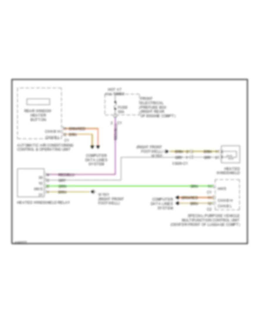
Heated Windshield Wiring Diagram for Mercedes-Benz E250 Bluetec 4Matic 2014
 https://portal-diagnostov.com/license.html
Automotive Electricians Portal FZCO
Automotive Electricians Portal FZCO
https://portal-diagnostov.com/license.html
https://portal-diagnostov.com/license.html
Automotive Electricians Portal FZCO
Automotive Electricians Portal FZCOList of elements for Heated Windshield Wiring Diagram for Mercedes-Benz E250 Bluetec 4Matic 2014:
- (right front footwell) w15/1
- Automatic air conditioning control & operating unit
- Can b h
- Can b l
- Computer data lines system
- Front electrical prefuse box (right rear of engine compt)
- Fuse 50a
- Heated windshield
- Heated windshield relay
- Hot at all times
- Hws
- Rear window heater button
- Special-purpose vehicle multifunction control unit (center front of luggage compt)
- W15/1 (right front footwell)
- X92/6-c1
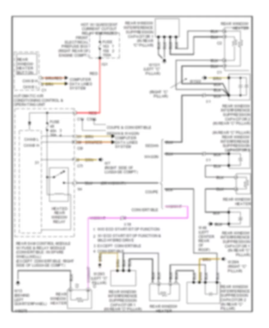
Rear Defogger Wiring Diagram for Mercedes-Benz E250 Bluetec 4Matic 2014
 https://portal-diagnostov.com/license.html
Automotive Electricians Portal FZCO
Automotive Electricians Portal FZCO
https://portal-diagnostov.com/license.html
https://portal-diagnostov.com/license.html
Automotive Electricians Portal FZCO
Automotive Electricians Portal FZCOList of elements for Rear Defogger Wiring Diagram for Mercedes-Benz E250 Bluetec 4Matic 2014:
- (in rear "c" pillar) rear window interference suppression capacitor 2
- (right "c" pillar)
- Automatic air conditioning control & operating unit
- C1v
- C30g
- C7i
- C9i
- Can-b h
- Can-b l
- Computer data lines system
- Convertible
- Coupe
- Coupe & convertible
- Except convertible
- Front electrical prefuse box (right rear of engine compt)
- Fuse 150a
- Fuse 40a 30a
- Heated rear window relay
- Hot w/ quiescent current cutout relay energized
- Ig1
- Mild hybrid drive
- Rear sam control module w/ fuse & relay module (convertible: in spare whellwell) (except convertible: right side of luggage compt)
- Rear window heater
- Rear window heater button
- Rear window interference suppression capacitor 1 (in rear "c" pillar)
- Rear window interference suppression capacitor 2 (in rear "c" pillar)
- Red
- Sedan
- Sedan & wagon
- W/ eco start/stop function &
- W/o eco start/stop function
- W13 (behind left quarterpanel)
- W13/1 (left "c" pillar)
- W13/2
- W29/3 (left "c" pillar)
- W29/4 (right "c" pillar)
- W48 (left center rear of roof)
- W7 (right side of luggage compt)
- Wagon
- X19
ELECTRONIC POWER STEERING
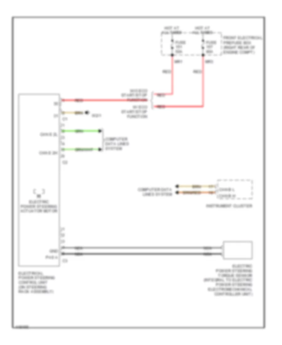
Electronic Power Steering Wiring Diagram for Mercedes-Benz E250 Bluetec 4Matic 2014
 https://portal-diagnostov.com/license.html
Automotive Electricians Portal FZCO
Automotive Electricians Portal FZCO
https://portal-diagnostov.com/license.html
https://portal-diagnostov.com/license.html
Automotive Electricians Portal FZCO
Automotive Electricians Portal FZCOList of elements for Electronic Power Steering Wiring Diagram for Mercedes-Benz E250 Bluetec 4Matic 2014:
- Can b h
- Can b l
- Can e 2h
- Can e 2l
- Computer data lines system
- Electric power steering actuator motor
- Electric power steering torque sensor (integral to electric power steering electromechanical controller unit)
- Electrical power steering control unit (on steering rack assembly)
- Front electrical
- Fuse 50a
- Fuse 80a
- Gnd
- Hot at all times
- Instrument cluster
- Mr1
- Mr3
- Nca
- Pas a
- Prefuse box (right rear of engine compt)
- Red
- W/ eco start/stop function
- W/o eco start/stop function
- W2/1
Power Steering Column Wiring Diagram (1 of 2) for Mercedes-Benz E250 Bluetec 4Matic 2014
 https://portal-diagnostov.com/license.html
Automotive Electricians Portal FZCO
Automotive Electricians Portal FZCO
https://portal-diagnostov.com/license.html
https://portal-diagnostov.com/license.html
Automotive Electricians Portal FZCO
Automotive Electricians Portal FZCOList of elements for Power Steering Column Wiring Diagram (1 of 2) for Mercedes-Benz E250 Bluetec 4Matic 2014:
- (left front footwell) w15/5
- (top of steering column) steering column module control unit
- Accelerate & set switch
- C12i
- C5c
- Can e1 h
- Can e1 l
- Combination switch
- Computer data lines system
- Cruise control lever
- Decelerate & set switch
- Direct select lever (if equipped)
- Distronic control (if equipped)
- Fanfare horns & air bag clock spring contact (part of steering column module)
- Front sam control module w/ fuse/relay module (left rear of engine compt)
- Fuse 10a
- Fuse 7.5a
- Headlamp flasher/high beam switch
- Hot w/ quiescent current cutout relay energized
- Indicator switch
- Low beam switch
- Off switch
- Rear sam control module w/ fuse/relay module (right side of luggage compt)
- Red
- Resume from memory switch
- Steering angle sensor (integral to steering column module)
- Steering column adjustment & steering wheel heater switch
- Steering column adjustment switch
- Steering wheel heater indicator lamp (if equipped)
- Steering wheel heater switch (if equipped)
- Turn signal lamp switch
- W15/2 (left front footwell)
- Windshield washer system switch
- Wipe switch
- X18-c1
Power Steering Column Wiring Diagram (2 of 2) for Mercedes-Benz E250 Bluetec 4Matic 2014
 https://portal-diagnostov.com/license.html
Automotive Electricians Portal FZCO
Automotive Electricians Portal FZCO
https://portal-diagnostov.com/license.html
https://portal-diagnostov.com/license.html
Automotive Electricians Portal FZCO
Automotive Electricians Portal FZCOList of elements for Power Steering Column Wiring Diagram (2 of 2) for Mercedes-Benz E250 Bluetec 4Matic 2014:
- +, -
- Accept/terminate phone call button
- Aldw+
- Aldw-
- Back & voice control system off button
- Button + & - setting of specific functions & volume control
- Center horns button
- Gnd
- Heater coil
- Heater coil temperature sensor
- Left fanfare horn system button
- Left multi-function steering wheel button group
- Lsp+
- Lsp-
- Mute
- Mute button
- Nca
- Ntc +
- Ntc -
- Ok button
- Pnk
- R, return
- Red
- Right fanfare horn system button
- Right multi-function steering wheel button group
- Scroll forward/ back button
- Steering wheel downshift button (if equipped)
- Steering wheel electronics (inside steering wheel)
- Steering wheel heater (if equipped)
- Steering wheel upshift button (if equipped)
- Steering wheel vibration motor (w/ automatic lane recognition) (in lower steering wheel spoke)
- System selection button
- Tel
- U-mfl-r
- U-mll-l
- Voice control system on button
ELECTRONIC SUSPENSION
Airmatic Control Wiring Diagram (1 of 2) for Mercedes-Benz E250 Bluetec 4Matic 2014
 https://portal-diagnostov.com/license.html
Automotive Electricians Portal FZCO
Automotive Electricians Portal FZCO
https://portal-diagnostov.com/license.html
https://portal-diagnostov.com/license.html
Automotive Electricians Portal FZCO
Automotive Electricians Portal FZCOList of elements for Airmatic Control Wiring Diagram (1 of 2) for Mercedes-Benz E250 Bluetec 4Matic 2014:
- (behind left side of rear bumper) (sedan & wagon) airmatic valve unit
- (left rear wheelwell)
- +5v
- 30g
- Adaptive damping system control unit (coupe & convertible) airmatic control unit (sedan & wagon) (sedan & wagon: right front upper footwell)
- Air compressor motor
- Airmatic compressor (sedan & wagon) (under left rear of vehicle)
- Airmatic pressure reduction valve
- Ans/ablas sig
- C12i
- C15h
- Central reservoir filling valve
- Coupe & convertible
- Ds zent sp gnd
- Ds zent sp sig
- Ds zent sp vsg
- Fb hal niv sig
- Fb har niv sig
- Fb val niv sig
- Fb versg
- Fb war niv sig
- Fuse 15a
- Gnd
- H side
- Hot w/ quiscent current cutout relay energized
- L side
- Left front level control valve
- Left rear axle damping valve unit (on left rear shock absorber assembly)
- Left rear body lateral acceleration sensor (left front of luggage compt)
- Left rear level control valve
- Left rear level sensor
- Nca
- Pnk/red
- Pressure sensor
- Rear sam control module w/ fuse & relay module (convertible: in spare wheelwell) (except convertible: right side of luggage compt)
- Right front level control valve
- Right rear axle damping valve unit (on right rear shock absorber assembly)
- Right rear level valve
- Rkps
- Rkpv
- Sedan & wagon
- Sig
- Vkps
- Vkpv
- W15/1 (sedan & wagon) (right front footwell)
- W15/7 (coupe & convertible) (right front footwell)
- W6/4 (behind left side of rear bumper)
- X62/32-c1
- X62/32-c3
- X62/33-c1
- X62/33-c3
Airmatic Control Wiring Diagram (2 of 2) for Mercedes-Benz E250 Bluetec 4Matic 2014
 https://portal-diagnostov.com/license.html
Automotive Electricians Portal FZCO
Automotive Electricians Portal FZCO
https://portal-diagnostov.com/license.html
https://portal-diagnostov.com/license.html
Automotive Electricians Portal FZCO
Automotive Electricians Portal FZCOList of elements for Airmatic Control Wiring Diagram (2 of 2) for Mercedes-Benz E250 Bluetec 4Matic 2014:
- (or pnk/red)
- (right rear wheelwell)
- +5v
- Adaptive damping system control unit (coupe & convertible) airmatic control unit (sedan & wagon) (sedan & wagon: right front upper footwell)
- Airmatic relay (sedan & wagon) (left rear of luggage compt)
- Can
- Can-e h
- Can-e l
- Computer data lines system
- Coupe & convertible
- Front electrical prefuse box (sedan & wagon) (right rear of engine compt)
- Fuse 60a
- Gnd
- H side
- Hot at all times
- L side
- Left front axle damping valve unit (on left front shock absorber assembly)
- Left front body lateral acceleration sensor (engine compt, on left front shock tower)
- Left front level sensor (left front wheelwell)
- Nca
- Pnk/red
- Red
- Right front axle damping valve unit (on right front shock absorber assembly)
- Right front body lateral acceleration sensor (engine compt, on right front shock tower)
- Right front level sensor (right front wheelwell)
- Right rear level sensor
- Sedan & wagon
- Sig
- W/ eco start/stop function
- W/o eco start/stop function
- X62/33-c1
- X62/33-c3
- X62/6-c2
- X62/7
- X62/7-c2
Electronic Level Control Wiring Diagram for Mercedes-Benz E250 Bluetec 4Matic 2014
 https://portal-diagnostov.com/license.html
Automotive Electricians Portal FZCO
Automotive Electricians Portal FZCO
https://portal-diagnostov.com/license.html
https://portal-diagnostov.com/license.html
Automotive Electricians Portal FZCO
Automotive Electricians Portal FZCOList of elements for Electronic Level Control Wiring Diagram for Mercedes-Benz E250 Bluetec 4Matic 2014:
- (+)
- (-)
- (left rear of luggage compt) airmatic relay
- 15h
- 30g
- Ablv
- Air compressor motor
- Airmatic compressor (under left rear of vehicle)
- Airmatic pressure reduction valve
- Can e1 h
- Can e1 l
- Computer data lines system
- Electronic level control valve (behind left side of rear bumper)
- Front electrical prefuse box (right rear of engine compt)
- Fuse 15a
- Fuse 60a
- Hot at all times
- Hot w/ circuit 15r relay 2 energized
- Left rear level control valve
- Left rear level sensor (left rear wheelwell)
- Nv-ventil
- Rear axle electronic level control unit (right front upper footwell)
- Rear sam control module w/ fuse & relay module (right side of luggage compt)
- Red
- Right rear level control valve
- Right rear level sensor (right rear wheelwell)
- Sig
- W/ eco start/stop function
- W/o eco start/stop function
- W15/1 (right front footwell)
- W6/4 (behind left side of rear bumper)
- X62/32 c3
- X62/33 c3
ENGINE ACCESSORIES
Stationary Heater Wiring Diagram for Mercedes-Benz E250 Bluetec 4Matic 2014
 https://portal-diagnostov.com/license.html
Automotive Electricians Portal FZCO
Automotive Electricians Portal FZCO
https://portal-diagnostov.com/license.html
https://portal-diagnostov.com/license.html
Automotive Electricians Portal FZCO
Automotive Electricians Portal FZCOList of elements for Stationary Heater Wiring Diagram for Mercedes-Benz E250 Bluetec 4Matic 2014:
- (right rear of luggage compt) stationary heater radio remote control receiver
- 20a
- 30g
- Ant
- C116
- C11c
- C15h
- C17c
- C22i
- Can b h
- Can b l
- Combustion air blower
- Computer data lines system
- Early production
- Except hybrid
- Front sam control unit w/fuse & relay module (left rear of engine compt)
- Fuel preheating system heating element
- Fuse 20a
- Fuse 7.5a
- Glow plug flame monitor unit
- Heater control unit
- Hot at all times
- Hybrid
- Interior fuse box
- Late production
- Lin 1
- Mobile phone & stationary heater radio remote control antenna splitter (left side of luggage compt floor)
- Multi-function antenna
- Nca
- Rear sam control module w/fuse/ relay module (right side of luggage compt)
- Sig
- Stationary heater button
- Stationary heater fuel pump (under right rear of vehicle)
- Stationary heater fuse
- Stationary heater switchover valve (part of stationary heater unit)
- Stationary heater unit (part of stationary heater unit)
- Switchover valve
- Temperature sensor
- Tes
- Thermal fuse
- Upper control panel control unit
- W/ mobile phone
- W/o mobile phone
- W15/7 (right front footwell)
- W18 (under driver's seat)
- W19 (under front passenger's seat)
- W2 (right side of engine compt)
- X18-c4
- X62/33-c2
ENGINE PERFORMANCE
2.1L TURBO DIESEL
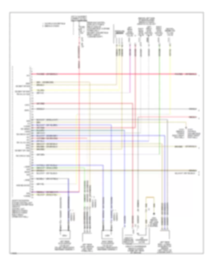
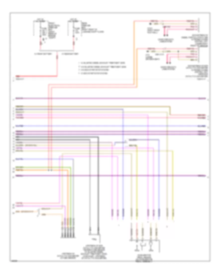
2.1L Turbo Diesel, Engine Performance Wiring Diagram (1 of 10) for Mercedes-Benz E250 Bluetec 4Matic 2014
 https://portal-diagnostov.com/license.html
Automotive Electricians Portal FZCO
Automotive Electricians Portal FZCO
https://portal-diagnostov.com/license.html
https://portal-diagnostov.com/license.html
Automotive Electricians Portal FZCO
Automotive Electricians Portal FZCOList of elements for 2.1L Turbo Diesel, Engine Performance Wiring Diagram (1 of 10) for Mercedes-Benz E250 Bluetec 4Matic 2014:
- (+)
- (-)
- 30z
- 87m
- 87m2
- Air conditioning system
- C16s
- C18m
- C3m
- C4i
- C6i
- Can c h
- Can c l
- Can e1 h
- Can e1 l
- Can i h
- Can i l
- Cdi control module (in right front wheelwell)
- Computer data lines system
- Crash
- Crash in kup1
- Differential pressure sensor (dpf) (w/ diesel particulate filter) (right rear of engine)
- Ekp e a nls1s
- Engine circuit relay
- Front electrical prefuse box (right rear of engine compt)
- Front sam control module w/ fuse/relay module (left rear of engine compt)
- Fuse 150a
- Fuse 15a
- Fuse 20a
- Fuse 7.5a
- Hot at all times
- Hot w/ chassis circuit 87 relay energized
- Kpis
- Lscp1
- Lsvg1
- Lsvn1
- Lues
- Mr7
- Nca
- O r shut
- Pnk
- Pnk/red
- Radiator shutters actuator (if equipped) (top right rear of radiator)
- Red
- Sig
- Sp1m
- Sp1s
- Sp2m
- Sp2m sp1m u pwg
- Sp2s
- Sp2s lsh1
- Starter circuit 50 relay
- Starting/charging system
- Str
- Str lues f
- U pwg
- W/ eco start/stop system
- W/o eco start/stop system
- W16/6 (center rear of engine compt)
- X25/2-c1
- X26
- X26-c1
- X86/1-c1b
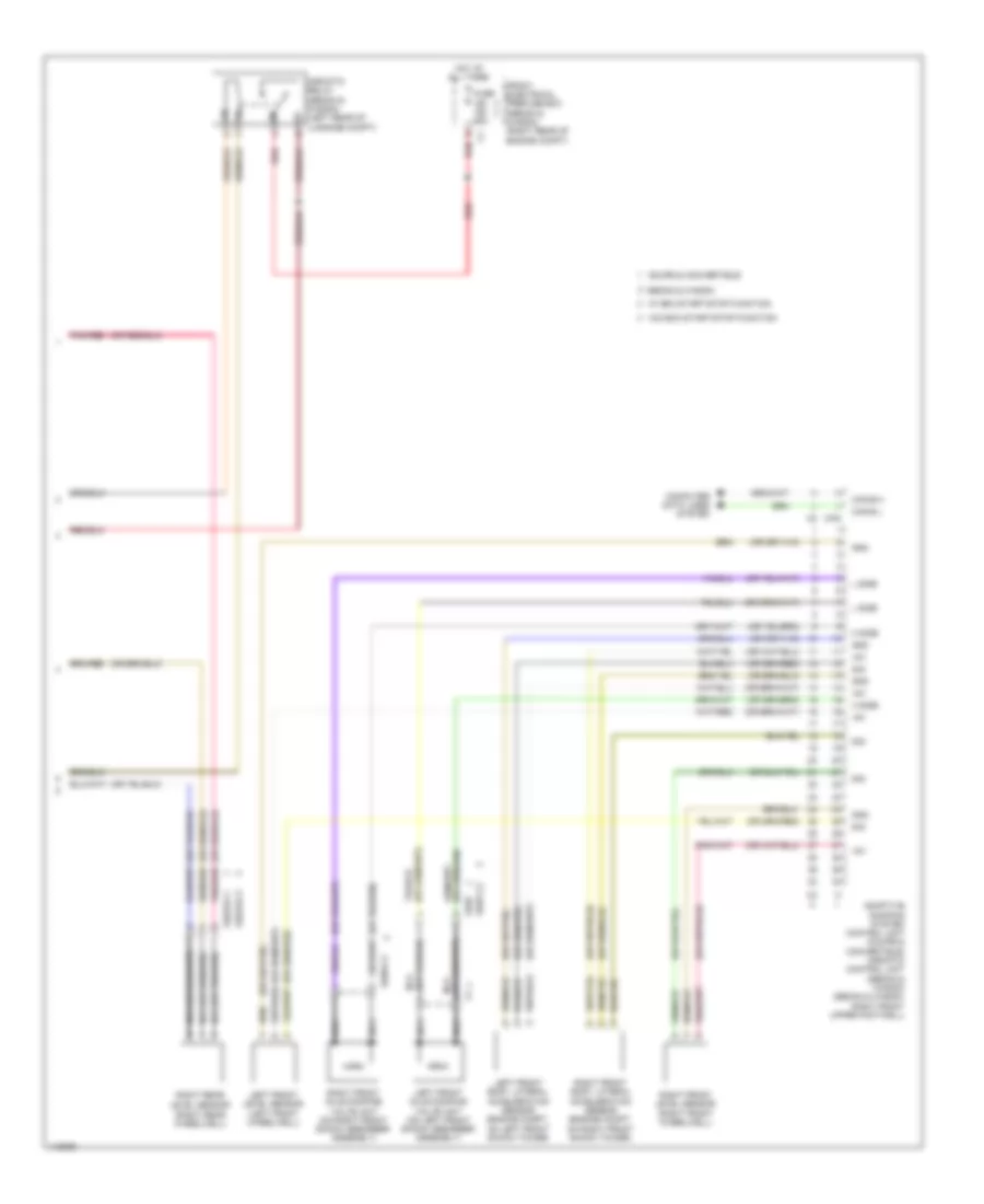
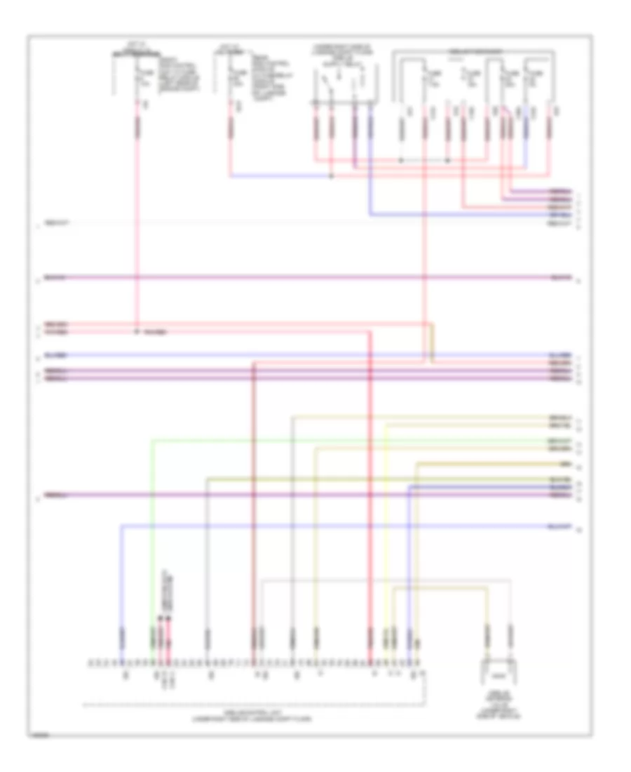
2.1L Turbo Diesel, Engine Performance Wiring Diagram (2 of 10) for Mercedes-Benz E250 Bluetec 4Matic 2014
 https://portal-diagnostov.com/license.html
Automotive Electricians Portal FZCO
Automotive Electricians Portal FZCO
https://portal-diagnostov.com/license.html
https://portal-diagnostov.com/license.html
Automotive Electricians Portal FZCO
Automotive Electricians Portal FZCOList of elements for 2.1L Turbo Diesel, Engine Performance Wiring Diagram (2 of 10) for Mercedes-Benz E250 Bluetec 4Matic 2014:
- C2v
- C3i
- C7i
- C9i
- California
- Except california
- Fuel pump relay
- Fuse 25a
- Heat exchanger shutoff valve
- Left fuel level indicator sensor (in left side of fuel tank)
- Left switchable engine mount (left bottom rear side of engine compt)
- Nca
- Pnk/red
- Rear sam control module w/ fuse/ relay module (right side of luggage compt)
- Red
- Right fuel level indicator sensor (in right side of fuel tank)
- Right switchable engine mount (right bottom rear side of engine compt)
- Tg l
- Tg r
- W7 (right side of luggage compt)
- X36/2-c1
- X36/3-c1
- X36/3-c2
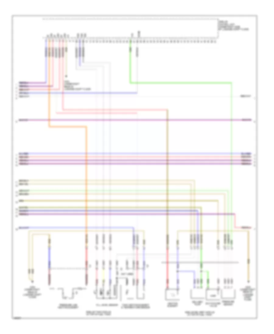
2.1L Turbo Diesel, Engine Performance Wiring Diagram (3 of 10) for Mercedes-Benz E250 Bluetec 4Matic 2014
 https://portal-diagnostov.com/license.html
Automotive Electricians Portal FZCO
Automotive Electricians Portal FZCO
https://portal-diagnostov.com/license.html
https://portal-diagnostov.com/license.html
Automotive Electricians Portal FZCO
Automotive Electricians Portal FZCOList of elements for 2.1L Turbo Diesel, Engine Performance Wiring Diagram (3 of 10) for Mercedes-Benz E250 Bluetec 4Matic 2014:
- Accelerator pedal sensor (on accelerator pedal assembly)
- Computer data lines system
- Downstream of diesel particulate filter nitrogen oxides control unit (under right front of vehicle)
- Downstream of scr catalytic converter nitrogen oxides control unit (near scr catalytic converter)
- Front electrical prefuse box (right rear of engine compt)
- Fuse 100a
- Fuse 150a
- Hot at all times
- Im1
- Nca
- Pnk
- Pnk/red
- Rear prefuse box (right front of luggage compt floor)
- Red
- Upstream of catalytic converter oxygen sensor
- W/ eco start/stop system
- W/ front battery
- W/ rear battery
- W/o eco start/stop system
- W15/1 (right front footwell)
- W18 (under driver's seat)
- X86/1-c1a
- X86/1-c2
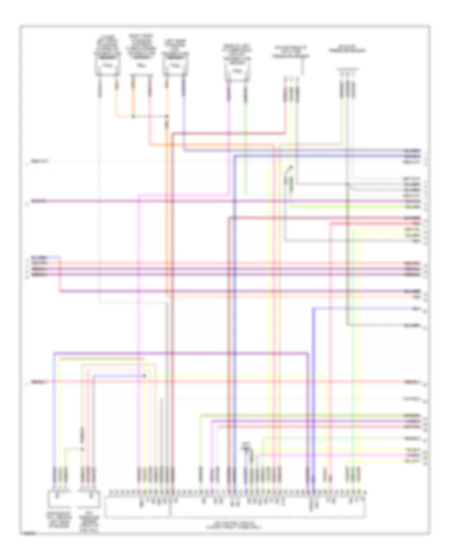
2.1L Turbo Diesel, Engine Performance Wiring Diagram (4 of 10) for Mercedes-Benz E250 Bluetec 4Matic 2014
 https://portal-diagnostov.com/license.html
Automotive Electricians Portal FZCO
Automotive Electricians Portal FZCO
https://portal-diagnostov.com/license.html
https://portal-diagnostov.com/license.html
Automotive Electricians Portal FZCO
Automotive Electricians Portal FZCOList of elements for 2.1L Turbo Diesel, Engine Performance Wiring Diagram (4 of 10) for Mercedes-Benz E250 Bluetec 4Matic 2014:
- (-)
- C19a
- C20a
- C21a
- C22a
- C6i
- Can i h
- Can i l
- E19
- E20
- E21
- E22
- Front sam control unit w/ fuse/ relay module (left rear of engine compt)
- Fuse 10a
- Fuse 15a
- Fuse 20a
- Fuse 40a
- Fuse 5a
- Fuse 7.5a
- Hot at all times
- Hot w/ circuit 15 relay energized
- Lines system computer data
- Pnk
- Pnk/red
- Rear sam control module w/ fuse/relay module (right side of luggage compt)
- Scr
- Sig
2.1L Turbo Diesel, Engine Performance Wiring Diagram (5 of 10) for Mercedes-Benz E250 Bluetec 4Matic 2014
 https://portal-diagnostov.com/license.html
Automotive Electricians Portal FZCO
Automotive Electricians Portal FZCO
https://portal-diagnostov.com/license.html
https://portal-diagnostov.com/license.html
Automotive Electricians Portal FZCO
Automotive Electricians Portal FZCOList of elements for 2.1L Turbo Diesel, Engine Performance Wiring Diagram (5 of 10) for Mercedes-Benz E250 Bluetec 4Matic 2014:
- (not used)
- +5v
- Delivery pump
- Empty
- Fill level sensor
- Full
- Heating element
- Pressure line heating element
- Pressure sensor
- Red
- Reserve
- Sig
- Sp2m
- Switchover valve
- Tank heating element & temperature sensor
- W8/8 (under right rear of luggage compt floor)
2.1L Turbo Diesel, Engine Performance Wiring Diagram (6 of 10) for Mercedes-Benz E250 Bluetec 4Matic 2014
 https://portal-diagnostov.com/license.html
Automotive Electricians Portal FZCO
Automotive Electricians Portal FZCO
https://portal-diagnostov.com/license.html
https://portal-diagnostov.com/license.html
Automotive Electricians Portal FZCO
Automotive Electricians Portal FZCOList of elements for 2.1L Turbo Diesel, Engine Performance Wiring Diagram (6 of 10) for Mercedes-Benz E250 Bluetec 4Matic 2014:
- (+)
- (-)
- (left rear of engine) fuel temperature sensor
- (lower left front of engine) charge air temperature sensor
- (not used)
- (rear of left cylinder bank) coolant temperature sensor
- (right front of engine) upstream turbocharger temperature sensor
- Cdi control module (in right front wheelwell)
- Crankshaft hall sensor (left rear of engine)
- Downstream of air filter pressure sensor
- Drv
- E p3
- Exhaust pressure sensor
- Gnd
- Inj l
- Kwdga
- Lin c1
- Ll tf sig
- Pnk
- Rail pressure sensor (front of fuel rail)
- Sig
- Tmot
- X26-c1
2.1L Turbo Diesel, Engine Performance Wiring Diagram (7 of 10) for Mercedes-Benz E250 Bluetec 4Matic 2014
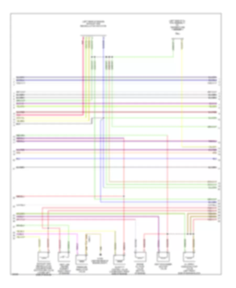 https://portal-diagnostov.com/license.html
Automotive Electricians Portal FZCO
Automotive Electricians Portal FZCO
https://portal-diagnostov.com/license.html
https://portal-diagnostov.com/license.html
Automotive Electricians Portal FZCO
Automotive Electricians Portal FZCOList of elements for 2.1L Turbo Diesel, Engine Performance Wiring Diagram (7 of 10) for Mercedes-Benz E250 Bluetec 4Matic 2014:
- (left rear of engine) exhaust gas recirculation actuator
- (left side of oil pan assembly) oil temperature sensor
- Engine oil pump valve (bottom of engine)
- Exhaust gas recirculation cooler bypass switchover valve (lower left side of engine)
- Heat exchanger shutoff valve
- Oil spray nozzle shutoff valve (left front side of engine block)
- Pnk
- Pressure regulator valve
- Quantity control valve (lower right front side of engine)
- Vent line heater element (right front of engine)
- W16/6 (center rear of engine compt)
- X26-c1
2.1L Turbo Diesel, Engine Performance Wiring Diagram (8 of 10) for Mercedes-Benz E250 Bluetec 4Matic 2014
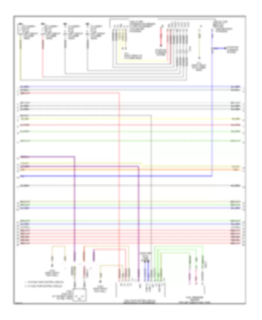 https://portal-diagnostov.com/license.html
Automotive Electricians Portal FZCO
Automotive Electricians Portal FZCO
https://portal-diagnostov.com/license.html
https://portal-diagnostov.com/license.html
Automotive Electricians Portal FZCO
Automotive Electricians Portal FZCOList of elements for 2.1L Turbo Diesel, Engine Performance Wiring Diagram (8 of 10) for Mercedes-Benz E250 Bluetec 4Matic 2014:
- (+)
- (-)
- 1 zyl
- 2 zyl
- 3 zyl
- 4 zyl
- 87f
- Can-c h
- Can-c l
- Computer data lines system
- Cylinder 1 glow plug (left side of cylinder head)
- Cylinder 2 glow plug (left side of cylinder head)
- Cylinder 3 glow plug (left side of cylinder head)
- Cylinder 4 glow plug (left side of cylinder head)
- Ekp
- Fuel filter condensation sensor w/ heating element (top center of engine)
- Fuel pressure sensor (top left side of fuel tank)
- Fuel pump (fp) (in top right side of fuel tank)
- Fuel pump control module (behind right quarterpanel)
- Glow time output stage (center front of engine)
- Htr 1
- Htr 2
- Kds sig
- Lin c1
- Nca
- Pnk
- Red
- Sig
- Starting/ charging system
- W/ fuel pump control module
- W/o fuel pump control module
- W11 (right front of cylinder head)
- W15/1 (right front footwell)
- X214
- X26-c1
- X36/2-c1
2.1L Turbo Diesel, Engine Performance Wiring Diagram (9 of 10) for Mercedes-Benz E250 Bluetec 4Matic 2014
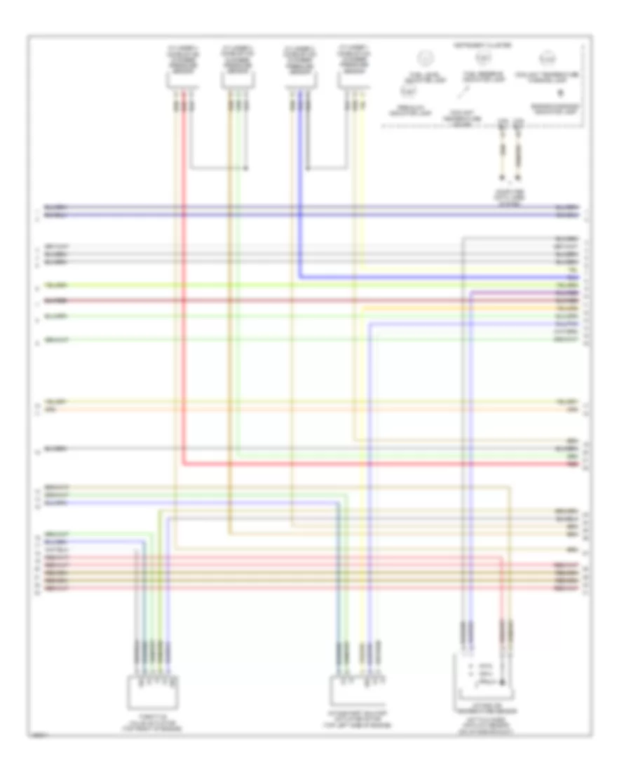 https://portal-diagnostov.com/license.html
Automotive Electricians Portal FZCO
Automotive Electricians Portal FZCO
https://portal-diagnostov.com/license.html
https://portal-diagnostov.com/license.html
Automotive Electricians Portal FZCO
Automotive Electricians Portal FZCOList of elements for 2.1L Turbo Diesel, Engine Performance Wiring Diagram (9 of 10) for Mercedes-Benz E250 Bluetec 4Matic 2014:
- (+)
- (-)
- Can b h
- Can b l
- Computer data lines system
- Coolant temperature gauge
- Coolant temperature warning lamp
- Cylinder 1 combustion chamber pressure sensor
- Cylinder 2 combustion chamber pressure sensor
- Cylinder 3 combustion chamber pressure sensor
- Cylinder 4 combustion chamber pressure sensor
- Engine diagnosis indicator lamp
- Fuel level indicator lamp
- Fuel reserve indicator lamp
- Hot film mass air flow sensor (on intake air duct)
- Instrument cluster
- Intake air temperature sensor
- Intake port shutoff actuator motor (top left side of engine)
- Pre-glow indicator lamp
- Red
- Sig
- Throttle valve actuator (top front of engine)
2.1L Turbo Diesel, Engine Performance Wiring Diagram (10 of 10) for Mercedes-Benz E250 Bluetec 4Matic 2014
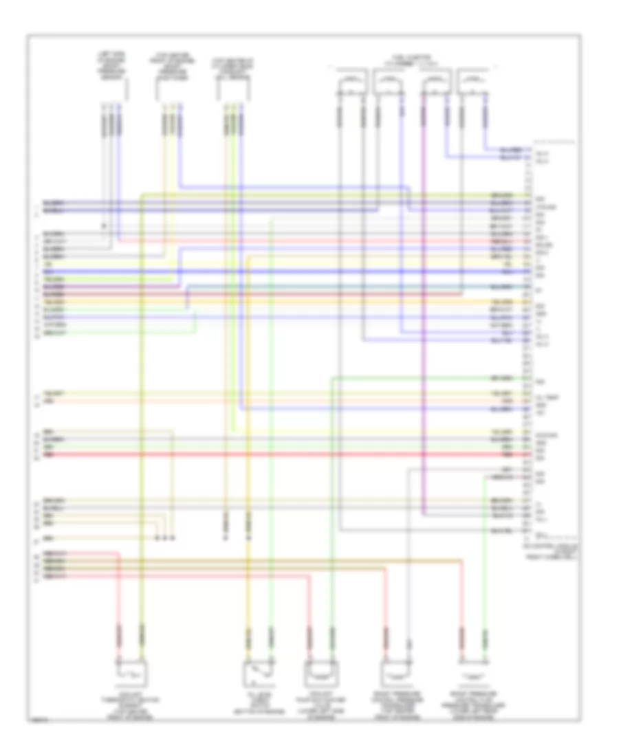 https://portal-diagnostov.com/license.html
Automotive Electricians Portal FZCO
Automotive Electricians Portal FZCO
https://portal-diagnostov.com/license.html
https://portal-diagnostov.com/license.html
Automotive Electricians Portal FZCO
Automotive Electricians Portal FZCOList of elements for 2.1L Turbo Diesel, Engine Performance Wiring Diagram (10 of 10) for Mercedes-Benz E250 Bluetec 4Matic 2014:
- (+)
- (-)
- (left side of engine) boost pressure sensor
- (top center front of engine) boost pressure positioner
- (top center of cylinder head) camshaft hall sensor
- +5v
- Boost pressure control flap pressure transducer (lower left rear side of engine)
- Boost pressure control pressure transducer (top center front of engine)
- Cdi control module (in right front wheelwell)
- Coolant pump switchover valve (lower left side of engine)
- Coolant thermostat heating element (top center front of engine)
- Ealds
- Fuel injector cylinders 1, 2, 3 & 4
- Gnd
- Inj h
- Inj l
- Kts sig
- Nwg sig
- Oil level check switch (bottom of engine)
- Oil temp
- Red
- Sig
- Sig 1
- Sig 2
EXTERIOR LIGHTS
Backup Lamps Wiring Diagram for Mercedes-Benz E250 Bluetec 4Matic 2014
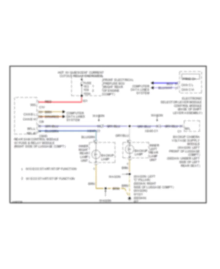 https://portal-diagnostov.com/license.html
Automotive Electricians Portal FZCO
Automotive Electricians Portal FZCO
https://portal-diagnostov.com/license.html
https://portal-diagnostov.com/license.html
Automotive Electricians Portal FZCO
Automotive Electricians Portal FZCOList of elements for Backup Lamps Wiring Diagram for Mercedes-Benz E250 Bluetec 4Matic 2014:
- (wagon: left "c" pillar) (sedan: right side of luggage compt) (wagon) w13/1 (sedan) w7
- 150a
- 30g
- Backup lamp
- C1v
- C6hd
- C9i
- Can b h
- Can b l
- Can c h
- Can c l
- Computer data lines system
- Electronic selector lever module control module (base of shift lever assembly)
- Front electrical prefuse box (right rear of engine compt)
- Fuse
- Hot w/ quiescent current cutout relay energized
- Ig1
- Inner left rear lamp unit
- Inner right rear lamp unit
- Prnd-d+
- Rear sam control module w/ fuse & relay module (right side of luggage compt)
- Red
- Rfl
- Rfl-l
- Rfl-r
- W/ eco start/stop function
- W/o eco start/stop function
- Wagon
- X8/45-c1
- X8/47-c1
Exterior Lamps Wiring Diagram, with Dynamic LED Headlamps (1 of 4) for Mercedes-Benz E250 Bluetec 4Matic 2014
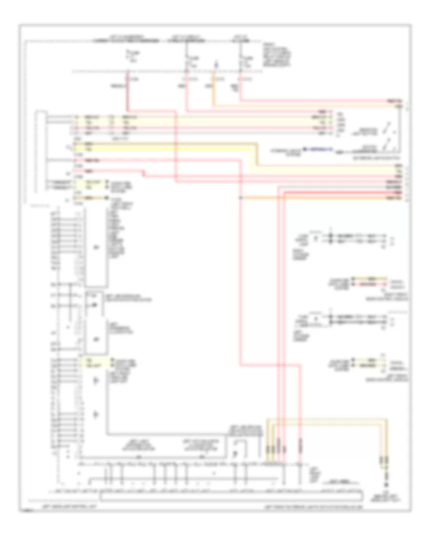 https://portal-diagnostov.com/license.html
Automotive Electricians Portal FZCO
Automotive Electricians Portal FZCO
https://portal-diagnostov.com/license.html
https://portal-diagnostov.com/license.html
Automotive Electricians Portal FZCO
Automotive Electricians Portal FZCOList of elements for Exterior Lamps Wiring Diagram, with Dynamic LED Headlamps (1 of 4) for Mercedes-Benz E250 Bluetec 4Matic 2014:
- (+)
- (not used)
- 15g
- 58d
- C11c
- C13d
- C14m
- C15m
- C16s
- C17c
- C19i
- C22i
- Can b h
- Can b l
- Can e2 h
- Can e2 l
- Computer data lines system
- Exterior lights switch
- Front sam control unit w/ fuse & relay module (left rear of engine compt)
- Fuse 30a
- Fuse 7.5a
- Hot at all times
- Hot w/ circuit 15 relay energized
- Hot w/ quiescent current cutout relay energized
- Interior lights system
- Lds1
- Lds2
- Lds3
- Left active curve illumination actuator motor
- Left cornering illumination
- Left front door control module
- Left front exterior lights actuation module led
- Left front lamp unit
- Left front vario-led lamp unit
- Left headlamp control unit
- Left led driving lights actuation module fan motor
- Left led signaling lights actuation motor
- Left light distribution actuator motor
- Left outside mirror
- Left turn signal light, parking light, side marker light & daytime running light
- Lin 1
- Rear fog light button
- Red
- Right front door control module
- Right outside mirror
- Switch illumination
- Turn signal lamp
- W15/5 (left front footwell)
- W9 (behind left headlight unit)
- X83/11-c1
Exterior Lamps Wiring Diagram, with Dynamic LED Headlamps (2 of 4) for Mercedes-Benz E250 Bluetec 4Matic 2014
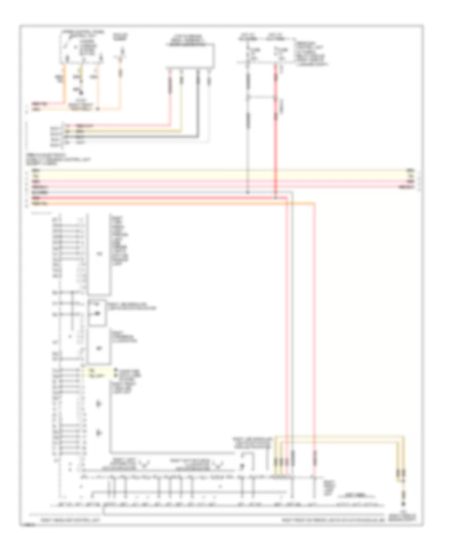 https://portal-diagnostov.com/license.html
Automotive Electricians Portal FZCO
Automotive Electricians Portal FZCO
https://portal-diagnostov.com/license.html
https://portal-diagnostov.com/license.html
Automotive Electricians Portal FZCO
Automotive Electricians Portal FZCOList of elements for Exterior Lamps Wiring Diagram, with Dynamic LED Headlamps (2 of 4) for Mercedes-Benz E250 Bluetec 4Matic 2014:
- (not used)
- (top of brake pedal assembly) stop lamp switch
- 30g
- Analog clock
- Bls h
- Bls l
- Bls m
- Bls v
- C14i
- Computer data lines system
- Fuse 15a
- Fuse 20a
- Hazard warning system button
- Hot at all times
- Lin 1
- Premium electronic stability program control unit (except hybrid)
- Rear sam control unit w/ fuse & relay module (right side of luggage compt)
- Red
- Right active curve illumination actuator motor
- Right cornering illumination
- Right front exterior lights actuation module led
- Right front lamp unit
- Right front vario-led lamp unit
- Right headlamp control unit
- Right led signaling lights actuation module fan motor
- Right led signaling lights actuation motor
- Right light distribution actuator motor
- Right turn signal light, parking light, side marker light & daytime running light
- Upper control panel control unit
- W15/7 (right front footwell)
- W2 (right side of engine compt)
- X25/2-c2
Exterior Lamps Wiring Diagram, with Dynamic LED Headlamps (3 of 4) for Mercedes-Benz E250 Bluetec 4Matic 2014
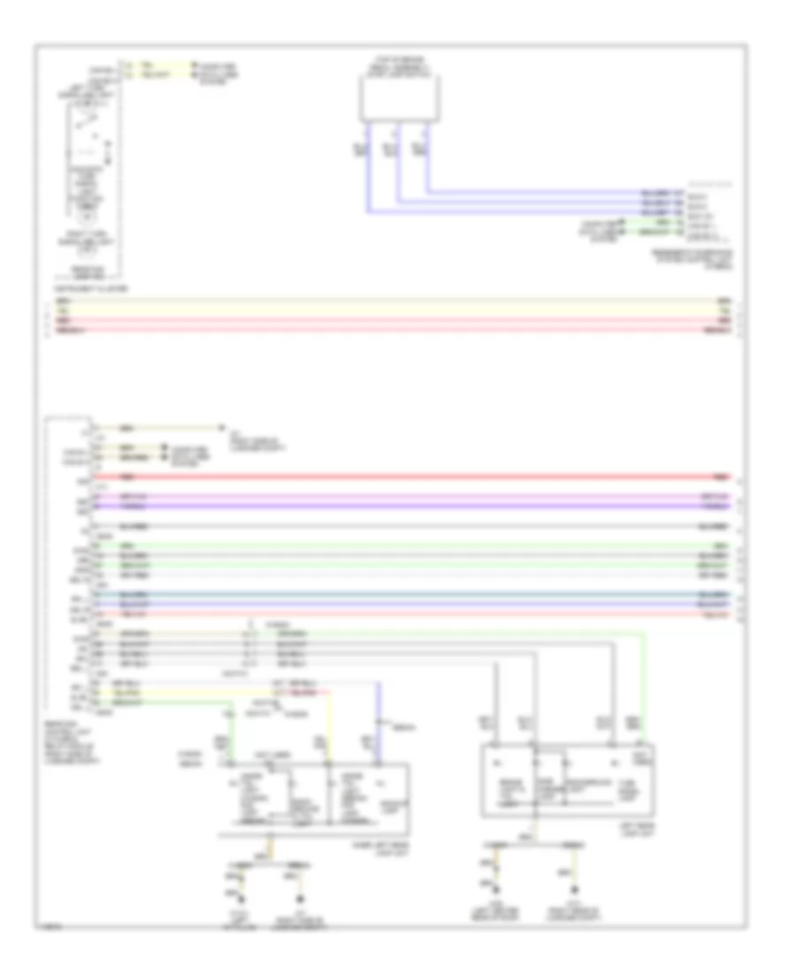 https://portal-diagnostov.com/license.html
Automotive Electricians Portal FZCO
Automotive Electricians Portal FZCO
https://portal-diagnostov.com/license.html
https://portal-diagnostov.com/license.html
Automotive Electricians Portal FZCO
Automotive Electricians Portal FZCOList of elements for Exterior Lamps Wiring Diagram, with Dynamic LED Headlamps (3 of 4) for Mercedes-Benz E250 Bluetec 4Matic 2014:
- (not used)
- (top of brake pedal assembly) stop lamp switch
- 30g
- 49l
- 49r
- 58d
- Acoustic turn signal light function check
- Back- ground & tail light
- Background light
- Backup lamp
- Bls 12v
- Bls h
- Bls m
- Brake light & tail light
- Bsl l
- Bsl r
- C1v
- C5h
- C6hd
- C7i
- Can b h
- Can b l
- Can e1 h
- Can e1 l
- Can e2 h
- Can e2 l
- Computer data lines system
- Diag
- Inner left rear lamp unit
- Inside tail light (sedan) fog lamp (wagon)
- Inside tail light (wagon) fog lamp (sedan)
- Instrument cluster
- Left rear lamp unit
- Left turn signal ind light
- Nsl l
- Nsl r
- Rear fog lamp ind
- Rear sam control unit w/ fuse & relay module (right side of luggage compt)
- Red
- Regenerative braking system control unit (hybrid)
- Rfl l
- Right turn signal ind light
- Sedan
- Side marker lamp
- Sl/bl
- Sml
- Smr
- Turn signal lamp
- W13/1 (left "c" pillar)
- W48 (left center rear of roof)
- W7 (right side of luggage compt)
- W7/1 (right rear of luggage compt)
- Wagon
- X8/47-c1
Exterior Lamps Wiring Diagram, with Dynamic LED Headlamps (4 of 4) for Mercedes-Benz E250 Bluetec 4Matic 2014
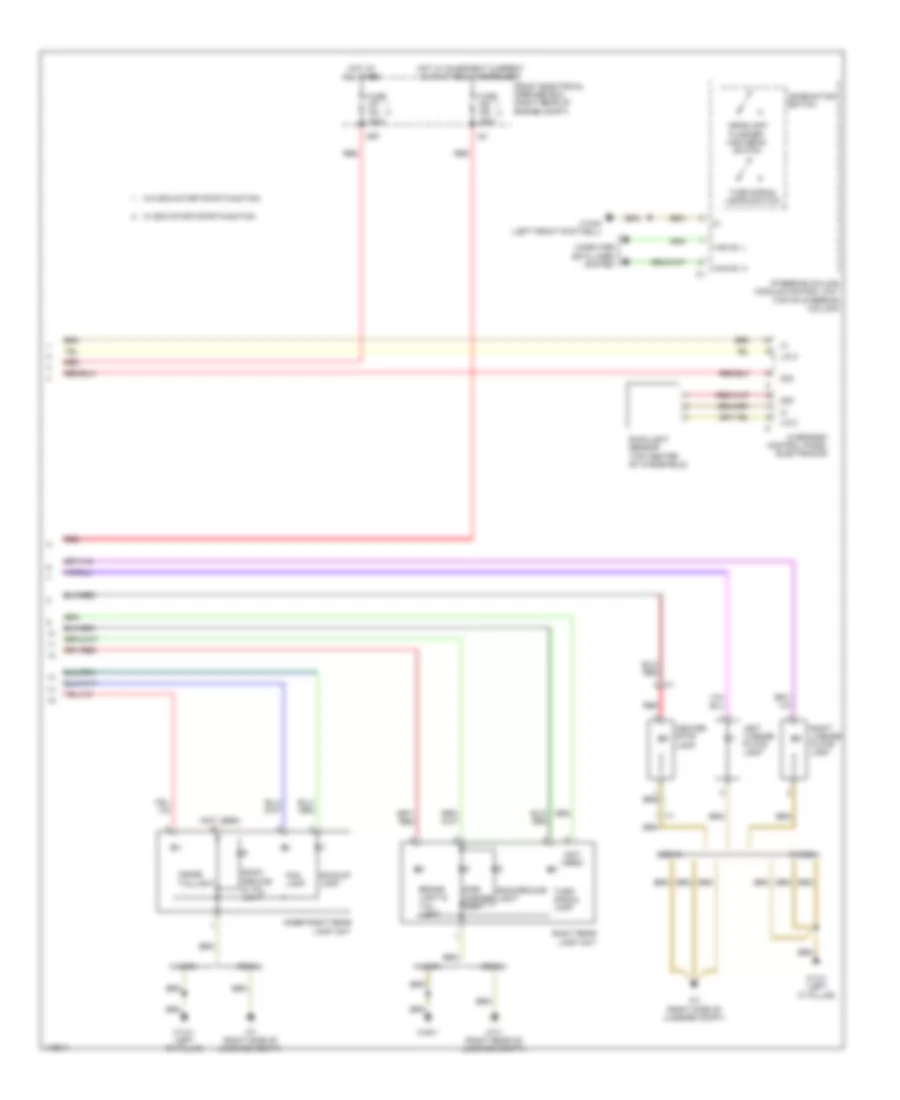 https://portal-diagnostov.com/license.html
Automotive Electricians Portal FZCO
Automotive Electricians Portal FZCO
https://portal-diagnostov.com/license.html
https://portal-diagnostov.com/license.html
Automotive Electricians Portal FZCO
Automotive Electricians Portal FZCOList of elements for Exterior Lamps Wiring Diagram, with Dynamic LED Headlamps (4 of 4) for Mercedes-Benz E250 Bluetec 4Matic 2014:
- (not used)
- 30g
- Back- ground & tail light
- Background light
- Backup lamp
- Brake light & tail light
- Can e1 h
- Can e1 l
- Center stop lamp
- Combination switch
- Computer data lines system
- Flasher/ high beam switch
- Fog lamp
- Front electrical prefuse box (right rear of engine compt)
- Fuse 150a
- Headlamp
- Hot at all times
- Hot w/ quiescent current cutout relay energized
- Ig1
- Inner right rear lamp unit
- Inside taillight
- Left license plate lamp
- Lin 2
- Mr7
- Overhead control panel electronics
- Rain/light sensor (top center of windshield)
- Red
- Right license plate lamp
- Right rear lamp unit
- Sedan
- Side marker lamp
- Steering column module control unit (top of steering column)
- Turn signal lamp
- Turn signal lamps switch
- W/ eco start/stop function
- W/o eco start/stop function
- W13/1 (left "c" pillar)
- W15/5 (left front footwell)
- W48/1
- W7 (right side of luggage compt)
- W7/1 (right rear of luggage compt)
- Wagon
Exterior Lamps Wiring Diagram, without Dynamic LED Headlamps (1 of 3) for Mercedes-Benz E250 Bluetec 4Matic 2014
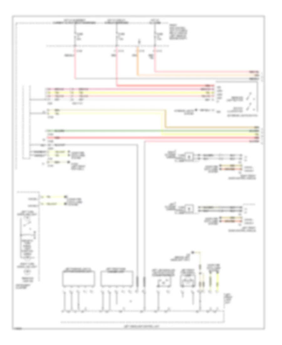 https://portal-diagnostov.com/license.html
Automotive Electricians Portal FZCO
Automotive Electricians Portal FZCO
https://portal-diagnostov.com/license.html
https://portal-diagnostov.com/license.html
Automotive Electricians Portal FZCO
Automotive Electricians Portal FZCOList of elements for Exterior Lamps Wiring Diagram, without Dynamic LED Headlamps (1 of 3) for Mercedes-Benz E250 Bluetec 4Matic 2014:
- (+)
- 15g
- 49l
- 58d
- Acoustic turn signal light function check
- C11c
- C13d
- C14m
- C16s
- C17c
- C18m
- C19i
- C20m
- C22i
- Can b h
- Can b l
- Can e2 h
- Can e2 l
- Computer data lines system
- Exterior lights switch
- Front sam control unit w/ fuse & relay module (left rear of engine compt)
- Fuse 30a
- Fuse 7.5a
- Hot at all times
- Hot w/ circuit 15 relay energized
- Hot w/ quiescent current cutout relay energized
- Instrument cluster
- Interior lights system
- Lds1
- Lds2
- Lds3
- Left front door control module
- Left front lamp unit
- Left front side marker lamp
- Left front turn signal lamp
- Left headlamp control unit
- Left led signaling lights actuation module fan motor
- Left outside mirror
- Left parking light & daytime running light
- Left turn signal ind light
- Lin 1
- Rear fog lamp ind
- Rear fog light button
- Red
- Right front door control module
- Right outside mirror
- Right turn signal ind light
- Switch illumination
- Turn signal lamp
- W15/5 (left front footwell)
- W9 (behind left headlight unit)
- X83/11-c1
Exterior Lamps Wiring Diagram, without Dynamic LED Headlamps (2 of 3) for Mercedes-Benz E250 Bluetec 4Matic 2014
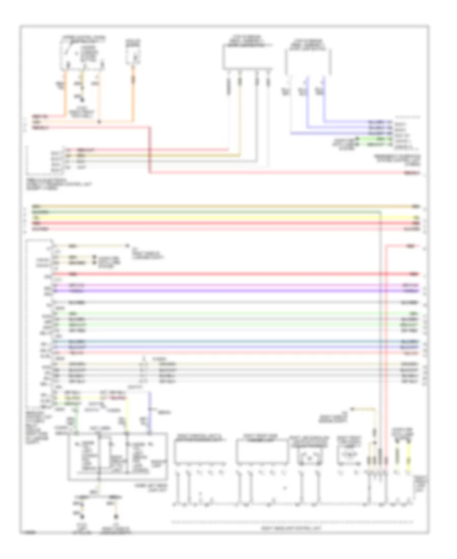 https://portal-diagnostov.com/license.html
Automotive Electricians Portal FZCO
Automotive Electricians Portal FZCO
https://portal-diagnostov.com/license.html
https://portal-diagnostov.com/license.html
Automotive Electricians Portal FZCO
Automotive Electricians Portal FZCOList of elements for Exterior Lamps Wiring Diagram, without Dynamic LED Headlamps (2 of 3) for Mercedes-Benz E250 Bluetec 4Matic 2014:
- (not used)
- (top of brake pedal assembly) stop lamp switch
- 30g
- 49l
- 49r
- 58d
- Analog clock
- Back- ground & tail light
- Backup lamp
- Bls 12v
- Bls h
- Bls l
- Bls m
- Bls v
- Bsl l
- Bsl r
- C1v
- C5h
- C6hd
- C7i
- Can b h
- Can b l
- Can e1 h
- Can e1 l
- Computer data lines system
- Diag
- Hazard warning system button
- Inner left rear lamp unit
- Inside tail light (sedan) fog lamp (wagon)
- Inside tail light (wagon) fog lamp (sedan)
- Lin 1
- Nsl l
- Nsl r
- Premium electronic stability program control unit (except hybrid)
- Rear sam control unit w/ fuse & relay module (right side of luggage compt)
- Red
- Regenerative braking system control unit (hybrid)
- Rfl l
- Right front lamp unit
- Right front side marker lamp
- Right front turn signal lamp
- Right headlamp control unit
- Right led signaling lights actuation module fan motor
- Right parking light & daytime running light
- Sedan
- Sl/bl
- Sml
- Smr
- Upper control panel control unit
- W13/1 (left "c" pillar)
- W15/7 (right front footwell)
- W2 (right side of engine compt)
- W7 (right side of luggage compt)
- Wagon
- X8/47-c1
Exterior Lamps Wiring Diagram, without Dynamic LED Headlamps (3 of 3) for Mercedes-Benz E250 Bluetec 4Matic 2014
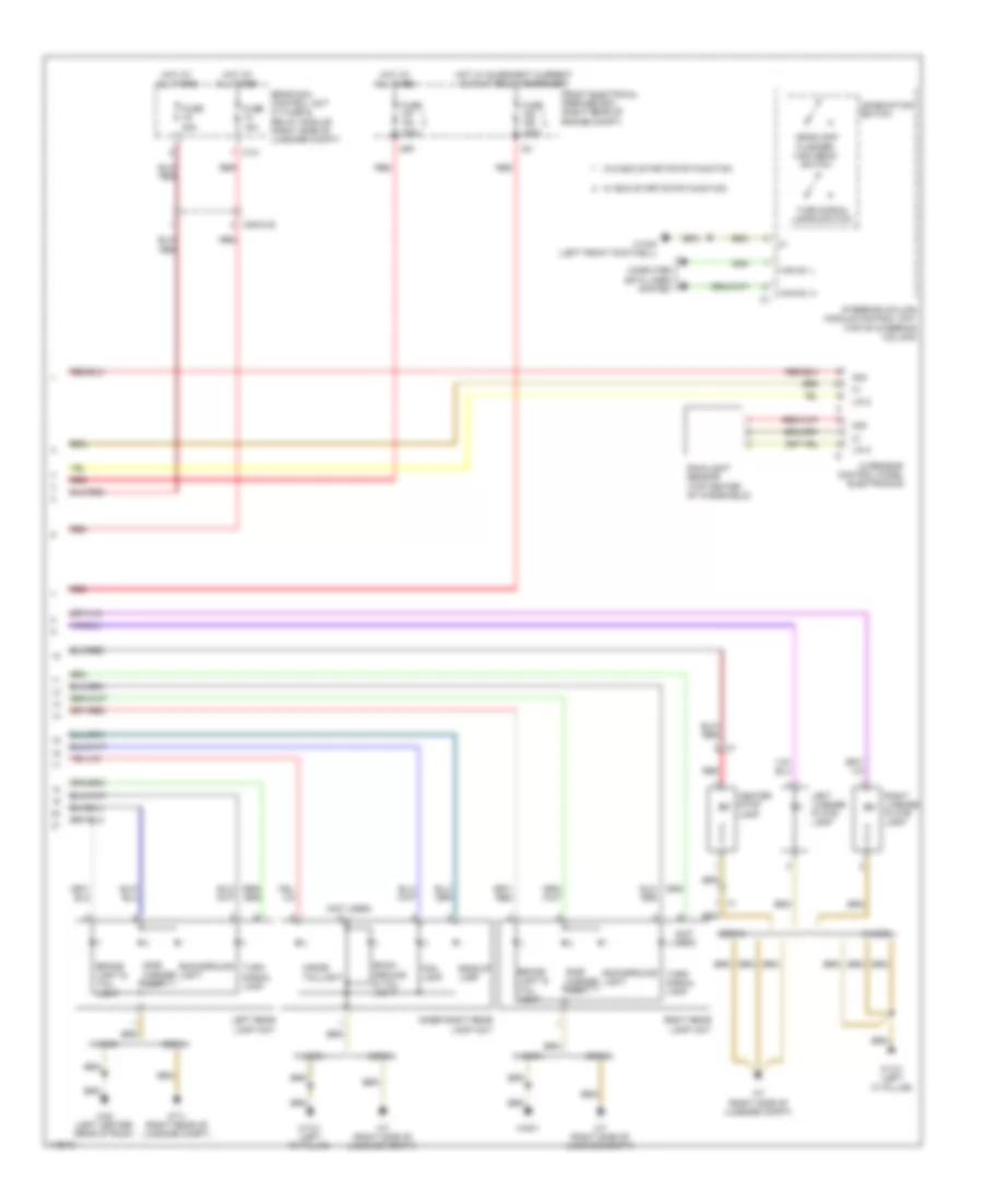 https://portal-diagnostov.com/license.html
Automotive Electricians Portal FZCO
Automotive Electricians Portal FZCO
https://portal-diagnostov.com/license.html
https://portal-diagnostov.com/license.html
Automotive Electricians Portal FZCO
Automotive Electricians Portal FZCOList of elements for Exterior Lamps Wiring Diagram, without Dynamic LED Headlamps (3 of 3) for Mercedes-Benz E250 Bluetec 4Matic 2014:
- (not used)
- 30g
- Back- ground & tail light
- Background light
- Backup lamp
- Brake light & tail light
- C14i
- Can e1 h
- Can e1 l
- Center stop lamp
- Combination switch
- Computer data lines system
- Flasher/ high beam switch
- Fog lamp
- Front electrical prefuse box (right rear of engine compt)
- Fuse 150a
- Fuse 15a
- Fuse 20a
- Headlamp
- Hot at all times
- Hot w/ quiescent current cutout relay energized
- Ig1
- Inner right rear lamp unit
- Inside taillight
- Left license plate lamp
- Left rear lamp unit
- Lin 2
- Mr7
- Overhead control panel electronics
- Rain/light sensor (top center of windshield)
- Rear sam control unit w/ fuse & relay module (right side of luggage compt)
- Red
- Right license plate lamp
- Right rear lamp unit
- Sedan
- Side marker lamp
- Steering column module control unit (top of steering column)
- Turn signal lamp
- Turn signal lamps switch
- W/ eco start/stop function
- W/o eco start/stop function
- W13/1 (left "c" pillar)
- W15/5 (left front footwell)
- W48 (left center rear of roof)
- W48/1
- W7 (right side of luggage compt)
- W7/1 (right rear of luggage compt)
- Wagon
- X25/2-c2
Trailer Light Wiring Diagram for Mercedes-Benz E250 Bluetec 4Matic 2014
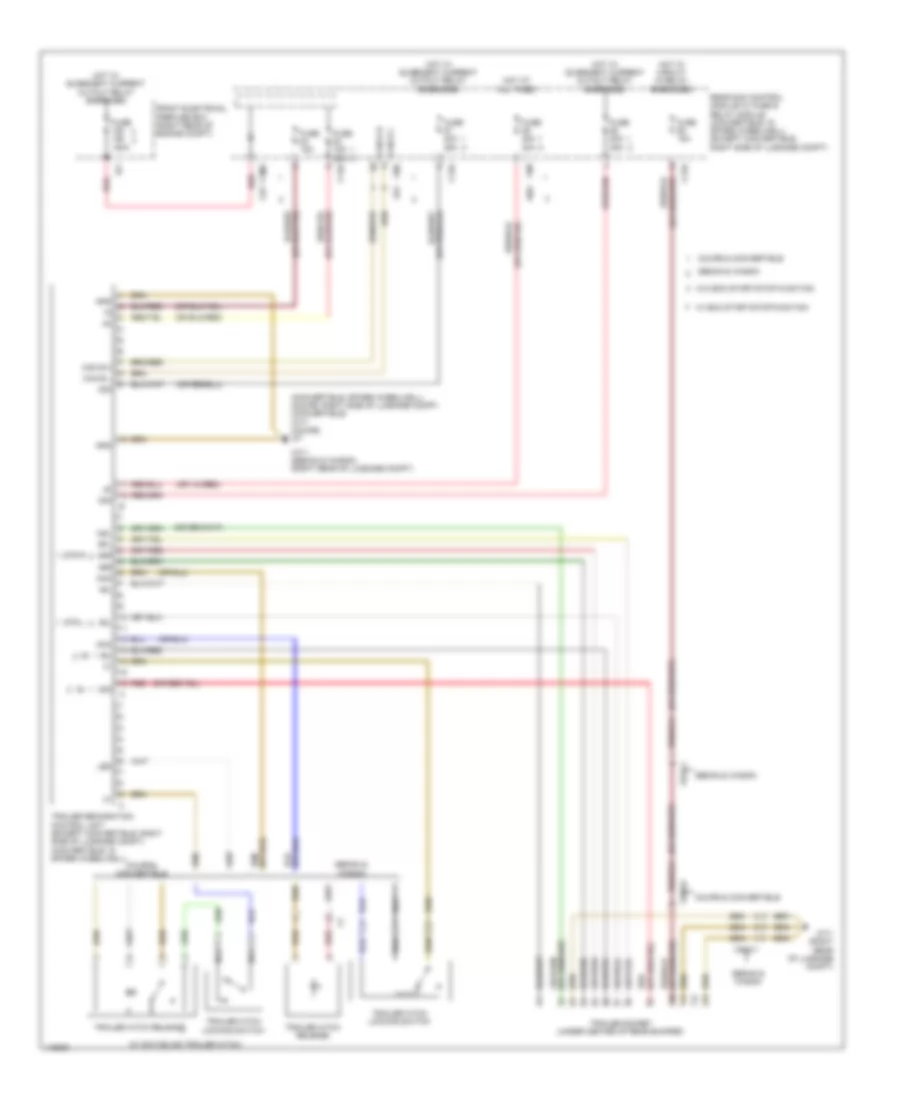 https://portal-diagnostov.com/license.html
Automotive Electricians Portal FZCO
Automotive Electricians Portal FZCO
https://portal-diagnostov.com/license.html
https://portal-diagnostov.com/license.html
Automotive Electricians Portal FZCO
Automotive Electricians Portal FZCOList of elements for Trailer Light Wiring Diagram for Mercedes-Benz E250 Bluetec 4Matic 2014:
- (convertible: spare wheelwell) (coupe: right side of luggage compt) (convertible) w7/7 (coupe) w7
- (w/ swiveling trailer hitch)
- 30g
- 49l
- 49r
- 58l
- 58r
- Aag
- Ahk
- C11
- C13a
- C1v
- C30g
- C5h
- C89
- Can b h
- Can b l
- Coupe & convertible
- Front electrical prefuse box (right rear of engine compt)
- Fuse 150a
- Fuse 15a
- Fuse 15a 30a
- Fuse 20a 25a
- Fuse 20a 30a
- Gnd
- Hot at all times
- Hot w/ circuit 15 relay energized
- Hot w/ quiescent current cutout relay energized
- Ig1
- Led
- Nca
- Nsl
- Rear sam control module w/ fuse & relay module (convertible: in spare wheelwell) (except convertible: right side of luggage compt)
- Red
- Rfl
- Sedan & wagon
- Str l
- Str r
- Trailer hitch locking switch
- Trailer hitch release
- Trailer recognition control unit (except convertible: right side of luggage compt) (convertible: in spare wheelwell)
- Trailer socket (under center of rear bumper)
- W/ eco start/stop function
- W/o eco start/stop function
- W7/1 (right rear of luggage compt)
- W7/1 (sedan & wagon) (right rear of luggage compt)
- X52-c1
- X58/33
GROUND DISTRIBUTION
Ground Distribution Wiring Diagram (1 of 2) for Mercedes-Benz E250 Bluetec 4Matic 2014
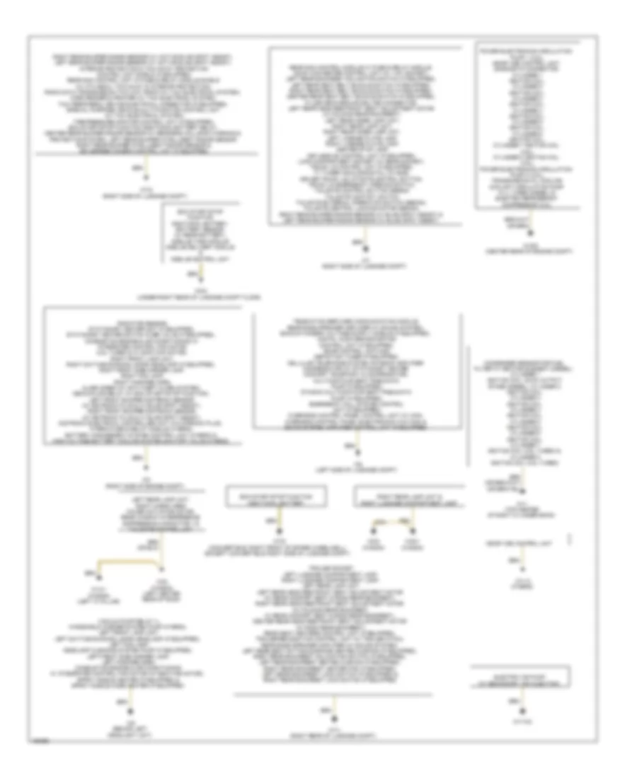 https://portal-diagnostov.com/license.html
Automotive Electricians Portal FZCO
Automotive Electricians Portal FZCO
https://portal-diagnostov.com/license.html
https://portal-diagnostov.com/license.html
Automotive Electricians Portal FZCO
Automotive Electricians Portal FZCOList of elements for Ground Distribution Wiring Diagram (1 of 2) for Mercedes-Benz E250 Bluetec 4Matic 2014:
- (w/ secondary air injection)
- Additional battery
- Condenser sensor for fuel filter w/ heating element (diesel), cylinder 1 ignition coil, glow output stage (diesel), cylinder 2 ignition coil, cylinder 3 ignition coil, cylinder 4 ignition coil, cylinder 5 ignition coil, cylinder 6 ignition coil, cylinder 7 ignition coil (4.6l turbo) & cylinder 8 ignition coil (4.6l turbo)
- Eco start/stop function
- Electric air pump
- Left rear lamp unit, right cargo area cover actuator motor, rear window interference suppression capacitor 1 & tailgate control unit
- Me-sfi (me) control unit
- Power electronics circulation pump 1 (3.5l), me-sfi (me) control unit, diagnostic connector, cylinder 1 ignition coil, cylinder 2 ignition coil, cylinder 3 ignition coil, cylinder 4 ignition coil, cylinder 5 ignition coil, cylinder 6 ignition coil, cylinder 7 ignition coil (4.6l), cylinder 8 ignition coil (4.6l), power electronics circulation pump 2 (3.5l), transmission oil cooling coolant circulation pump (2.1l turbo diesel) & electric refrigerant compressor (3.5l)
- Radiator sensor, stationary heater unit (if equipped), stationary heater switch over valve (if equipped), combustion engine & air conditioning w/ integrated control fan motor (4.6l turbo & w/ 800w fan motor), right front lamp unit, right daytime running lamps headlamp (if equipped), right front side marker lamp, right fog lamp, right fanfare horn, alarm siren (w/ anti-theft alarm system), decoupling relay (w/ eco start/stop function), left front bumper distronic sensor (w/ distronic plus & w/ blind spot assist), right front bumper distronic sensor (w/ distronic plus & w/ blind spot assist), distronic electrical controller unit (w/o stronic plus), hybrid fuse & relay module (hybrid), battery management system control unit (hybrid) & high-voltage battery cooling system shutoff valve (hybrid)
- Rear sam control module w/ fuse & relay module, dc/ac converter control unit (w/ 115v socket), left rear backrest inclination switch (if equipped), left rear seat belt buckle switch (if equipped), right rear seat belt buckle switch (if equipped), center rear seat belt buckle switch (if equipped), filler neck/ground bolted connection, left rear head restraint seat adjustment motor (w/ folding rear backrest), left rear inner lamp unit, right rear lamp unit, right rear inner lamp unit, left license plate lamp, right license plate lamp, center stop lamp, keyless go control unit (if equipped), load compartment socket (w/ rear socket), trunk lid control unit (if equipped), tv tuner (analog/digital) (w/ ece), driver trunk lid/liftgate control button, trunk lid emergency opening switch, tailgate control button (sedan) tailgate contact switch, tailgate external operation switch (sedan), tailgate central locking motor (sedan), right rear bumper radar sensor (w/ blind spot assist) & left rear bumper radar sensor (w/ blind spot assist)
- Right luggage compartment lamp
- Right rear bumper radar sensor (w/ active blind spot assist), left rear bumper radar sensor (w/ active blind spot assist), interior protection & tow-away protection control unit shield (if equipped), rear sam control unit w/ fuse & relay module shield (w/ ata (edw), tow-away & interior protection), radio data transmission two way radio (w/ taxi electrical system), card reader & printer (w/ taxi electrical system), taxi peripheral device electrical connector (if equipped), special purpose vehicle multi-function control unit (w/ taxi electrical system), tire pressure monitor control unit (if equipped), eco start/stop function additional battery relay, center rear bumper radar sensor (w/ rear-end collision warning & protection system), left rear bumper intelligent radar sensor right rear bumper intelligent radar sensor & 360 degree camera control unit (if equipped)
- Right rear lamp unit &
- Trailer socket, left luggage compartment lamp, right luggage compartment lamp, left rear lamp unit, left rear head restraint seat adjustment motor (w/ rear comfort seat & rigid rear backrest), right rear head restraint seat adjustment motor (w/ folding rear backrest, w/ rear comfort seat & rigid rear backrest), center rear head restraint seat adjustment motor (w/ rigid rear backrest), rear seat heaters control unit (if equipped), trailer recognition control unit (w/ trailer hitch), rear bass speaker amplifier (w/ sound system), left rear seat sitting surface heated cushion (if equipped), right rear backrest inclination switch (if equipped), left rear backrest heated cushion (if equipped), right rear backrest heater pad (if equipped), left rear backrest lock switch (if equipped) & right rear backrest lock switch (if equipped)
- Vacuum pump relay (-), windshield washer system pump (hybrid), left front lamp unit, left daytime running lamps headlamp (if equipped), left fog lamp, headlamp cleaning system pump (if equipped), left front side marker lamp, left fanfare horn, combustion engine & air conditioning w/ integrated control fan motor (w/ 650w fan motor), spray nozzle heater (if equipped) & spray nozzle hose heater (if equipped)
- W11 (top center of right cylinder bank)
- W11/3 (hybrid)
- W11w2
- W13/1 (wagon) (left "c" pillar)
- W16/5 (center rear of engine compt)
- W2 (right side of engine compt)
- W48 (wagon) (left center rear of roof)
- W48/1 (wagon)
- W6 (left side of luggage compt)
- W7 (right side of luggage compt)
- W7/1 (right rear of luggage compt)
- W7/6 (convertible: right front of spare wheelwell) (except convertible: right side of luggage compt)
- W7/8 (right side of luggage compt)
- W8/2 (wagon)
- W8/8 (under right rear of luggage compt floor)
- W9 (behind left headlight unit)
Ground Distribution Wiring Diagram (2 of 2) for Mercedes-Benz E250 Bluetec 4Matic 2014
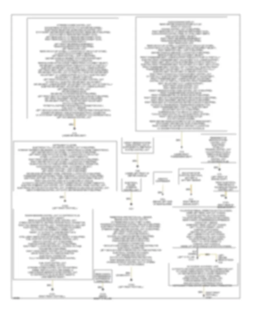 https://portal-diagnostov.com/license.html
Automotive Electricians Portal FZCO
Automotive Electricians Portal FZCO
https://portal-diagnostov.com/license.html
https://portal-diagnostov.com/license.html
Automotive Electricians Portal FZCO
Automotive Electricians Portal FZCOList of elements for Ground Distribution Wiring Diagram (2 of 2) for Mercedes-Benz E250 Bluetec 4Matic 2014:
- (left "c" pillar) w13/1
- (left center rear of roof) w48
- (right front footwell) w15/7
- Ac housing, glove box lamp, automatic air conditioning control & operating unit (w/ 3-zone thermotronic), ptc heater booster (w/ heater booster & w/ 2-zone thermatic), glove box socket (if equipped), upper control panel control unit, parking brake indicator switch, analog clock (late production) & instrument panel switch group (early production)
- Airmatic compressor
- Audio/command display, rear center console power outlet, radio (w/ audio 20), comand control unit (if equipped), right rear display (w/ rear entertainment (dvd)), audio/comand control panel (w/ intelligent servo module for direct select), right front reversible emergency tensioning retractor (if equipped), right rear door lock, rear air outlet symbol illumination (w/ air outlet symbol illumination & w/ intelligent servo module for direct select), right rear footwell lamp (if equipped), center console ambiance illumination (if equipped), rear blower motor (w/o direct select), front passenger seat lumbar support pneumatic pump (w/ partially electric front passenger seat adjustment & w/ lumbar support), right front seat ventilation blower regulator (w/ partially electric front passenger seat adjustment & w/ seat ventilation), front passenger seat control unit (w/ partially electric front passenger seat adjustment, w/ lumbar support & w/ fully electric seat adjustment w/ memory function), right front dynamic multicontour seat control unit (w/ partially electric front passenger seat adjustment), front passenger seat lumbar support adjustment control unit (w/ partially electric front passenger seat adjustment & w/ lumbar support), right front door control unit, right rear door control unit, weight sensing system (wss) control unit (if equipped), front passenger side air bag squib, front passenger pelvis air bag squib (if equipped), right front seat sitting surface heated cushion (if equipped), right front backrest heated cushion (if equipped), right rear seat sitting surface heated cushion (if equipped), automatic transmission transmission mode button, front passenger seat partially electric seat adjustment switch (if equipped), suspension button group (w/ airmatic), two-way radio switch (w/ taxi electrical system), front vehicle interior power outlet (w/o active sub woofer), rear center console power outlet (w/ rear socket), stationary heater fuel pump (if equipped), front cigarette lighter w/ ashtray illumination (w/ smoker package) & navigation module
- Eco start/stop function additional battery & battery sensor
- Electrical power steering control unit
- Front electrical prefuse box & power electronics control unit
- Instrument cluster, electronic toll collection control unit (if equipped), interior temperature sensor, (w/ 2 zone thermotronic & 3-zone thermotronic), left center air outlet symbol illumination (if equipped), left front side air outlet symbol illumination (w/ air outlet symbol illumination) (w/ 2-zone thermatic), right front side air outlet symbol illumination (if equipped), right center air outlet symbol illumination (if equipped), telematics can voltage distributor electrical connector, audio/comand control panel (w/o direct select), right front footwell lamp (if equipped), left front footwell lamp (if equipped), driver side instrument panel ambiance illumination (if equipped), passenger side instrument panel ambiance illumination (if equipped), additional battery (w/ intelligent servo module for direct select), front sam control module w/ fuse & relay module, automatic air conditioning control & operating unit (2-zone thermatic), electric steering lock control unit, upper control panel control unit, electronic ignition switch control unit, steering column module control unit, media interface control unit & ptc heater booster (if equipped)
- Nitrogen oxides control unit downstream of scr catalytic converter (diesel), electronic selector lever module control unit, stationary heater radio remote control receiver (if equipped), dvd player (w/ rear entertainment (dvd)), left rear display (w/ rear entertainment (dvd)), right rear display (w/ rear entertainment (dvd)), audio/comand display, left front reversible emergency tensioning retractor (if equipped), left rear door lock, rear air outlet symbol illumination (w/ air outlet symbol illumination & w/o direct select), left rear footwell lamp (if equipped), center console armrest stowage compartment switch & controls illumination rear blower motor (3-zone thermotronic w/o direct select), driver seat lumbar support pneumatic pump (w/ partially electric driver seat adjustment & w/ lumbar support), left front seat ventilation blower regulator (if equipped), driver seat control unit (w/ partially electric driver seat adjustment, w/ lumbar support & w/ fully electric seat adjustment w/ memory function), left front dynamic multicontour seat control unit (w/ partially electric driver seat adjustment), driver seat lumbar support adjustment control unit (w/ partially electric driver seat adjustment & w/ lumbar support), left rear door control unit, driver sidebag squib, driver pelvis air bag squib (if equipped), left front seat sitting surface heated cushion (if equipped), left front backrest heated cushion (if equipped), driver seat partially electric seat adjustment switch (if equipped), potential distributor electrical connector (can i), fuel quality sensor, left vehicle floor interior can voltage distributor electrical connector (sedan), mobile phone electrical connector (w/ stationary heater & comfort telephony w/o compensator) & left nox sensor control unit
- Pedestrian protection hall sensor, engine hood contact switch (w/ pedestrian & anti-theft alarm), panoramic sliding roof control module (if equipped), electronic transmission control unit (if equipped), steering wheel heater control unit (if equipped), left front door control unit, left front illuminated door sill molding voltage converter (if equipped), wiper park heater (if equipped), parking brake indicator switch, diagnostic connector, vehicle floor chassis can voltage distributor electrical connector, left vehicle floor interior can voltage distributor electrical connector (wagon), left engine hood contact switch (w/o pedestrian protection), right engine hood contact switch & chassis gateway control unit (w/ stereo multifunction camera)
- Radar sensors control unit (w/ distronic plus & blind spot assist), rear axle electronic level control unit, hybrid can potential distributor electrical connector, right nox sensor control unit, transmission oil auxiliary pump control unit, stereo multi-function camera, multi-function camera (w/ speed limit assist, w/ automatic lane recognition & w/ interior light package), intelligent servo module for direct select (if equipped), fuel pump (fp) (w/o fuel system control unit), airmatic control unit (if equipped), parking system control unit (if equipped), right front illuminated door sill molding voltage converter (if equipped), night vision assist control unit (if equipped), drive train can voltage distributor electrical connector, fully integrated transmission control unit, fuel pump control unit, clutch pedal switch, nitrogen oxides control unit downstream diesel particulate filter (diesel) & video & radar sensor system control unit (w/ distronic plus, blind spot assist & lane keeping assist)
- Rear window interference suppression capacitor 2
- Regenerative braking system control unit, electronic stability program control unit (w/o distronic plus) & premium electronic stability program control unit (w/ distronic plus)
- Tailgate external operation switch (wagon), inner left rear lamp unit (wagon), tailgate control button (wagon), tailgate central locking motor (wagon), rear window interference suppression capacitor 1 (sedan), inner right rear lamp unit (wagon) left tailgate ambient lamp & warning lamp (wagon), central stop lamp (wagon), left license plate lamp (wagon), right license plate lamp (wagon), tailgate wiper motor (wagon), right tail gate ambient & warning lamp (wagon) & inside lift gate handle flap switch (wagon)
- W10 (right rear of engine compt)
- W13/2 (sedan) (right "c" pillar)
- W15/1 (right front footwell)
- W15/2 (left front footwell)
- W15/5 (left front footwell)
- W16/4 (right rear of engine compt)
- W18 (under driver's seat)
- W19 (under front passenger's seat)
- W2/1
- W26 (under left front of center console)
- W6/4 (behind left side of rear bumper)
- W70 (left front of engine compt)
HEADLIGHTS
Headlights Wiring Diagram, with Dynamic LED Headlamps (1 of 3) for Mercedes-Benz E250 Bluetec 4Matic 2014
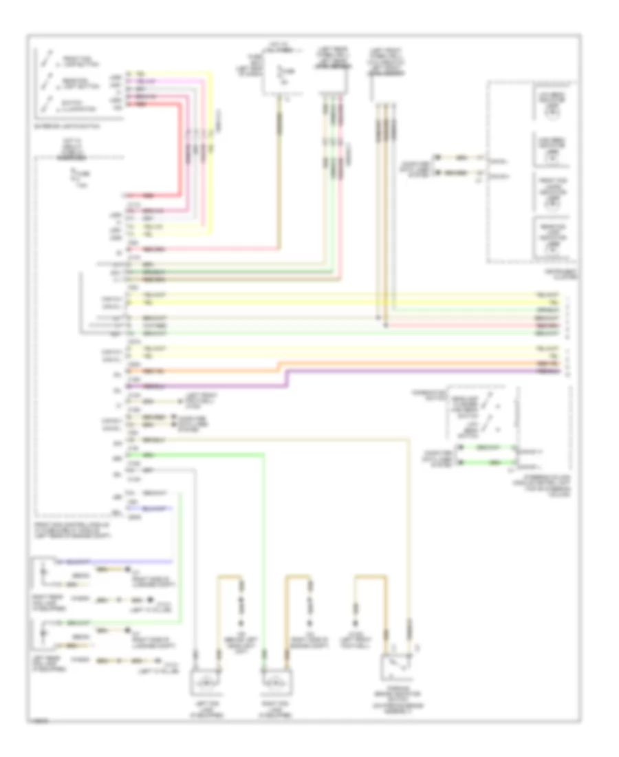 https://portal-diagnostov.com/license.html
Automotive Electricians Portal FZCO
Automotive Electricians Portal FZCO
https://portal-diagnostov.com/license.html
https://portal-diagnostov.com/license.html
Automotive Electricians Portal FZCO
Automotive Electricians Portal FZCOList of elements for Headlights Wiring Diagram, with Dynamic LED Headlamps (1 of 3) for Mercedes-Benz E250 Bluetec 4Matic 2014:
- (+)
- (left front footwell) w15/5
- (left front wheelwell) (w/o airmatic) left front level sensor
- (left rear wheelwell) left rear level sensor
- 15g
- 30l
- 49r
- 55l
- 55r
- C11c
- C14m
- C15m
- C17c
- C19i
- C20m
- C21m
- C22i
- C5h
- C6hd
- Can b h
- Can b l
- Can e1 h
- Can e1 l
- Can g h
- Can g l
- Combination switch
- Computer data lines system
- Exterior lights switch
- Front fog lamp button
- Front fog lamps indicator lamp
- Front sam control module w/ fuse & relay module (left rear of engine compt)
- Fuse 5a
- Fuse 7.5a
- Fuse box (left end of dash)
- Headlamp flasher/ high beam switch
- High beam indicator lamp
- Hot at all times
- Hot w/ circuit 15 relay energized
- Instrument cluster
- Lds1
- Lds2
- Lds3
- Left fog lamp (if equipped)
- Left rear fog lamp (if equipped)
- Low beam indicator lamp
- Low beam switch
- Parking brake indicator switch (on parking brake assembly)
- Rear fog lamp indicator lamp
- Rear fog light button
- Red
- Right fog lamp (if equipped)
- Right rear fog lamp (if equipped)
- Sedan
- Sig
- Sml
- Steering column module control unit (top of steering column)
- Switch illumination
- W13/1 (left "c" pillar)
- W15/2 (left front footwell)
- W2 (right side of engine compt)
- W7 (right side of luggage compt)
- W9 (behind left headlight unit)
- Wagon
- X62/32-c1
- X83/11-c1
Headlights Wiring Diagram, with Dynamic LED Headlamps (2 of 3) for Mercedes-Benz E250 Bluetec 4Matic 2014
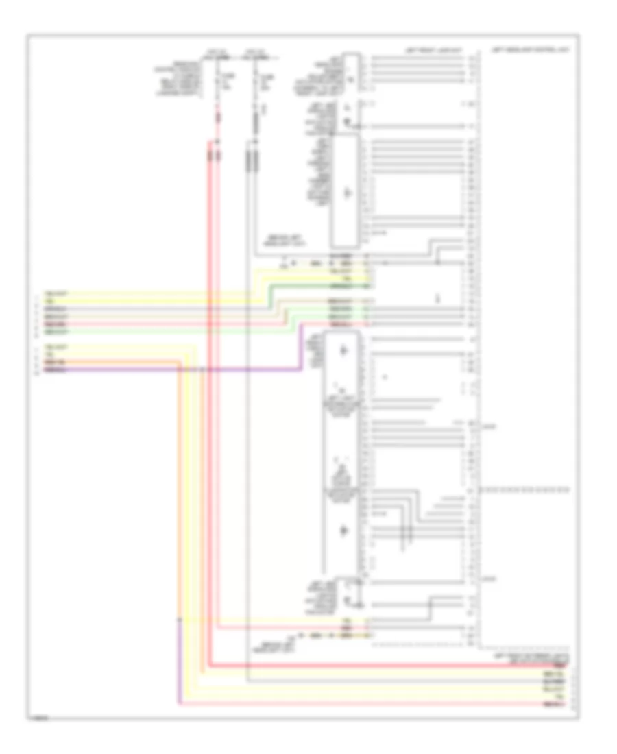 https://portal-diagnostov.com/license.html
Automotive Electricians Portal FZCO
Automotive Electricians Portal FZCO
https://portal-diagnostov.com/license.html
https://portal-diagnostov.com/license.html
Automotive Electricians Portal FZCO
Automotive Electricians Portal FZCOList of elements for Headlights Wiring Diagram, with Dynamic LED Headlamps (2 of 3) for Mercedes-Benz E250 Bluetec 4Matic 2014:
- (behind left headlight unit)
- C14i
- Fuse 15a
- Fuse 20a
- Hot at all times
- Left active curve illumination actuator motor
- Left front exterior lights led actuation module
- Left front lamp unit
- Left front vario- led lamp unit
- Left headlamp control unit
- Left headlamp range adjustment actuator motor (integral to left front lamp unit)
- Left led signaling lights actuation module fan motor
- Left light distribution actuator motor
- Left turn signal light/ parking light/ side marker light & daytime running light
- Lin g1
- Rear sam control module w/ fuse & relay module (right side of luggage compt)
- Red
- W9 (behind left headlight unit)
Headlights Wiring Diagram, with Dynamic LED Headlamps (3 of 3) for Mercedes-Benz E250 Bluetec 4Matic 2014
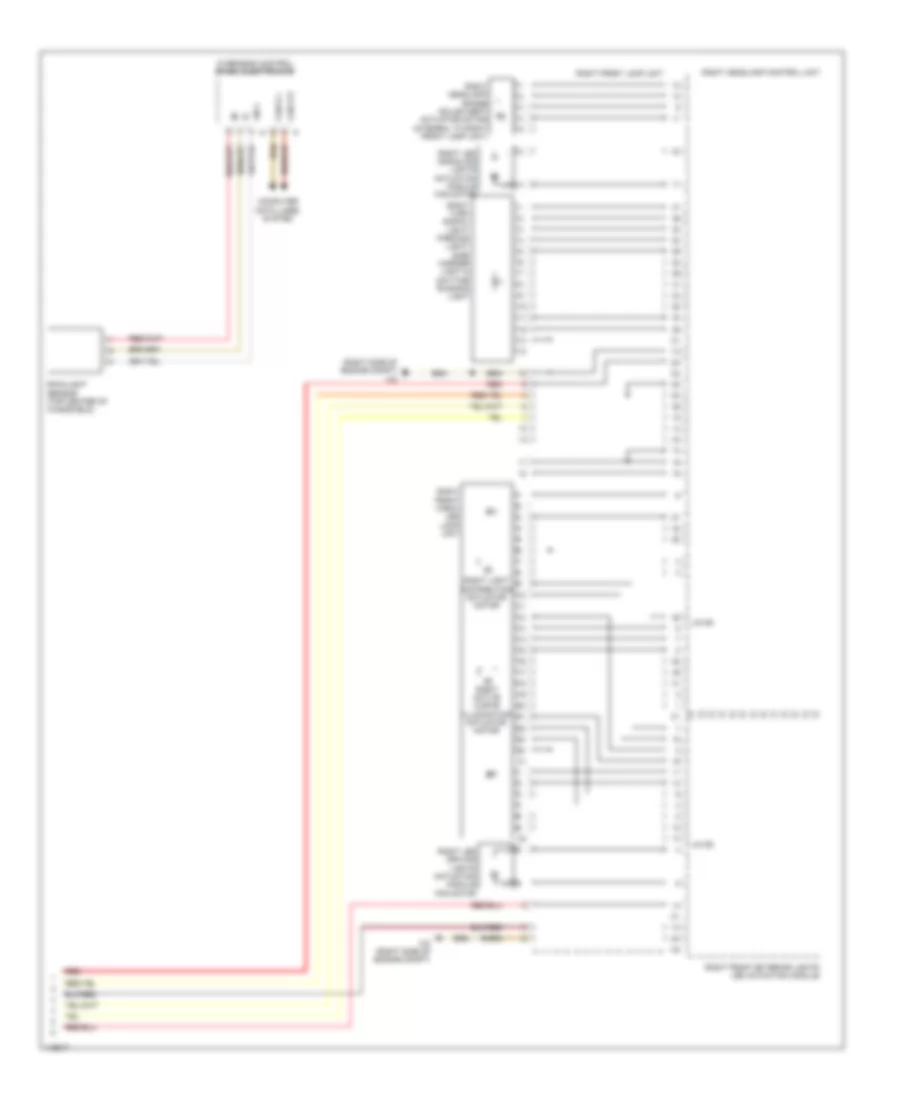 https://portal-diagnostov.com/license.html
Automotive Electricians Portal FZCO
Automotive Electricians Portal FZCO
https://portal-diagnostov.com/license.html
https://portal-diagnostov.com/license.html
Automotive Electricians Portal FZCO
Automotive Electricians Portal FZCOList of elements for Headlights Wiring Diagram, with Dynamic LED Headlamps (3 of 3) for Mercedes-Benz E250 Bluetec 4Matic 2014:
- (right side of engine compt) w2
- Can b h
- Can b l
- Computer data lines system
- Lin 2
- Lin g2
- Overhead control panel electronics
- Rain/light sensor (top center of windshield)
- Red
- Right active curve illumination actuator motor
- Right front exterior lights led actuation module
- Right front lamp unit
- Right front vario- led lamp unit
- Right headlamp control unit
- Right headlamp range adjustment actuator motor (integral to right front lamp unit)
- Right led driving lights actuation module fan motor
- Right led signaling lights actuation module fan motor
- Right light distribution actuator motor
- Right turn signal light/ parking light/ side marker light & daytime running light
- W2 (right side of engine compt)
Headlights Wiring Diagram, without Dynamic LED Headlamps (1 of 2) for Mercedes-Benz E250 Bluetec 4Matic 2014
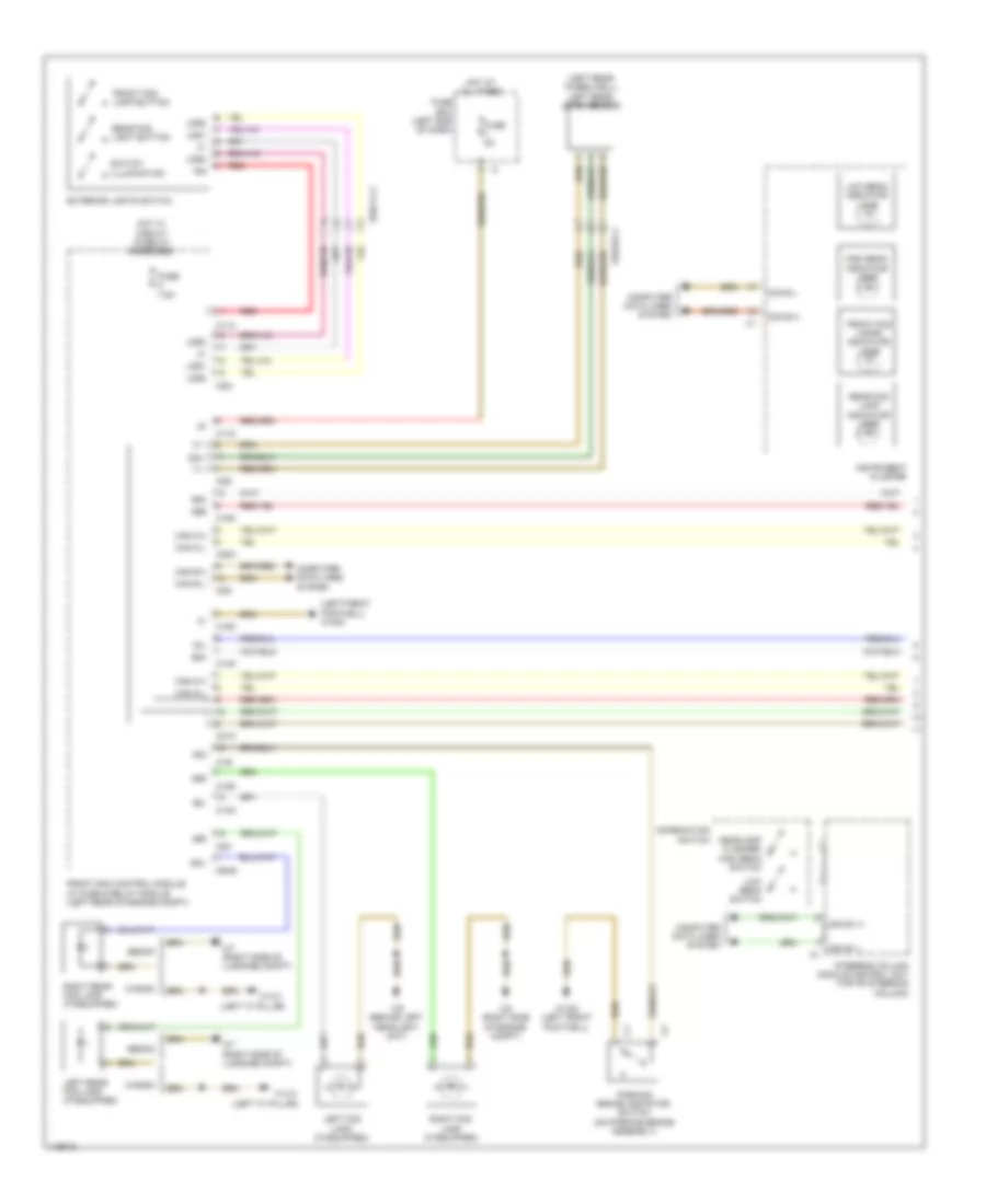 https://portal-diagnostov.com/license.html
Automotive Electricians Portal FZCO
Automotive Electricians Portal FZCO
https://portal-diagnostov.com/license.html
https://portal-diagnostov.com/license.html
Automotive Electricians Portal FZCO
Automotive Electricians Portal FZCOList of elements for Headlights Wiring Diagram, without Dynamic LED Headlamps (1 of 2) for Mercedes-Benz E250 Bluetec 4Matic 2014:
- (+)
- (left "c" pillar)
- (left front footwell) w15/5
- (left rear wheelwell) left rear level sensor
- 15g
- 30l
- 49r
- 55l
- 55r
- 56a
- 56b
- C11c
- C14m
- C15m
- C17c
- C19i
- C20m
- C21m
- C22i
- C5h
- C6hd
- Can b h
- Can b l
- Can e1 h
- Can e1 l
- Can g h
- Can g l
- Combination switch
- Computer data lines system
- Exterior lights switch
- Front fog lamp button
- Front fog lamps indicator lamp
- Front sam control module w/ fuse & relay module (left rear of engine compt)
- Fuse 5a
- Fuse 7.5a
- Fuse box (left end of dash)
- Headlamp flasher/ high beam switch
- High beam indicator lamp
- Hot at all times
- Hot w/ circuit 15 relay energized
- Instrument cluster
- Lds1
- Lds2
- Lds3
- Left fog lamp (if equipped)
- Left rear fog lamp (if equipped)
- Low beam indicator lamp
- Low beam switch
- Parking brake indicator switch (on parking brake assembly)
- Rear fog lamp indicator lamp
- Rear fog light button
- Red
- Right fog lamp (if equipped)
- Right rear fog lamp (if equipped)
- Sedan
- Sig
- Sml
- Steering column module control unit (top of steering column)
- Switch illumination
- W13/1
- W13/1 (left "c" pillar)
- W15/2 (left front footwell)
- W2 (right side of engine compt)
- W7 (right side of luggage compt)
- W9 (behind left headlight unit)
- Wagon
- X62/32-c1
- X83/11-c1
Headlights Wiring Diagram, without Dynamic LED Headlamps (2 of 2) for Mercedes-Benz E250 Bluetec 4Matic 2014
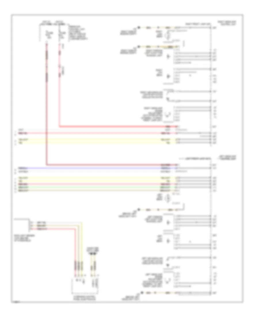 https://portal-diagnostov.com/license.html
Automotive Electricians Portal FZCO
Automotive Electricians Portal FZCO
https://portal-diagnostov.com/license.html
https://portal-diagnostov.com/license.html
Automotive Electricians Portal FZCO
Automotive Electricians Portal FZCOList of elements for Headlights Wiring Diagram, without Dynamic LED Headlamps (2 of 2) for Mercedes-Benz E250 Bluetec 4Matic 2014:
- C14i
- Can b h
- Can b l
- Computer data lines system
- Fuse 15a
- Fuse 20a
- Hot at all times
- Left front lamp unit
- Left headlamp control unit
- Left headlamp range adjustment actuator motor (integral to left front lamp unit)
- Left high beam
- Left led signaling lights actuation module fan motor
- Left low beam
- Left parking light & daytime running light
- Lin 2
- Overhead control panel electronics
- Rain/light sensor (top center of windshield)
- Rear sam control unit w/ fuse & relay module (right side of luggage compt)
- Red
- Right front lamp unit
- Right headlamp control unit
- Right headlamp range adjustment actuator motor (integral to right front lamp unit)
- Right high beam
- Right led signaling lights actuation module fan motor
- Right low beam
- Right parking light & daytime running light
- W2 (right side of engine compt)
- W9 (behind left headlight unit)
- X25/2-c2
HORN
Horn Wiring Diagram for Mercedes-Benz E250 Bluetec 4Matic 2014
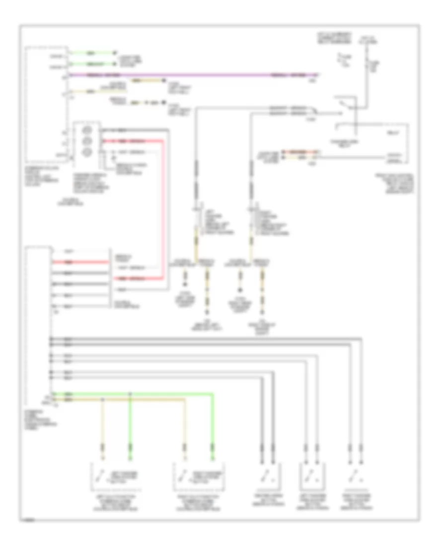 https://portal-diagnostov.com/license.html
Automotive Electricians Portal FZCO
Automotive Electricians Portal FZCO
https://portal-diagnostov.com/license.html
https://portal-diagnostov.com/license.html
Automotive Electricians Portal FZCO
Automotive Electricians Portal FZCOList of elements for Horn Wiring Diagram for Mercedes-Benz E250 Bluetec 4Matic 2014:
- (or red)
- C15m
- C22i
- C5c
- Can b h
- Can b l
- Can e1 h
- Can e1 l
- Center horns button (sedan & wagon)
- Computer data lines system
- Coupe & convertible
- Data
- Fanfare horn relay
- Fanfare horns & air bag clock spring contact (part of steering column module)
- Front sam control module w/ fuse/ relay module (left rear of engine compt)
- Fuse 31b 15a
- Fuse 7.5a
- Gnd
- Hot at all times
- Hot w/ quiescent current cutout relay energized
- Left fanfare horn (behind left corner of front bumper)
- Left fanfare horn system button
- Left fanfare horn system button (sedan & wagon)
- Left multi-function steering wheel button group (coupe & convertible)
- Red
- Relay
- Right fanfare horn (behind right corner of front bumper)
- Right fanfare horn system button
- Right fanfare horn system button (sedan & wagon)
- Right multi-function steering wheel button group (coupe & convertible)
- Sedan & wagon
- Sedan & wagon coupe & convertible
- Steering column module control unit (top of steering column)
- Steering wheel electronics (inside steering wheel)
- W15/5 (left front footwell)
- W16/3 (left side of engine compt)
- W16/4 (right rear of engine compt)
- W2 (right side of engine compt)
- W9 (behind left headlight unit)
INSTRUMENT CLUSTER
Collision Avoidance Wiring Diagram for Mercedes-Benz E250 Bluetec 4Matic 2014
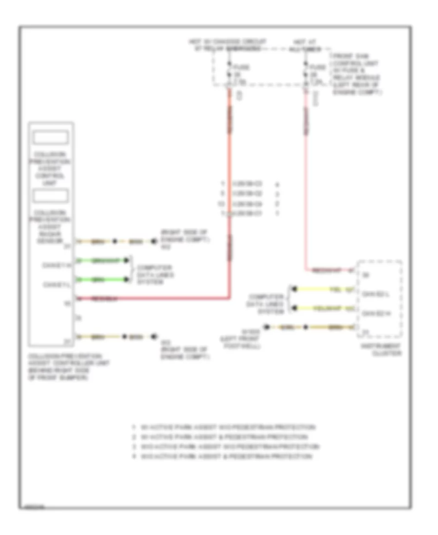 https://portal-diagnostov.com/license.html
Automotive Electricians Portal FZCO
Automotive Electricians Portal FZCO
https://portal-diagnostov.com/license.html
https://portal-diagnostov.com/license.html
Automotive Electricians Portal FZCO
Automotive Electricians Portal FZCOList of elements for Collision Avoidance Wiring Diagram for Mercedes-Benz E250 Bluetec 4Matic 2014:
- (right side of engine compt) w2
- C11c
- C2i
- Can e1 h
- Can e1 l
- Can e2 h
- Can e2 l
- Collision prevention assist control unit
- Collision prevention assist controller unit (behind right side of front bumper)
- Collision prevention assist radar sensor
- Computer data lines system
- Front sam control unit w/ fuse & relay module (left rear of engine compt)
- Fuse 7.5a
- Hot at all times
- Hot w/ chassis circuit 87 relay energized
- Instrument cluster
- W/ active park assist & pedestrian protection
- W/ active park assist w/o pedestrian protection
- W/o active park assist & pedestrian protection
- W/o active park assist w/o pedestrian protection
- W15/5 (left front footwell)
- W2 (right side of engine compt)
- X26/38-c1
- X26/38-c2
- X26/38-c3
- X26/38-c4
Instrument Cluster Wiring Diagram (1 of 2) for Mercedes-Benz E250 Bluetec 4Matic 2014
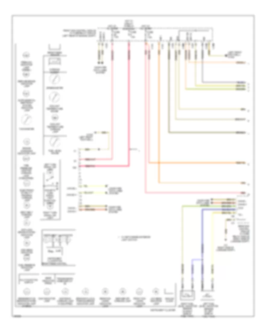 https://portal-diagnostov.com/license.html
Automotive Electricians Portal FZCO
Automotive Electricians Portal FZCO
https://portal-diagnostov.com/license.html
https://portal-diagnostov.com/license.html
Automotive Electricians Portal FZCO
Automotive Electricians Portal FZCOList of elements for Instrument Cluster Wiring Diagram (1 of 2) for Mercedes-Benz E250 Bluetec 4Matic 2014:
- (left front footwell) w15/5
- 15g
- Acoustic turn signal light function check
- Analog clock
- Anti-lock brake system indicator lamp
- Bbv hr
- Bbv vl
- Bfs
- Braking fluid & parking brake indicator lamp
- Brightness sensor
- C11c
- C15m
- C17c
- C19i
- C20m
- C21m
- C22i
- C7i
- C9i
- Can b h
- Can b l
- Can e2 h
- Can e2 l
- Can-b h
- Can-b l
- Cng indicator lamp
- Computer data lines system
- Coolant temperature gauge
- Coolant temperature warning lamp
- Distronic warning lamp (if equipped)
- Electronic stability program warning lamp
- Engine diagnosis indicator lamp
- Esp/asr off warning lamp
- Front fog lamps indicator lamp
- Front sam control module w/ fuse/relay module (left rear of engine compt)
- Fuel level gauge
- Fuel reserve indicator lamp
- Fuse 7.5a
- Gear indicator (prnd)
- High beam indicator lamp
- Hot at all times
- Hot w/ circuit 15 relay energized
- Instrument cluster
- Instrument illumination
- Instrument illumination brightness control
- Left fuel level indicator sensor (in left side of fuel tank)
- Left turn signal ind light
- Light switch
- Lin 1
- Low beam indicator lamp
- Multi-function display
- Nca
- Preglow indicator lamp (diesel)
- Rear fog lamps indicator lamp
- Rear sam control module w/ fuse/ relay module (right side of luggage compt)
- Red
- Red/pnk
- Regenerative braking system indicator lamp (hybrid)
- Right fuel level indicator sensor (in right side of fuel tank)
- Right turn signal ind light
- Seat belt warning lamp
- Service brake indicator lamp
- Sig
- Speedometer
- Tachometer
- Tg l
- Tg r
- Tire pressure monitor warning lamp (if equipped)
- Transmission mode display (s)
- W/ networked exterior
- W15/5 (left front footwell)
- W7 (right side of luggage compt)
- Warning buzzer
Instrument Cluster Wiring Diagram (2 of 2) for Mercedes-Benz E250 Bluetec 4Matic 2014
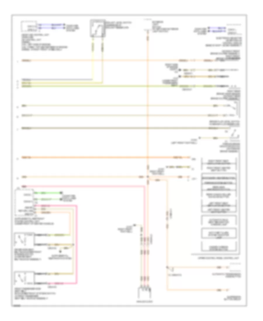 https://portal-diagnostov.com/license.html
Automotive Electricians Portal FZCO
Automotive Electricians Portal FZCO
https://portal-diagnostov.com/license.html
https://portal-diagnostov.com/license.html
Automotive Electricians Portal FZCO
Automotive Electricians Portal FZCOList of elements for Instrument Cluster Wiring Diagram (2 of 2) for Mercedes-Benz E250 Bluetec 4Matic 2014:
- (left front footwell)
- (on right front brake caliper assembly) right front brake wear sensor
- (right side of engine compt) w2
- 30g
- Analog clock
- Anti-theft alarm system indicator lamp
- Automatic child seat recognition warning lamp
- Automatic transmission mode button
- Brake fluid level switch (in brake fluid reservoir)
- Can c h
- Can c l
- Can e h
- Can e l
- Can-c h
- Can-c l
- Computer data lines system
- Coolant level switch (underside of coolant reservoir)
- Driver side seat belt buckle restraint systems switch (in driver seat belt buckle assembly)
- Electronic selector lever module control module (base of shift lever assembly)
- Exterior light switch (w/ network exterior light switch)
- Front passenger side seat belt buckle restraint systems switch (in front passenger seat belt buckle assembly)
- Gss bf
- Gss fa
- Hazard warning system button
- Left front heated seat button
- Left front seat ventilation button
- Lin
- Lin 1
- Me-sfi (me) control unit (gasoline) cdi control unit (diesel) (3.5l: left side of engine) (4.6l turbo: top center rear of engine) (diesel: in right front wheelwell)
- Nca
- Parking brake indicator switch (on parking brake assembly)
- Parking system button
- Rear head restraints button
- Rear window roller sun blind button
- Red
- Return line
- Right front heated seat button
- Right front seat ventilation button
- Right rear brake wear sensor (on right rear brake caliper assembly)
- Stationary heater button
- Suspension button group
- Upper control panel control unit
- W/ airmatic
- W15/2
- W15/7 (right front footwell)
- W19 (under front passenger's seat)
- X138/1-c1
- X157/5-c2
- X55/3-c2
- X55/4-c2
- X62/33-c1
- X62/6-c1
Overhead Console Wiring Diagram, with Sunroof (1 of 2) for Mercedes-Benz E250 Bluetec 4Matic 2014
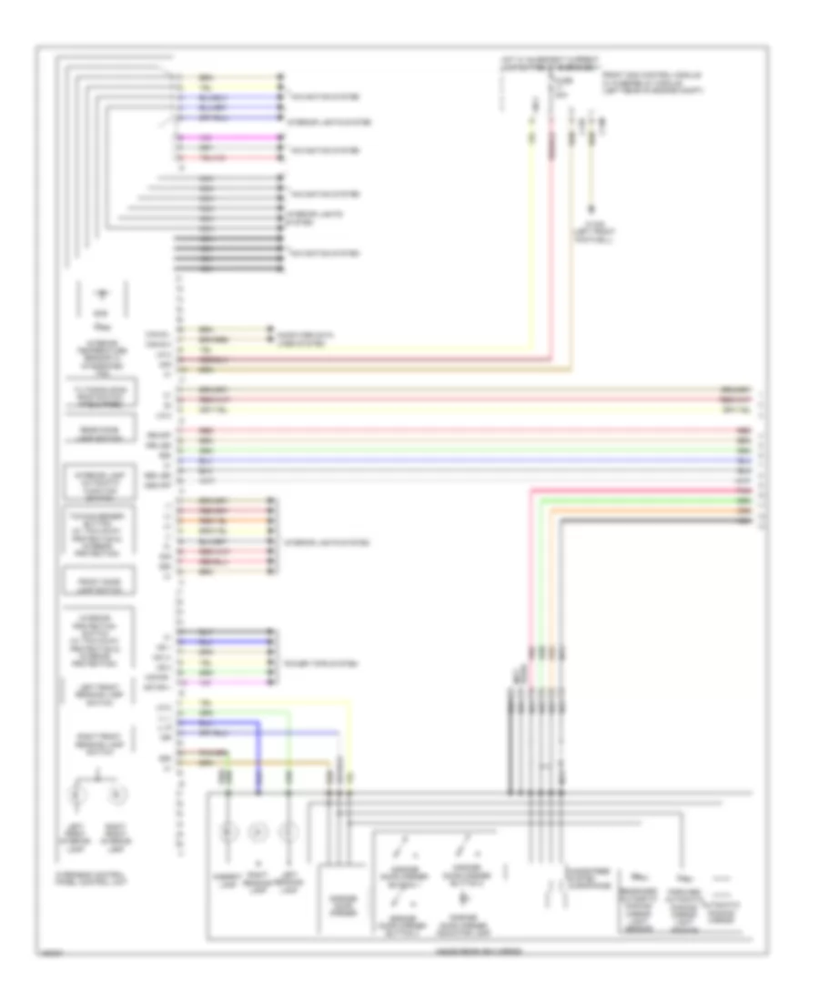 https://portal-diagnostov.com/license.html
Automotive Electricians Portal FZCO
Automotive Electricians Portal FZCO
https://portal-diagnostov.com/license.html
https://portal-diagnostov.com/license.html
Automotive Electricians Portal FZCO
Automotive Electricians Portal FZCOList of elements for Overhead Console Wiring Diagram, with Sunroof (1 of 2) for Mercedes-Benz E250 Bluetec 4Matic 2014:
- (+)
- (-)
- 15r
- 30g
- 58d
- Ambient lamp
- Ass led
- Ass off
- Automatic dimming mirror
- C13d
- C14m
- Can b h
- Can b l
- Computer data lines system
- Forward automatic dimming mirror light sensor
- Front dome lamp switch
- Front sam control module w/ fuse/relay module (left rear of engine compt)
- Fuse 30a
- Garage door opener
- Garage door opener button 1
- Garage door opener button 2
- Garage door opener button 3
- Garage door opener indicator lamp
- Hands-free system microphone
- Hot w/ quiescent current cutout relay energized
- Hs (+)
- Hs 1
- Hs 2
- Inside rearview mirror
- Interior lamp automatic function switch
- Interior lights system
- Interior protection switch (w/ tow-away protection & interior protection)
- Interior temperature sensor w/ integrated fan
- Irs-led
- Irs-off
- Left front interior lamp
- Left front reading lamp switch
- Left reading lamp
- Lin 2
- Ll l
- Ll r
- Motor +
- Motor -
- Navigation system
- Nca
- Overhead control panel control unit
- Pnk
- Power tops system
- Rear dome lamp switch
- Rearward automatic dimming mirror light sensor
- Red
- Right front interior lamp
- Right front reading lamp switch
- Right reading lamp
- Sos
- Tilting/sliding roof switch (if equipped)
- Towing sensor button (w/ tow-away protection & interior protection)
- Used) (not
- W15/5 (left front footwell)
Overhead Console Wiring Diagram, with Sunroof (2 of 2) for Mercedes-Benz E250 Bluetec 4Matic 2014
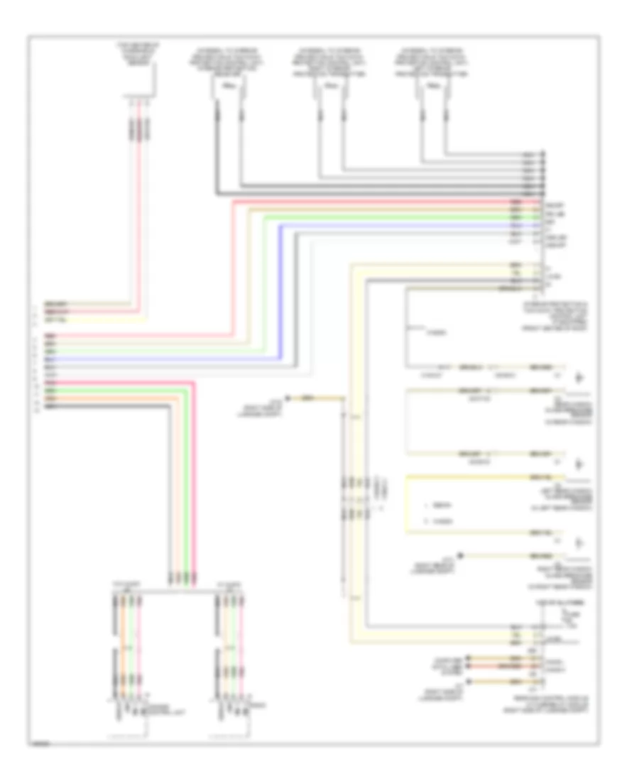 https://portal-diagnostov.com/license.html
Automotive Electricians Portal FZCO
Automotive Electricians Portal FZCO
https://portal-diagnostov.com/license.html
https://portal-diagnostov.com/license.html
Automotive Electricians Portal FZCO
Automotive Electricians Portal FZCOList of elements for Overhead Console Wiring Diagram, with Sunroof (2 of 2) for Mercedes-Benz E250 Bluetec 4Matic 2014:
- (in left rear window)
- (in rear window)
- (integral to interior protection & tow-away protection control unit) interior protection receiver
- (integral to interior protection & tow-away protection control unit) left interior protection transmitter
- (integral to interior protection & tow-away protection control unit) right interior protection transmitter
- (top center of windshield) rain/light sensor
- 58d
- Ass led
- Ass off
- C7i
- C8d
- C9i
- Can b h
- Can b l
- Comand control unit
- Computer data lines system
- Fuse 7.5a
- Gnd
- Hot at all times
- Interior protection & tow-away protection control unit (if equipped) (front center of roof)
- Irs led
- Irs-off
- Left rear window glass breakage sensor
- Lin b4
- Mic 1
- Mic 2
- Nca
- Pnk
- Radio
- Rear sam control module w/ fuse/relay module (right side of luggage compt)
- Rear window glass breakage sensor
- Red
- Right rear window glass breakage sensor (in right rear window)
- Sedan
- Shield
- W/ audio
- W/o audio
- W7 (right side of luggage compt)
- W7/1 (right rear of luggage compt)
- W7/8 (right side of luggage compt)
- Wagon
- X18/2-c1
- X42/28-c1
- X8/45-c4
- X8/46-c1
- X8/47-c2
Overhead Console Wiring Diagram, without Sunroof (1 of 2) for Mercedes-Benz E250 Bluetec 4Matic 2014
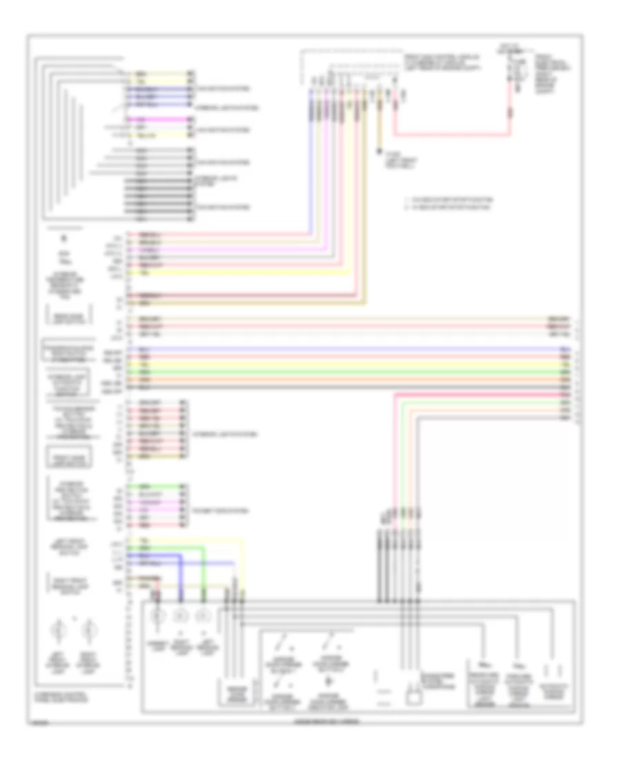 https://portal-diagnostov.com/license.html
Automotive Electricians Portal FZCO
Automotive Electricians Portal FZCO
https://portal-diagnostov.com/license.html
https://portal-diagnostov.com/license.html
Automotive Electricians Portal FZCO
Automotive Electricians Portal FZCOList of elements for Overhead Console Wiring Diagram, without Sunroof (1 of 2) for Mercedes-Benz E250 Bluetec 4Matic 2014:
- (+)
- (-)
- 12v
- 15r
- 30g
- 58d
- Ambient lamp
- Ass led
- Ass off
- Automatic dimming mirror
- C13d
- C14m
- C16s
- Forward automatic dimming mirror light sensor
- Front dome lamp switch
- Front electrical prefuse box (right rear of engine compt)
- Front sam control module w/ fuse/relay module (left rear of engine compt)
- Fuse 150a
- Garage door opener
- Garage door opener button 1
- Garage door opener button 2
- Garage door opener button 3
- Garage door opener indicator lamp
- Hands-free system microphone
- Hot at all times
- Inside rearview mirror
- Interior lamp automatic function switch
- Interior lights system
- Interior protection switch (w/ tow-away protection & interior protection)
- Interior temperature sensor w/ integrated fan
- Irs-led
- Irs-off
- Left front interior lamp
- Left front reading lamp switch
- Left reading lamp
- Lin 2
- Ll l
- Ll r
- Mr7
- Navigation system
- Nca
- Ntc (+)
- Ntc (-)
- Ntc +
- Ntc -
- Overhead control panel electronics
- Panoramic sliding roof switch (if equipped)
- Pnk
- Power tops system
- Rear dome lamp switch
- Rearward automatic dimming mirror light sensor
- Red
- Right front interior lamp
- Right front reading lamp switch
- Right reading lamp
- Sig
- Sig il
- Sos
- Towing sensor button (w/ tow-away protection & interior protection)
- Used) (not
- W/ eco start/stop function
- W/o eco start/stop function
- W15/5 (left front footwell)
Overhead Console Wiring Diagram, without Sunroof (2 of 2) for Mercedes-Benz E250 Bluetec 4Matic 2014
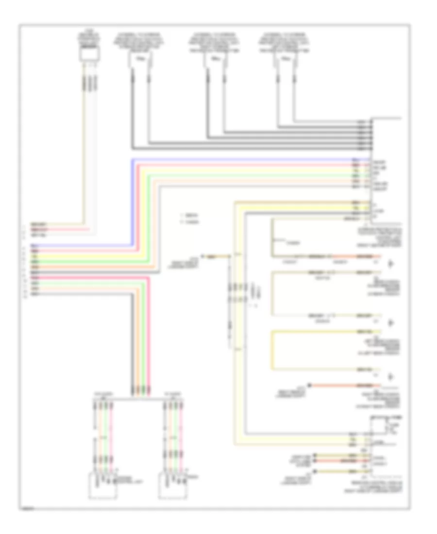 https://portal-diagnostov.com/license.html
Automotive Electricians Portal FZCO
Automotive Electricians Portal FZCO
https://portal-diagnostov.com/license.html
https://portal-diagnostov.com/license.html
Automotive Electricians Portal FZCO
Automotive Electricians Portal FZCOList of elements for Overhead Console Wiring Diagram, without Sunroof (2 of 2) for Mercedes-Benz E250 Bluetec 4Matic 2014:
- (in left rear window)
- (in rear window)
- (integral to interior protection & tow-away protection control unit) interior protection receiver
- (integral to interior protection & tow-away protection control unit) left interior protection transmitter
- (integral to interior protection & tow-away protection control unit) right interior protection transmitter
- (top center of windshield) rain/light sensor
- 58d
- Ass led
- Ass off
- C7i
- C8d
- C9i
- Can b h
- Can b l
- Comand control unit
- Computer data lines system
- Fuse 7.5a
- Gnd
- Hot at all times
- Interior protection & tow-away protection control unit (if equipped) (front center of roof)
- Irs led
- Irs-off
- Left rear window glass breakage sensor
- Lin b4
- Mic 1
- Mic 2
- Nca
- Pnk
- Radio
- Rear sam control module w/ fuse/relay module (right side of luggage compt)
- Rear window glass breakage sensor
- Red
- Right rear window glass breakage sensor (in right rear window)
- Sedan
- Shield
- W/ audio
- W/o audio
- W7 (right side of luggage compt)
- W7/1 (right rear of luggage compt)
- W7/8 (right side of luggage compt)
- Wagon
- X18/2-c1
- X42/28-c1
- X8/2-c1
- X8/45-c4
- X8/46-c1
- X8/47-c2
INTERIOR LIGHTS
Courtesy Lamps Wiring Diagram (1 of 3) for Mercedes-Benz E250 Bluetec 4Matic 2014
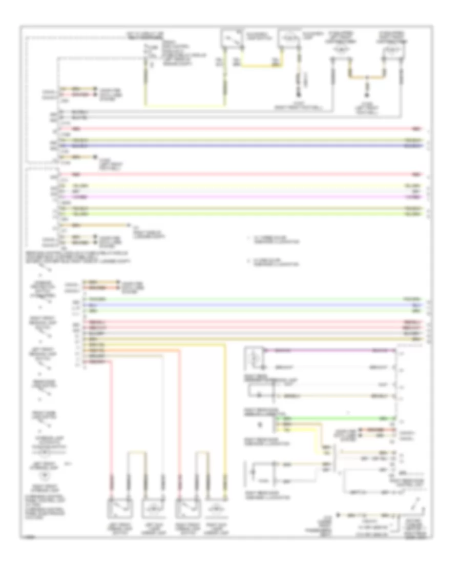 https://portal-diagnostov.com/license.html
Automotive Electricians Portal FZCO
Automotive Electricians Portal FZCO
https://portal-diagnostov.com/license.html
https://portal-diagnostov.com/license.html
Automotive Electricians Portal FZCO
Automotive Electricians Portal FZCOList of elements for Courtesy Lamps Wiring Diagram (1 of 3) for Mercedes-Benz E250 Bluetec 4Matic 2014:
- (+)
- (-)
- (if equipped) left front footwell lamp
- (if equipped) right front footwell lamp
- 11c
- 30g
- 58d
- C14m
- C16s
- C17c
- C19i
- C1v
- C22i
- C5h
- C6hd
- C7i
- C9i
- Can b h
- Can b l
- Computer data lines system
- Front dome lamp switch
- Front sam control module w/ fuse & relay module (left rear of engine compt)
- Fuse 7.5a
- Glove box lamp
- Glove box lamp switch
- Hot w/ circuit 15r relay energized
- Interior lamp automatic function switch
- Interior protection switch (if equipped)
- Left front
- Left front interior lamp
- Left front mirror lamp switch
- Left sun visor mirror lamp
- Ll l
- Ll r
- Overhead control panel control unit (w/ can) overhead control panel electronics (w/o can)
- Reading lamp switch
- Rear dome lamp switch
- Rear sam control module w/ fuse & relay module (convertible: in spare wheelwell) (except convertible: right side of luggage compt)
- Red
- Right front
- Right front interior lamp
- Right front mirror lamp switch
- Right rear door ambiance illumination
- Right rear door control unit
- Right rear door exit & warning lamp
- Right rear door handle illumination
- Right rear door lock
- Right sun visor mirror lamp
- Rotary tumbler switch
- Sig
- W/ keyless go
- W/ one color ambiance illumination
- W/ three color ambiance illumination
- W/o keyless go
- W15/5 (left front footwell)
- W15/7 (right front footwell)
- W19 (under front passenger's seat)
- W7 (right side of luggage compt)
- X29/1-c1
- X35/4-c1
Courtesy Lamps Wiring Diagram (2 of 3) for Mercedes-Benz E250 Bluetec 4Matic 2014
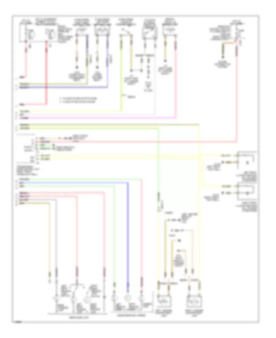 https://portal-diagnostov.com/license.html
Automotive Electricians Portal FZCO
Automotive Electricians Portal FZCO
https://portal-diagnostov.com/license.html
https://portal-diagnostov.com/license.html
Automotive Electricians Portal FZCO
Automotive Electricians Portal FZCOList of elements for Courtesy Lamps Wiring Diagram (2 of 3) for Mercedes-Benz E250 Bluetec 4Matic 2014:
- (if equipped) left rear footwell lamp
- (if equipped) right rear footwell lamp
- (if equipped) tailgate contact switch
- (left center rear of roof) w48
- (right front footwell) w15/1
- (sedan) trunk lid ambient lamp
- Ambient lamp
- C15h
- Can e1 h
- Can e1 l c4
- Computer data lines system
- Front electrical prefuse box (right rear of engine compt)
- Fuse 150a
- Fuse 5a
- Hot at all times
- Hot w/ quiescent current cutout relay energized
- Ig1
- Inside rearview mirror
- Left front illuminated door sill molding (if equipped)
- Left luggage compartment lamp
- Left reading lamp
- Left rear reading lamp
- Left rear reading lamp switch
- Mr7
- Power distribution system
- Rear dome lamp
- Rear interior lamp
- Rear sam control module w/ fuse & relay module (right side of luggage compt)
- Red
- Right front illuminated door sill molding (if equipped)
- Right luggage compartment lamp
- Right reading lamp
- Right rear reading lamp
- Right rear reading lamp switch
- Sedan
- Sedan wagon
- Sig
- Tailgate external operation switch
- Transmission mode control unit (right front upper footwell)
- W/ eco start/stop system
- W/o eco start/stop system
- W13/1 (left "c" pillar)
- W15/1 (right front footwell)
- W15/2 (left front footwell)
- W18 (under driver's seat)
- W19 (under front passenger's seat)
- W48/1
- W7 (right side of luggage compt)
- W7/1 (right rear of luggage compt)
- Wagon
- X55/3-c7
- X55/4-c7
- X8/47-c1
Courtesy Lamps Wiring Diagram (3 of 3) for Mercedes-Benz E250 Bluetec 4Matic 2014
 https://portal-diagnostov.com/license.html
Automotive Electricians Portal FZCO
Automotive Electricians Portal FZCO
https://portal-diagnostov.com/license.html
https://portal-diagnostov.com/license.html
Automotive Electricians Portal FZCO
Automotive Electricians Portal FZCOList of elements for Courtesy Lamps Wiring Diagram (3 of 3) for Mercedes-Benz E250 Bluetec 4Matic 2014:
- (+)
- (-)
- C9i
- Can b h
- Can b l
- Computer data lines
- Computer data lines system
- Gnd
- Left front door ambiance illumination
- Left front door control unit
- Left front door exit & warning lamp
- Left front door handle illumination
- Left front door lock
- Left rear door ambiance illumination
- Left rear door control unit
- Left rear door exit & warning lamp
- Left rear door handle illumination
- Left rear door lock
- Right front door ambiance illumination
- Right front door control unit
- Right front door exit & warning lamp
- Right front door handle illumination
- Right front door lock
- Rotary tumbler switch
- Sig
- W/ keyless go
- W/ one color ambience illumination
- W/ three color ambience illumination
- W/o keyless go
- W18 (under driver's seat)
- X35/3-c1
Instrument Illumination Wiring Diagram (1 of 2) for Mercedes-Benz E250 Bluetec 4Matic 2014
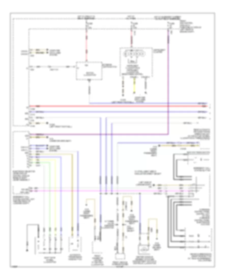 https://portal-diagnostov.com/license.html
Automotive Electricians Portal FZCO
Automotive Electricians Portal FZCO
https://portal-diagnostov.com/license.html
https://portal-diagnostov.com/license.html
Automotive Electricians Portal FZCO
Automotive Electricians Portal FZCOList of elements for Instrument Illumination Wiring Diagram (1 of 2) for Mercedes-Benz E250 Bluetec 4Matic 2014:
- (left side of luggage compt) w6
- 15g
- 30g
- 58d
- Automatic transmission mode button
- C11c
- C14m
- C16s
- C17c
- C19i
- C22i
- C9g
- Can b h
- Can b l
- Can c h
- Can c l
- Can e2 h
- Can e2 l
- Center console armrest stowage compartment switch & controls illumination
- Computer data lines system
- Electronic selector lever module control module (base of shift lever assembly)
- Emergency call system button
- Emergency call system control unit (center front of luggage compt)
- Exterior lights switch
- Front cigarette lighter w/ ashtray illumination
- Front sam control module w/ fuse & relay module (left rear of engine compt)
- Front vehicle interior power outlet
- Fuse 5a
- Fuse 7.5a
- Hot at all times
- Hot w/ circuit 15 relay energized
- Hot w/ quiescent current cutout relay energized
- Info led
- Instrument cluster
- Instrument illumination & instrument illumination brightness control
- Mb-info & breakdown assistance button (w/ tele aid emergency call system)
- Module for direct select
- Nca
- Overhead control panel control unit (w/ can) overhead control panel electronics (w/o can)
- Rear automatic air conditioning operating unit (w/ air outlet symbol illumination & thermotronic)
- Red
- Shift gate symbol illumination
- Switch illumination
- Two way radio switch
- W/ intelligent servo
- W/ three color ambiance illumination
- W/o direct select
- W15/5 (left front footwell)
- W18 (under driver's seat)
- W19 (under front passenger's seat)
- Ws led
- X138/1-c2
- X18/37-c1
- X18/46
- X29/5
- X83/11-c1
Instrument Illumination Wiring Diagram (2 of 2) for Mercedes-Benz E250 Bluetec 4Matic 2014
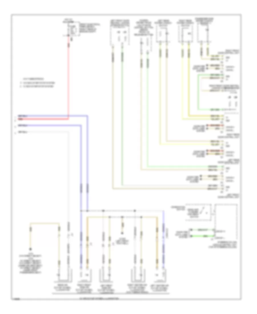 https://portal-diagnostov.com/license.html
Automotive Electricians Portal FZCO
Automotive Electricians Portal FZCO
https://portal-diagnostov.com/license.html
https://portal-diagnostov.com/license.html
Automotive Electricians Portal FZCO
Automotive Electricians Portal FZCOList of elements for Instrument Illumination Wiring Diagram (2 of 2) for Mercedes-Benz E250 Bluetec 4Matic 2014:
- (wagon) driver trunk lid/liftgate control button (sedan) trunk lid release button
- 58d
- Can b h
- Can b l
- Can e1 h
- Can e1 l
- Combination switch
- Computer data lines system
- Front electrical prefuse box (right rear of engine compt)
- Fuse 150a
- Headlamp flasher/ high beam switch
- Hot at all times
- Left center air outlet symbol illumination
- Left front door central locking interior switch
- Left front door control unit
- Left front side air outlet symbol illumination
- Left rear door control unit
- Left rear power window switch
- Mr7
- Passenger side power window switch
- Rear air outlet symbol illumination
- Red
- Right center air outlet symbol illumination (w/o thermotronic)
- Right front door central locking interior switch
- Right front door control unit
- Right front side air outlet symbol illumination
- Right rear door control unit
- Right rear power window switch
- Steering column module control unit (top of steering column)
- W/ air outlet symbol illumination
- W/ eco start/stop system
- W/o eco start/stop system
- W/o thermotronic
- W15/5 (left front footwell)
- W18 (w/o direct select) w19 (w/ direct select) (w/o direct select: under driver's seat) (w/ direct select: under front passenger's seat)
- X157/1-c2
MEMORY SYSTEMS
Driver"s Memory Seat Wiring Diagram (1 of 2) for Mercedes-Benz E250 Bluetec 4Matic 2014
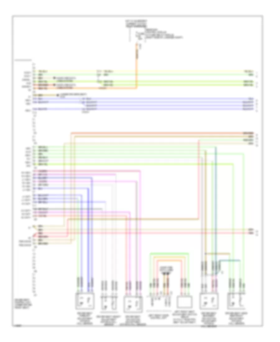 https://portal-diagnostov.com/license.html
Automotive Electricians Portal FZCO
Automotive Electricians Portal FZCO
https://portal-diagnostov.com/license.html
https://portal-diagnostov.com/license.html
Automotive Electricians Portal FZCO
Automotive Electricians Portal FZCOList of elements for Driver"s Memory Seat Wiring Diagram (1 of 2) for Mercedes-Benz E250 Bluetec 4Matic 2014:
- (under driver's seat) w18
- C12i
- Can b h
- Can b l
- Can-b h
- Can-b l
- Computer data lines system
- Driver seat backrest inclination adjustment motor & hall sensor
- Driver seat control unit (under driver front seat)
- Driver seat fore/aft adjustment motor & hall sensor
- Driver seat head restraint adjustment motor & hall sensor
- Driver seat height adjustment motor & hall sensor
- Driver seat inclination adjustment motor & hall sensor
- Fds can b
- Fuse 25a
- Hot w/ quiescent current cutout relay energized
- Hs(+)
- Hs(-)
- Hv hs(+)
- Hv hs(-)
- Hv mot+
- Hv mot-
- Left front door control unit
- Left front seat adjustment switch group (w/ fully electric seat adjustment)
- Lin bus
- Lv hs(+)
- Lv hs(-)
- Lv mot+
- Lv mot-
- Mk+
- Ml+
- Ml/k
- Mls
- Mls h
- Mls v
- Nv hs(+)
- Nv hs(-)
- Nv mot+
- Nv mot-
- Rear sam control module w/ fuse/ relay module (right side of luggage compt)
- Red
- X18-c1
Driver"s Memory Seat Wiring Diagram (2 of 2) for Mercedes-Benz E250 Bluetec 4Matic 2014
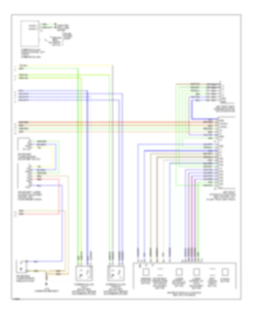 https://portal-diagnostov.com/license.html
Automotive Electricians Portal FZCO
Automotive Electricians Portal FZCO
https://portal-diagnostov.com/license.html
https://portal-diagnostov.com/license.html
Automotive Electricians Portal FZCO
Automotive Electricians Portal FZCOList of elements for Driver"s Memory Seat Wiring Diagram (2 of 2) for Mercedes-Benz E250 Bluetec 4Matic 2014:
- (+)
- (-)
- 12v
- 12v (+)
- 58d
- Can-b h
- Can-b l
- Can-e1 h
- Can-e1 l
- Computer data lines system
- Cruise control lever
- Driver dynamic multicontour seat button group
- Driver seat lumbar support adjustment control unit (in driver seat back)
- Driver seat lumbar support adjustment switch
- Driver seat lumbar support pneumatic pump
- Driver seat side bolster air cushion adjustment button
- Dynamic button
- End
- Left front dynamic multicontour seat control unit (in left front seat back)
- Left front seat massage function actuator motor
- Lumbar support +/- adjustment button
- Lumbar support up/ down adjustment button
- Message function button
- Nca
- Red
- Resume from memory switch
- Seat cushion length button
- Sig
- Steering column in/out adjustment motor & hall sensor (on steering column)
- Steering column module control unit (top of steering column)
- Steering column up/down adjustment motor & hall sensor (on steering column)
- W18 (under driver's seat)
Memory Mirrors Wiring Diagram for Mercedes-Benz E250 Bluetec 4Matic 2014
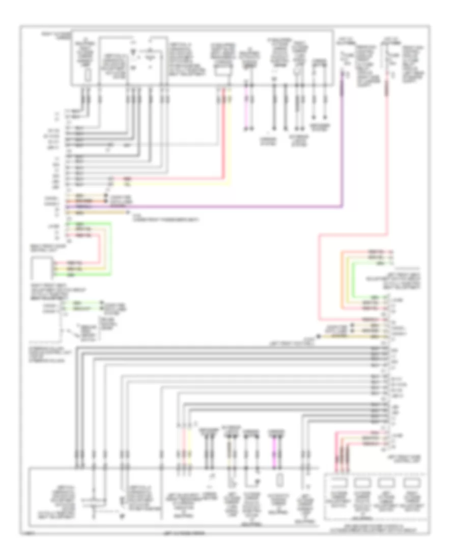 https://portal-diagnostov.com/license.html
Automotive Electricians Portal FZCO
Automotive Electricians Portal FZCO
https://portal-diagnostov.com/license.html
https://portal-diagnostov.com/license.html
Automotive Electricians Portal FZCO
Automotive Electricians Portal FZCOList of elements for Memory Mirrors Wiring Diagram for Mercedes-Benz E250 Bluetec 4Matic 2014:
- (+)
- (if equipped) automatic dimming mirror
- (if equipped) outside mirror fold in/ fold out electric motor
- (if equipped) right blind spot assist readiness & warning indicator
- (if equipped) right outside mirror ambient lamp
- Automatic dimming mirror (if equipped)
- C3i
- C7i
- Can-b h
- Can-b l
- Can-e1 h
- Can-e1 l
- Computer data lines system
- Cruise control lever
- Defogger system
- Driver side power window & outside mirror adjustment switch group
- Exterior lights system
- Front sam control module w/ fuse/ relay module (left rear of engine compt)
- Fuse 30a
- Hot at all times
- Led
- Led 31
- Left blind spot assist readiness & warning indicator (if equipped)
- Left front door control unit
- Left front seat adjustment switch group (w/ fully electric seat adjustment)
- Left outside mirror
- Left outside mirror adjustment switch
- Left outside mirror ambient lamp (if equipped)
- Left outside mirror turn signal lamp
- Lin b5
- Mirror heater
- Mirrors system
- Outside mirror adjustment switch
- Outside mirror fold in/ fold out electric motor (if equipped)
- Outside mirror fold in/ fold out switch (if equipped)
- Pnk
- Rear sam control module front w/ fuse/ relay module (right side of luggage compt)
- Red
- Resume from memory switch
- Right front door control unit
- Right front seat adjustment switch group (w/ fully electric seat adjustment)
- Right outside mirror
- Right outside mirror adjustment switch
- Right outside mirror turn signal lamp
- Sig
- Steering column module control unit (top of steering column)
- Sv m1
- Sv m1m2
- Sv m2
- Vertical & horizontal inclination adjustment actuator & potentiometer (w/ fully electric seat adjustment)
- Vertical & horizontal inclination adjustment actuator motor
- Vertical & horizontal inclination adjustment actuator potentiometer
- Vertical horizontal inclination adjustment actuator motor (w/ fully electric seat adjustment)
- W15/2 (left front footwell)
- W19 (under front passenger's seat)
Passenger"s Memory Seat Wiring Diagram (1 of 2) for Mercedes-Benz E250 Bluetec 4Matic 2014
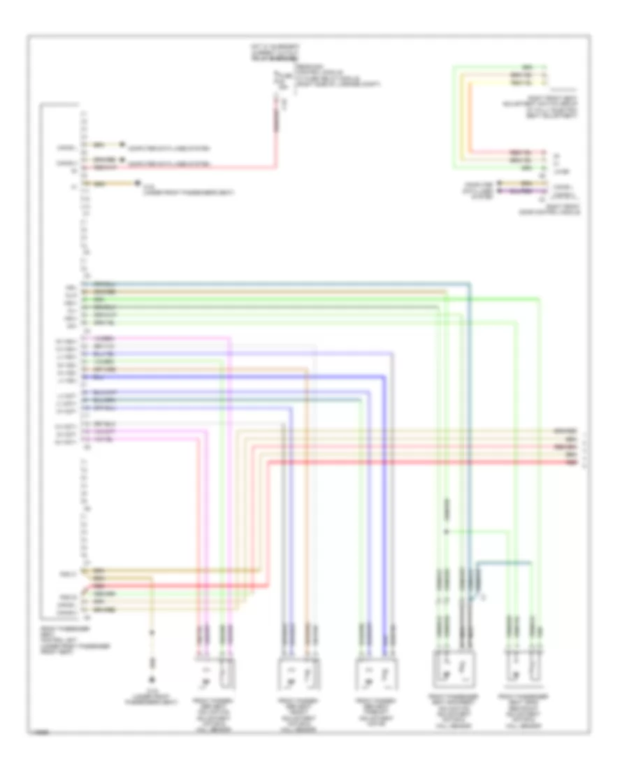 https://portal-diagnostov.com/license.html
Automotive Electricians Portal FZCO
Automotive Electricians Portal FZCO
https://portal-diagnostov.com/license.html
https://portal-diagnostov.com/license.html
Automotive Electricians Portal FZCO
Automotive Electricians Portal FZCOList of elements for Passenger"s Memory Seat Wiring Diagram (1 of 2) for Mercedes-Benz E250 Bluetec 4Matic 2014:
- C12i
- Can-b h
- Can-b l
- Computer data lines system
- Fds 30
- Fds 31
- Front passen- ger seat fore/aft adjustment motor
- Front passen- ger seat height adjustment motor & hall sensor
- Front passen- ger seat inclination adjustment motor & hall sensor
- Front passenger seat backrest inclination adjustment motor & hall sensor
- Front passenger seat control unit (under front passenger front seat)
- Front passenger seat head restraint adjustment motor & hall sensor
- Fuse 25a
- Hot w/ quiescent current cutout relay energized
- Hs(+)
- Hs(-)
- Hv hs(+)
- Hv hs(-)
- Hv mot+
- Hv mot-
- Lin b5
- Lv hs(+)
- Lv hs(-)
- Lv mot+
- Lv mot-
- Mk+
- Ml+
- Ml/k
- Nca
- Nv hs(+)
- Nv hs(-)
- Nv mot+
- Nv mot-
- Rear sam control module w/ fuse/ relay module (right side of luggage compt)
- Red
- Right front door control module
- Right front seat adjustment switch group (w/ fully electric seat adjustment)
- W19 (under front passenger's seat)
Passenger"s Memory Seat Wiring Diagram (2 of 2) for Mercedes-Benz E250 Bluetec 4Matic 2014
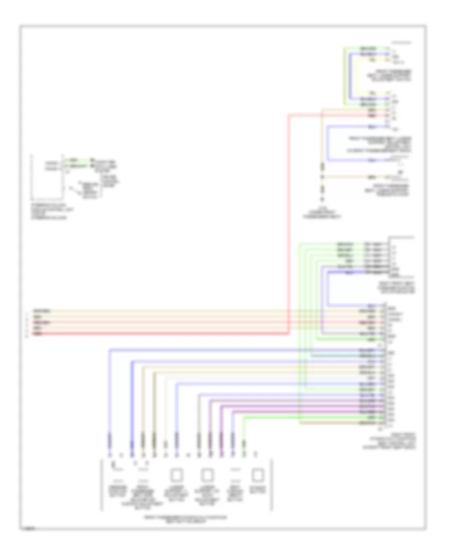 https://portal-diagnostov.com/license.html
Automotive Electricians Portal FZCO
Automotive Electricians Portal FZCO
https://portal-diagnostov.com/license.html
https://portal-diagnostov.com/license.html
Automotive Electricians Portal FZCO
Automotive Electricians Portal FZCOList of elements for Passenger"s Memory Seat Wiring Diagram (2 of 2) for Mercedes-Benz E250 Bluetec 4Matic 2014:
- (+)
- (-)
- 12v
- 12v (+)
- 58d
- Can-b h
- Can-b l
- Can-e1 h
- Can-e1 l
- Computer data lines system
- Cruise control lever
- Dynamic button
- End
- Front passenger dynamic multicontour seat button group
- Front passenger seat lumbar support adjustment control unit (in front passenger seat back)
- Front passenger seat lumbar support adjustment switch
- Front passenger seat lumbar support pneumatic pump
- Front passenger seat side bolster air cushion adjustment button
- Lumbar support +/- adjustment button
- Lumbar support up/ down adjustment button
- Message function button
- Nca
- Red
- Resume from memory switch
- Right front dynamic multicontour seat control unit (in right front seat back)
- Right front seat massage function actuator motor
- Seat cushion length button
- Sig
- Steering column module control unit (top of steering column)
- W19 (under front passenger's seat)
NAVIGATION
All Around Vision Camera Wiring Diagram for Mercedes-Benz E250 Bluetec 4Matic 2014
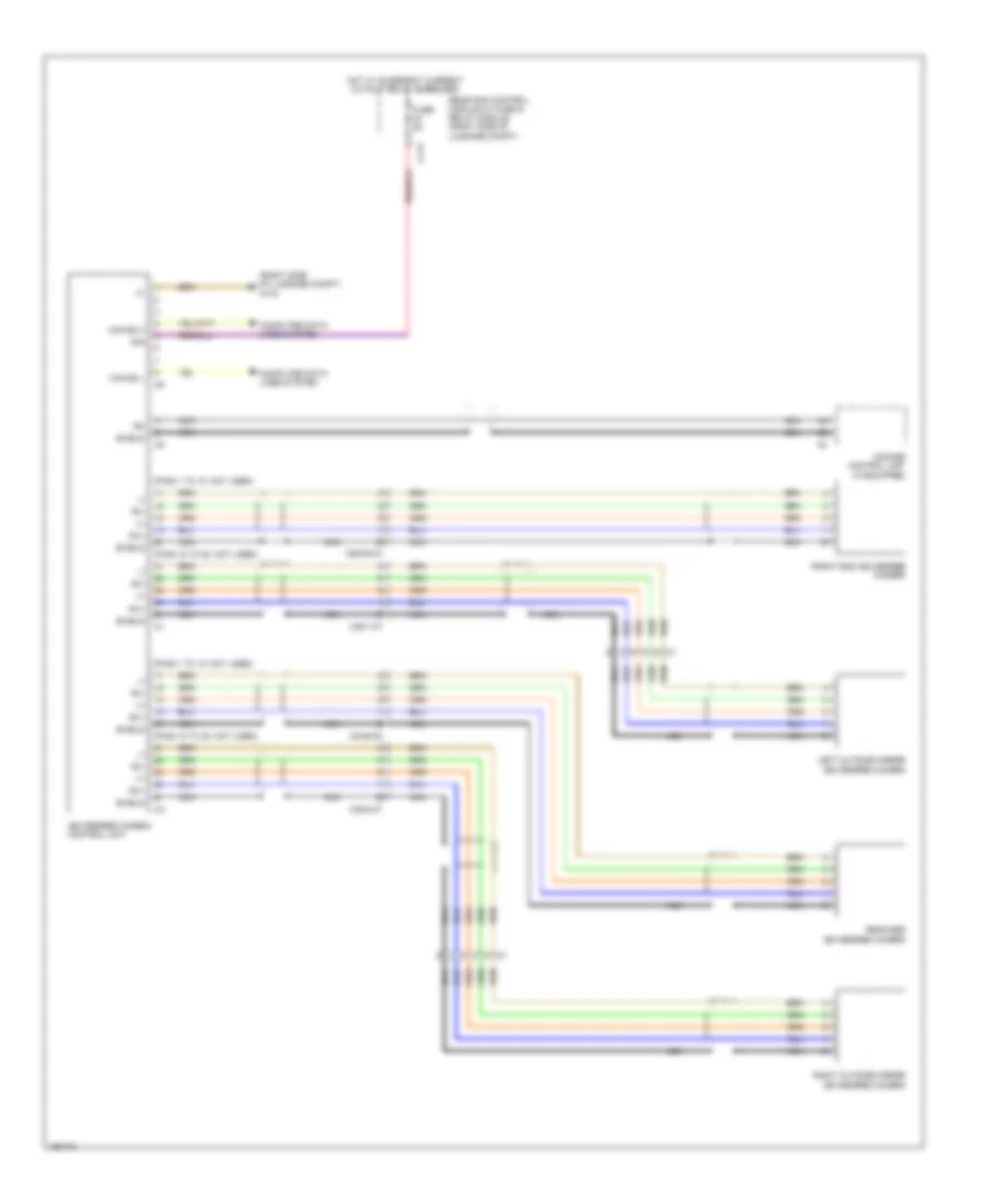 https://portal-diagnostov.com/license.html
Automotive Electricians Portal FZCO
Automotive Electricians Portal FZCO
https://portal-diagnostov.com/license.html
https://portal-diagnostov.com/license.html
Automotive Electricians Portal FZCO
Automotive Electricians Portal FZCOList of elements for All Around Vision Camera Wiring Diagram for Mercedes-Benz E250 Bluetec 4Matic 2014:
- (+)
- (-)
- (pins 1 to 10: not used)
- (pins 15 to 20: not used)
- (right side of luggage compt) w7/8
- 30g
- 360 degree camera control unit
- C11t
- Can e2 h
- Can e2 l
- Comand control unit (if equipped)
- Computer data lines system
- Front end 360 degree camera
- Fuse 5a
- Hot w/ quiescent current cutout relay energized
- Left outside mirror 360 degree camera
- Nca
- Rear end 360 degree camera
- Rear sam control module w/ fuse & relay module (right side of luggage compt)
- Right outside mirror 360 degree camera
- Rx+
- Rx-
- Shield
- X26/38-c3
- X35/1-c7
- X35/2-c7
- X8/46-c5
Blind Spot Information System Wiring Diagram for Mercedes-Benz E250 Bluetec 4Matic 2014
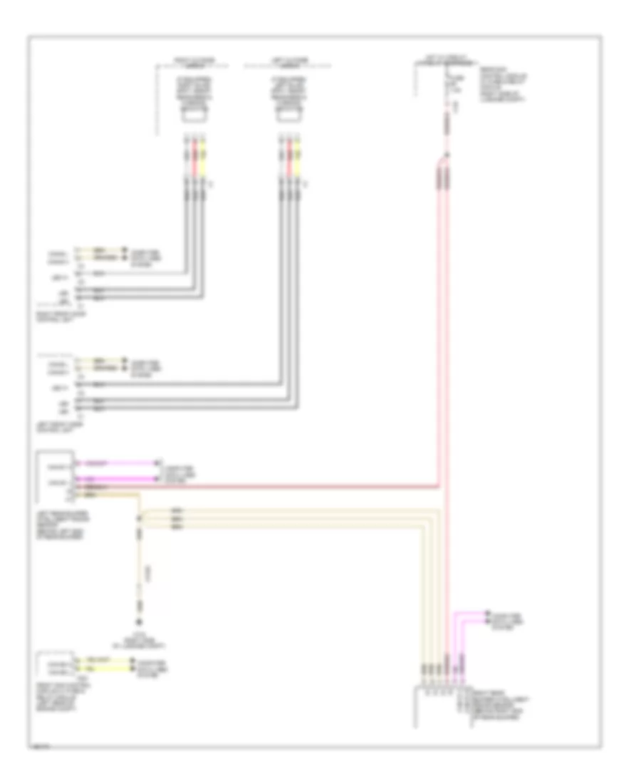 https://portal-diagnostov.com/license.html
Automotive Electricians Portal FZCO
Automotive Electricians Portal FZCO
https://portal-diagnostov.com/license.html
https://portal-diagnostov.com/license.html
Automotive Electricians Portal FZCO
Automotive Electricians Portal FZCOList of elements for Blind Spot Information System Wiring Diagram for Mercedes-Benz E250 Bluetec 4Matic 2014:
- (if equipped) left blind spot assist readiness & warning indicator
- (if equipped) right blind spot assist readiness & warning indicator
- C12i
- C22i
- Can e1 h
- Can e1 l
- Can e2 h
- Can e2 l
- Can-b h
- Can-b l
- Computer data lines system
- Front sam control module w/ fuse & relay module (left rear of engine compt)
- Fuse 7.5a
- Hot w/ circuit 15 relay energized
- Led
- Led 31
- Left front door control unit
- Left outside mirror
- Left rear bumper intelligent radar sensor (behind left end of rear bumper)
- Rear sam control module w/ fuse & relay module (right side of luggage compt)
- Red
- Right front door control unit
- Right outside mirror
- Right rear bumper intelligent radar sensor (behind right end of rear bumper)
- W7/8 (right side of luggage compt)
- X172/2
Emergency Call Wiring Diagram for Mercedes-Benz E250 Bluetec 4Matic 2014
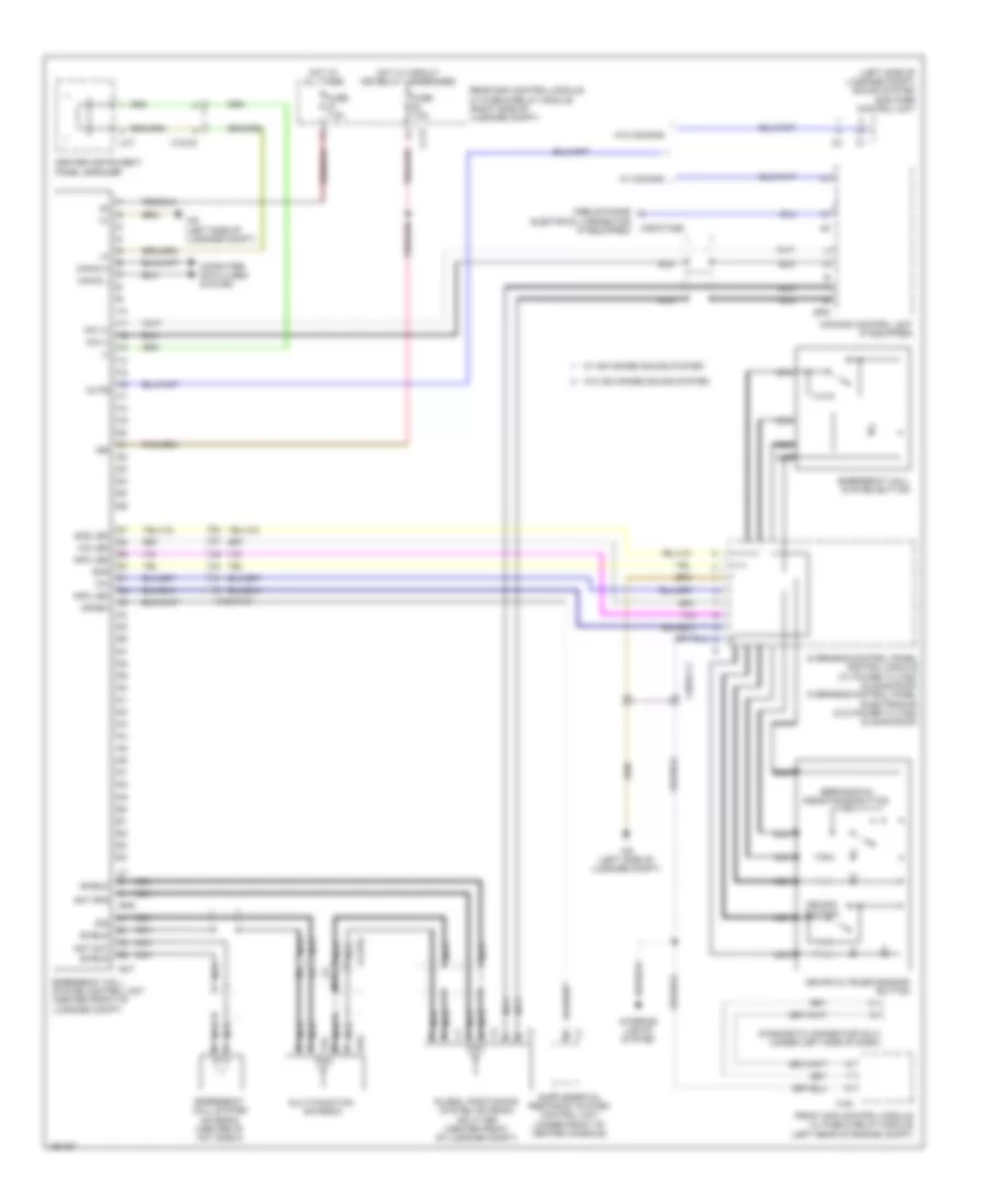 https://portal-diagnostov.com/license.html
Automotive Electricians Portal FZCO
Automotive Electricians Portal FZCO
https://portal-diagnostov.com/license.html
https://portal-diagnostov.com/license.html
Automotive Electricians Portal FZCO
Automotive Electricians Portal FZCOList of elements for Emergency Call Wiring Diagram for Mercedes-Benz E250 Bluetec 4Matic 2014:
- (+)
- (-)
- (left side of luggage compt) sound system amplifier control unit
- 15r
- Ant gps
- Ant not
- Breakdown assistance button
- C1 s
- C11t
- C19i
- Can-d h
- Can-d l
- Center instrument panel speaker
- Comand control unit (if equipped)
- Computer data lines system
- Crash
- Diagnostic connector (dlc) (under left side of dash)
- Emergency call system antenna (center of hat shelf)
- Emergency call system button
- Emergency call system control unit (center front of luggage compt)
- Front sam control module w/ fuse & relay module (left rear of engine compt)
- Fuse 7.5a
- Global positioning system antenna splitter (center front of luggage compt)
- Gps
- Hot at all times
- Hot w/ circuit 15r relay 1 energized
- Info led
- Interior lights system
- Lct
- Mb-info & telediagnosis button
- Mb-info button
- Mic (+)
- Mic (-)
- Mobile phone electrical connector (if equipped)
- Multi-function antenna
- Mute
- Nca
- Nca s
- Nca x
- Not
- Overhead control panel control module (w/ power tilting/ sliding roof) overhead control panel electronics (w/o power tilting/ sliding roof)
- Rear sam control module w/ fuse & relay module (right side of luggage compt)
- Shield
- Sig
- Sos
- Sos led
- Tel
- W/ advanced sound system
- W/ comand
- W/o advanced sound system
- W/o comand
- W6 (left side of luggage compt)
- Ws led
- X1-gps
- X18-c2
- X18/37-c1
- X39/37-c2b
Multifunction Camera Wiring Diagram for Mercedes-Benz E250 Bluetec 4Matic 2014
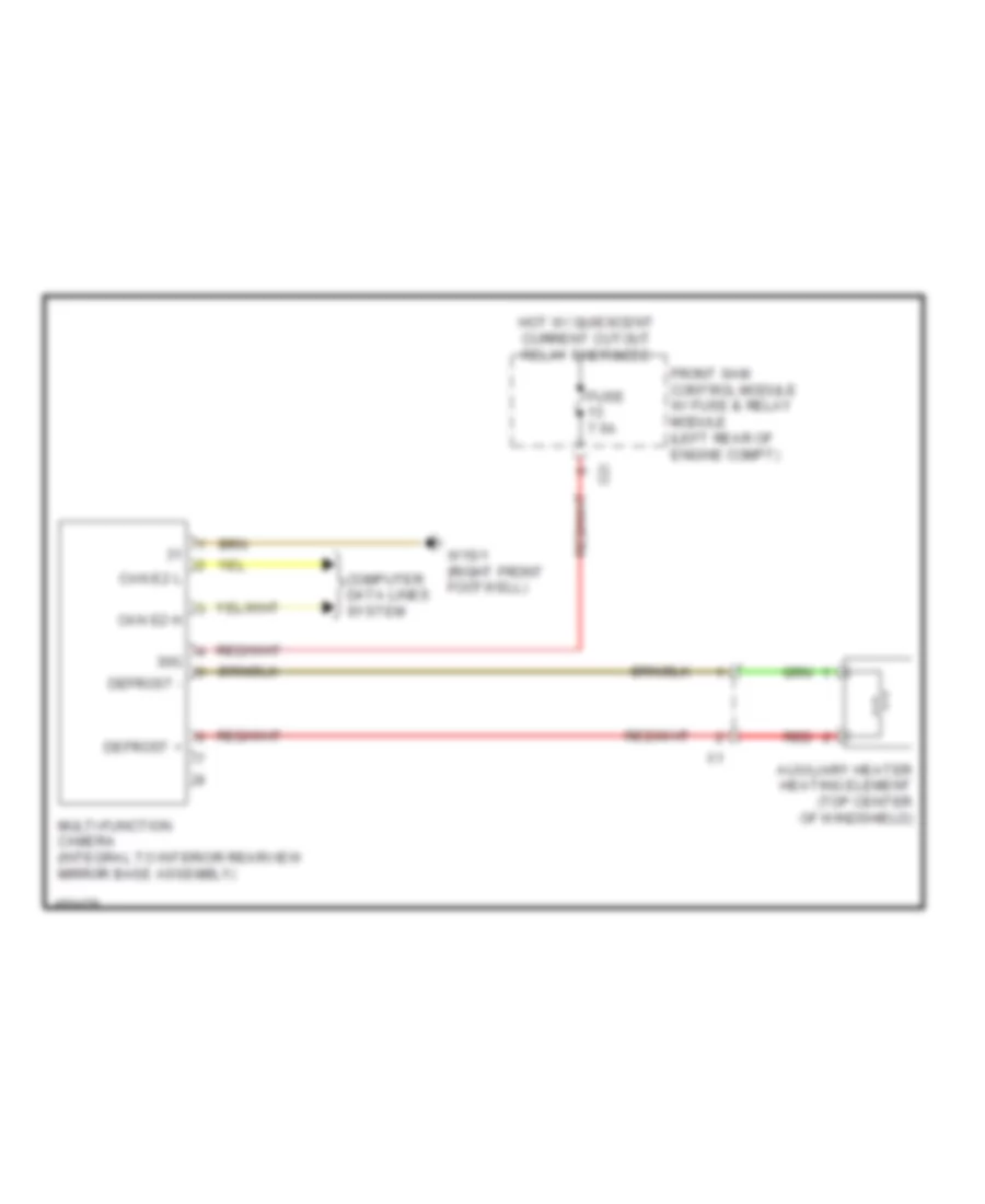 https://portal-diagnostov.com/license.html
Automotive Electricians Portal FZCO
Automotive Electricians Portal FZCO
https://portal-diagnostov.com/license.html
https://portal-diagnostov.com/license.html
Automotive Electricians Portal FZCO
Automotive Electricians Portal FZCOList of elements for Multifunction Camera Wiring Diagram for Mercedes-Benz E250 Bluetec 4Matic 2014:
- 30g
- Auxiliary heater heating element (top center of windshield)
- C2i
- Can e2 h
- Can e2 l
- Computer data lines system
- Defrost +
- Defrost -
- Front sam control module w/ fuse & relay module (left rear of engine compt)
- Fuse 7.5a
- Hot w/ quiescent current cutout relay energized
- Multi-function camera (integral to interior rearview mirror base assembly)
- Red
- W15/1 (right front footwell)
Navigation Wiring Diagram for Mercedes-Benz E250 Bluetec 4Matic 2014
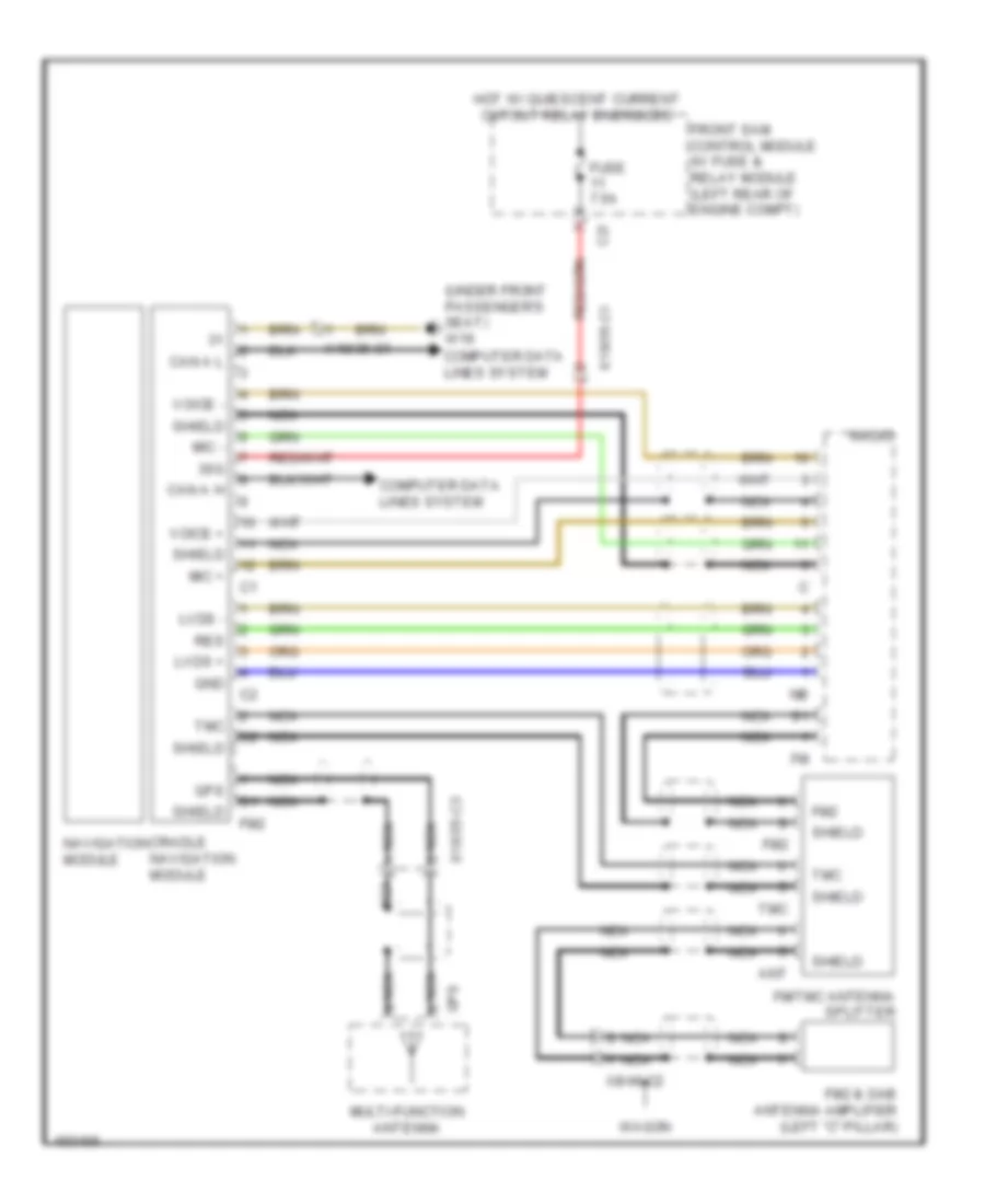 https://portal-diagnostov.com/license.html
Automotive Electricians Portal FZCO
Automotive Electricians Portal FZCO
https://portal-diagnostov.com/license.html
https://portal-diagnostov.com/license.html
Automotive Electricians Portal FZCO
Automotive Electricians Portal FZCOList of elements for Navigation Wiring Diagram for Mercedes-Benz E250 Bluetec 4Matic 2014:
- (under front passenger's seat) w19
- 30g
- Ant
- C2i
- Can a h
- Can a l
- Computer data lines system
- Cradle navigation module
- Fm/tmc antenna splitter
- Fm2
- Fm2 & dab antenna amplifier (left "c" pillar)
- Front sam control module w/ fuse & relay module (left rear of engine compt)
- Fuse 7.5a
- Gnd
- Gps
- Hot w/ quiescent current cutout relay energized
- Lvds +
- Lvds -
- Mic +
- Mic -
- Multi-function antenna
- Navigation module
- Nca
- Radio
- Res
- Shield
- Tmc
- Voice +
- Voice -
- Wagon
- X18/35-c1
- X18/35-c3
- X8/46-c2
Parktronic Wiring Diagram for Mercedes-Benz E250 Bluetec 4Matic 2014
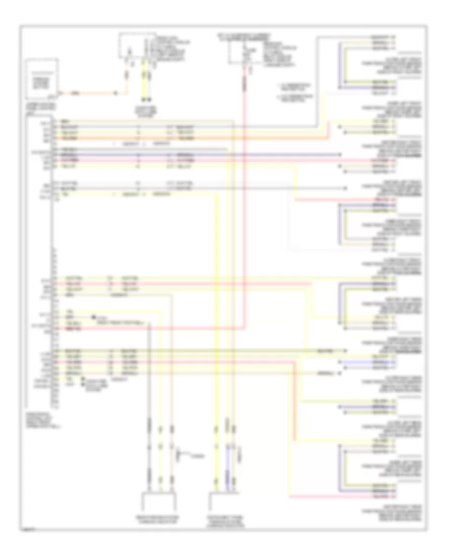 https://portal-diagnostov.com/license.html
Automotive Electricians Portal FZCO
Automotive Electricians Portal FZCO
https://portal-diagnostov.com/license.html
https://portal-diagnostov.com/license.html
Automotive Electricians Portal FZCO
Automotive Electricians Portal FZCOList of elements for Parktronic Wiring Diagram for Mercedes-Benz E250 Bluetec 4Matic 2014:
- (+) sh
- (+) sv
- (-) sh
- (-) sv
- 17c
- 30g
- C14i
- C22i
- Can e1 h
- Can e1 l
- Can e2 h
- Can e2 l
- Center left front parktronic distance sensor (behind center left side of front bumper)
- Center left rear parktronic distance sensor (behind center left side of rear bumper)
- Center right front parktronic distance sensor (behind center right
- Center right rear parktronic distance sensor (behind center right side of rear bumper)
- Computer data lines system
- Front sam control module w/ fuse & relay module (left rear of engine compt)
- Fuse 5a
- Hot w/ quiescent current cutout relay energized
- Inner left front parktronic distance sensor (behind inner left side of front bumper)
- Inner left rear parktronic distance sensor (behind inner left side of rear bumper)
- Inner right front parktronic distance sensor (behind inner right side of front bumper)
- Inner right rear parktronic distance sensor (behind inner right side of rear bumper)
- Instrument panel parking system warning indicator
- Lin 1
- Outer left front parktronic distance sensor (behind outer left side of front bumper)
- Outer left rear parktronic distance sensor (behind outer left side of rear bumper)
- Outer right front parktronic distance sensor (behind outer right side of front bumper)
- Outer right rear parktronic distance sensor (behind outer right side of rear bumper)
- Parking system button
- Parktronic control unit (right front upper footwell)
- Protection
- Rear parking system warning indicator
- Rear sam control module w/ fuse & relay module (right side of luggage compt)
- S10h
- S11h
- S12h
- S1v
- S2v
- S3v
- S4v
- S5v
- S6v
- S7h
- S8h
- S9h
- Side of front bumper)
- Upper control panel control unit
- W/ pedestrian protection
- W/o pedestrian
- W15/1 (right front footwell)
- Wagon
- Wh (+)
- Wh (-)
- Wh (data)
- Wv (+)
- Wv (-)
- Wv (data)
- X18/2-c1
- X26/38-c1
- X26/38-c2
- X35/27-c1
- X35/28-c1
Rear Camera Wiring Diagram for Mercedes-Benz E250 Bluetec 4Matic 2014
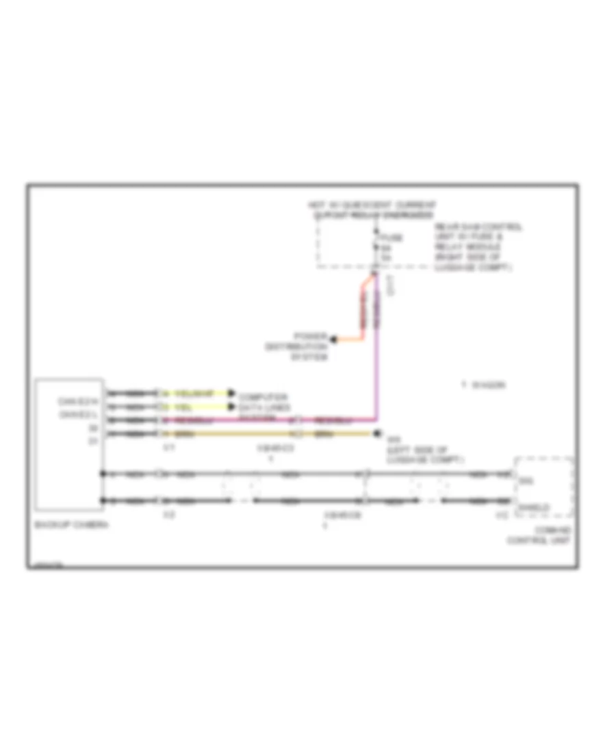 https://portal-diagnostov.com/license.html
Automotive Electricians Portal FZCO
Automotive Electricians Portal FZCO
https://portal-diagnostov.com/license.html
https://portal-diagnostov.com/license.html
Automotive Electricians Portal FZCO
Automotive Electricians Portal FZCOList of elements for Rear Camera Wiring Diagram for Mercedes-Benz E250 Bluetec 4Matic 2014:
- Backup camera
- C11t
- Can e2 h
- Can e2 l
- Comand control unit
- Computer data lines system
- Fuse 5a
- Hot w/ quiescent current cutout relay energized
- Nca
- Power distribution system
- Rear sam control unit w/ fuse & relay module (right side of luggage compt)
- Shield
- Sig
- W6 (left side of luggage compt)
- Wagon
- X8/45-c3
- X8/45-c8
Stereo Multifunction Camera Wiring Diagram for Mercedes-Benz E250 Bluetec 4Matic 2014
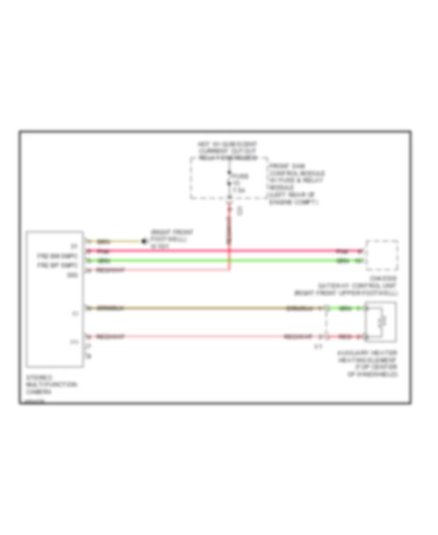 https://portal-diagnostov.com/license.html
Automotive Electricians Portal FZCO
Automotive Electricians Portal FZCO
https://portal-diagnostov.com/license.html
https://portal-diagnostov.com/license.html
Automotive Electricians Portal FZCO
Automotive Electricians Portal FZCOList of elements for Stereo Multifunction Camera Wiring Diagram for Mercedes-Benz E250 Bluetec 4Matic 2014:
- (+)
- (-)
- (right front footwell) w15/1
- 30g
- Auxiliary heater heating element (top center of windshield)
- C2i
- Chassis gateway control unit (right front upper footwell)
- Fr2 bm smpc
- Fr2 bp smpc
- Front sam control module w/ fuse & relay module (left rear of engine compt)
- Fuse 7.5a
- Hot w/ quiescent current cutout relay energized
- Pnk
- Red
- Stereo multi-function camera
POWER DISTRIBUTION
Power Distribution Wiring Diagram (1 of 5) for Mercedes-Benz E250 Bluetec 4Matic 2014
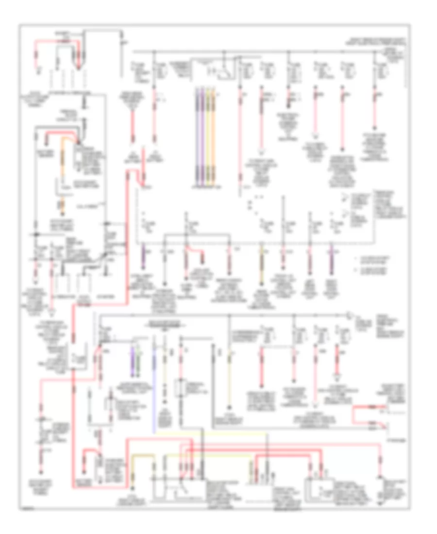 https://portal-diagnostov.com/license.html
Automotive Electricians Portal FZCO
Automotive Electricians Portal FZCO
https://portal-diagnostov.com/license.html
https://portal-diagnostov.com/license.html
Automotive Electricians Portal FZCO
Automotive Electricians Portal FZCOList of elements for Power Distribution Wiring Diagram (1 of 5) for Mercedes-Benz E250 Bluetec 4Matic 2014:
- (diagram 1 of 5)
- (or red)
- (right rear of engine compt) front electrical prefuse box
- 150a
- 20a
- 3.5l hybrid
- A/c housing (w/ 2-zone thermatic & 3-zone thermotronic)
- Additional battery relay circuit 30 fuse additional fuse (spare wheelwell, behind battery)
- Airmatic relay (if equipped & w/ electronic level control w/ hydraulics)
- Alarm siren (if equipped)
- Alternator
- B1s
- Battery sensor
- C12i
- C18m
- C19i
- C1a
- C1v
- C2v
- C3i
- C8d
- C9i
- Combustion engine & air conditioning w/ integrated control fan motor (w/ fan motor 800w & 650w)
- Coolant circulation pump relay (4.6l turbo)
- Eco start/ stop function additional battery
- Eco start/ stop function circuit 30 cable connector
- Eco start/stop function additional battery relay (under right side of luggage compt floor)
- Eco start/stop function diode
- Electrical power steering control unit (if equipped)
- Except 3.5l hybrid
- From fuse 157 a
- From rear prefuse box (diagram 1 of 5)
- Front electrical prefuse box (right rear of engine compt)
- Front sam control unit w/ fuse & relay module (left rear of engine compt)
- Fuse 100a
- Fuse 150a
- Fuse 150a (or 100a)
- Fuse 150a 350a
- Fuse 15a
- Fuse 20a
- Fuse 30a
- Fuse 400a
- Fuse 400a (except 3.5l hybrid)
- Fuse 40a
- Fuse 50a
- Fuse 50a 80a
- Fuse 60a
- Fuse 7.5a
- Glow output stage
- Glow output stage (3.0l turbo diesel)
- Ig1
- Im1
- Intelligent servo module for direct select (if equipped)
- Interference suppression capacitor
- Interior fuse box (except 3.5l hybrid)
- Interior protection & tow-away protection control unit (if equipped)
- Ism
- Left rear door control unit
- M10
- Mr1
- Mr4 red
- Mr5 red
- Mr6
- Mr7
- Mr8
- Mrg2
- On-board electrical system battery (w/ front battery)
- Ptc heater booster (if equipped, w/ 2-zone thermatic & 3-zone thermotronic)
- Pyrofuse
- Quiescent current cutout relay
- Rear blower motor (w/ 3-zone thermotronic)
- Rear on-board electrical system battery (w/ rear battery)
- Rear prefuse box (right front of luggage compt floor)
- Rear sam control module w/ fuse/ relay module (right side of luggage compt)
- Rear sam control unit w/ fuse & relay module circuit 30 fuse
- Rear window antenna amplifier 1, fm 1, am, cl (zv) & keyless go antenna amplifier
- Red
- Red mr3
- Red mr9
- Right front door control unit
- Starter
- Stationary heater fuse
- Stationary heater unit (3.5l hybrid)
- Stationary heater unit (except hybrid)
- Terminal block (circuit 30)
- To circuit 15 relay (diagram 2 of 5)
- To front sam control module w/ fuse/ relay module (diagram 4 of 5)
- To front sam control module w/ fuse/ relay module (diagram 5 of 5)
- To front sam control module w/ fuse/relay module (diagram 5 of 5)
- To fuse 155 (diagram 1 of 5)
- To fuse 42 (diagram 2 of 5)
- To hybrid fuse & relay module (diagram 4 of 5)
- To rear sam control module w/ fuse/ relay module (diagram 1 of 5)
- Trunk lid control unit (sedan) tailgate control unit (wagon)
- W/ eco start/ stop system
- W/ front battery
- W/ rear battery
- W/o eco start/ stop system
- W16/4 (right rear of engine compt)
- W2 (right side of engine compt)
- W7/8 (right side of luggage compt)
Power Distribution Wiring Diagram (2 of 5) for Mercedes-Benz E250 Bluetec 4Matic 2014
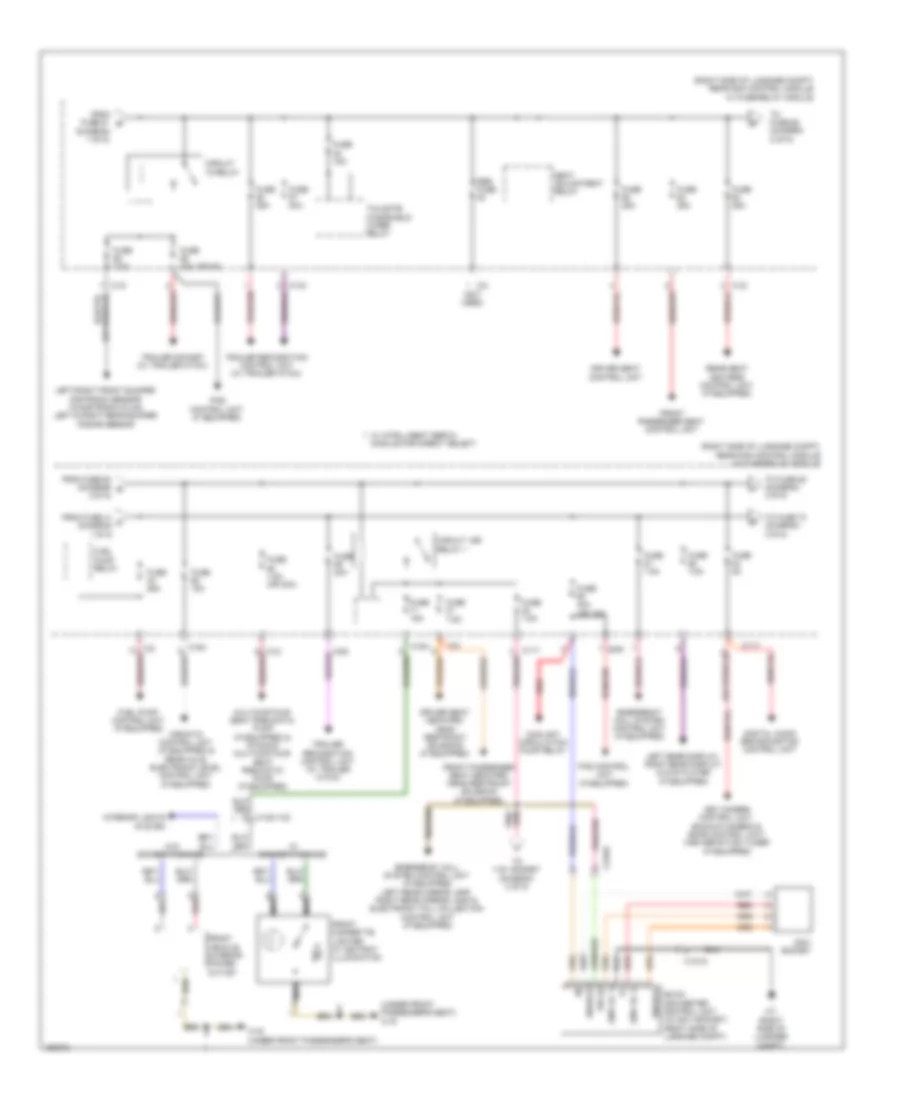 https://portal-diagnostov.com/license.html
Automotive Electricians Portal FZCO
Automotive Electricians Portal FZCO
https://portal-diagnostov.com/license.html
https://portal-diagnostov.com/license.html
Automotive Electricians Portal FZCO
Automotive Electricians Portal FZCOList of elements for Power Distribution Wiring Diagram (2 of 5) for Mercedes-Benz E250 Bluetec 4Matic 2014:
- (diagram 1 of 5)
- (not used)
- (or 5a)
- (right side of luggage compt) rear sam control module w/ fuse/relay module
- (under front passenger's seat) w19
- 15r (1)
- 230v ac 1
- 230v ac 2
- 230v socket
- 360° camera control unit, backup camera & sdar control unit/ high definition tuner (if equipped)
- Aag
- Airmatic control unit (if equipped) & rear axle electronic level control unit (if equipped)
- C11t
- C12i
- C13a
- C15h
- C3i
- Circuit 15 relay
- Circuit 15r relay 1
- Coolant circulation pump relay
- Dc/ac converter control unit (w/ 230v socket) (right side of luggage compt)
- Digital audio broadcasting control unit
- Driver seat control unit
- Driver seat neck-pro head restraint solenoid (if equipped)
- Emergency call system control unit (if equipped)
- Emergency call system control unit (if equipped) left rear mirror lamp, right rear mirror lamp & electronic toll collection control unit (if equipped)
- Enable
- From fuse 41 c (diagram 1 0f 5)
- From fuse 61 b
- From fuse 63 (diagram g 2 0f 5)
- Front cigarette lighter w/ ashtray illumination
- Front passenger seat control unit
- Front passenger seat neck-pro head restraint solenoid (if equipped)
- Front vehicle interior power outlet
- Fuel pump control unit (if equipped)
- Fuel pump relay
- Fuse 15a
- Fuse 20a
- Fuse 25a
- Fuse 30a
- Fuse 40a (or 15a)
- Fuse 5a
- Fuse 7.5a
- Fuse 7.5a (or 30a)
- Interior lights system
- Left rear display, right rear display & dvd player (if equipped)
- Left/right front bumper distronic sensor (w/distronic plus) left & right rear bumper radar sensor
- Module for direct select
- Multicontour seat pneumatic pump (if equipped) & dynamic multicontour seat pneumatic pump (if equipped)
- Nca
- Pas control unit (if equipped)
- Rear seat heaters control unit (if equipped)
- Red
- Res fuse
- Scr
- Seat adjustment relay
- Tailgate windshield wiper relay
- To 115v socket (diagram 3 of 5)
- To fuse 68 (diagram 2 of 5)
- To fuse 73 (diagram 3 0f 5)
- To fuse 85 (diagram 3 0f 5)
- Trailer recognition control unit (w/ trailer hitch)
- Trailer socket (w/ trailer hitch)
- W/ intelligent servo
- W/ smoker package
- W/o smoker package
- W19 (under front passenger's seat)
- W7 (right side of luggage compt)
- X137/8
Power Distribution Wiring Diagram (3 of 5) for Mercedes-Benz E250 Bluetec 4Matic 2014
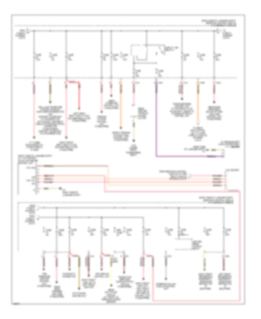 https://portal-diagnostov.com/license.html
Automotive Electricians Portal FZCO
Automotive Electricians Portal FZCO
https://portal-diagnostov.com/license.html
https://portal-diagnostov.com/license.html
Automotive Electricians Portal FZCO
Automotive Electricians Portal FZCOList of elements for Power Distribution Wiring Diagram (3 of 5) for Mercedes-Benz E250 Bluetec 4Matic 2014:
- (not used)
- (right side of luggage compt) (w/ 115v socket) dc/ac converter control unit
- (right side of luggage compt) rear sam control module w/ fuse/relay module
- (right side of luggage compt) w7
- (w/ rear socket) load compartment socket
- 115v ac1
- 115v ac2
- 115v socket
- 30g
- C10r
- C11t
- C12i
- C14i
- C15h
- C2g
- C3i
- Cellular telephone system antenna amplifier/compensator unit (comfort telephony w/ compensator stationary heater) & mobile phone electrical connector (if equipped & comfort telephony w/o compensator)
- Circuit 15r relay 2
- Diagnostic connector
- From fuse 67 j (diagram 3 0f 5)
- From fuse 84 (diagram 2 of 5)
- From fuse 87 (diagram 2 0f 5)
- From rear sam control module w/ fuse relay module v (diagram 2 of 5)
- Fuse 10a
- Fuse 15a
- Fuse 20a
- Fuse 25a
- Fuse 40a
- Fuse 50a
- Fuse 5a
- Fuse 7.5a
- Heated rear window relay
- Keyless go control unit
- Left front reversible emergency tensioning retractor (if equipped)
- Left front seat ventilation blower regulator (if equipped)
- Media interface control unit (if equipped)
- Parking system control unit (if equipped)
- Radar sensors control unit (w/ distronic plus, blind spot assist) & chassis gateway control unit
- Rear bass speaker & sound system amplifier control unit (if equipped)
- Rear bass speaker amplifier (if equipped)
- Rear center console power outlet
- Rear switching module (w/ trunk lid opening/closing sensor)
- Red
- Res fuse
- Right front lamp unit & left front lamp unit
- Right front lamp unit, left front lamp unit & keyless go control unit (if equipped)
- Right front reversible emergency tensioning retractor (if equipped)
- Right front seat ventilation blower regulator (if equipped)
- Stationary heater unit
- Steering column module control unit
- Telematics services communication module (if equipped)
- Tire pressure monitor control unit (if equipped)
- To front sam control unit w/ fuse & relay module (diagram 4 of 5)
- To fuse 70 (diagram 3 of 5)
- Tv tuner (analog/digital) (if equipped & w/ ece)
- W19 (under front passenger's seat)
- W7 (right side of luggage compt)
- Weight sensing system (wss) control unit (if equipped)
Power Distribution Wiring Diagram (4 of 5) for Mercedes-Benz E250 Bluetec 4Matic 2014
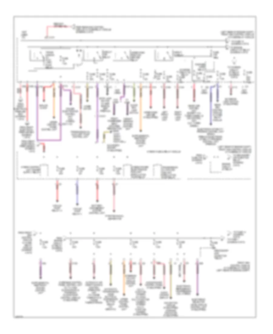 https://portal-diagnostov.com/license.html
Automotive Electricians Portal FZCO
Automotive Electricians Portal FZCO
https://portal-diagnostov.com/license.html
https://portal-diagnostov.com/license.html
Automotive Electricians Portal FZCO
Automotive Electricians Portal FZCOList of elements for Power Distribution Wiring Diagram (4 of 5) for Mercedes-Benz E250 Bluetec 4Matic 2014:
- (diagram 4 0f 5)
- (left rear of engine compt) front sam control module w/ fuse/relay module
- (not used)
- Analog clock
- Audio/ comand display
- Audio/comand control panel (if equipped)
- Automatic air conditioning & control operating unit (w/ 2-zone thermatic & 3-zone thermotronic)
- Automatic transmission mode button & suspension button group (w/ airmatic)
- Battery management system control unit
- C10t
- C11c
- C13d
- C14m
- C15m
- C16s red
- C1m
- C2i
- C5c
- C6i
- C7i
- C8s
- C9g
- Circuit 15 relay
- Circuit 15r relay
- Electronic refrigerant compressor (3.5l hybrid)
- Electronic selector level module control unit (if equipped)
- Electronic stability program control unit (basic) premium electronic stability program control unit (premium)
- Engine circuit 87 relay
- Exterior light switch (if equipped)
- Fanfare horn relay
- From front electrical prefuse box (diagram 1 of 5)
- From front electrical w prefuse box (diagram 1 0f 5)
- From front sam control module w/ fuse/ relay module (diagram 4 of 5)
- From fuse 31b n
- From o engine circuit 87 relay (diagram 4 0f 5)
- From rear sam control module w/ fuse/relay module (diagram 3 0f 5)
- Front passenger seat occupied recognition & ascr
- Front sam control module w/ fuse/relay module (left rear of engine compt)
- Fuse 10a
- Fuse 15a
- Fuse 20a
- Fuse 20a (or 7.5a)
- Fuse 30a
- Fuse 31a 15a
- Fuse 31b 15a
- Fuse 40a
- Fuse 5a
- Fuse 7.5a
- Glove box lamp switch
- Glove box socket (if equipped)
- Hybrid fuse & relay module
- Hybrid power electronics coolant circulation pump relay
- Left front lamp unit
- Me-sfi (me) control unit (except 3.0l turbo diesel) & cdi control unit (3.0l turbo diesel)
- Multi- function camera (w/ mono multi-function camera) stereo multi- function camera (if equipped)
- Navigation module (if equipped) command fan motor (if equipped)
- Overhead control panel control unit (w/ tilting/ sliding roof) & panoramic sliding roof control module (if equipped)
- Pnk/red
- Power electronics control unit (3.5l hybrid)
- Pyrotechnical separator
- Rear sam control module w/ fuse/ relay module
- Red
- Right front lamp unit
- Secondary air injection relay
- Starter circuit 50 relay
- Steering column module control unit
- Stop lamp switch (w/ esp basic & esp premium)
- To chassis circuit 87 relay (diagram 5 0f 5)
- To engine circuit 87 relay (diagram 4 0f 5)
- To fuse 1 (diagram 5 0f 5)
- To fuse 14 (diagram 5 0f 5)
- To fuse 15 (diagram 4 0f 5)
- To secondary air injection relay (diagram 4 0f 5)
- Trans- mission oil auxi- liary pump relay
- Transmission oil auxiliary pump control unit
- Transmission oil cooling coolant circulation pump relay
- Upper control panel control unit
- Vacuum pump relay (+)
- Vacuum pump relay (-)
- W/o wss
- W15/7 (right front footwell)
- Weight sensing system control unit
- Wiper motor
- Wiper park heater (if equipped)
- Wiper park position heater relay
- X18-c1
- X83/11-c2
Power Distribution Wiring Diagram (5 of 5) for Mercedes-Benz E250 Bluetec 4Matic 2014
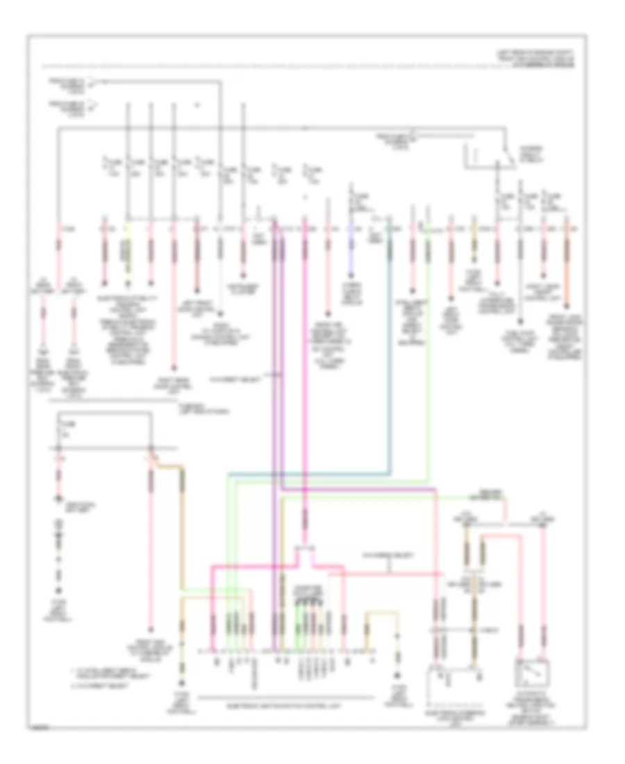 https://portal-diagnostov.com/license.html
Automotive Electricians Portal FZCO
Automotive Electricians Portal FZCO
https://portal-diagnostov.com/license.html
https://portal-diagnostov.com/license.html
Automotive Electricians Portal FZCO
Automotive Electricians Portal FZCOList of elements for Power Distribution Wiring Diagram (5 of 5) for Mercedes-Benz E250 Bluetec 4Matic 2014:
- (left rear of engine compt) front sam control module w/ fuse/relay module
- (not used)
- 30z
- Additional battery
- Automatic transmission neutral position switch (base of shift lever assembly)
- C10t
- C11c
- C12s
- C15m
- C17c
- C19i
- C2i
- C4i
- C5c
- C7i
- C9g
- Can-b h
- Can-b l
- Can-e1 h
- Can-e1 l
- Cdi control unit (3.0l turbo diesel)
- Chassis circuit 87 relay
- Computer data lines system
- Data
- Electronic ignition switch control unit
- Electronic stability program control unit (basic), premium electronic stability program control unit (premium) & regenerative braking system control unit (if equipped)
- Electronic steering lock control unit
- Ezs backup
- From front electrical prefuse box (diagram 1 of 5)
- From fuse 16 (diagram 4 of 5)
- From fuse 32 (diagram 4 of 5)
- From fuse 5 u (diagram 4 of 5)
- From rear prefuse box (diagram 1 of 5)
- Front long range radar sensor & collision prevention assist controller (if equipped)
- Front sam control module w/ fuse/relay module
- Fuel pump control unit (3.0l turbo diesel)
- Fully integrated transmission control unit
- Fuse 10a
- Fuse 20a
- Fuse 25a
- Fuse 30a
- Fuse 40a
- Fuse 5a
- Fuse 7.5a
- Fuse box (left end of dash)
- Hybrid fuse & relay module
- Instrument cluster
- Intelligent servo module for direct select (if equipped)
- Left front door control unit
- Me-sfi (me) control unit (except 3.0l turbo diesel) &
- Module for direct select
- Night vision assist control unit
- P not
- Radio (w/ audio 20) & comand control unit (if equipped)
- Red
- Right rear door control unit
- W/ front battery
- W/ intelligent servo
- W/ keyless go
- W/ rear battery
- W/o direct select
- W/o keyless go
- W15/5 (left front footwell)
- X190-c1
POWER DOOR LOCKS
Automatic Door Locks Wiring Diagram (1 of 2) for Mercedes-Benz E250 Bluetec 4Matic 2014
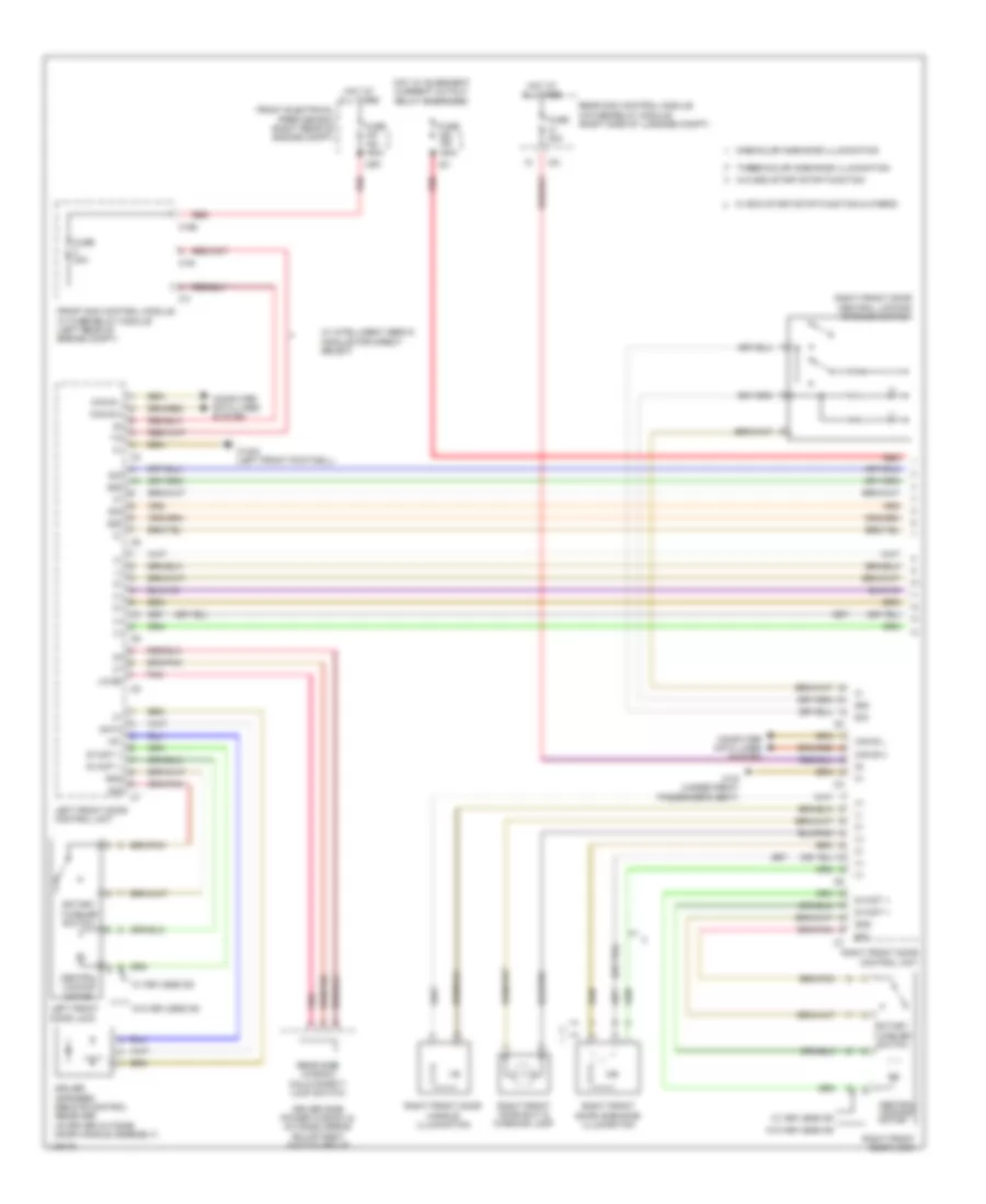 https://portal-diagnostov.com/license.html
Automotive Electricians Portal FZCO
Automotive Electricians Portal FZCO
https://portal-diagnostov.com/license.html
https://portal-diagnostov.com/license.html
Automotive Electricians Portal FZCO
Automotive Electricians Portal FZCOList of elements for Automatic Door Locks Wiring Diagram (1 of 2) for Mercedes-Benz E250 Bluetec 4Matic 2014:
- (+)
- (-)
- +5v
- 150a
- 58d
- C165
- C19i
- C3i
- C7i
- Can b h
- Can b l
- Central locking motor
- Computer data lines system
- Data
- Driver infrared remote control receiver (in driver outside door handle assembly)
- Driver side power window & outside mirror adjustment switch group
- Front electrical prefuse box (right rear of engine compt)
- Front sam control module w/ fuse/relay module (left rear of engine compt)
- Fuse
- Fuse 150a
- Fuse 30a
- Gnd
- Hot at all times
- Hot w/ quiescent current cutout relay energized
- Ig1
- Left front door control unit
- Left front door lock
- Lin b5
- Mr7
- One-color ambiance illumination
- Pnk
- Rear sam control module w/fuse/relay module (right side of luggage compt)
- Rear side window child safety lock switch
- Red
- Right front door ambiance illumination
- Right front door central locking interior switch
- Right front door control unit
- Right front door exit & warning lamp
- Right front door handle illumination
- Right front door lock
- Rotary tumbler switch
- Sig
- Three-color ambiance illumination
- W/ eco start/stop function & hybrid
- W/ intelligent servo module for direct select
- W/ keyless go
- W/o eco start/stop function
- W/o keyless go
- W15/2 (left front footwell)
- W19 (under front passenger's seat)
- Zv-mot +
Automatic Door Locks Wiring Diagram (2 of 2) for Mercedes-Benz E250 Bluetec 4Matic 2014
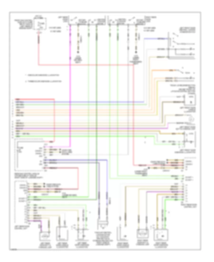 https://portal-diagnostov.com/license.html
Automotive Electricians Portal FZCO
Automotive Electricians Portal FZCO
https://portal-diagnostov.com/license.html
https://portal-diagnostov.com/license.html
Automotive Electricians Portal FZCO
Automotive Electricians Portal FZCOList of elements for Automatic Door Locks Wiring Diagram (2 of 2) for Mercedes-Benz E250 Bluetec 4Matic 2014:
- (+)
- (-)
- 30g
- C1v
- C3i
- C5h
- C7i
- C9i
- Can b h
- Can b l
- Can-b h
- Can-b l
- Central locking motor
- Computer data lines system
- Front sam control module w/ fuse/ relay module (left rear of engine compt)
- Fuse 30a
- Hot at all times
- Left front door ambiance illumination
- Left front door central locking interior switch
- Left front door exit & warning lamp
- Left front door handle illumination
- Left rear door ambiance illumination
- Left rear door control unit
- Left rear door exit & warning lamp
- Left rear door handle illumination
- Left rear door lock
- One-color ambiance illumination
- Rear sam control module w/fuse & relay module (right side of luggage compt)
- Red
- Right rear door ambiance illumination
- Right rear door control unit
- Right rear door exit & warning lamp
- Right rear door handle illumination
- Right rear door lock
- Rotary tumbler switch
- Sig
- Tank cap central locking motor (w/ two-away protection & interior protection) (right side of luggage compt)
- Three-color ambiance illumination
- Trunk lid release button (sedan) driver trunk lid/ liftgate control button (wagon)
- W/ keyless
- W/o keyless
- W18 (under driver's seat)
- W19 (under front passenger's seat)
- X35/3-c1
- X35/4-c1
- X8/46-c1
- Zv-mot +
Keyless Go System Wiring Diagram for Mercedes-Benz E250 Bluetec 4Matic 2014
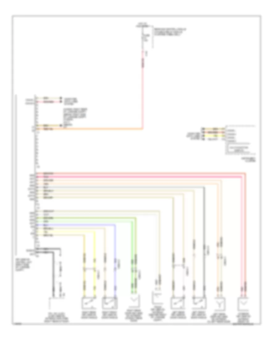 https://portal-diagnostov.com/license.html
Automotive Electricians Portal FZCO
Automotive Electricians Portal FZCO
https://portal-diagnostov.com/license.html
https://portal-diagnostov.com/license.html
Automotive Electricians Portal FZCO
Automotive Electricians Portal FZCOList of elements for Keyless Go System Wiring Diagram for Mercedes-Benz E250 Bluetec 4Matic 2014:
- (-)
- (wagon: right rear of luggage compt) (sedan: right side of luggage compt) (wagon) (w7/1) (sedan) w7
- Ant
- Ant c5
- C14i
- Can b h
- Can b l
- Can-b h
- Can-b l
- Can-e h
- Can-e l
- Computer data lines system
- Data
- Fm1, am, cl(zv) & keyless go antenna amplifier (right rear of roof)
- Fuse 15a
- Gnd
- Hot at all times
- Instrument cluster
- Interior keyless go antenna (front of center console)
- Keyless go control unit (right side of luggage compt)
- Left front keyless go door handle
- Left rear door keyless go antenna (in left rear door)
- Left rear keyless go door handle
- Multi-function display
- Nca
- Pnk
- Rear sam control module w/fuse & relay module (in spare wheelwell)
- Right front keyless go door handle
- Right rear door keyless go antenna (in right rear door)
- Right rear keyless go door handle
- Shield
- Sig
- Trunk keyless go antenna (center front of luggage compt)
- X35/1-c3
- X35/2-c3
- X35/3-c1
- X35/4-c1
POWER MIRRORS
Automatic Day/Night Mirror Wiring Diagram for Mercedes-Benz E250 Bluetec 4Matic 2014
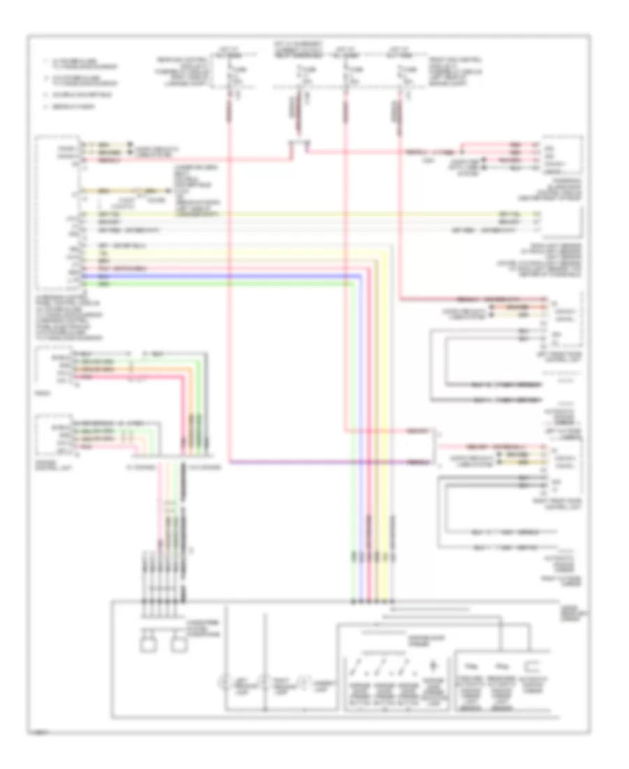 https://portal-diagnostov.com/license.html
Automotive Electricians Portal FZCO
Automotive Electricians Portal FZCO
https://portal-diagnostov.com/license.html
https://portal-diagnostov.com/license.html
Automotive Electricians Portal FZCO
Automotive Electricians Portal FZCOList of elements for Automatic Day/Night Mirror Wiring Diagram for Mercedes-Benz E250 Bluetec 4Matic 2014:
- (under driver's seat) (coupe & convertible) w18/3 w6 (sedan & wagon) (left side of luggage compt)
- 15r
- 30g
- 58d
- Ambient lamp
- Automatic dimming mirror
- C13d
- C3i
- C7i
- Can b h
- Can b l
- Can-b h
- Can-b l
- Comand control unit
- Computer data lines system
- Coupe
- Coupe & convertible
- Forward automatic dimming mirror light sensor
- Front sam control module w/ fuse/relay module (left rear of engine compt)
- Fuse 30a
- Garage door opener
- Garage door opener button
- Garage door opener indicator lamp
- Gnd
- Hands-free system microphone
- Hot at all times
- Hot w/ quiescent current cutout relay energized
- Inside rearview mirror
- Left front door control unit
- Left outside mirror
- Left reading lamp
- Lin 2
- Ll l
- Ll r
- Mic 1
- Mic 2
- Nca
- Overhead control panel control module (w/ power glass tilting/sliding sunroof) overhead control panel electronics (w/o power glass tilting/sliding sunroof)
- Panoramic sliding roof control module (center front of roof)
- Pnk
- Radio
- Rain/light sensor (w/ rain/light sensor) light sensor (coupe: w/o rain/light sensor) (w/ rain/light sensor: top center of windshield)
- Rear sam control module w/ fuse/relay module (right side of luggage compt)
- Rearward automatic dimming mirror light sensor
- Red
- Right front door control unit
- Right outside mirror
- Right reading lamp
- Sedan & wagon
- Shield
- Sig
- Tilting/sliding sunroof
- W/ comand
- W/ power glass tilting/sliding sunroof
- W/o comand
- W/o power glass
- X18/37 x18/37-c1
- X204
Fold-back Mirrors Wiring Diagram for Mercedes-Benz E250 Bluetec 4Matic 2014
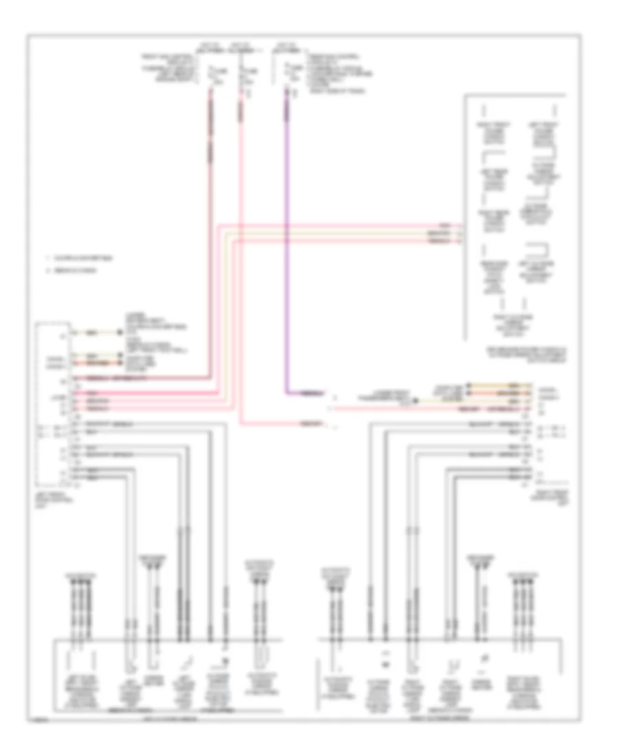 https://portal-diagnostov.com/license.html
Automotive Electricians Portal FZCO
Automotive Electricians Portal FZCO
https://portal-diagnostov.com/license.html
https://portal-diagnostov.com/license.html
Automotive Electricians Portal FZCO
Automotive Electricians Portal FZCOList of elements for Fold-back Mirrors Wiring Diagram for Mercedes-Benz E250 Bluetec 4Matic 2014:
- (+)
- (or red)
- (under driver's seat) (coupe & convertible) w18
- (under front passenger's seat) w19
- Automatic day/night mirror circuit
- Automatic dimming mirror (if equipped)
- C3i
- C7i
- Can-b h
- Can-b l
- Computer data lines system
- Coupe & convertible
- Defogger system
- Driver-side power window & outside mirror adjustment switch group
- Front sam control module w/ fuse/relay module (left rear of engine compt)
- Fuse 30a
- Hot at all times
- Left blind- spot assist readiness & warning indicator (if equipped)
- Left front door control unit
- Left front power window switch
- Left outside mirror
- Left outside mirror adjustment switch
- Left outside mirror ambient lamp (sedan & wagon)
- Left outside mirror turn signal lamp
- Left rear power window switch
- Lin b5
- Mirror heater
- Navigation system
- Nca
- Outside mirror adjustment switch
- Outside mirror fold in/ fold out electric motor
- Outside mirror fold in/ fold out electric motor (if equipped)
- Outside mirror fold in/fold out switch
- Pnk
- Rear sam control module w/ fuse/relay module (convertible: in spare wheelwell) (coupe: right side of trunk)
- Rear side window child safety lock switch
- Right blind- spot assist readiness & warning indicator (if equipped)
- Right front door control unit
- Right front power window switch
- Right outside mirror
- Right outside mirror adjustment switch
- Right outside mirror ambient lamp (sedan & wagon)
- Right outside mirror turn signal lamp
- Right rear power window switch
- Sedan & wagon
- W15/2 (sedan & wagon) (left front footwell)
POWER SEATS
Front Ventilation & Heated Seat Wiring Diagram for Mercedes-Benz E250 Bluetec 4Matic 2014
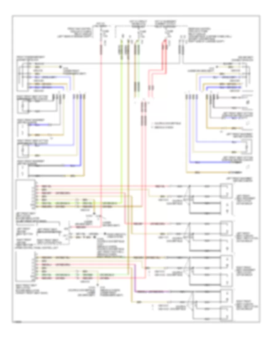 https://portal-diagnostov.com/license.html
Automotive Electricians Portal FZCO
Automotive Electricians Portal FZCO
https://portal-diagnostov.com/license.html
https://portal-diagnostov.com/license.html
Automotive Electricians Portal FZCO
Automotive Electricians Portal FZCOList of elements for Front Ventilation & Heated Seat Wiring Diagram for Mercedes-Benz E250 Bluetec 4Matic 2014:
- (+)
- (or nca)
- (or red)
- (under driver's seat)
- 30g
- C11c
- C11t
- C4i
- C7i
- C9i
- Computer data lines system
- Coupe & convertible
- Driver seat connector block
- Front passenger seat connector block
- Front sam control module w/ fuse & relay module (left rear of engine compt)
- Fuse 10a
- Fuse 7.5a
- Hot at all times
- Hot w/ circuit 15r relay(2) energized
- Hot w/ quiescent current cutout relay energized
- Left front backrest heated cushion
- Left front heated seat button
- Left front seat backrest ventilation motor group
- Left front seat cushion seat ventilation motor group
- Left front seat sitting surface heated cushion
- Left front seat ventilation blower regulator (in left front seat back)
- Left front seat ventilation button
- Lin 1
- Nca
- Rear sam control module w/ fuse/ relay module (convertible: in spare wheelwell) (except convertible: right side of luggage compt)
- Red
- Right front backrest heated cushion
- Right front heated seat button
- Right front seat backrest ventilation motor group
- Right front seat cushion seat ventilation motor group
- Right front seat sitting surface heated cushion
- Right front seat ventilation blower regulator (in right front seat back)
- Right front seat ventilation button
- Sedan & wagon
- Sig
- Upper control panel control unit
- W15/5 (coupe & convertible) w15/7 (sedan & wagon) (coupe & convertible: left front footwell) (sedan & wagon: right front footwell)
- W18
- W18 (under driver's seat)
- W18/3
- W18/3 (coupe & convertible) (under driver's seat)
- W19 (sedan & wagon) (under front passenger's seat)
- W19 (under front passenger's seat)
- X55/11-c1
- X55/12-c1
- X55/12-c2
- X55/13-c1
- X55/14-c1
- X55/14-c2
- X55/3-c4
- X55/3-c5
- X55/3-c51
- X55/3-c61
- X55/4-c4
- X55/4-c5
- X55/4-c51
- X55/4-c61
Rear Heated Seats Wiring Diagram for Mercedes-Benz E250 Bluetec 4Matic 2014
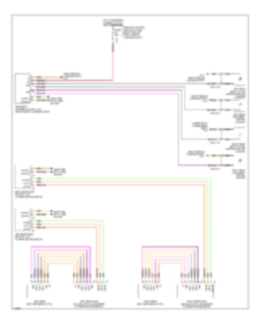 https://portal-diagnostov.com/license.html
Automotive Electricians Portal FZCO
Automotive Electricians Portal FZCO
https://portal-diagnostov.com/license.html
https://portal-diagnostov.com/license.html
Automotive Electricians Portal FZCO
Automotive Electricians Portal FZCOList of elements for Rear Heated Seats Wiring Diagram for Mercedes-Benz E250 Bluetec 4Matic 2014:
- (right rear of luggage compt) w7/1
- (under front passenger's seat) w19
- 58d
- C12i
- Can b h
- Can b l
- Can-b h
- Can-b l
- Computer data lines system
- Fuse 25a
- Hot w/ quiescent current cutout relay energized
- Led 1
- Led 2
- Led 3
- Left rear backrest heated cushion
- Left rear door analog/ digital converter (w/ rear heated seats)
- Left rear door control unit (w/ rear heated seats)
- Left rear seat heaters button
- Left rear seat sitting surface heated cushion
- Lin 30
- Lin 31
- Lin b10
- Lin b9
- Nca
- Rear sam control module w/ fuse/ relay module (right side of luggage compt)
- Rear seat heaters control unit (right side of luggage compt)
- Right rear backrest heated cushion
- Right rear door analog/ digital converter (w/ rear heated seats)
- Right rear door control unit (w/ rear heated seats)
- Right rear seat heaters button
- Right rear seat sitting surface heated cushion
- Sig
- W7/1 (right rear of luggage compt)
- X54/11-c1
- X54/11-c2
- X54/23-c1
- X54/24-c1
POWER TOP/SUNROOF
Power Top/Sunroof Wiring Diagram for Mercedes-Benz E250 Bluetec 4Matic 2014
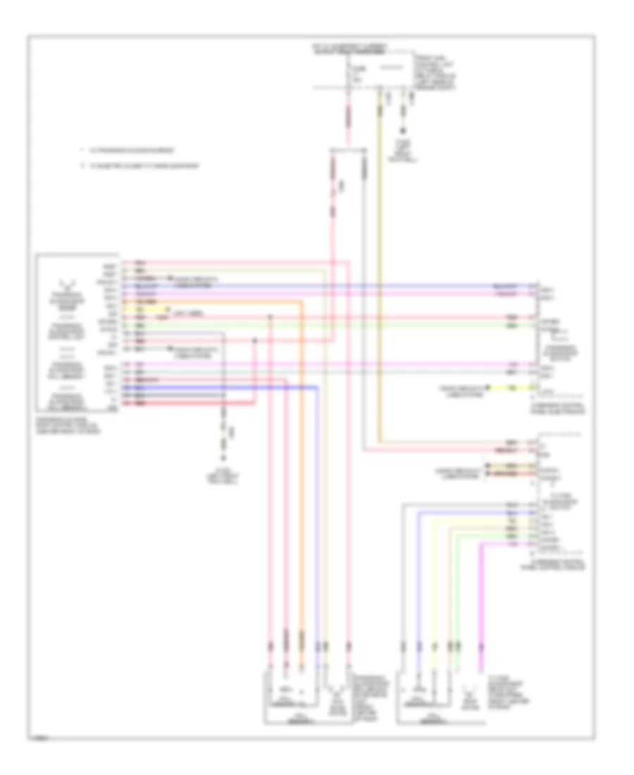 https://portal-diagnostov.com/license.html
Automotive Electricians Portal FZCO
Automotive Electricians Portal FZCO
https://portal-diagnostov.com/license.html
https://portal-diagnostov.com/license.html
Automotive Electricians Portal FZCO
Automotive Electricians Portal FZCOList of elements for Power Top/Sunroof Wiring Diagram for Mercedes-Benz E250 Bluetec 4Matic 2014:
- (not used)
- +12 v
- 30 rls
- 30g
- Anst
- C13d
- C15m
- Can b h
- Can b l
- Computer data lines system
- Front sam control unit w/ fuse & relay module (left rear of engine compt)
- Fuse 30a
- Hall sensor 1
- Hall sensor 2
- Hot w/ quiescent current cutout relay energized
- Hs (+)
- Hs 1
- Hs 2
- Hs gnd
- Lin 2
- Motor +
- Motor -
- Overhead control panel control module
- Overhead control panel electronics
- Panoramic sliding roof control module (center front of roof)
- Panoramic sliding roof control unit
- Panoramic sliding roof hall sensor 1
- Panoramic sliding roof hall sensor 2
- Panoramic sliding roof motor
- Panoramic sliding roof roller sun blind drive unit (front center of roof)
- Panoramic sliding roof switch
- Pnk
- Red
- Roof motor
- Sig
- Sig 1
- Sig 2
- Sig 3
- Sig 4
- Sun blind motor
- Tilting/ sliding roof drive unit (if equipped) (front center of roof)
- Tilting/ sliding roof switch
- W/ electric glass tilting/sliding roof
- W/ panoramic sliding sunroof
- W15/2 (left front footwell)
- W15/5 (left front footwell)
- X204
POWER WINDOWS
Power Windows Wiring Diagram (1 of 2) for Mercedes-Benz E250 Bluetec 4Matic 2014
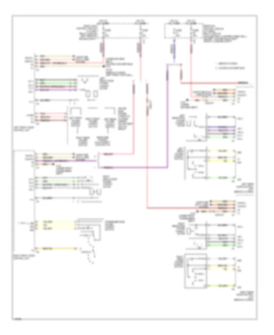 https://portal-diagnostov.com/license.html
Automotive Electricians Portal FZCO
Automotive Electricians Portal FZCO
https://portal-diagnostov.com/license.html
https://portal-diagnostov.com/license.html
Automotive Electricians Portal FZCO
Automotive Electricians Portal FZCOList of elements for Power Windows Wiring Diagram (1 of 2) for Mercedes-Benz E250 Bluetec 4Matic 2014:
- (under driver's seat) (coupe & convertible) w18
- 58d
- C3i
- C7i
- Can b h
- Can b l
- Computer data lines system
- Coupe & convertible
- Driver side power window & outside mirror adjustment switch group
- Fh h
- Fh t
- Front sam control module w/ fuse/ relay module (left rear of engine compt)
- Fuse 30a
- H (+)
- H (-)
- Hot at all times
- Hs (+)
- Hs (-)
- Hs 1
- Led
- Left front door control unit
- Left front door power window motor
- Left front power window switch
- Left rear door control unit (sedan & wagon)
- Left rear door power window motor
- Left rear power window switch
- Lin b5
- Passenger side power window switch
- Pnk
- Rear sam control module w/ fuse & relay module (convertible: in spare wheelwell) (except convertible: right side of luggage compt)
- Rear side window child safety lock switch
- Right front door control unit
- Right front door power window motor
- Right front power window switch
- Right rear door control unit (sedan & wagon)
- Right rear door power window motor
- Right rear power window switch
- Sedan & wagon
- Sig
- W15/2 (sedan & wagon) (left front footwell)
- W18 (under driver's seat)
- W19 (under front passenger's seat)
- X35/3-c1
- X35/4-c1
Power Windows Wiring Diagram (2 of 2) for Mercedes-Benz E250 Bluetec 4Matic 2014
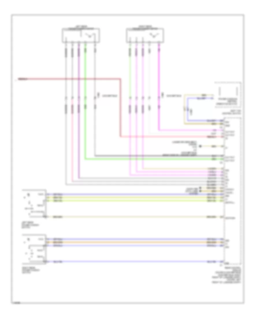 https://portal-diagnostov.com/license.html
Automotive Electricians Portal FZCO
Automotive Electricians Portal FZCO
https://portal-diagnostov.com/license.html
https://portal-diagnostov.com/license.html
Automotive Electricians Portal FZCO
Automotive Electricians Portal FZCOList of elements for Power Windows Wiring Diagram (2 of 2) for Mercedes-Benz E250 Bluetec 4Matic 2014:
- (under driver's seat) (coupe) w18
- 58d
- Can b h
- Can b l
- Computer data lines system
- Convertible
- Gnd
- Left rear power window motor
- Left rear power window switch
- Out put
- Power windows central operation switch
- Rear control module (coupe & convertible) (convertible: right front of luggage compt) (coupe: left front of luggage compt)
- Right rear power window motor
- Right rear power window switch
- Sig
- Sig pull
- Sig push
- Soft top control switch
- W7 (convertible) (right side of luggage compt)
- X138/1
- X16/2
- X16/3
Rear Window Sun Shade Wiring Diagram for Mercedes-Benz E250 Bluetec 4Matic 2014
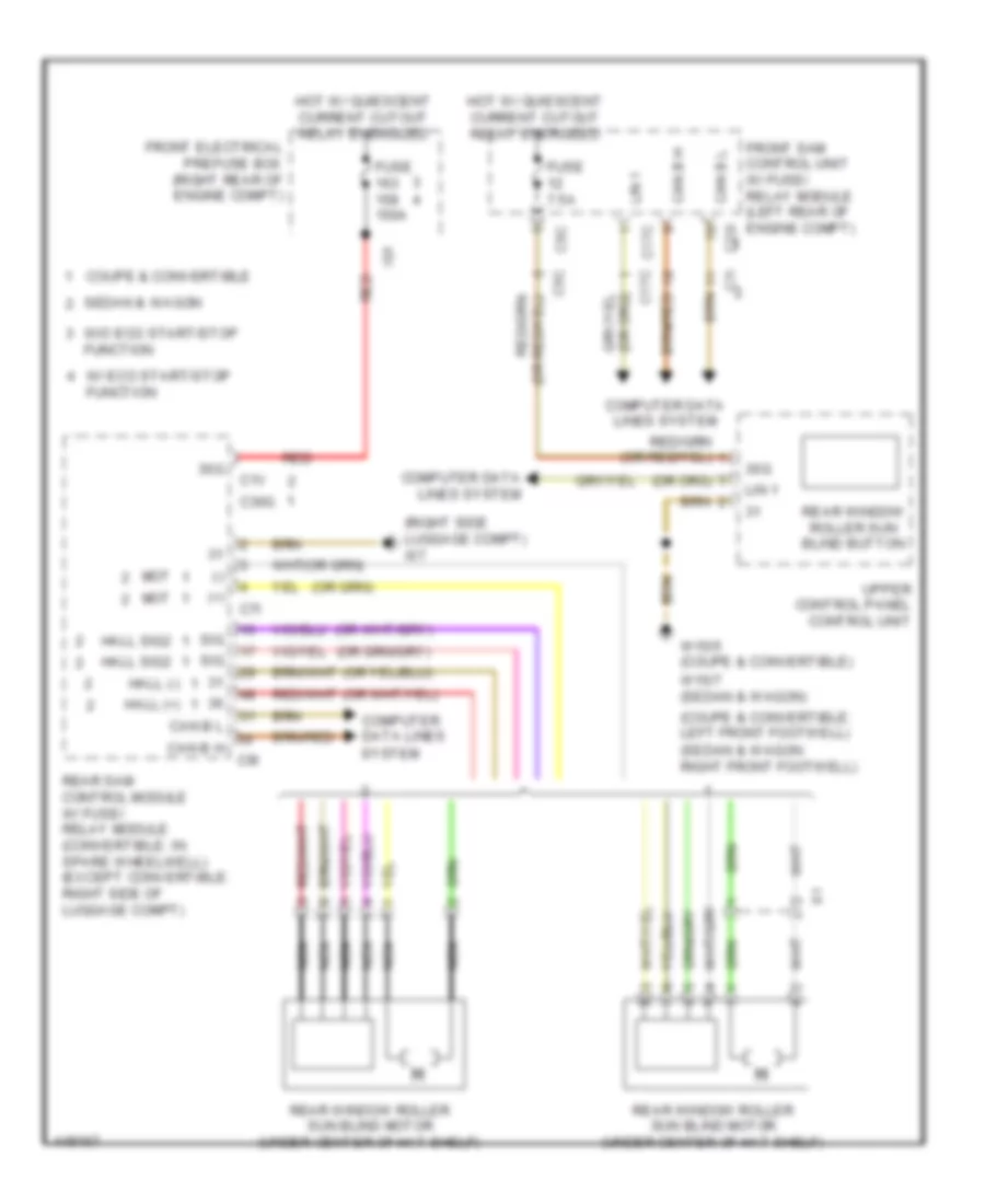 https://portal-diagnostov.com/license.html
Automotive Electricians Portal FZCO
Automotive Electricians Portal FZCO
https://portal-diagnostov.com/license.html
https://portal-diagnostov.com/license.html
Automotive Electricians Portal FZCO
Automotive Electricians Portal FZCOList of elements for Rear Window Sun Shade Wiring Diagram for Mercedes-Benz E250 Bluetec 4Matic 2014:
- (+)
- (-)
- (coupe & convertible: left front footwell)
- (right side luggage compt) w7
- (sedan & wagon: right front footwell)
- 30g
- C17c
- C1v
- C22i c7i
- C30g
- C5c
- C7i
- C9i
- Can b h
- Can b l
- Computer data lines
- Computer data lines system
- Coupe & convertible
- Front electrical prefuse box (right rear of engine compt)
- Front sam control unit w/ fuse/ relay module (left rear of engine compt)
- Fuse 150a
- Fuse 7.5a
- Hall (+)
- Hall (-)
- Hall sig2
- Hot w/ quiescent current cutout relay energized
- Ig1
- Lin 1
- Mot
- Nca
- Rear sam control module w/ fuse/ relay module (convertible: in spare wheelwell) (except convertible: right side of luggage compt)
- Rear window roller sun blind button
- Rear window roller sun blind motor (under center of hat shelf)
- Red
- Sedan & wagon
- Sig
- System
- Upper control panel control unit
- W/ eco start/stop function
- W/o eco start/stop function
- W15/5 (coupe & convertible)
- W15/7 (sedan & wagon)
RADIO
COMAND Actuation Wiring Diagram (1 of 3) for Mercedes-Benz E250 Bluetec 4Matic 2014
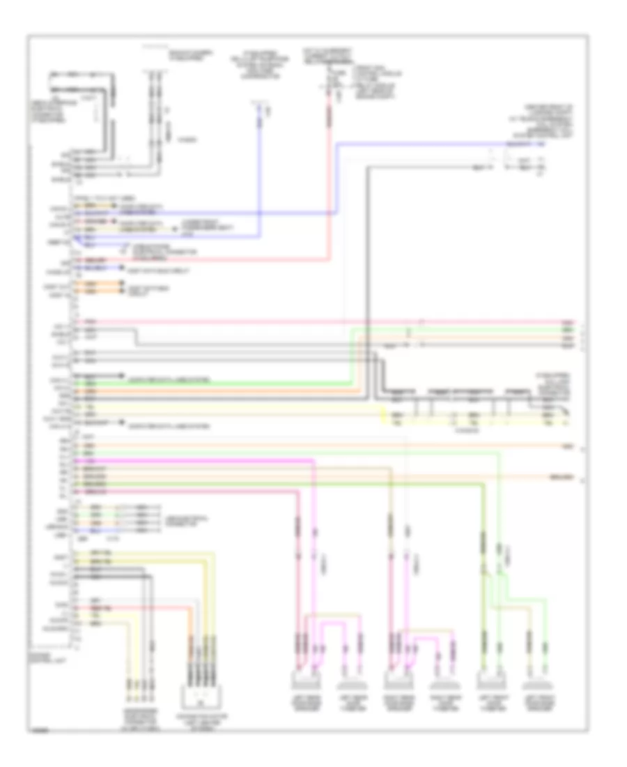 https://portal-diagnostov.com/license.html
Automotive Electricians Portal FZCO
Automotive Electricians Portal FZCO
https://portal-diagnostov.com/license.html
https://portal-diagnostov.com/license.html
Automotive Electricians Portal FZCO
Automotive Electricians Portal FZCOList of elements for COMAND Actuation Wiring Diagram (1 of 3) for Mercedes-Benz E250 Bluetec 4Matic 2014:
- (+)
- (-)
- (center front of luggage compt) (w/ teleaid emergency call system) emergency call system control unit
- (if equipped) aux jack electrical connector
- (if equipped) cellular telephone system antenna amplifier/ compensator
- (pins 1 to 8: not used)
- (under front passenger's seat) w19
- 30g
- Anst
- Aux1- gnd
- Aux1-l
- Aux1-r
- Aux1-s
- Aux2-gnd
- Aux2-l
- Aux2-r
- Aux2-s
- Backup camera (if equipped)
- C10t
- C2b
- Can a h
- Can a l
- Can b h
- Can b l
- Comand control unit
- Comand fan motor (left center of dash)
- Computer data lines system
- Diag
- Fl+
- Fl-
- Fr+
- Fr-
- Front sam control module w/ fuse/ relay module (left rear of engine compt)
- Fuse 20a
- Gnd
- Headphones electrical connector (w/ splitview)
- Hot w/ quiescent current cutout relay energized
- Keep on
- Left front door bass speaker
- Left front door tweeter
- Left rear door bass speaker
- Left rear door tweeter
- Media interface electrical connector (if equipped)
- Mic +
- Mic -
- Mic 1+
- Mic 2+
- Mobile phone electrical connector (if equipped)
- Most data bus circuit
- Most in
- Most out
- Mute
- Nca
- Pnk
- Right rear door bass speaker
- Right rear door tweeter
- Rl+
- Rl-
- Rr+
- Rr-
- Shield
- Sig
- Usb
- Usb bus
- Usb electrical connector
- Usb+
- Usb-
- Wagon
- Wake up
- X115
- X18/35-c2
- X18/71
- X35/1-c1
- X35/3-c1
- X35/4-c1
- X8/45-c8
COMAND Actuation Wiring Diagram (2 of 3) for Mercedes-Benz E250 Bluetec 4Matic 2014
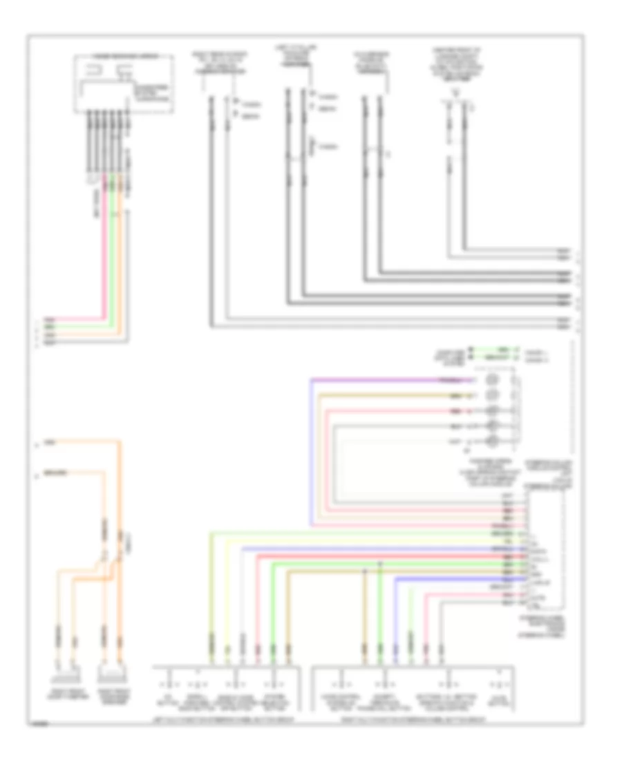 https://portal-diagnostov.com/license.html
Automotive Electricians Portal FZCO
Automotive Electricians Portal FZCO
https://portal-diagnostov.com/license.html
https://portal-diagnostov.com/license.html
Automotive Electricians Portal FZCO
Automotive Electricians Portal FZCOList of elements for COMAND Actuation Wiring Diagram (2 of 3) for Mercedes-Benz E250 Bluetec 4Matic 2014:
- (center front of luggage compt) (w/ navigation) global positioning system antenna splitter
- (left "c" pillar) fm2 & dab antenna amplifier
- (not used)
- (right rear of roof) fm1, am, cl (zv) & keyless go antenna amplifier
- (top of steering column)
- +,-
- Accept/ terminate phone call button
- Back & voice control system off button
- Buttons + & - setting specific function & volume control
- Can-e1 h
- Can-e1 l
- Computer data lines system
- Fanfare horns & air bag clock spring contact (part of steering column module)
- Gnd
- Hands-free system
- Inside rearview mirror
- Left multi-function steering wheel button group
- Microphone
- Mute
- Mute button
- Nca
- Ok button
- Pnk
- R,rtn
- Red
- Right front door bass speaker
- Right front door tweeter
- Right multi-function steering wheel button group
- Scroll forward/ back button
- Sedan
- Steering column module control unit
- Steering wheel electronics (inside steering wheel)
- System selection button
- Tel
- U-mfl-r
- U-mll-l
- Voice control system on button
- Wagon
- X35/2-c1
- X8/46-c2
COMAND Actuation Wiring Diagram (3 of 3) for Mercedes-Benz E250 Bluetec 4Matic 2014
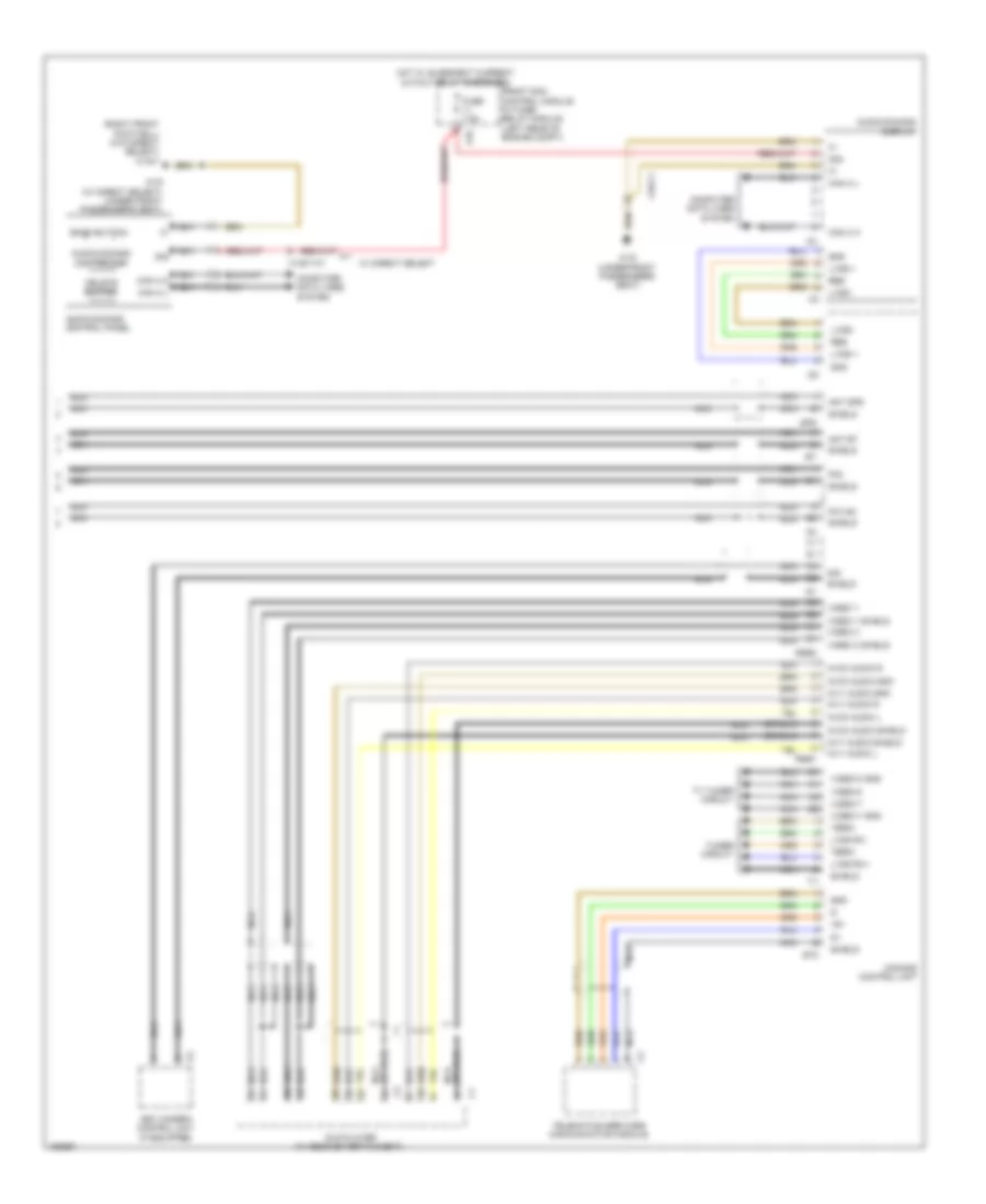 https://portal-diagnostov.com/license.html
Automotive Electricians Portal FZCO
Automotive Electricians Portal FZCO
https://portal-diagnostov.com/license.html
https://portal-diagnostov.com/license.html
Automotive Electricians Portal FZCO
Automotive Electricians Portal FZCOList of elements for COMAND Actuation Wiring Diagram (3 of 3) for Mercedes-Benz E250 Bluetec 4Matic 2014:
- (right front footwell) (w/o direct select) w15/7
- +5v
- 30g
- 360° camera control unit (if equipped)
- Ant bt
- Ant gps
- Audio/comand control panel
- Audio/comand controller
- Audio/comand display
- Avi1 audio gnd
- Avi1 audio l
- Avi1 audio r
- Avi1 audio shield
- Avo3 audio gnd
- Avo3 audio l
- Avo3 audio r
- Avo3 audio shield
- Back button
- C5c
- Can a h
- Can a l
- Comand control unit
- Computer data lines system
- Delete button
- Dvd player (w/ rear entertainment)
- Et2
- Fm1/am
- Fm2
- Front sam control module w/ fuse/ relay module (left rear of engine compt)
- Fuse 7.5a
- Gnd
- Gps
- Hot w/ quiescent current cutout relay energized
- Lvds +
- Lvds -
- Lvds rx+
- Lvds rx-
- Lvds-
- Nca
- Nca can a h
- Nca can a l
- Res
- Rse1
- Rse2
- Shield
- Sig
- Telematics services communication module
- Termi
- Tuner circuit
- Tv tuner circuit
- Video c
- Video c shield
- Video y
- Video y shield
- Video-c
- Video-c gnd
- Video-y
- Video-y gnd
- W/ direct select
- W19 (under front passenger's seat)
- W19 (w/ direct select) (under front passenger's seat)
- X138/1-c1
- X18-c1
DVD Player Wiring Diagram for Mercedes-Benz E250 Bluetec 4Matic 2014
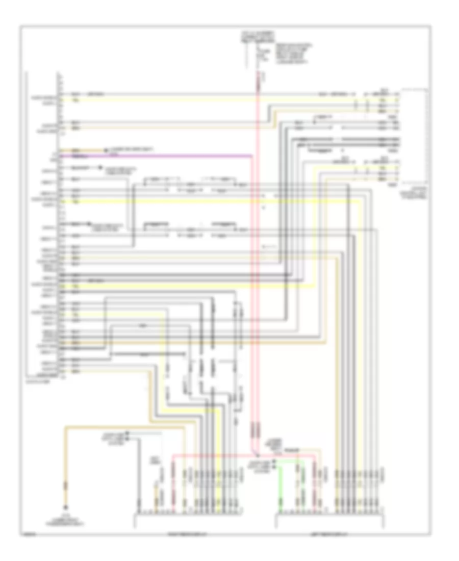 https://portal-diagnostov.com/license.html
Automotive Electricians Portal FZCO
Automotive Electricians Portal FZCO
https://portal-diagnostov.com/license.html
https://portal-diagnostov.com/license.html
Automotive Electricians Portal FZCO
Automotive Electricians Portal FZCOList of elements for DVD Player Wiring Diagram for Mercedes-Benz E250 Bluetec 4Matic 2014:
- (not used)
- (or nca)
- (under driver's seat) w18
- 30g
- Audio gnd
- Audio gnd vedio y shield
- Audio l
- Audio r
- Audio shield
- C11t
- Can-a h
- Can-a l
- Comand control unit (if equipped)
- Computer data lines system
- Dvd player
- Fuse 7.5a
- Hot w/ quiesent current cutout relay energized
- Left rear display
- Nca
- Rear sam control module w/ fuse/ relay module (right side of luggage compt)
- Right rear display
- Rse1
- Rse2
- Shield
- Vedio c
- Vedio c+
- Vedio c-
- Vedio y
- Vedio y+
- Vedio y-
- W19 (under front passenger's seat)
- X55/3-c8
- X55/3-c9
- X55/4-c8
- X55/4-c9
MOST Data Bus Wiring Diagram for Mercedes-Benz E250 Bluetec 4Matic 2014
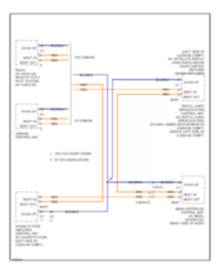 https://portal-diagnostov.com/license.html
Automotive Electricians Portal FZCO
Automotive Electricians Portal FZCO
https://portal-diagnostov.com/license.html
https://portal-diagnostov.com/license.html
Automotive Electricians Portal FZCO
Automotive Electricians Portal FZCOList of elements for MOST Data Bus Wiring Diagram for Mercedes-Benz E250 Bluetec 4Matic 2014:
- (left side of luggage compt) (w/ satellite digital audio radio (sdar)) sdar control unit/high definition tuner
- Comand control unit
- Digital audio broadcasting control unit (w/ digital audio broadcasting) (wagon: under center rear of luggage compt) (sedan: left side of luggage compt)
- Media interface control unit (w/ media interface) (right side of dash)
- Most
- Most in
- Most out
- Radio (w/ audio 20) radio w/ auto pilot system (w/ audio 50)
- Sound system amplifier control unit (w/ sound system) (left side of luggage compt)
- W/ advanced sound
- W/ comand
- W/o advanced sound
- W/o comand
- Wake up
- X18-c2
- X39/50-c2
Multimedia Interface Wiring Diagram for Mercedes-Benz E250 Bluetec 4Matic 2014
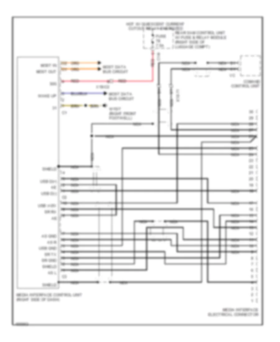 https://portal-diagnostov.com/license.html
Automotive Electricians Portal FZCO
Automotive Electricians Portal FZCO
https://portal-diagnostov.com/license.html
https://portal-diagnostov.com/license.html
Automotive Electricians Portal FZCO
Automotive Electricians Portal FZCOList of elements for Multimedia Interface Wiring Diagram for Mercedes-Benz E250 Bluetec 4Matic 2014:
- 30g
- As gnd
- As l
- As r
- C14i
- Comand control unit
- Fuse 7.5a
- Hot w/ quiescent current cutout relay energized
- Media interface control unit (right side of dash)
- Media interface electrical connector
- Most data bus circuit
- Most in
- Most out
- Nca
- Rear sam control unit w/ fuse & relay module (right side of luggage compt)
- Red
- Shield
- Sr gnd
- Sr rx
- Sr tx
- Usb (+)5v
- Usb d(+)
- Usb d(-)
- Usb gnd
- W15/7 (right front footwell)
- Wake up
- X18-71
- X18-c2
Radio Wiring Diagram (1 of 3) for Mercedes-Benz E250 Bluetec 4Matic 2014
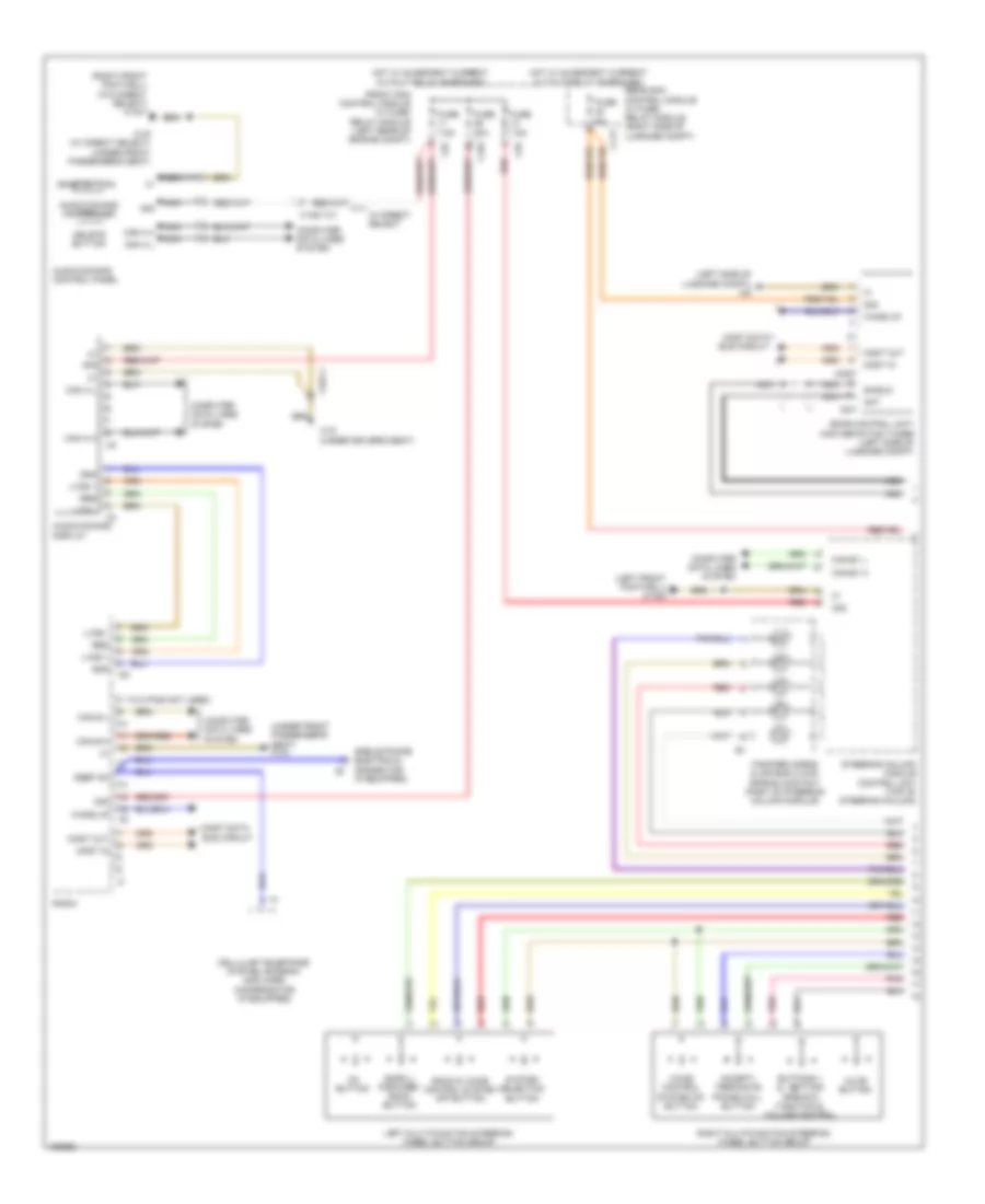 https://portal-diagnostov.com/license.html
Automotive Electricians Portal FZCO
Automotive Electricians Portal FZCO
https://portal-diagnostov.com/license.html
https://portal-diagnostov.com/license.html
Automotive Electricians Portal FZCO
Automotive Electricians Portal FZCOList of elements for Radio Wiring Diagram (1 of 3) for Mercedes-Benz E250 Bluetec 4Matic 2014:
- (1 to 8 pins not used)
- (left front footwell) w15/5
- (left side of luggage compt) w6
- (right front footwell) (w/o direct select) w15/7
- (under front passenger's seat) w19
- 30g
- Accept/ terminate phone call button
- Ant
- Audio/comand control panel
- Audio/comand controller
- Audio/comand display
- Back & voice control system off button
- Back button
- Buttons + & - setting specific function & volume control
- C10t
- C11t
- C5c
- Can a h
- Can a l
- Can b h
- Can b l
- Can-e1 h
- Can-e1 l
- Cellular telephone system antenna amplifier/ compensator (if equipped)
- Computer data lines system
- Delete button
- Fanfare horns & air bag clock spring contact (part of steering column module)
- Front sam control module w/ fuse/ relay module (left rear of engine compt)
- Fuse 20a
- Fuse 5a
- Fuse 7.5a
- Gnd
- Hot w/ quiescent current cutout relay energized
- Keep on
- Left multi-function steering wheel button group
- Lvds +
- Lvds -
- Mobile phone electrical connector (if equipped)
- Most
- Most data bus circuit
- Most in
- Most out
- Mute button
- Nca
- Ok button
- Pnk
- Radio
- Rear sam control module w/ fuse/ relay module (right side of luggage compt)
- Red
- Res
- Right multi-function steering wheel button group
- Sat
- Scroll forward/ back button
- Sdar control unit/ high definition tuner (left side of luggage compt)
- Shield
- Steering column module control unit (top of steering column)
- System selection button
- Voice control system on button
- W/ direct select
- W18 (under driver's seat)
- W19 (w/ direct select) (under front passenger's seat)
- Wake up
- X138/1-c1
- X18-c1
Radio Wiring Diagram (2 of 3) for Mercedes-Benz E250 Bluetec 4Matic 2014
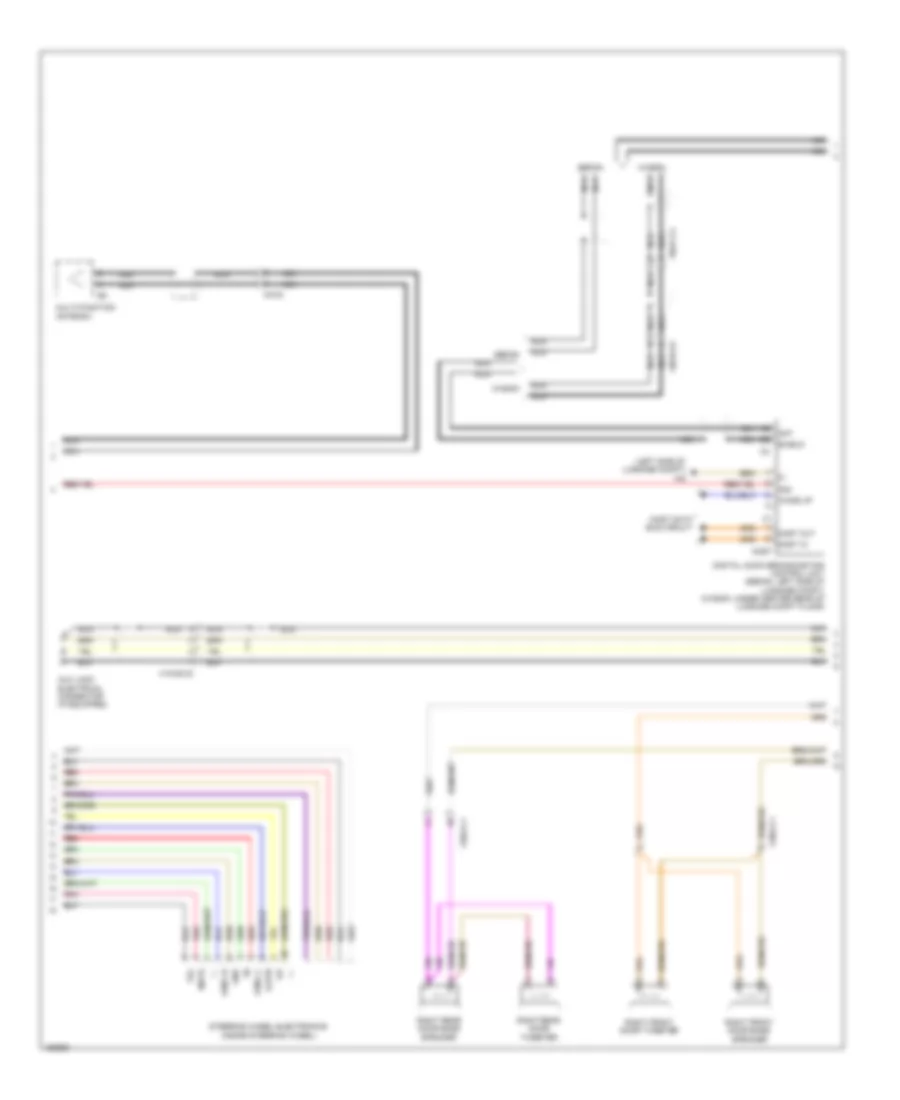 https://portal-diagnostov.com/license.html
Automotive Electricians Portal FZCO
Automotive Electricians Portal FZCO
https://portal-diagnostov.com/license.html
https://portal-diagnostov.com/license.html
Automotive Electricians Portal FZCO
Automotive Electricians Portal FZCOList of elements for Radio Wiring Diagram (2 of 3) for Mercedes-Benz E250 Bluetec 4Matic 2014:
- (left side of luggage compt) w6
- +,-
- 30g
- Ant
- Aux jack electrical connector (if equipped)
- Digital audio broadcasting control unit (sedan: left side of luggage compt) (wagon: under center rear of luggage compt floor)
- Gnd
- Most
- Most data bus circuit
- Most in
- Most out
- Multi-function antenna
- Mute
- Nca
- Pnk
- R,rtn
- Red
- Right front door bass speaker
- Right front door tweeter
- Right rear door bass speaker
- Right rear door tweeter
- Sedan
- Shield
- Steering wheel electronics (inside steering wheel)
- Tel
- U-mfl-r
- U-mll-l
- Wagon
- Wake up
- X18/35-c2
- X2-c2
- X35/2-c1
- X35/4-c1
- X8/45-c6
- X8/47-c3
Radio Wiring Diagram (3 of 3) for Mercedes-Benz E250 Bluetec 4Matic 2014
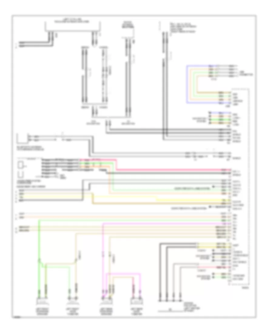 https://portal-diagnostov.com/license.html
Automotive Electricians Portal FZCO
Automotive Electricians Portal FZCO
https://portal-diagnostov.com/license.html
https://portal-diagnostov.com/license.html
Automotive Electricians Portal FZCO
Automotive Electricians Portal FZCOList of elements for Radio Wiring Diagram (3 of 3) for Mercedes-Benz E250 Bluetec 4Matic 2014:
- (+)
- (-)
- (left "c" pillar) fm2 & dab antenna amplifier
- (not used)
- Anst
- Aux1-gnd
- Aux1-l
- Aux1-r
- Aux1-s
- Can a h
- Can a l
- Comand fan motor (left center of dash)
- Computer data lines system
- Dab
- Diag
- Fl+
- Fl-
- Fm 1, am, cl (zv) & keyless go antenna amplifier (right rear of roof)
- Fm/tmc antenna splitter
- Fm1/am
- Fm2
- Fr+
- Fr-
- Gnd
- Hands free system microphone
- Inside rear view mirror
- Left front door bass speaker
- Left front door tweeter
- Left rear door bass speaker
- Left rear door tweeter
- Lvds +
- Lvds -
- Mic 1 +
- Mic 2 +
- Navi +
- Navi gnd
- Navi shield
- Navigation system
- Nca
- Pnk
- Radio
- Res
- Rl+
- Rl-
- Rr+
- Rr-
- Sedan
- Shield
- Usb
- Usb bus
- Usb connector
- Usb+
- Usb-
- Voice gnd
- Voice in
- Voice shield
- W/ navigation
- W/o navigation
- Wagon
- X115
- X120-c1
- X35/1-c1
- X35/3-c1
- X8/46-c2
Sound Amplifier Wiring Diagram, with Advanced Sound System (1 of 2) for Mercedes-Benz E250 Bluetec 4Matic 2014
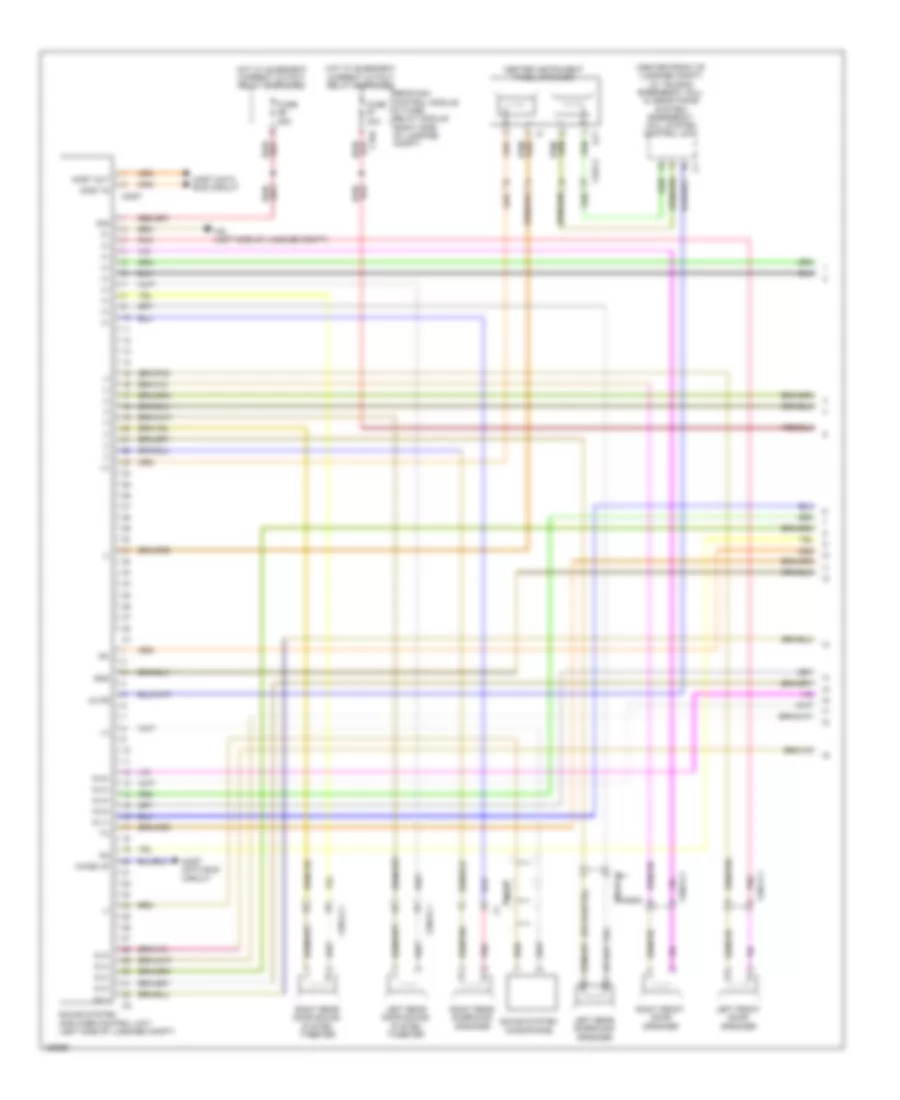 https://portal-diagnostov.com/license.html
Automotive Electricians Portal FZCO
Automotive Electricians Portal FZCO
https://portal-diagnostov.com/license.html
https://portal-diagnostov.com/license.html
Automotive Electricians Portal FZCO
Automotive Electricians Portal FZCOList of elements for Sound Amplifier Wiring Diagram, with Advanced Sound System (1 of 2) for Mercedes-Benz E250 Bluetec 4Matic 2014:
- (+)
- (-)
- (center front of luggage compt) (w/ teleaid emergency call & assistance system) emergency call system control unit
- 30g
- C15h
- Center instrument panel speaker
- Fuse 25a
- Fuse 40a
- Gnd
- Hot w/ quiescent current cutout relay energized
- In 1+
- In 1-
- In 2+
- In 2-
- In 3+
- In 3-
- In 4+
- In 4-
- In 5+
- In 5-
- Lct
- Left front door speaker
- Left rear door sound system tweeter
- Left rear surround speaker
- Most
- Most data bus circuit
- Most in
- Most out
- Mute
- Nca
- Pnk
- Rear sam control module w/ fuse/ relay module (right side of luggage compt)
- Right front door speaker
- Right rear door sound system tweeter
- Right rear surround speaker
- Sound system amplifier control unit (left side of luggage compt)
- Sound system microphone
- W6 (left side of luggage compt)
- Wagon
- Wake up
- X18-c2
- X35/1-c1
- X35/2-c1
- X35/3-c1
- X35/4-c1
- X8/45-c1
Sound Amplifier Wiring Diagram, with Advanced Sound System (2 of 2) for Mercedes-Benz E250 Bluetec 4Matic 2014
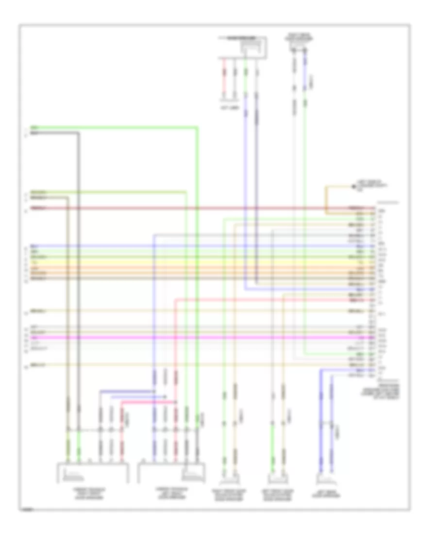 https://portal-diagnostov.com/license.html
Automotive Electricians Portal FZCO
Automotive Electricians Portal FZCO
https://portal-diagnostov.com/license.html
https://portal-diagnostov.com/license.html
Automotive Electricians Portal FZCO
Automotive Electricians Portal FZCOList of elements for Sound Amplifier Wiring Diagram, with Advanced Sound System (2 of 2) for Mercedes-Benz E250 Bluetec 4Matic 2014:
- (+)
- (-)
- (left side of luggage compt) w6
- 30g
- Bass speaker
- Gnd
- In 1+
- In 1-
- In 2+
- In 2-
- In 3+
- In 3-
- In 4+
- In 4-
- In 5+
- In 5-
- Left front door sound system bass speaker
- Left rear door speaker
- Mirror triangle left front door speaker
- Mirror triangle right front door speaker
- Not used
- Rear bass speaker amplifier (under left center of hat shelf)
- Red
- Right front door sound system bass speaker
- Right rear door speaker
- Sig
- X35/1-c1
- X35/1-c6
- X35/2-c1
- X35/2-c6
- X35/3-c1
- X35/4-c1
Sound Amplifier Wiring Diagram, without Advanced Sound System (1 of 2) for Mercedes-Benz E250 Bluetec 4Matic 2014
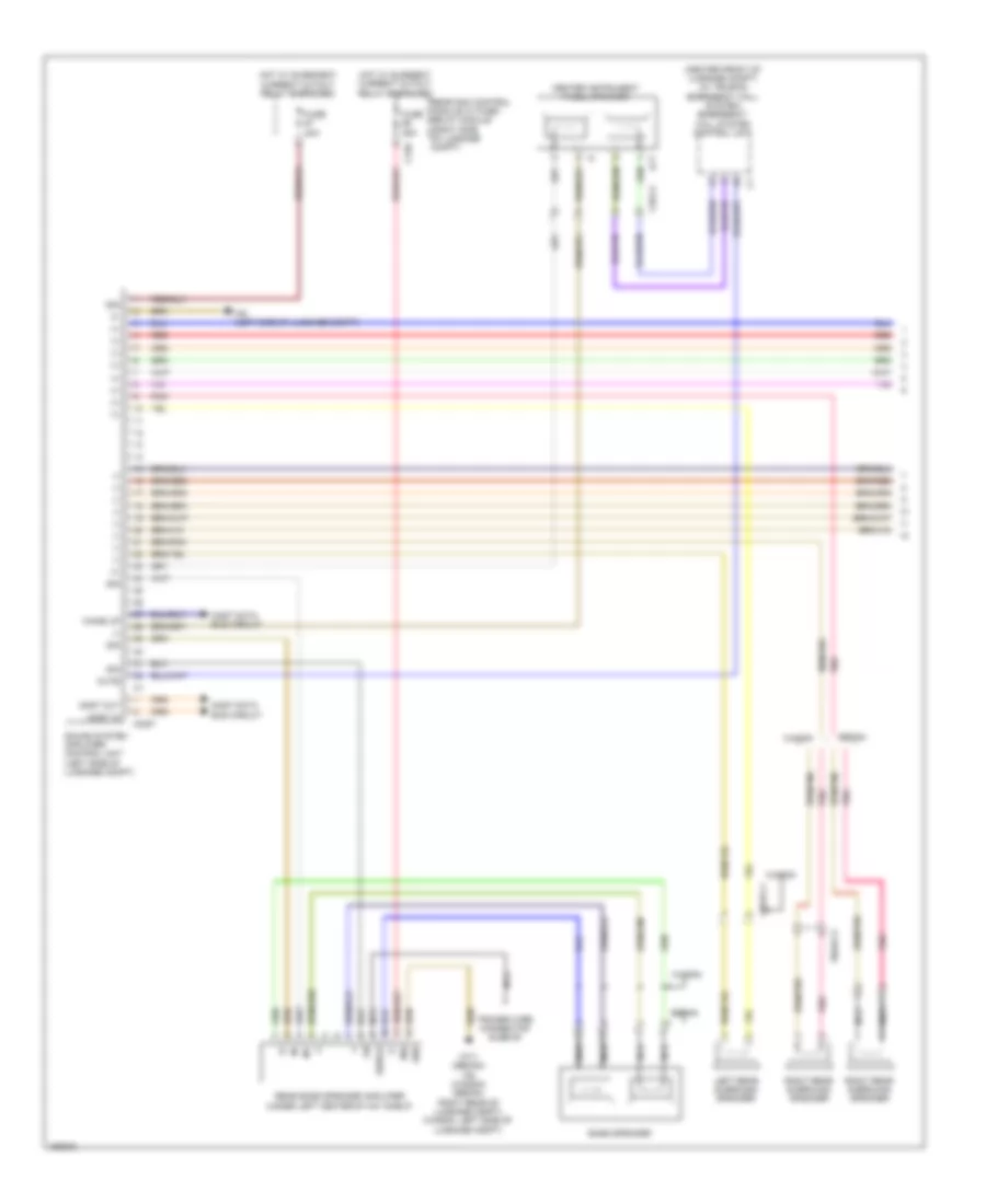 https://portal-diagnostov.com/license.html
Automotive Electricians Portal FZCO
Automotive Electricians Portal FZCO
https://portal-diagnostov.com/license.html
https://portal-diagnostov.com/license.html
Automotive Electricians Portal FZCO
Automotive Electricians Portal FZCOList of elements for Sound Amplifier Wiring Diagram, without Advanced Sound System (1 of 2) for Mercedes-Benz E250 Bluetec 4Matic 2014:
- (+)
- (-)
- (center front of luggage compt) (w/ teleaid emergency call system) emergency call system control unit
- 30g
- Bass speaker
- C15h
- Center instrument panel speaker
- Fuse 25a
- Fuse 40a
- Gnd
- Hot w/ quiescent current cutout relay energized
- Hot w/ quiesent current cutout relay energized
- In+
- In-
- Lct
- Left rear surround speaker
- Most
- Most data bus circuit
- Most in
- Most out
- Mute
- Nca
- Pnk
- Rear bass speaker amplifier (under left center of hat shelf)
- Rear sam control module w/ fuse/ relay module (right side of luggage compt)
- Red
- Right rear surround speaker
- Sedan
- Shield
- Sig
- Sound system amplifier control unit (left side of luggage compt)
- Tracer wire connector sleeve
- W6 (left side of luggage compt)
- W7/1 (sedan) w6 (wagon) (sedan: right rear of luggage compt) (wagon: left side of luggage compt)
- Wagon
- Wake up
- X18-c2
- X8/45-c1
- X8/46-c3
Sound Amplifier Wiring Diagram, without Advanced Sound System (2 of 2) for Mercedes-Benz E250 Bluetec 4Matic 2014
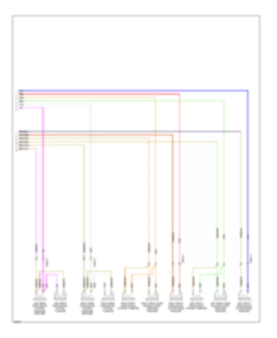 https://portal-diagnostov.com/license.html
Automotive Electricians Portal FZCO
Automotive Electricians Portal FZCO
https://portal-diagnostov.com/license.html
https://portal-diagnostov.com/license.html
Automotive Electricians Portal FZCO
Automotive Electricians Portal FZCOList of elements for Sound Amplifier Wiring Diagram, without Advanced Sound System (2 of 2) for Mercedes-Benz E250 Bluetec 4Matic 2014:
- Left front door sound system bass speaker
- Left front door sound system midrange speaker
- Left front door sound system tweeter
- Left rear door sound system midrange speaker
- Left rear door sound system tweeter
- Red
- Right front door sound system bass speaker
- Right front door sound system midrange speaker
- Right front door sound system tweeter
- Right rear door sound system midrange speaker
- Right rear door sound system tweeter
- X35/1-c1
- X35/2-c1
- X35/3-c1
- X35/4-c1
TV Tuner Wiring Diagram for Mercedes-Benz E250 Bluetec 4Matic 2014
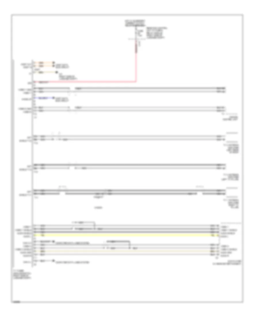 https://portal-diagnostov.com/license.html
Automotive Electricians Portal FZCO
Automotive Electricians Portal FZCO
https://portal-diagnostov.com/license.html
https://portal-diagnostov.com/license.html
Automotive Electricians Portal FZCO
Automotive Electricians Portal FZCOList of elements for TV Tuner Wiring Diagram for Mercedes-Benz E250 Bluetec 4Matic 2014:
- 30g
- Ant
- Audio gnd
- Audio l
- Audio r
- Audio shield
- C11t
- Can a h
- Can a l
- Comand control unit
- Computer data lines system
- Dvd player (w/ rear entertainment)
- Fuse 7.5a
- Hot w/ quiescent current cutout relay energized
- Most
- Most data bus circuit
- Most in
- Most out
- Nca
- Rear sam control unit w/ fuse & relay module (right side of luggage compt)
- Shield tv1
- Shield tv2
- Shield tv3
- Tv 1 antenna amplifier (right "c" pillar)
- Tv 2 antenna amplifier (left rear of roof)
- Tv 3 antenna amplifier (left "a" pillar)
- Tv tuner (analog/digital) (right side of luggage compt)
- Tv1
- Tv2
- Tv3
- Video c
- Video c shield
- Video y
- Video y gnd
- Video y shield
- Video-c
- Video-c gnd
- W7 (right side of luggage compt)
- Wagon
- Wake up
- X48/45-c7
Tuner Wiring Diagram for Mercedes-Benz E250 Bluetec 4Matic 2014
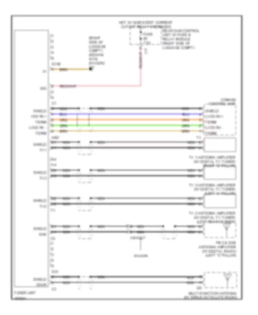 https://portal-diagnostov.com/license.html
Automotive Electricians Portal FZCO
Automotive Electricians Portal FZCO
https://portal-diagnostov.com/license.html
https://portal-diagnostov.com/license.html
Automotive Electricians Portal FZCO
Automotive Electricians Portal FZCOList of elements for Tuner Wiring Diagram for Mercedes-Benz E250 Bluetec 4Matic 2014:
- (right side of luggage compt) (sedan) w7/8 (wagon) w7
- 11t
- 30g
- Comand control unit
- Dab
- Fm 2 & dab antenna amplifier (w/ digital radio) (left "c" pillar)
- Fuse 7.5a
- Hot w/ quiescent current cutout relay energized
- Hsd
- Lvds rx -
- Lvds rx+
- Lvds rx-
- Multi-function antenna (w/ sirius satellite radio)
- Nca
- Rear sam control unit w/ fuse & relay module (right side of luggage compt)
- S31b
- S33
- Sdar
- Shield
- Termi
- Tuner unit
- Tv 1 antenna amplifier (w/ digital tv tuner) (right "c" pillar)
- Tv 2 antenna amplifier (w/ digital tv tuner) (left rear of roof)
- Tv 3 antenna amplifier (w/ digital tv tuner) (left "a" pillar)
- Tv1
- Tv2
- Tv3
- Vds rx+
- Wagon
- X8/47-c7
SHIFT INTERLOCK
Shift Interlock Wiring Diagram for Mercedes-Benz E250 Bluetec 4Matic 2014
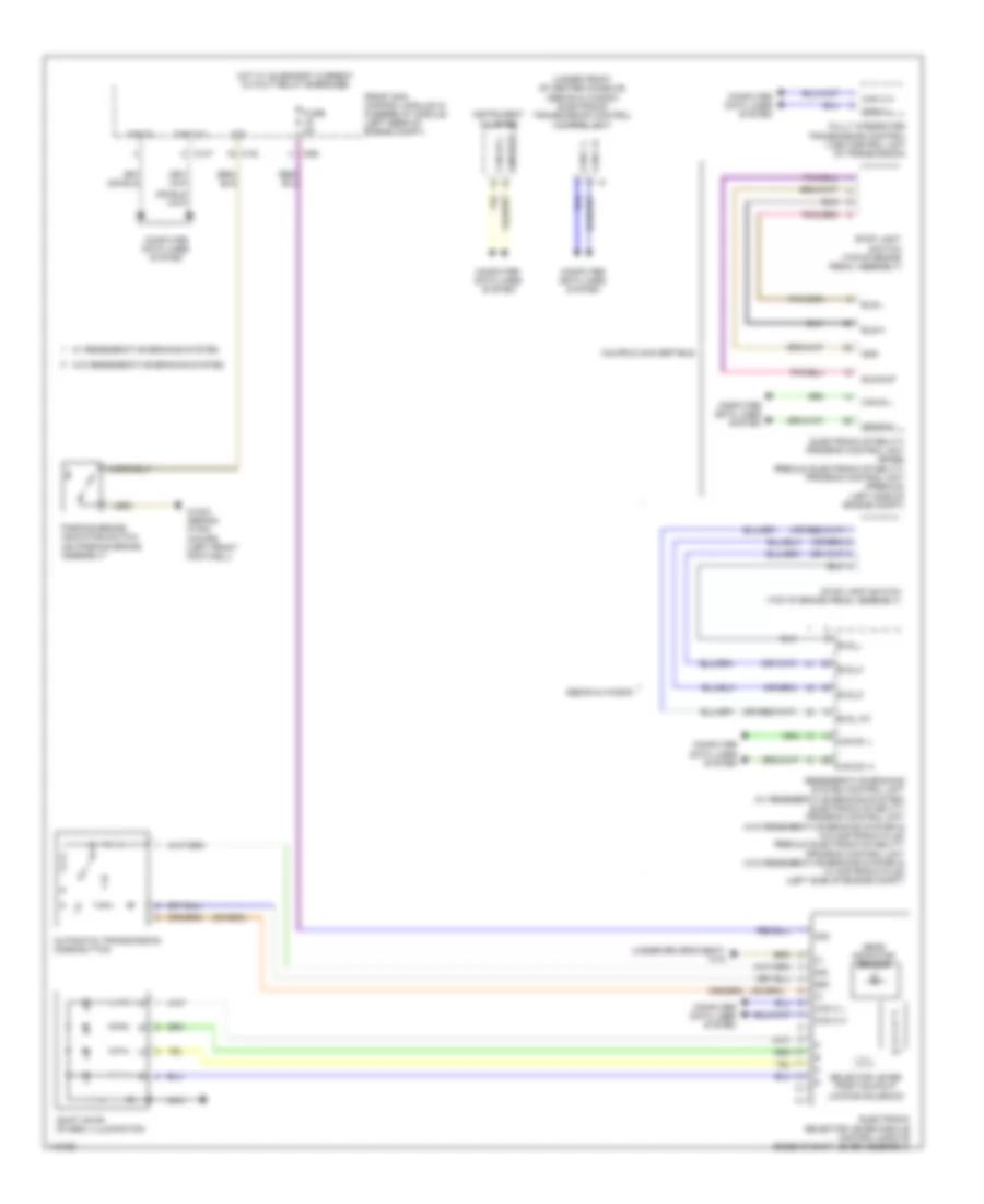 https://portal-diagnostov.com/license.html
Automotive Electricians Portal FZCO
Automotive Electricians Portal FZCO
https://portal-diagnostov.com/license.html
https://portal-diagnostov.com/license.html
Automotive Electricians Portal FZCO
Automotive Electricians Portal FZCOList of elements for Shift Interlock Wiring Diagram for Mercedes-Benz E250 Bluetec 4Matic 2014:
- (under driver's seat) w18
- (under front of center console) (sedan & wagon) electronic transmission control control unit
- 30g
- 58d
- Automatic transmission mode button
- Bls-h
- Bls-l
- Bls-sup
- Bls_12v
- Bls_h
- Bls_l
- Bls_m
- C10t
- C19i
- C9g
- Can c h
- Can c l
- Can d h
- Can d l
- Can e h
- Can e l
- Can e1 h
- Can e1 l
- Can e2 h
- Can e2 l
- Computer data lines system
- Coupe & convertible
- Electronic selector lever module control module (base of shift lever assembly)
- Electronic stability program control unit (base) premium electronic stability program control unit (premium) (left side of engine compt)
- Front sam control module w/ fuse/relay module (left rear of engine compt)
- Fully integrated transmission control (vgs) control unit (in transmission)
- Fuse 5a
- Gear indicator sensor
- Gnd
- Hot w/ quiescent current cutout relay energized
- Instrument cluster
- Nca
- P r n d- d+
- Parking brake indicator switch (on parking brake assembly)
- Regenerative braking system control unit (w/ regenerative braking system) electronic stability program control unit (w/o regenerative braking system & w/o distronic plus) premium electronic stability program control unit (w/o regenerative braking system & w/ distronic plus) (left side of engine compt)
- Sedan & wagon
- Selector lever position r & p locking solenoid
- Shift gate symbol illumination
- Sig
- Stop light switch (top of brake pedal assembly)
- W/ regenerative braking system
- W/o regenerative braking system
- W15/2 (sedan) w15/5 (coupe) (left front footwell)
STARTING/CHARGING
Charging Wiring Diagram for Mercedes-Benz E250 Bluetec 4Matic 2014
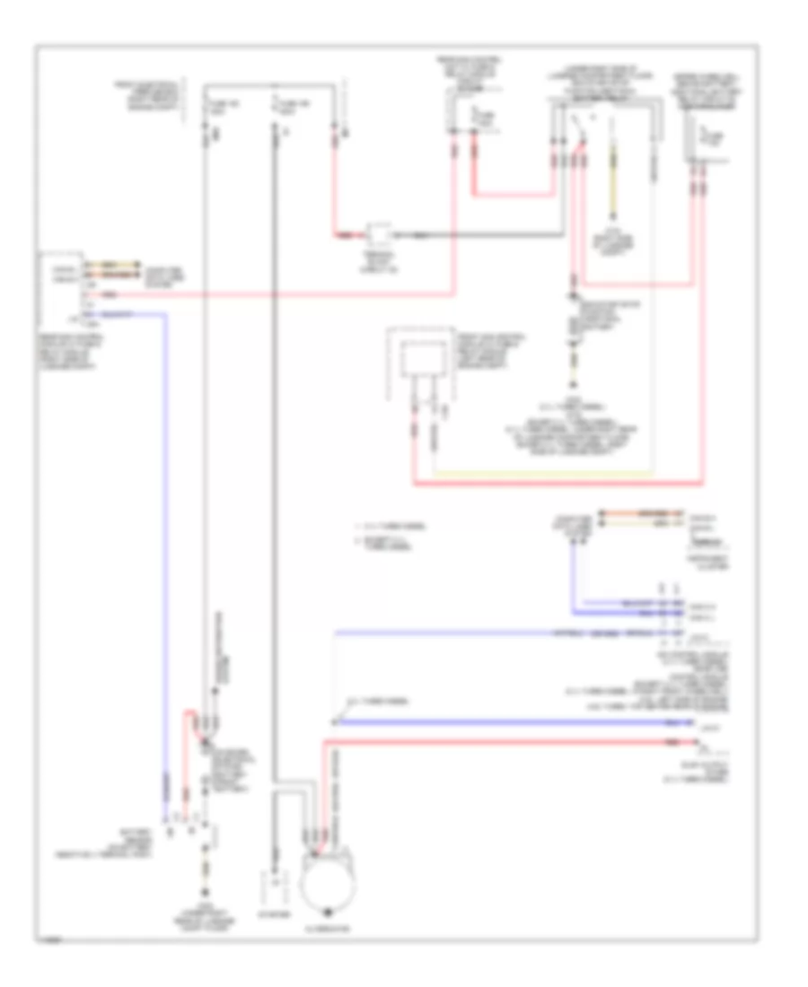 https://portal-diagnostov.com/license.html
Automotive Electricians Portal FZCO
Automotive Electricians Portal FZCO
https://portal-diagnostov.com/license.html
https://portal-diagnostov.com/license.html
Automotive Electricians Portal FZCO
Automotive Electricians Portal FZCOList of elements for Charging Wiring Diagram for Mercedes-Benz E250 Bluetec 4Matic 2014:
- (spare wheelwell behind battery) additional battery relay circuit 30 additional fuse
- (under right side of luggage compartment floor) eco start/stop function additional battery relay
- 2.1l turbo diesel
- Alternator
- C19i
- C5h
- C9i
- Can b h
- Can b l
- Can c h
- Can c l
- Cdi control module (2.1l turbo diesel) me-sfi (me) control module (except 2.1l turbo diesel) (2.1l turbo diesel: in right front wheelwell) (3.5l: left side of engine) (4.6l turbo: top center rear of engine)
- Computer data lines system
- Display
- Eco start/stop function additional battery
- Except 2.1l
- Front electrical prefuse box (right rear of engine compt)
- Front sam control module w/ fuse & relay module (left rear of engine compt)
- Fuse 100a
- Fuse 150 150a
- Fuse 159 400a
- Fuse 7.5a
- Glow output stage (2.1l turbo diesel)
- Im1
- Instrument cluster
- Lin
- Lin c1
- Mr8
- On board electrical system battery (front battery)
- Power distribution system
- Rear sam control module w/ fuse & relay module (right side of luggage compt)
- Rear sam control unit w/ fuse & relay module circuit 30 fuse
- Red
- Starter
- Terminal block (circuit 30)
- Turbo diesel
- W7/8 (right side of luggage compt)
- W8/8 (2.1l turbo diesel) w7/6 (excep 2.1l turbo diesel) (2.1l turbo diesel: under right rear of luggage compartment floor) (excep 2.1l turbo diesel: right side of luggage compt)
- W8/8 (under right rear of luggage compt floor)
Starting Wiring Diagram for Mercedes-Benz E250 Bluetec 4Matic 2014
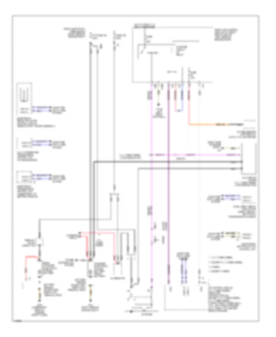 https://portal-diagnostov.com/license.html
Automotive Electricians Portal FZCO
Automotive Electricians Portal FZCO
https://portal-diagnostov.com/license.html
https://portal-diagnostov.com/license.html
Automotive Electricians Portal FZCO
Automotive Electricians Portal FZCOList of elements for Starting Wiring Diagram for Mercedes-Benz E250 Bluetec 4Matic 2014:
- (right side of engine compt)
- 2.1l turbo diesel
- 2.1l turbo diesel late production
- Alternator
- C15m
- C3m
- C4i
- C6i
- Can b h
- Can b l
- Can c h
- Can c l
- Cdi control module (2.1l turbo diesel) me-sfi (me) control module (except 2.1l turbo diesel) (2.1l turbo diesel: in right front wheelwell) (3.5l: left side of engine) (4.6l turbo: top center rear of engine)
- Charging circuit
- Computer data lines system
- Electronic ignition switch control unit
- Electronic selector lever control module (base of shift lever assembly)
- Electronic transmission control unit (under front of center console)
- Except 2.1l turbo diesel
- Except hybrid
- Front electrical prefuse box (right rear of engine compt)
- Front sam control module w/ fuse & relay module (left rear of engine compt)
- Fully integrated transmission control unit (in transmission)
- Fuse 159 400a
- Fuse 15a
- Fuse 20a
- Hot w/ circuit 15 relay energized
- Hybrid
- Hybrid except
- Intelligent servo module for direct select (bottom of transmission housing)
- Mr8
- Nca
- On board electrical system battery (front battery)
- Oxygen sensor upstream of catalytic converter
- P r n d- d+
- Power distribution system
- Pytfuse 150 150a
- Rear on board electrical system battery
- Red
- Starter
- Starter circuit relay
- Str
- Terminal block (circuit 30)
- Voltage dip limiter (2.1l turbo diesel late production)
- W10 (right rear of engine compt)
- W15/5 (left front footwell)
- W8/8 (under right rear of luggage compt floor)
- X25/2-c4
- X26-c1
SUPPLEMENTAL RESTRAINTS
Emergency Seat Belt Tensioners Wiring Diagram for Mercedes-Benz E250 Bluetec 4Matic 2014
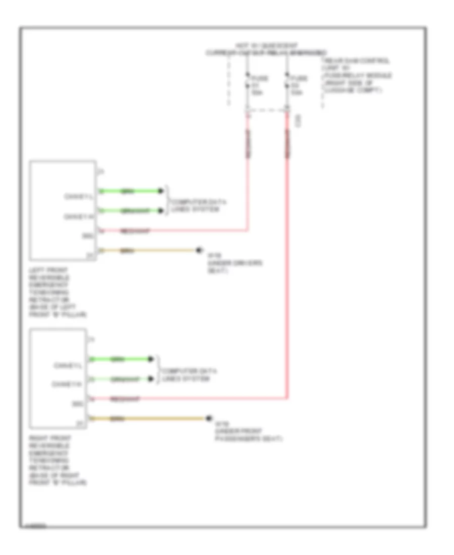 https://portal-diagnostov.com/license.html
Automotive Electricians Portal FZCO
Automotive Electricians Portal FZCO
https://portal-diagnostov.com/license.html
https://portal-diagnostov.com/license.html
Automotive Electricians Portal FZCO
Automotive Electricians Portal FZCOList of elements for Emergency Seat Belt Tensioners Wiring Diagram for Mercedes-Benz E250 Bluetec 4Matic 2014:
- 30g
- C2g
- Can e1 h
- Can e1 l
- Can-e1 h
- Can-e1 l
- Computer data lines system
- Fuse 50a
- Hot w/ quiescent current cutout relay energized
- Left front reversible emergency tensioning retractor (base of left front "b" pillar)
- Rear sam control unit w/ fuse/relay module (right side of luggage compt)
- Right front reversible emergency tensioning retractor (base of right front "b" pillar)
- W18 (under driver's seat)
- W19 (under front passenger's seat)
Supplemental Restraint Wiring Diagram (1 of 4) for Mercedes-Benz E250 Bluetec 4Matic 2014
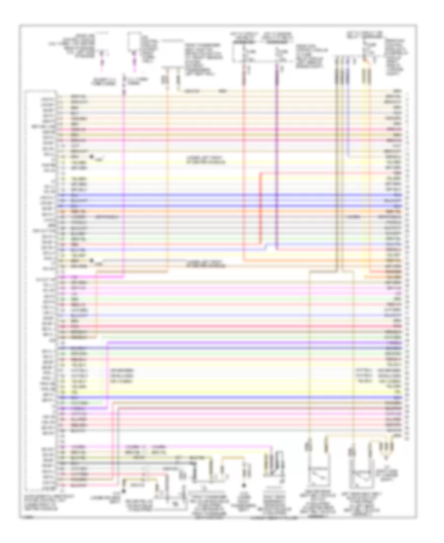 https://portal-diagnostov.com/license.html
Automotive Electricians Portal FZCO
Automotive Electricians Portal FZCO
https://portal-diagnostov.com/license.html
https://portal-diagnostov.com/license.html
Automotive Electricians Portal FZCO
Automotive Electricians Portal FZCOList of elements for Supplemental Restraint Wiring Diagram (1 of 4) for Mercedes-Benz E250 Bluetec 4Matic 2014:
- (+)
- (-)
- (in right rear "c" pillar)
- (or 3)
- (under left front of center console)
- 2.1l turbo diesel
- C11c
- C3i
- C5c
- C9i
- Cak bf
- Cak fa
- Cdi control module (in right front f wheel- well)
- Center rear seat belt buckle switch (if equipped) (in center rear seat belt buckle assembly)
- Ch out an
- Csh out dig
- Driver pelvis air bag squib (if equipped)
- Ds bf +
- Ds bf -
- Ds fa +
- Ds fa -
- Ds hl+
- Ds hl-
- Ds hr +
- Ds hr -
- Except 2.1l turbo diesel
- Front passenger pelvis air bag squib (if equipped) (outer edge of front passenger seat cushion)
- Front passenger seat position detection switch (w/ weight sensing system) (on front passenger's left seat rail)
- Front sam control module w/ fuse/ relay module (left rear of engine compt)
- Fs vl+
- Fs vl-
- Fs vm+
- Fs vm-
- Fs vr+
- Fs vr-
- Fuse 7.5a
- Gs bf +
- Gs bf -
- Gs fa+
- Gs fa-
- Gs hl +
- Gs hl -
- Gs hr +
- Gs hr -
- Gss bf
- Gss fa
- Hot w/ circuit 15r relay 1 energized
- Hot w/ circuit 15r relay energized
- Hot w/ engine circuit 87 relay energized
- Left rear seat belt buckle switch (if equipped) (in left rear seat belt buckle assembly)
- Lin e 2
- Me-sfi (me) control module (4.6l turbo: top center rear of engine) (3.5l: left side of engine)
- Mhs li
- Mhs re
- Nca
- Pb bf +
- Pb bf -
- Pb fa +
- Pb fa -
- Pnk
- Pps+ li
- Pps+ re
- Pps- li
- Pps- re
- Rear sam control module w/ fuse/relay module (right side of luggage compt)
- Red
- Return line
- Right rear emergency tensioning retractor squib (if equipped)
- Sb bf +
- Sb bf -
- Sb fa +
- Sb fa -
- Sb hl +
- Sb hl -
- Sb hr +
- Sb hr -
- Sbr
- Sig
- Ss bf +
- Ss bf -
- Ss fa +
- Ss fa -
- Ufs bf +
- Ufs bf -
- Ufs fa +
- Ufs fa -
- W18 (under driver's seat)
- W19 (under front passenger's seat)
- W26
- W7 (right side of luggage compt)
- Wb vl+
- Wb vl-
- Wb vr+
- Wb vr-
- X28/48
- X55/3-c2
- X55/4-c2
- X55/4-c3
Supplemental Restraint Wiring Diagram (2 of 4) for Mercedes-Benz E250 Bluetec 4Matic 2014
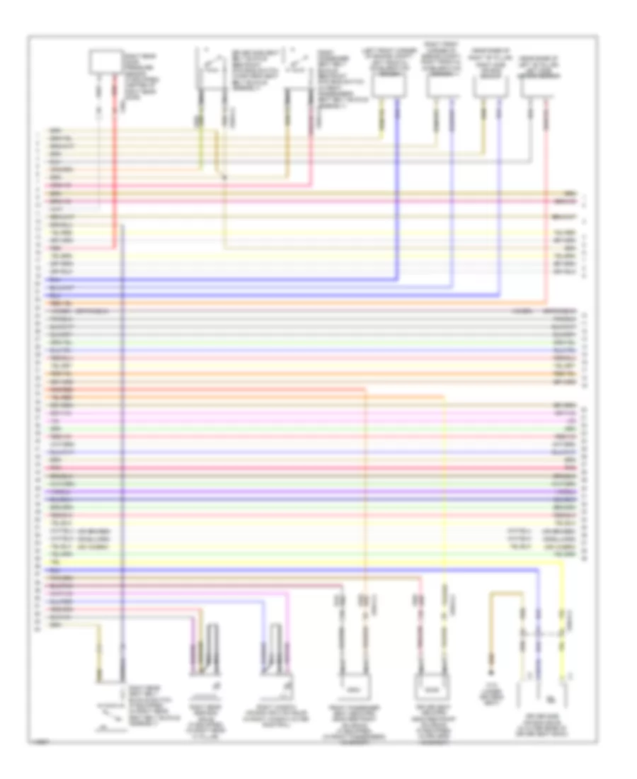 https://portal-diagnostov.com/license.html
Automotive Electricians Portal FZCO
Automotive Electricians Portal FZCO
https://portal-diagnostov.com/license.html
https://portal-diagnostov.com/license.html
Automotive Electricians Portal FZCO
Automotive Electricians Portal FZCOList of elements for Supplemental Restraint Wiring Diagram (2 of 4) for Mercedes-Benz E250 Bluetec 4Matic 2014:
- (left front corner of engine compt) left frontal acceleration sensor
- (near base of
- (near base of left "b" pillar) left side air bag sensor
- (or 3)
- (right front corner of engine compt) right frontal acceleration sensor
- Driver seat neck-pro head restraint solenoid (if equipped) (in driver's headrest)
- Driver side air bag squib (in outer edge of driver seat back)
- Driver side seat belt buckle restraint systems switch (in driver's seat belt buckle assembly)
- Front passenger seat belt buckle restraint systems switch (in front passenger's seat belt buckle assembly) x55/4-c2
- Front passenger seat neck-pro head restraint solenoid (if equipped) (in front passenger's headrest)
- Nca
- Pnk
- Red
- Right "b" pillar)
- Right rear door pressure sensor (if equipped) (center of right rear door)
- Right rear seat belt buckle switch (if equipped) (in right rear seat belt buckle assembly)
- Right rear side bag squib (if equipped) (in right rear "c" pillar)
- Right side air bag sensor
- Right window air bag ignition squib (in right window outer roof rail)
- W18 (under driver's seat)
- X35/4
- X55/3-c2
- X55/4-c2
Supplemental Restraint Wiring Diagram (3 of 4) for Mercedes-Benz E250 Bluetec 4Matic 2014
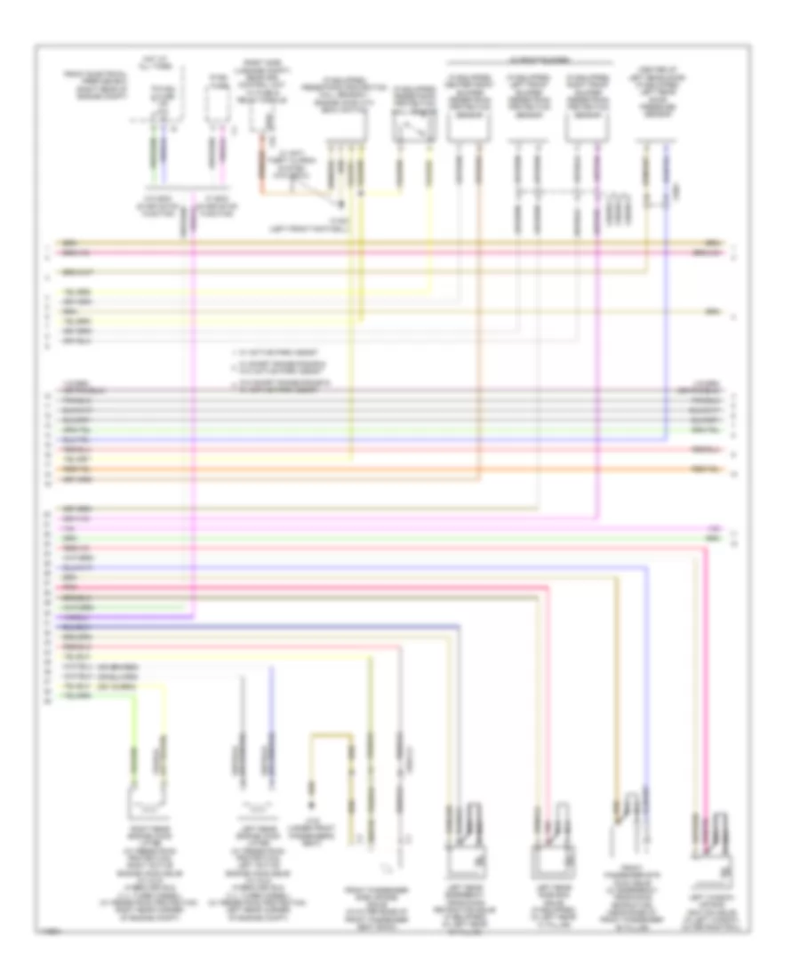 https://portal-diagnostov.com/license.html
Automotive Electricians Portal FZCO
Automotive Electricians Portal FZCO
https://portal-diagnostov.com/license.html
https://portal-diagnostov.com/license.html
Automotive Electricians Portal FZCO
Automotive Electricians Portal FZCOList of elements for Supplemental Restraint Wiring Diagram (3 of 4) for Mercedes-Benz E250 Bluetec 4Matic 2014:
- (center of left rear door) (if equipped) left rear door pressure sensor
- (if equipped) center front bumper pedestrian protection sensor
- (if equipped) left front bumper pedestrian protection sensor
- (if equipped) pedestrian protection hall sensor
- (if equipped) pedestrian protection hall sensor + engine hood ata (edw) switch
- (if equipped) right front bumper pedestrian protection sensor
- (in front bumper)
- (or 3)
- (right side luggage compt) rear sam control unit w/ fuse & relay module
- C9i
- Edw
- Front electrical prefuse box (right rear of engine compt)
- Front passenger etr (gus) squib (w/ emergency tensioning retractor) (near base of front passenger "b" pillar)
- Front passenger side air bag squib (in outer edge of front passenger seat back)
- Hot at all times
- Left rear emergency tensioning retractor squib (if equipped) (in left rear "c" pillar)
- Left rear engine hood lifter (w/ pedestrian protection) left active engine hood squib (w/ mild hybrid drive & 2.1l turbo diesel) (w/ pedestrian protection: left rear corner of engine compt)
- Left rear side bag squib (if equipped) (in left rear "c" pillar)
- Left window air bag ignition squib (in left window outer roof rail)
- Nca
- Pnk
- Pyro fuse
- Pyro fuse n/a
- Right rear engine hood lifter (w/ pedestrian protection) right active engine hood squib (w/ mild hybrid drive & 2.1l turbo diesel) (w/ pedestrian protection: right rear corner of engine compt)
- W/ active park assist
- W/ anti theft alaram system (ata (edw))
- W/ eco start/stop function
- W/ short range radar & w/o active park assist
- W/o eco start/stop function
- W/o short range radar & w/ active park assist
- W15/2 (left front footwell)
- W19 (under front passenger's seat)
- X26/38-c1
- X26/38-c2
- X26/38-c3
- X35/3
- X55/4-c2
Supplemental Restraint Wiring Diagram (4 of 4) for Mercedes-Benz E250 Bluetec 4Matic 2014
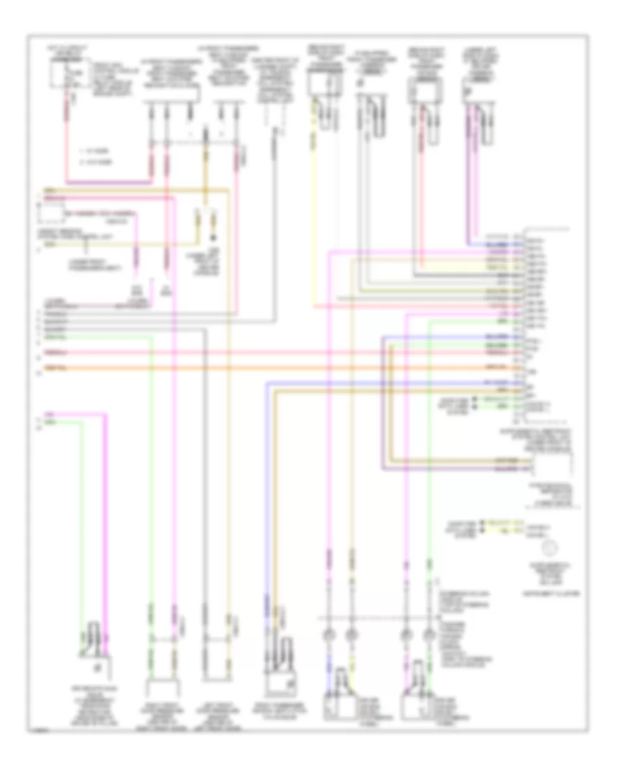 https://portal-diagnostov.com/license.html
Automotive Electricians Portal FZCO
Automotive Electricians Portal FZCO
https://portal-diagnostov.com/license.html
https://portal-diagnostov.com/license.html
Automotive Electricians Portal FZCO
Automotive Electricians Portal FZCOList of elements for Supplemental Restraint Wiring Diagram (4 of 4) for Mercedes-Benz E250 Bluetec 4Matic 2014:
- (behind right side of dash) front passenger air bag squib 1
- (behind right side of dash) front passenger air bag squib 2
- (center front of luggage compt) (w/ teleaid emergency call system) emergency call system control unit
- (if equipped) front passenger kneebag squib
- (in front passenger's seat cushion) (if equipped) front passenger seat occupied recognition
- (in front passenger's seat cushion) front passenger seat occupied recognition & acsr
- (or 3)
- (under front passenger's seat)
- (under left side of dash) (if equipped) driver kneebag squib
- 15r
- Ab1 bf+
- Ab1 bf-
- Ab1 fa+
- Ab1 fa-
- Ab2 bf+
- Ab2 bf-
- Ab2 fa+
- Ab2 fa-
- Bf+
- Bf-
- C10t
- Can e1 h can e1 l
- Can e2 h
- Can e2 l
- Computer data lines system
- Driver air bag squib 1 (in steering wheel)
- Driver air bag squib 2 (in steering wheel)
- Driver etr (gus) squib (w/ emergency tensioning retractor) (near base of driver "b" pillar)
- Fanfare horns & air bag clock spring contact (part of steering column module)
- Front passenger air bag ventilation valve squib
- Front sam control module w/ fuse/ relay module (left rear of engine compt)
- Fuse 7.5a
- Hot w/ circuit 15r relay energized
- Instrument cluster
- Kb bf+
- Kb bf-
- Kb fa+
- Kb fa-
- Left front door pressure sensor (center of left front door)
- Nca
- Pte +
- Pte -
- Pyrotechnical separator (w/ mild hybrid drive)
- Right front door pressure sensor (center of right front door)
- Steering column module (top of steering column)
- W/ acsr
- W/ ece
- W/o acsr
- W/o ece
- W26 (under left front of center console)
- Weight sensing system (wss) control unit
- X28/12-c1
- X35/1-c1
- X35/2-c1
- X55/4-c2
Weight Sensing System Wiring Diagram for Mercedes-Benz E250 Bluetec 4Matic 2014
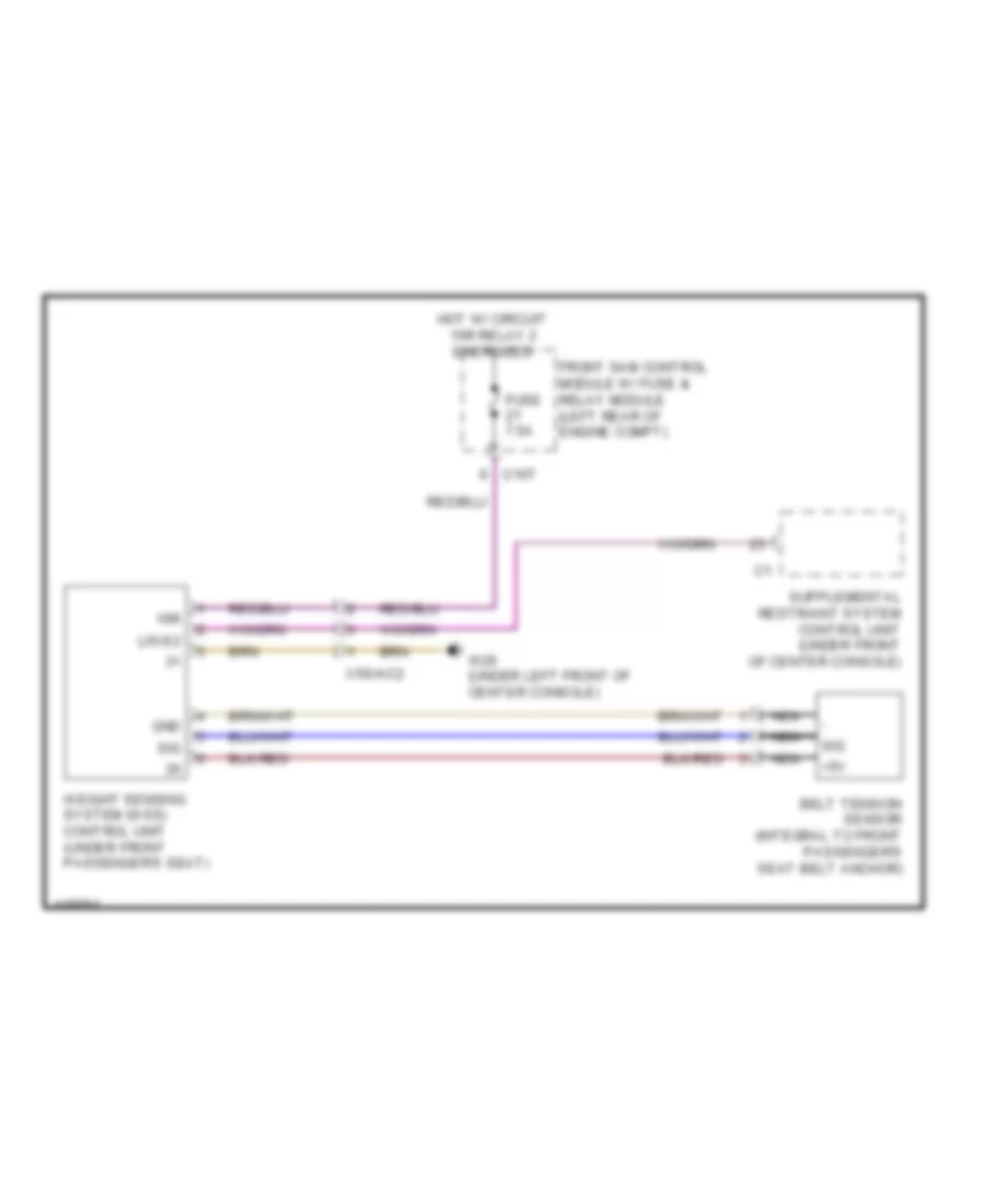 https://portal-diagnostov.com/license.html
Automotive Electricians Portal FZCO
Automotive Electricians Portal FZCO
https://portal-diagnostov.com/license.html
https://portal-diagnostov.com/license.html
Automotive Electricians Portal FZCO
Automotive Electricians Portal FZCOList of elements for Weight Sensing System Wiring Diagram for Mercedes-Benz E250 Bluetec 4Matic 2014:
- +5v
- 15r
- Belt tension sensor (integral to front passenger's seat belt anchor)
- C10t
- Front sam control module w/ fuse & relay module (left rear of engine compt)
- Fuse 7.5a
- Gnd
- Hot w/ circuit 15r relay 2 energized
- Lin e2
- Nca
- Sig
- W26 (under left front of center console)
- Weight sensing system (wss) control unit (under front passenger's seat)
- X55/4-c2
TRANSMISSION
Transmission Wiring Diagram (1 of 2) for Mercedes-Benz E250 Bluetec 4Matic 2014
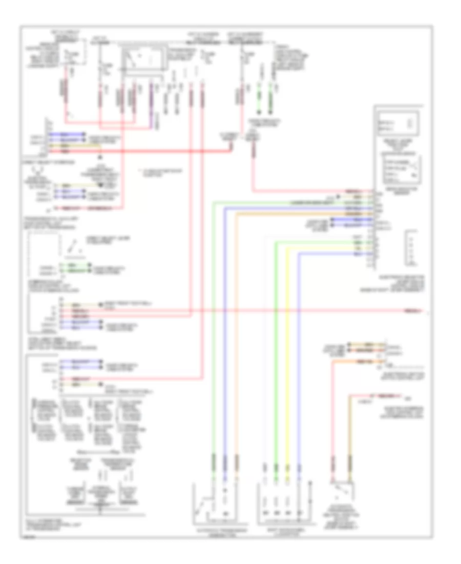 https://portal-diagnostov.com/license.html
Automotive Electricians Portal FZCO
Automotive Electricians Portal FZCO
https://portal-diagnostov.com/license.html
https://portal-diagnostov.com/license.html
Automotive Electricians Portal FZCO
Automotive Electricians Portal FZCOList of elements for Transmission Wiring Diagram (1 of 2) for Mercedes-Benz E250 Bluetec 4Matic 2014:
- (not used)
- (or red)
- (right front footwell)
- (right front footwell) w15/1
- 12v
- 30g
- 30z
- 58d
- Automatic transmission mode button
- Automatic transmission neutral position switch (base of shift lever assembly)
- C10r
- C10t
- C11c
- C19i
- C9g
- Can b h
- Can b l
- Can c h
- Can c l
- Can e1 h
- Can e1 l
- Can-c h
- Can-c l
- Can-e1 h
- Can-e1 l
- Clutch control solenoid valve k1
- Clutch control solenoid valve k2
- Clutch control solenoid valve k3
- Computer data lines system
- Direct select interface
- Direct select lever (if equipped)
- Electric steering lock control unit (on steering column)
- Electric transmission oil pump
- Electronic ignition switch control unit
- Electronic selector lever module control module (base of shift lever assembly)
- Front sam control module w/ fuse/ relay module (left rear of engine compt)
- Fully integrated transmission control unit (in transmission)
- Fuse 10a
- Fuse 5a
- Fuse 7.5a
- Gear indicator sensor
- Hot at all times
- Hot w/ chassis circuit 87 relay energized
- Hot w/ circuit 15r relay 2 energized
- Hot w/ quiescent current cutout relay energized
- Intelligent servo module for direct select (bottom of transmission housing)
- Internal transmission speed rpm sensor
- Multidisk brake control solenoid valve b1
- Multidisk brake control solenoid valve b2
- Multidisk brake control solenoid valve b3
- Output shaft rpm sensor
- P not
- R/p s (+)
- R/p s (-)
- Rear sam control module w/ fuse & relay module (right side of luggage compt)
- Red
- Select lever positions r & p locking solenoid
- Selection range sensor
- Shift gate symbol illumination
- Sig
- Steering column module control unit (top of steering column)
- Tipp (+)
- Tipp (-)
- Tipp (masse)
- Tipp (plus)
- Torque converter lockup clutch control solenoid valve
- Transmission oil auxiliary pump control unit (bottom of transmission)
- Transmission oil auxiliary pump relay
- Transmission oil temperature sensor
- Turbine wheel rpm sensor
- W/ direct select
- W/ eco start/stop function
- W/o direct select
- W15/1
- W15/1 (right front footwell)
- W18 (under driver's seat)
- W19 (under front passenger's seat)
- Working pressure control solenoid valve
- X190-c1
- X83/11-c2
Transmission Wiring Diagram (2 of 2) for Mercedes-Benz E250 Bluetec 4Matic 2014
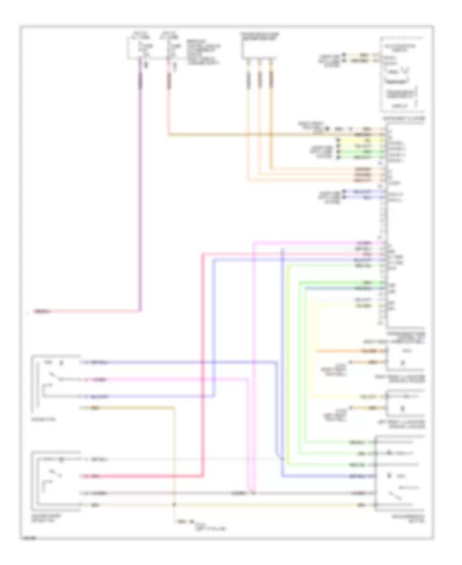 https://portal-diagnostov.com/license.html
Automotive Electricians Portal FZCO
Automotive Electricians Portal FZCO
https://portal-diagnostov.com/license.html
https://portal-diagnostov.com/license.html
Automotive Electricians Portal FZCO
Automotive Electricians Portal FZCOList of elements for Transmission Wiring Diagram (2 of 2) for Mercedes-Benz E250 Bluetec 4Matic 2014:
- (right front footwell) w15/1
- 58d
- Amg button
- Amg esp sport off button
- Amg suspension button
- C15h
- Can b h
- Can b l
- Can c h
- Can c l
- Can e1 h
- Can e1 l
- Can e2 h
- Can e2 l
- Computer data lines system
- Display
- Fuse 15a
- Fuse 5a
- Gear ind
- Hot at all times
- Instrument cluster
- Ism
- Led
- Left front illuminated door sill molding
- Lin b11
- Multi-function display
- Pnk
- Prnd
- Rear sam control module w/ fuse/relay module (right side of luggage compt)
- Right front illuminated door sill molding
- S t amg
- S t esp
- Sig
- Sts
- Transmission mode control unit (right front upper footwell)
- Transmission mode display
- Transmission mode rotary switch
- W13/1 (left "c" pillar)
- W15/1 (right front footwell)
- W15/2 (left front footwell)
TRUNK, TAILGATE, FUEL DOOR
Trunk Pull-Down Wiring Diagram (1 of 2) for Mercedes-Benz E250 Bluetec 4Matic 2014
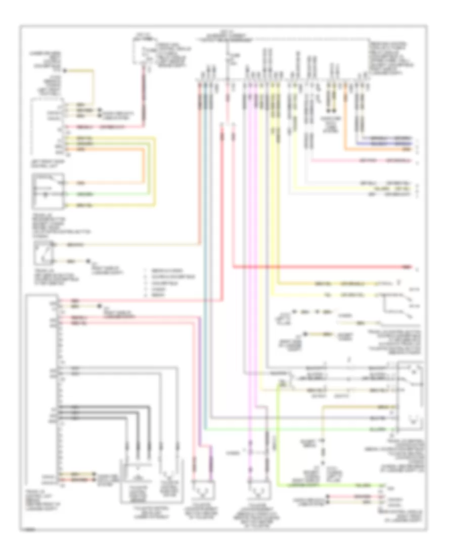 https://portal-diagnostov.com/license.html
Automotive Electricians Portal FZCO
Automotive Electricians Portal FZCO
https://portal-diagnostov.com/license.html
https://portal-diagnostov.com/license.html
Automotive Electricians Portal FZCO
Automotive Electricians Portal FZCOList of elements for Trunk Pull-Down Wiring Diagram (1 of 2) for Mercedes-Benz E250 Bluetec 4Matic 2014:
- (under driver's seat) (coupe & convertible) w18
- 30g
- 58d
- 58d (or sig)
- C12i
- C5h
- C6hd
- C7i
- C9i
- Can b h
- Can b l
- Can b-h
- Can b-l
- Computer data lines system
- Convertible
- Coupe & convertible
- Except sedan
- Except wagon
- Front sam control module w/ fuse & relay module (left rear of engine compt)
- Fuse 30a
- Fuse 40a
- Gnd
- Hot at all times
- Hot w/ quiescent current cutout relay energized
- Left front door control unit
- Nca
- Rear control module (right front of luggage compt)
- Rear sam control module w/ fuse & relay module (convertible: in spare wheel well) (except convertible: right side of luggage compt)
- Red
- Sedan
- Sedan & wagon
- Sig
- Sig (or 58d)
- Sig (or) sig 90
- Tailgate control drive unit (under hatshelf)
- Tailgate control electric motor
- Tailgate control position sensor
- Tailgate locking element (bottom center of tailgate)
- Tailgate locking element (sedan & wagon w/o remote trunk closing) (bottom center of tailgate)
- Trunk lid central locking motor (sedan, coupe & convertible) tailgate central locking motor (wagon) (wagon: center rear of luggage compt lid)
- Trunk lid control button (coupe & convertible w/ keyless go & automatic trunk lid) tailgate control button (sedan & wagon)
- Trunk lid control unit (sedan) (center front of luggage compt)
- Trunk lid keyless go button (coupe & convertible w/ keyless go)
- Trunk lid release button (except wagon) driver trunk lid/liftgate control button (wagon)
- W13/1 (left "c" pillar)
- W13/1 (wagon) (left "c" pillar)
- W15/2 (sedan & wagon) (left front footwell)
- W7 (except wagon) (right side of luggage compt)
- W7 (right side of luggage compt)
- Wagon
- X8/19-c1
- X8/47-c1
- Zv mot
- Zv mot (or hfe)
- Zv mut
Trunk Pull-Down Wiring Diagram (2 of 2) for Mercedes-Benz E250 Bluetec 4Matic 2014
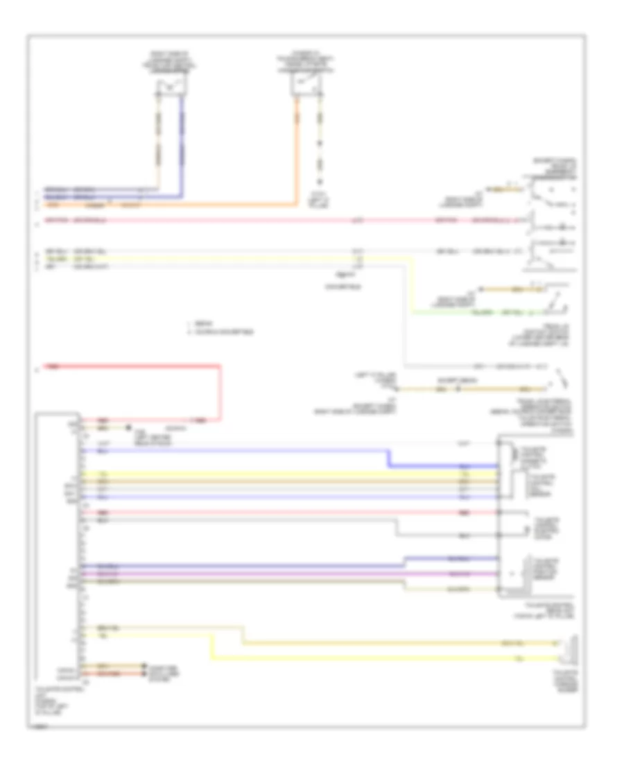 https://portal-diagnostov.com/license.html
Automotive Electricians Portal FZCO
Automotive Electricians Portal FZCO
https://portal-diagnostov.com/license.html
https://portal-diagnostov.com/license.html
Automotive Electricians Portal FZCO
Automotive Electricians Portal FZCOList of elements for Trunk Pull-Down Wiring Diagram (2 of 2) for Mercedes-Benz E250 Bluetec 4Matic 2014:
- (+)
- (-)
- (except wagon) trunk lid emergency opening switch
- (left "c" pillar) (wagon) w13/1
- (right side of luggage compt) trunk cap central locking motor
- (wagon w/ folding bench seat) inside liftgate handle flap switch
- (wagon)
- 30g
- Can b h
- Can b l
- Computer data lines system
- Convertible
- Coupe & convertible
- Except sedan
- Gnd
- Red
- Sedan
- Sig
- Sig 1
- Sig 2
- Tailgate control drive unit (top of left "d" pillar)
- Tailgate control electric motor
- Tailgate control hall sensor
- Tailgate control magnetic clutch
- Tailgate control position sensor
- Tailgate control unit (wagon) (top of left "d" pillar)
- Tailgate control warning buzzer
- Tailgate external operation switch
- Trunk lid contact switch (lower center rear of luggage compt lid)
- Trunk lid external operation switch (sedan, coupe & convertible)
- W13/1 (left "c" pillar)
- W48 (left center rear of roof)
- W7 (except wagon) (right side of luggage compt)
- W7 (right side of luggage compt)
- Wagon
- X8/19-c1
- X8/45-c4
- X8/46-c1
WARNING SYSTEMS
Seat Belt Warning Wiring Diagram for Mercedes-Benz E250 Bluetec 4Matic 2014
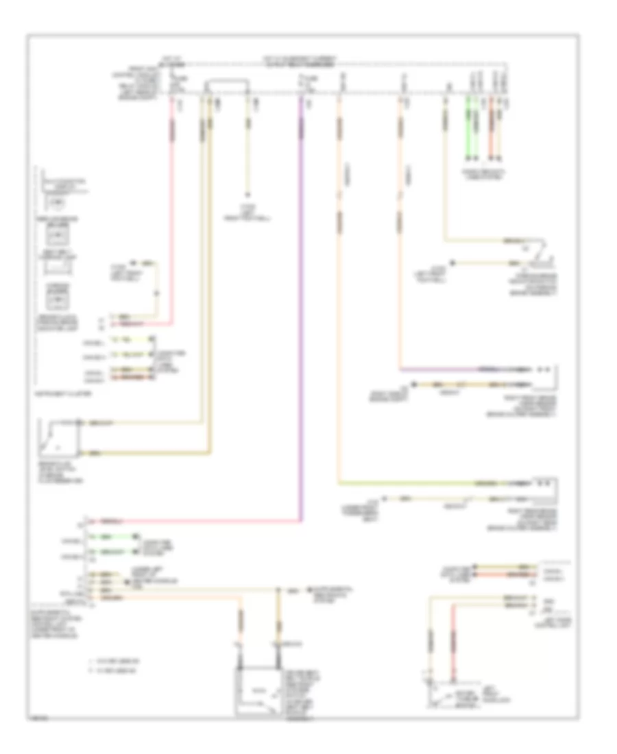 https://portal-diagnostov.com/license.html
Automotive Electricians Portal FZCO
Automotive Electricians Portal FZCO
https://portal-diagnostov.com/license.html
https://portal-diagnostov.com/license.html
Automotive Electricians Portal FZCO
Automotive Electricians Portal FZCOList of elements for Seat Belt Warning Wiring Diagram for Mercedes-Benz E250 Bluetec 4Matic 2014:
- (under left front of center console) w26
- Bbv hr
- Bbv vl
- Bfs
- Brake fluid & parking brake indicator lamp
- Brake fluid level switch (in brake fluid reservoir)
- C11c
- C15m
- C19i
- C20m
- C22i
- C5c
- Can b h
- Can b l
- Can e h
- Can e l
- Can e2 h
- Can e2 l
- Computer data lines system
- Driver seat belt buckle restraint systems switch (in driver seat belt buckle assembly)
- Front sam control module w/ fuse/ relay module (left rear of engine compt)
- Fuse 7.5a
- Gnd
- Gss fa
- Hot at all times
- Hot w/ quiescent current cutout relay energized
- Instrument cluster
- Left door control unit
- Left front door lock
- Multi-function display
- Nca
- Parking brake indicator switch (on parking brake assembly)
- Right front brake wear sensor (on right front brake caliper assembly)
- Right rear brake wear sensor (on right rear brake caliper assembly)
- Rotary tumbler switch
- Rtn line
- Seat belt warning lamp
- Service brake ind lamp
- Sig
- W/ keyless go
- W/o keyless go
- W15/2 (left front footwell)
- W15/5 (left front footwell)
- W19 (under front passenger's seat)
- W2 (right side of engine compt)
- Warning buzzer
- X55/3-c2
- X62/33-c1
- X62/6-c1
Tire Pressure Monitoring Wiring Diagram for Mercedes-Benz E250 Bluetec 4Matic 2014
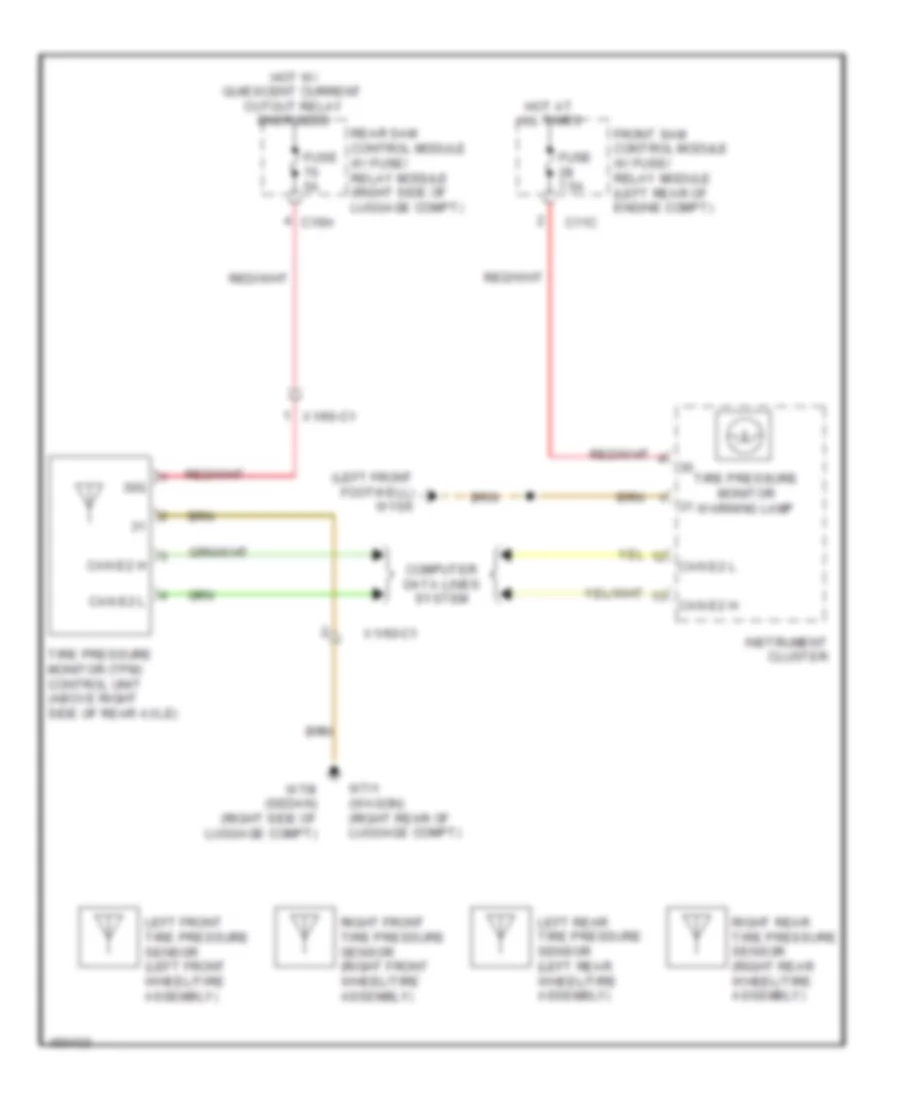 https://portal-diagnostov.com/license.html
Automotive Electricians Portal FZCO
Automotive Electricians Portal FZCO
https://portal-diagnostov.com/license.html
https://portal-diagnostov.com/license.html
Automotive Electricians Portal FZCO
Automotive Electricians Portal FZCOList of elements for Tire Pressure Monitoring Wiring Diagram for Mercedes-Benz E250 Bluetec 4Matic 2014:
- (left front footwell) w15/5
- 30g
- C11c
- C15h
- Can e2 h
- Can e2 l
- Computer data lines system
- Front sam control module w/ fuse/ relay module (left rear of engine compt)
- Fuse 5a
- Fuse 7.5a
- Hot at all times
- Hot w/ quiescent current cutout relay energized
- Instrument cluster
- Left front tire pressure sensor (left front wheel/tire assembly)
- Left rear tire pressure sensor (left rear wheel/tire assembly)
- Rear sam control module w/ fuse/ relay module (right side of luggage compt)
- Right front tire pressure sensor (right front wheel/tire assembly)
- Right rear tire pressure sensor (right rear wheel/tire assembly)
- Tire pressure monitor (tpm) control unit (above right side of rear axle)
- Tire pressure monitor warning lamp
- W7/1 (wagon) (right rear of luggage compt)
- W7/8 (sedan) (right side of luggage compt)
- X1/60-c1
WIPER/WASHER
Headlamp Washer Wiring Diagram for Mercedes-Benz E250 Bluetec 4Matic 2014
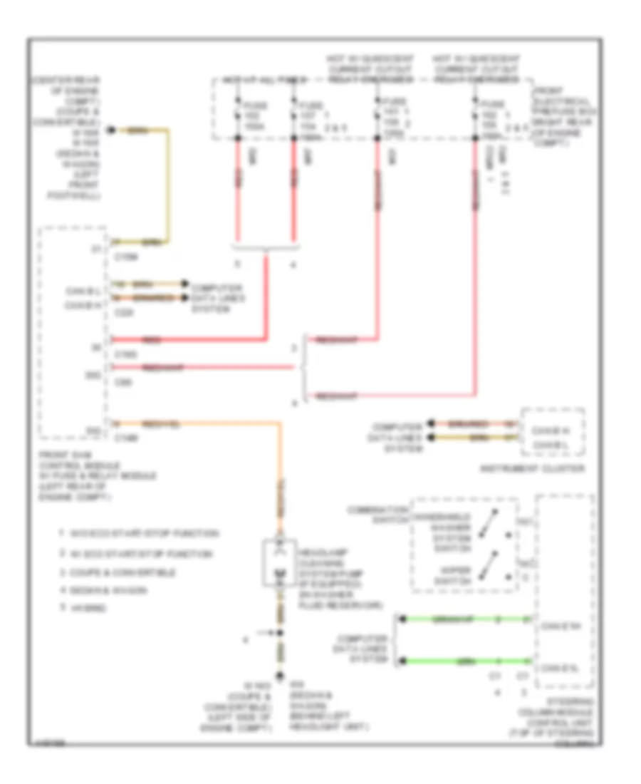 https://portal-diagnostov.com/license.html
Automotive Electricians Portal FZCO
Automotive Electricians Portal FZCO
https://portal-diagnostov.com/license.html
https://portal-diagnostov.com/license.html
Automotive Electricians Portal FZCO
Automotive Electricians Portal FZCOList of elements for Headlamp Washer Wiring Diagram for Mercedes-Benz E250 Bluetec 4Matic 2014:
- (center rear of engine compt) (coupe & convertible) w16/6 w15/5 (sedan & wagon) (left front footwell)
- 30g
- C14m
- C15m
- C16s
- C22i
- C8s
- Can b h
- Can b l
- Can e1h
- Can e1l
- Combination switch
- Computer data lines system
- Coupe & convertible
- Front electrical prefuse box (right rear of engine compt)
- Front sam control module w/ fuse & relay module (left rear of engine compt)
- Fuse 100a
- Fuse 150a
- Headlamp cleaning system pump (if equipped) (in washer fluid reservoir)
- Hot at all times
- Hot w/ quiescent current cutout relay energized
- Hybrid
- Instrument cluster
- Mg1
- Mr2
- Mr7
- Mrg2
- Red
- Sedan & wagon
- Sig
- Steering column module control unit (top of steering column)
- W/ eco start/stop function
- W/o eco start/stop function
- W16/3 (coupe & convertible) (left side of engine compt)
- W9 (sedan & wagon) (behind left headlight unit)
- Windshield washer system switch
- Wiper switch
Wiper/Washer Wiring Diagram for Mercedes-Benz E250 Bluetec 4Matic 2014
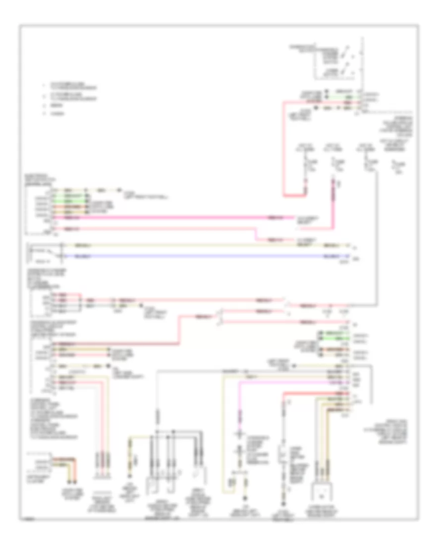 https://portal-diagnostov.com/license.html
Automotive Electricians Portal FZCO
Automotive Electricians Portal FZCO
https://portal-diagnostov.com/license.html
https://portal-diagnostov.com/license.html
Automotive Electricians Portal FZCO
Automotive Electricians Portal FZCOList of elements for Wiper/Washer Wiring Diagram for Mercedes-Benz E250 Bluetec 4Matic 2014:
- (+)
- (left front footwell)
- 30g
- 30z
- C13d
- C14m
- C19i
- C1m
- C21m
- C22i
- C5c
- Can b h
- Can b l
- Can e h
- Can e l
- Combination switch
- Computer data lines system
- Electronic ignition switch control unit
- Front sam control module w/ fuse/relay module circuit 30 fuse (left rear of engine compt)
- Fuse 30a
- Fuse 7.5a
- Gnd
- Hot at all times
- Hot w/ circuit 15r relay energized
- Instrument cluster
- Lin 2
- Nca
- Overhead control panel control unit (w/ power glass tilting/sliding sunroof) overhead control panel electronics (w/o power glass tilting/sliding sunroof)
- Panoramic sliding roof control module (if equipped) (center front of roof)
- Rain/light sensor (top center of windshield)
- Red
- Sedan
- Sig
- Spray nozzle heater (if equipped) (rear of engine compt lid)
- Spray nozzle hose heater (if equipped) (rear of engine compt lid)
- Steering column module control unit (top of steering column)
- W/ direct select
- W/ power glass tilting/sliding sunroof
- W/o direct select
- W/o power glass tilting/sliding sunroof
- W15/2 (left front footwell)
- W15/5
- W15/5 (left front footwell)
- W6 (left side luggage compt)
- W9 (behind left headlight unit)
- Wagon
- Windshield washer system fluid level switch (in washer fluid reservoir)
- Windshield washer system pump (in washer fluid reservoir)
- Windshield washer system switch
- Wiper motor (center rear of engine compt)
- Wiper park heater (if equipped) (center rear of engine compt)
- Wiper switch
- X18/37-c1
- X204
- X88/11

 Čeština
 Dansk
Dansk Deutsch
 Ελληνικά
 English
 English
 Español
 Suomi
Suomi Français
 Français
 עברית
עברית Hrvatski
 Magyar
 Italiano
 日本語
日本語 한국어
한국어 Nederlands
 Polski
 Português
 Português
 Română
 Русский
 Slovenčina
 Slovenščina
 Svenska
 中文 (中国)
