AIR CONDITIONING
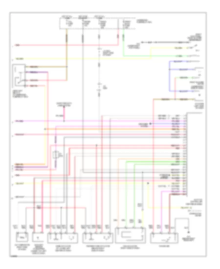
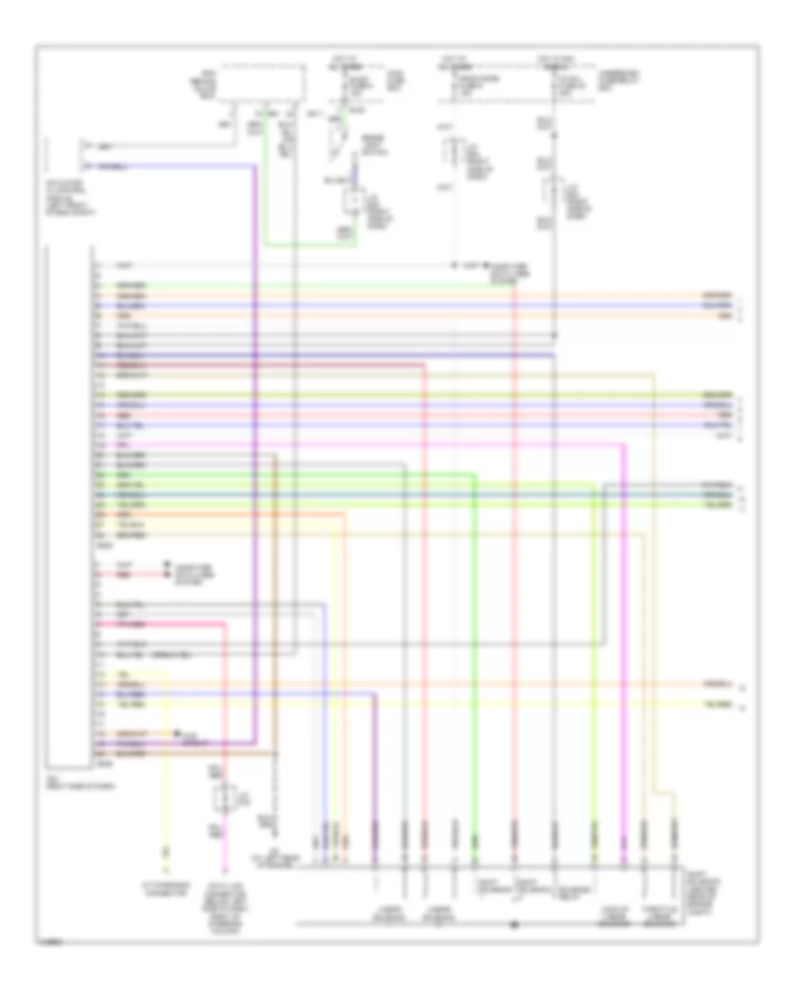
Automatic A/C Wiring Diagram (1 of 2) for Suzuki XL-7 LX 2005
 https://portal-diagnostov.com/license.html
Automotive Electricians Portal FZCO
Automotive Electricians Portal FZCO
https://portal-diagnostov.com/license.html
https://portal-diagnostov.com/license.html
Automotive Electricians Portal FZCO
Automotive Electricians Portal FZCO
List of elements for Automatic A/C Wiring Diagram (1 of 2) for Suzuki XL-7 LX 2005:
- (left side of dash) j/c (e45)
- (right side of dash) j/c (c71)
- A/c compressor
- A/c compressor relay (in underhood fuse/relay box)
- A/c condenser fan high relay 1 (in underhood fuse/relay box)
- A/c condenser fan high relay 2 (in underhood fuse/relay box)
- A/c fuse 25a
- Body control module (behind center of dash)
- C51-3
- Condenser fan motor (right front of engine compartment)
- Condenser relay (in underhood fuse/relay box)
- E120
- E121
- E61
- Ecm (behind glove box)
- Ect sensor (top front of engine)
- G10 (under right kick panel)
- G53
- G54
- G55
- G57
- G7 (behind left headlight)
- G8 (behind right headlight)
- Heater fuse 15a
- Hot at all times
- Hot in on start
- Htr fuse 60a
- Main fuse box
- Outdoor sensor (at right front of engine compartment)
- Pnk
- Red
- Triple pressure switch (at right front of engine compartment)
- Underdash fuse/relay box
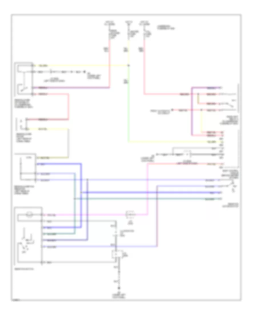
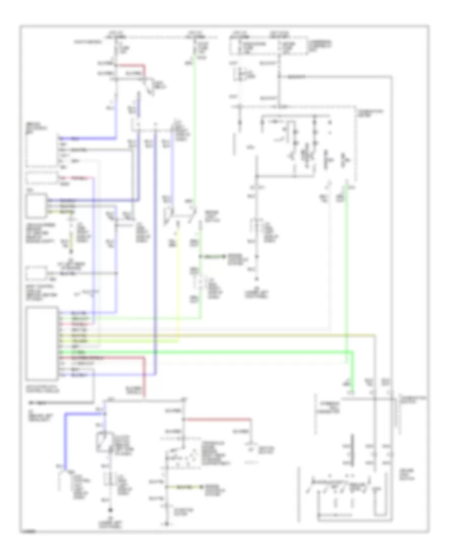
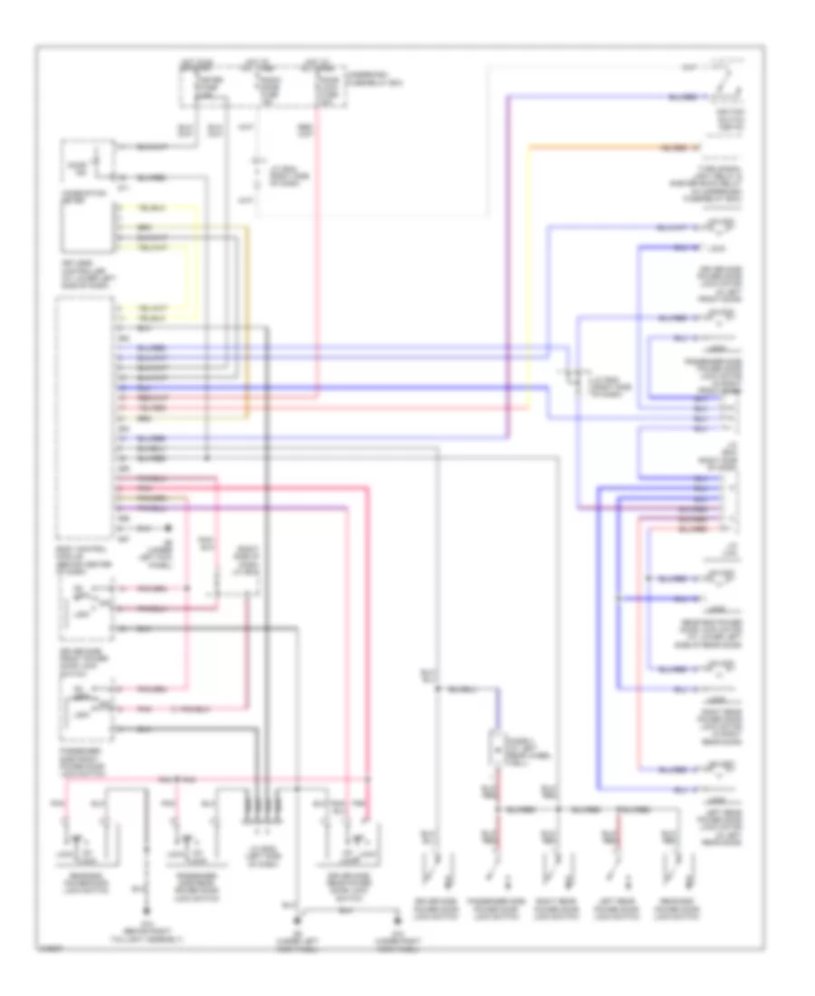
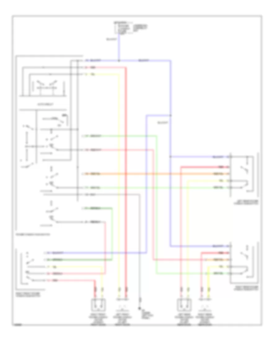
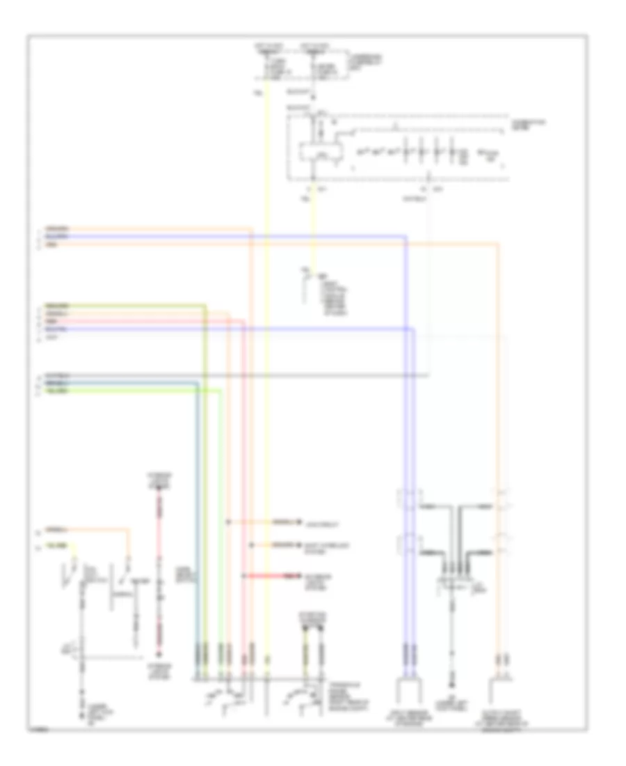
Automatic A/C Wiring Diagram (2 of 2) for Suzuki XL-7 LX 2005
 https://portal-diagnostov.com/license.html
Automotive Electricians Portal FZCO
Automotive Electricians Portal FZCO
https://portal-diagnostov.com/license.html
https://portal-diagnostov.com/license.html
Automotive Electricians Portal FZCO
Automotive Electricians Portal FZCOList of elements for Automatic A/C Wiring Diagram (2 of 2) for Suzuki XL-7 LX 2005:
- (at lower left
- (behind right
- (center of dash)
- (right kick panel) front blower motor relay
- (right side
- (under right side of dash)
- (under top left
- A/c diode (left side of dash)
- A/c thermistor
- Auto a/c controller
- Center of dash)
- Combination meter
- Computer data lines system
- Defogger system
- Fan actuator (right side of dash)
- Fan driver
- Front blow fuse 40a
- Front blower motor
- G10 (under right kick panel)
- G11
- G14 (behind right headlight)
- Headlight relay 2 (in underdash fuse/relay box)
- Hot at all times
- Hot in on or start
- Interior lights system
- J/c (e44) (right side of dash)
- J/c (g16)
- J/c (g29)
- Meter fuse 10a
- Mode actuator
- Of dash)
- Pnk
- Radio/ dome fuse 15a
- Red
- Side of dash)
- Sunlight sensor (if equipped)
- Tail fuse 10a
- Temperature actuator
- Underdash fuse/relay box
Rear A/C Wiring Diagram for Suzuki XL-7 LX 2005
 https://portal-diagnostov.com/license.html
Automotive Electricians Portal FZCO
Automotive Electricians Portal FZCO
https://portal-diagnostov.com/license.html
https://portal-diagnostov.com/license.html
Automotive Electricians Portal FZCO
Automotive Electricians Portal FZCOList of elements for Rear A/C Wiring Diagram for Suzuki XL-7 LX 2005:
- Body control module (behind center of dash)
- Front automatic a/c circuit
- G53
- G54
- G55
- G57
- G9 (under left kick panel)
- Headlight relay 2 (in underdash fuse/relay box)
- Heater fuse 15a
- Hot at all times
- Hot in on
- Illumination j/c (g44)
- J/c (e45) (left side of dash)
- J/c (g16)
- J/c (g35)
- Off
- Rear blower fan resistor (left rear of cargo area)
- Rear blower fuse 20a
- Rear blower motor (left rear of cargo area)
- Rear blower motor relay (in underdash fuse/relay box)
- Rear fan motor switch
- Rear fan switch
- Tail fuse 10a
- Underdash fuse/relay box
ANTI-LOCK BRAKES
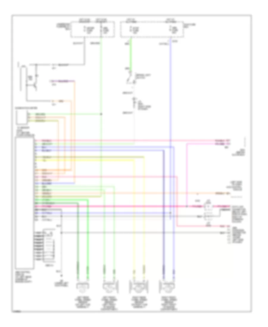
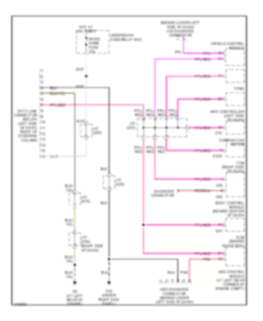
Anti-lock Brakes Wiring Diagram for Suzuki XL-7 LX 2005
 https://portal-diagnostov.com/license.html
Automotive Electricians Portal FZCO
Automotive Electricians Portal FZCO
https://portal-diagnostov.com/license.html
https://portal-diagnostov.com/license.html
Automotive Electricians Portal FZCO
Automotive Electricians Portal FZCOList of elements for Anti-lock Brakes Wiring Diagram for Suzuki XL-7 LX 2005:
- (left side of dash) 4wd control module
- 4wd
- Abs control module (at left rear corner of engine compt)
- Abs diagnosis connector (behind lower left side of dash)
- Abs fuse 10a
- Abs fuse 60a
- Abs hu
- Abs ind
- Brake light switch
- Combination meter
- Cpu
- Data link connector (below left side of dash, right of steering column)
- E120
- E61
- Ecm (behind glove box)
- G10
- G11
- G9 (under left kick panel)
- Hot at all times
- Hot in on or start
- J/c (e42) (right side of dash)
- J/c (g16)
- J/c (g35)
- Left front wheel speed sensor (left front of engine compartment)
- Left rear wheel speed sensor (on left hub assembly)
- Main fuse box
- Meter fuse 10a
- Nca
- Pnk
- Right front wheel speed sensor (right front of engine compartment)
- Right rear wheel speed sensor (on right hub assembly)
- Stop fuse 15a
- Underdash fuse/relay box
- ``g" sensor (4wd) (at center floor console)
BODY CONTROL MODULES
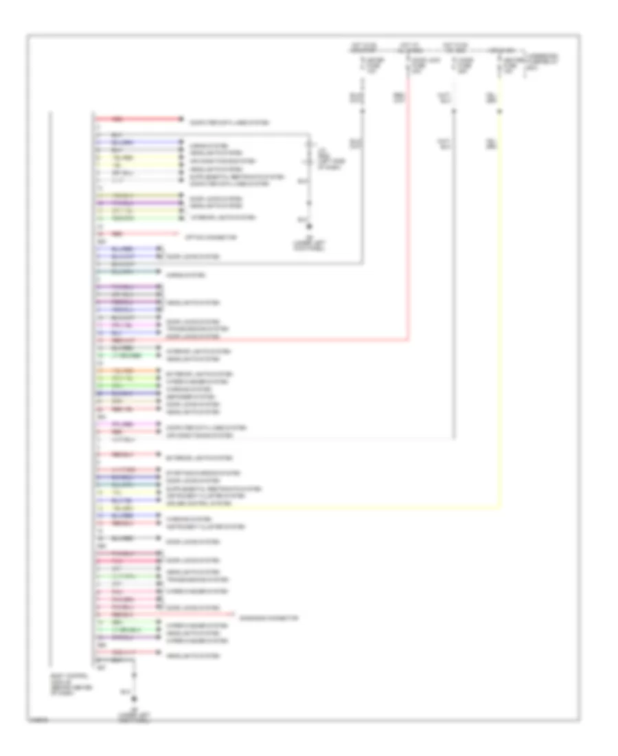
Body Control Modules Wiring Diagram for Suzuki XL-7 LX 2005
 https://portal-diagnostov.com/license.html
Automotive Electricians Portal FZCO
Automotive Electricians Portal FZCO
https://portal-diagnostov.com/license.html
https://portal-diagnostov.com/license.html
Automotive Electricians Portal FZCO
Automotive Electricians Portal FZCOList of elements for Body Control Modules Wiring Diagram for Suzuki XL-7 LX 2005:
- Air conditioning system
- Body control module (behind center of dash)
- Cigar fuse 25a
- Computer data lines system
- Cruise control system
- Defogger system
- Diagnosis connector
- Door lock fuse 20a
- Door locks system
- Exterior lights system
- G53
- G54
- G55
- G56
- G57
- G9 (under left kick panel)
- Headlights system
- Heater fuse 15a
- Horns system
- Hot at all times
- Hot in on
- Hot in on or acc
- Hot in on or start
- Instrument cluster system
- Interior lights system
- J/c (e45) (left side of dash)
- Meter fuse 10a
- Option connector
- Pnk
- Red
- Starting/charging system
- Transmissions system
- Underdash fuse/relay box
- Warning system
- Wiper/washer system
COMPUTER DATA LINES
Computer Data Lines Wiring Diagram for Suzuki XL-7 LX 2005
 https://portal-diagnostov.com/license.html
Automotive Electricians Portal FZCO
Automotive Electricians Portal FZCO
https://portal-diagnostov.com/license.html
https://portal-diagnostov.com/license.html
Automotive Electricians Portal FZCO
Automotive Electricians Portal FZCOList of elements for Computer Data Lines Wiring Diagram for Suzuki XL-7 LX 2005:
- (behind lower left side of dash) a/b diagnosis connector
- (below left side of dash,
- 4wd controller (left side of dash)
- Abs control module (at left rear corner of engine compt)
- Abs diagnosis connector (behind lower left side of dash)
- Air bag control module
- Body control module (behind center of dash)
- Combination meter
- Data link connector
- Diagnosis connector
- E229
- E61
- Ecm (behind glove box)
- G10
- G10 (under right kick panel)
- G5 (at left rear of engine)
- G55
- G56
- Hot at all times
- J/c (c66) (right side of dash)
- J/c (g15)
- J/c (g16)
- J/c (g29)
- J/c (g35)
- Pnk
- Radio dome fuse 15a
- Right of steering column)
- Tcm (right side of dash)
- Tpms
- Underdash fuse/relay box
CRUISE CONTROL
Cruise Control Wiring Diagram for Suzuki XL-7 LX 2005
 https://portal-diagnostov.com/license.html
Automotive Electricians Portal FZCO
Automotive Electricians Portal FZCO
https://portal-diagnostov.com/license.html
https://portal-diagnostov.com/license.html
Automotive Electricians Portal FZCO
Automotive Electricians Portal FZCOList of elements for Cruise Control Wiring Diagram for Suzuki XL-7 LX 2005:
- (behind glove box) ecm
- 4wd control unit (left side of dash)
- A/t
- Actuator with control module
- Body control module (behind center of dash)
- Brake- light switch
- C51-1
- Cancel
- Clutch switch (behind left side of dash)
- Coast/ set
- Combination meter
- Combination switch
- Cpu
- Cruise ind
- Cruise main switch
- E120
- E229
- E23
- E61
- Engine controls system
- Fi fuse 15a
- G10
- G11
- G3 (at left rear of engine)
- G55
- G7 (behind left headlight)
- G9 (under left kick panel)
- Hot at all times
- Hot in on or start
- Ignition switch
- Illum (if equipped)
- J/c (c66) (right side of dash)
- J/c (c69) (right side of dash)
- J/c (e41) (right side of dash)
- J/c (e42) (right side of dash)
- J/c (e45) (left side of dash)
- J/c (g29)
- J/c (g35) (left side of dash)
- M/t
- Main
- Main fuse box
- Main relay
- Meter fuse 10a
- Nca
- Radio/dome fuse 15a
- Resume/ accel
- Set ind
- Starting motor
- Steering roll connector
- Stop fuse 15a
- Tcm
- Transaxle range sensor (right rear of engine compartment)
- Underdash fuse/relay box
- Vehicle speed sensor (at center rear of engine compt)
DEFOGGERS
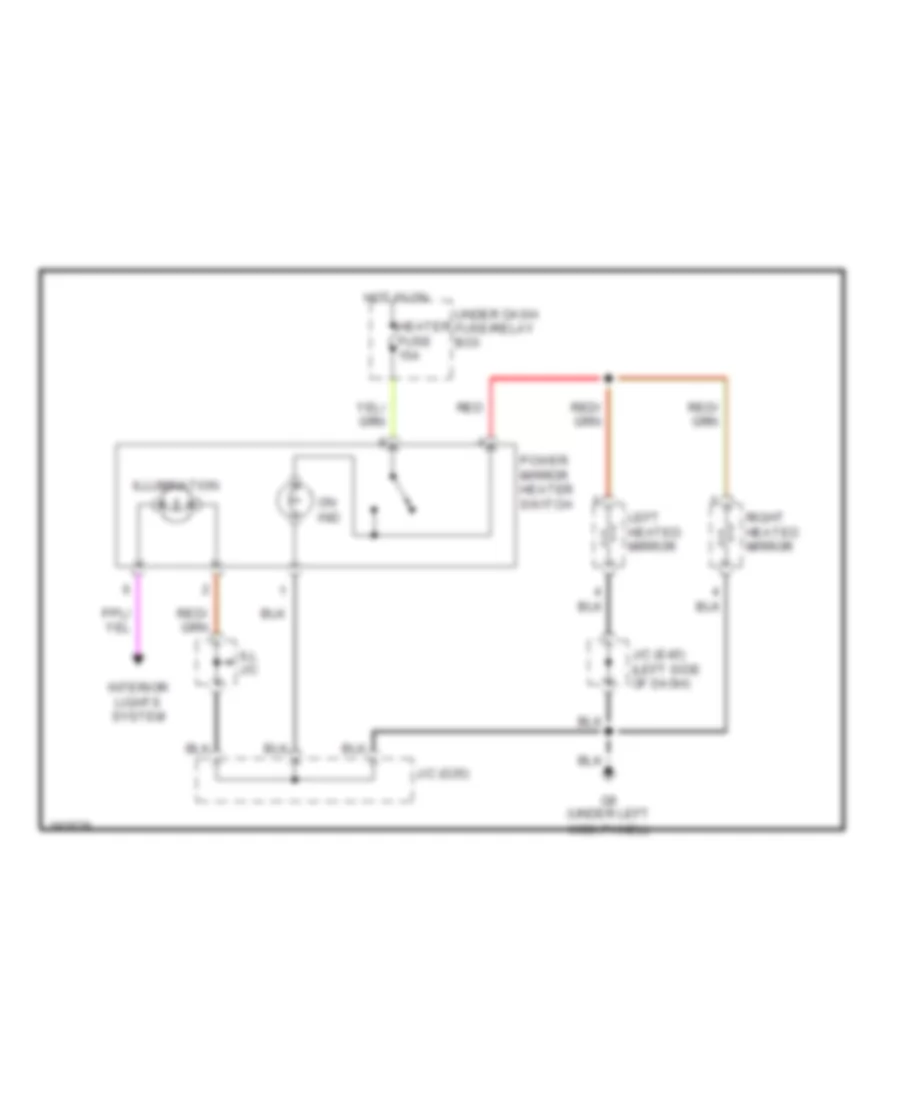
Heated Mirrors Wiring Diagram for Suzuki XL-7 LX 2005
 https://portal-diagnostov.com/license.html
Automotive Electricians Portal FZCO
Automotive Electricians Portal FZCO
https://portal-diagnostov.com/license.html
https://portal-diagnostov.com/license.html
Automotive Electricians Portal FZCO
Automotive Electricians Portal FZCOList of elements for Heated Mirrors Wiring Diagram for Suzuki XL-7 LX 2005:
- G9 (under left kick panel)
- Heater fuse 15a
- Hot in on
- Ill j/c
- Illumination
- Interior lights system
- J/c (e45) (left side of dash)
- J/c (g35)
- Left heated mirror
- On ind
- Power mirror heater switch
- Red
- Right heated mirror
- Under dash fuse/relay box
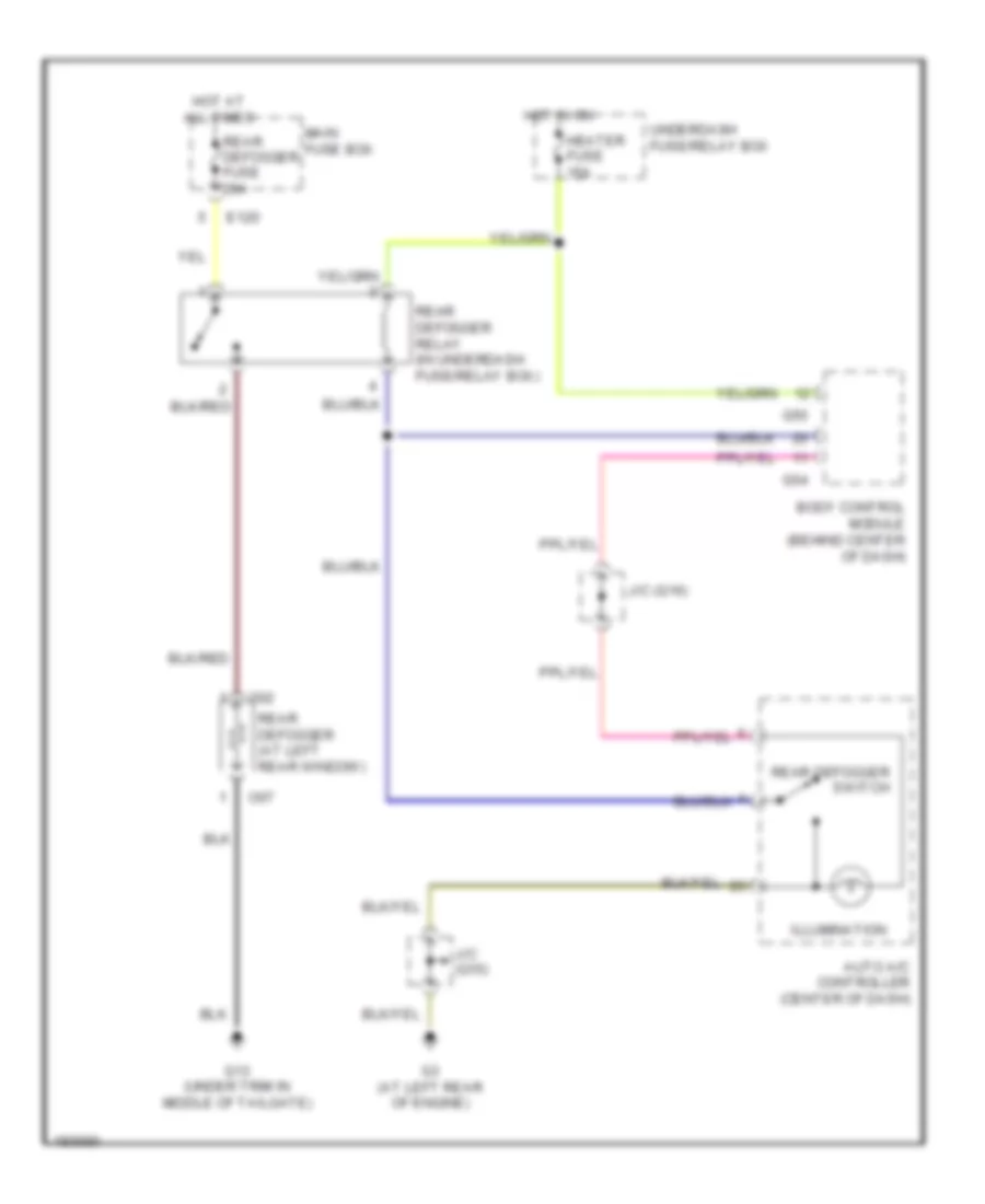
Rear Defogger Wiring Diagram for Suzuki XL-7 LX 2005
 https://portal-diagnostov.com/license.html
Automotive Electricians Portal FZCO
Automotive Electricians Portal FZCO
https://portal-diagnostov.com/license.html
https://portal-diagnostov.com/license.html
Automotive Electricians Portal FZCO
Automotive Electricians Portal FZCOList of elements for Rear Defogger Wiring Diagram for Suzuki XL-7 LX 2005:
- Auto a/c controller (center of dash)
- Body control module (behind center of dash)
- E120
- G13 (under trim in middle of tailgate)
- G3 (at left rear of engine)
- G54
- G55
- Heater fuse 15a
- Hot at all times
- Hot in on
- Illumination
- J/c (g15)
- J/c (g16)
- Main fuse box
- O02
- O07
- Rear defogger (at left rear window)
- Rear defogger fuse 25a
- Rear defogger relay (in underdash fuse/relay box)
- Rear defogger switch
- Underdash fuse/relay box
ENGINE PERFORMANCE
2.7L
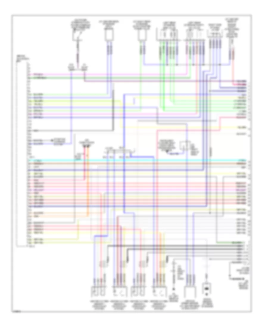
2.7L, Engine Performance Wiring Diagram (1 of 3) for Suzuki XL-7 LX 2005
 https://portal-diagnostov.com/license.html
Automotive Electricians Portal FZCO
Automotive Electricians Portal FZCO
https://portal-diagnostov.com/license.html
https://portal-diagnostov.com/license.html
Automotive Electricians Portal FZCO
Automotive Electricians Portal FZCOList of elements for 2.7L, Engine Performance Wiring Diagram (1 of 3) for Suzuki XL-7 LX 2005:
- (at center rear of
- (at center rear of engine) input sensor
- (at right rear of engine) evap canister purge valve
- (behind glove box) ecm
- (left rear of engine compt) iac valve
- (left rear of engine) egr valve
- (on power steering pump)
- (right side of dash) j/c c69
- Air conditioning system
- C51-1
- C51-3
- Engine compt) (if equipped) evap canister air valve
- G3 (at left rear of engine)
- G5 (at left rear of engine)
- Heated oxygen sensor 1 (on exhaust system)
- Heated oxygen sensor 2 (on exhaust system)
- Heated oxygen sensor 3 (on exhaust system)
- Heated oxygen sensor 4 (on exhaust system)
- Instrument cluster, body computer & transmissions systems
- J/c c66 (right side of dash)
- J/c c66 (right side of dash)
- J/c c67
- J/c c69 (right side of dash)
- Knock sensor (at rear of engine)
- Nca
- Pnk
- Power steering pump pressure switch
- Red
- Starting/ charging system
- Vehicle speed sensor (at center rear of eng compt)
- W/ evap leak
- W/o evap leak
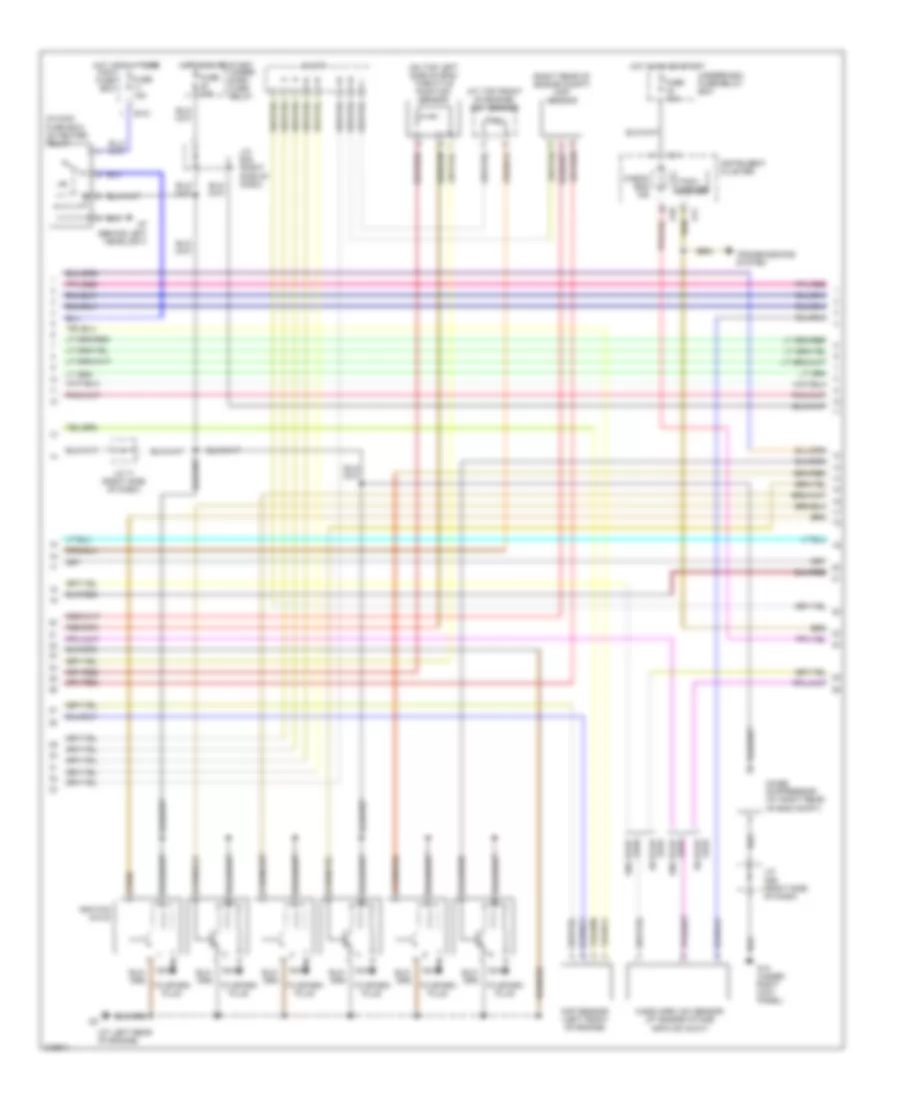
2.7L, Engine Performance Wiring Diagram (2 of 3) for Suzuki XL-7 LX 2005
 https://portal-diagnostov.com/license.html
Automotive Electricians Portal FZCO
Automotive Electricians Portal FZCO
https://portal-diagnostov.com/license.html
https://portal-diagnostov.com/license.html
Automotive Electricians Portal FZCO
Automotive Electricians Portal FZCOList of elements for 2.7L, Engine Performance Wiring Diagram (2 of 3) for Suzuki XL-7 LX 2005:
- (at left rear of engine)
- (at top front of engine) ect sensor
- (behind left headlight)
- (in main fuse box) o2 heater relay
- (on top left side of eng) throttle position sensor
- (right rear of engine compt) map sensor
- Check eng ind
- Cmp sensor (left front of engine)
- E121
- Fuse 10a
- Fuse 15a
- Fuse 20a
- G10
- G10 (under right kick panel)
- G11
- Hot at all times
- Hot in on or start
- Ignition coils
- Instrument cluster
- J/c 71 (right side of dash)
- J/c c69 (right side of dash)
- J/c c71
- J/c e43 (right side of dash)
- Main fuse box
- Mass air-flow sensor (at engine intake air-flow duct)
- Nca
- Noise suppressor (at right rear of eng compt)
- Tach- ometer
- To spark plug
- Transmissions system
- Under- dash fuse/ relay
- Underdash fuse/relay box
- W/ evap leak
- W/o evap leak
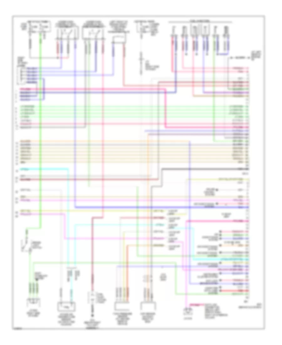
2.7L, Engine Performance Wiring Diagram (3 of 3) for Suzuki XL-7 LX 2005
 https://portal-diagnostov.com/license.html
Automotive Electricians Portal FZCO
Automotive Electricians Portal FZCO
https://portal-diagnostov.com/license.html
https://portal-diagnostov.com/license.html
Automotive Electricians Portal FZCO
Automotive Electricians Portal FZCOList of elements for 2.7L, Engine Performance Wiring Diagram (3 of 3) for Suzuki XL-7 LX 2005:
- (at left rear of engine) g5
- (left front of engine compt) (if equipped) variable inhalation valve
- (right side of dash) j/c e41
- (under dash fuse/relay box) fuel pump relay
- (under dash fuse/relay box) main relay
- Air conditioning system
- Anti-lock brake system
- Brake- light switch
- C51-2
- Ckp sensor (on right front of eng)
- Computer data lines system
- Connector (below left side of dash, right of steering column)
- Cruise control system
- Data link
- E120
- E61
- Ecm (behind glove box)
- Fuel injectors
- Fuel pump (in fuel tank)
- Fuse 15a
- Fuse 25a
- G12 (behind right taillight assembly)
- Hot at all times
- Instrument cluster system
- Intake air temperature sensor (on air filter housing)
- J/c e42 (right side of dash)
- J/c e44 (right side of dash)
- J/c g16
- Leak w/ evap
- Main fuse box
- Nca
- Pnk
- Red
- Shift interlock system
- Tank pressure sensor (at center rear of vehicle)
- Under- dash fuse/ relay box
- W evap leak
- W/ evap leak
- W/o evap leak
EXTERIOR LIGHTS
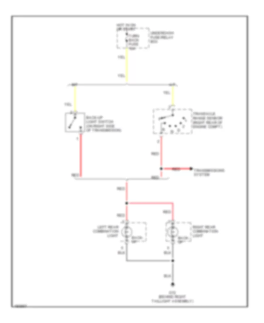
Back-up Lamps Wiring Diagram for Suzuki XL-7 LX 2005
 https://portal-diagnostov.com/license.html
Automotive Electricians Portal FZCO
Automotive Electricians Portal FZCO
https://portal-diagnostov.com/license.html
https://portal-diagnostov.com/license.html
Automotive Electricians Portal FZCO
Automotive Electricians Portal FZCOList of elements for Back-up Lamps Wiring Diagram for Suzuki XL-7 LX 2005:
- A/t
- Back- up
- Back-up light switch (on right side of transmission)
- G12 (behind right taillight assembly)
- Hot in on or start
- Left rear combination light
- M/t
- Red
- Right rear combination light
- Transaxle range sensor (right rear of engine compt)
- Transmissions system
- Turn back fuse 10a
- Underdash fuse/relay box
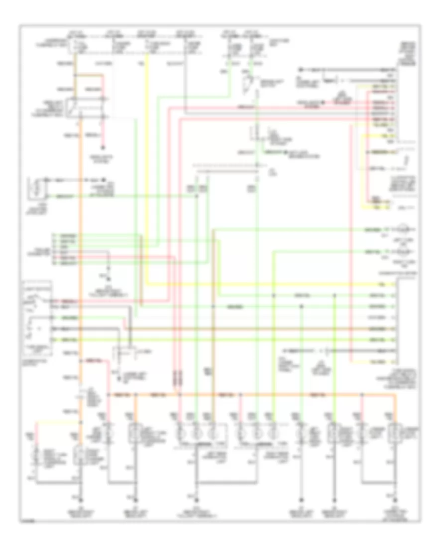
Exterior Lamps Wiring Diagram for Suzuki XL-7 LX 2005
 https://portal-diagnostov.com/license.html
Automotive Electricians Portal FZCO
Automotive Electricians Portal FZCO
https://portal-diagnostov.com/license.html
https://portal-diagnostov.com/license.html
Automotive Electricians Portal FZCO
Automotive Electricians Portal FZCOList of elements for Exterior Lamps Wiring Diagram for Suzuki XL-7 LX 2005:
- (behind center of dash) body control module
- (under left kick panel) g9
- Anti-lock brakes system
- Brake
- Brakelight switch
- Combination meter
- Combination switch
- Cpu
- E120
- E121
- G10
- G10 (under right kick panel)
- G11
- G12 (behind right taillight assembly)
- G13 (under trim in middle of tailgate)
- G53
- G54
- G55
- G57
- G7 (behind left headlight)
- G8 (behind right headlight)
- G9 (under left kick panel)
- Hazard fuse 10a
- Head
- Headlight relay 2 (in underdash fuse/relay box)
- Headlights
- Headlights system
- High mounted stoplight
- Horn fuse 15a
- Hot at all times
- Hot in on or start
- Illumination controller (behind left side of dash)
- J/c (e42) (right side of dash)
- J/c (e44) (right side of dash)
- J/c (e45) (left side of dash)
- J/c (g35)
- J/c (l04)
- Left front turn signal & clearance light
- Left front turn signal light
- Left rear combination light
- Left side marker light
- Left turn ind
- License plate light 1
- License plate light 2
- Light switch
- Main fuse box
- Meter fuse 10a
- Off
- Right front turn signal & clearance light
- Right front turn signal light
- Right rear combination light
- Right side marker light
- Right turn ind
- Stop fuse 15a
- System
- Tail
- Tail fuse 10a
- Trailer connector
- Turn
- Turn back fuse 10a
- Turn signal light
- Turn signal light relay & answer back relay (in underdash fuse/relay box)
- Underdash fuse/relay box
GROUND DISTRIBUTION
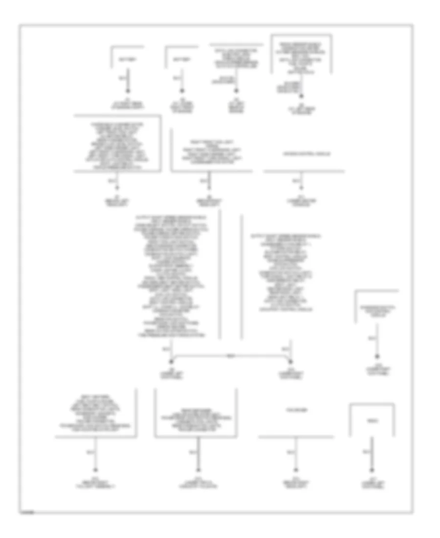
Ground Distribution Wiring Diagram for Suzuki XL-7 LX 2005
 https://portal-diagnostov.com/license.html
Automotive Electricians Portal FZCO
Automotive Electricians Portal FZCO
https://portal-diagnostov.com/license.html
https://portal-diagnostov.com/license.html
Automotive Electricians Portal FZCO
Automotive Electricians Portal FZCOList of elements for Ground Distribution Wiring Diagram for Suzuki XL-7 LX 2005:
- Air bag control module
- Battery
- Data link connector, electric leak check module, vehicle speed sensor, auto a/c controller
- Diagnosis switch, 4wd control module
- Fan driver
- G1 (at right rear of engine compt)
- G10 (under right kick panel)
- G11 (under center console)
- G12 (behind right taillight assembly)
- G13 (under trim in middle of tailgate)
- G14 (behind right headlight)
- G15 (under right kick panel)
- G17 (under left kick panel)
- G2 (at lower right front of engine)
- G3 (at left rear of engine)
- G5 (at left rear of engine)
- G7 (behind left headlight)
- G8 (behind right headlight)
- G9 (under left kick panel)
- Knock sensor shield, combination meter, oxygen sensors shields, ecm, tcm, data link connector, fuel pump & gauge, ignition coils
- Output shaft speed sensor shield, input sensor shield, condenser hi fan relay 1, t/f fork switch, blower motor relay, body control module, noise suppressor, 4wd switch, 4wd low switch, combination switch (light), turn signal light relay & answerback relay, spot light, center room light, rear room light, headlight relay 1, data link connector, clutch switch, occupant control module
- Output shaft speed sensor shield, input sensor shield, mode select switch, o/d cut switch, power mirrors, power mirror switch, power mirror heater switch, power window main switch, front fog light switch, abs diagnosis connector, combination switch (wiper), combination switch (light), shift lock solenoid, hazard switch, sliding roof assembly, cigar lighter, clock, clutch switch, radio, abs control module, driver's seat heater switch, passenger's seat heater switch, spot light, room light, 4wd low switch, data link connector, body control module, shift ill, cigar ill, acc relay, combination meter, 4wd switch, rear fan switch, power door lock switches, mirror heater, rear a/c fan motor switch, tire pressure monitoring system
- Radio
- Rear defogger, high mounted stoplight, power door lock switch (rear end), license plate lights, rear combination lights, trailer connector
- Right front fog light, horns, right front clearance light, right side marker light, right front turn signal light, condenser fan motor
- Seat heaters, fuel pump & gauge, left seat belt switch, rear combination lights, accessory sockets, sub woofer, trailer connector, power door lock switch (rear end), high mounted stoplight
- Windshield washer motor, washer level switch, left front fog light, o2 heater relay, rear washer motor, brake fluid level switch, left side marker light, left front clearance light, left front turn signal light, actuator with control module, shift lock relay, triple pressure switch
HEADLIGHTS
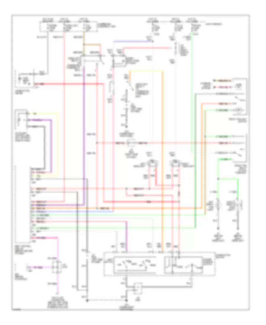
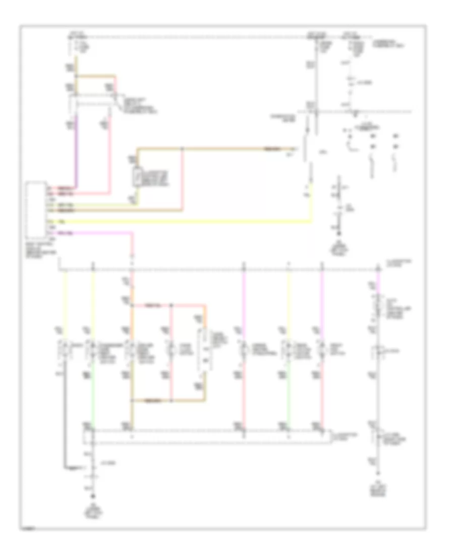
Headlights Wiring Diagram for Suzuki XL-7 LX 2005
 https://portal-diagnostov.com/license.html
Automotive Electricians Portal FZCO
Automotive Electricians Portal FZCO
https://portal-diagnostov.com/license.html
https://portal-diagnostov.com/license.html
Automotive Electricians Portal FZCO
Automotive Electricians Portal FZCOList of elements for Headlights Wiring Diagram for Suzuki XL-7 LX 2005:
- Autolight controller (on top right side of dash)
- Body control module (behind center of dash)
- Combination meter
- Combination switch
- Data link connector (below left side of dash, right of steering column)
- Dimmer/ passing switch
- Diode 1 (right side of dash)
- Door lock fuse 20a
- E120
- E121
- E61
- Ecm (behind glove box)
- Fr fog fuse 15a
- Front fog relay (in main fuse box)
- Front foglight switch
- G10 (under right kick panel)
- G11
- G53
- G54
- G55
- G56
- G57
- G7 (behind left headlight)
- G8 (behind right headlight)
- H/l l fuse 15a
- H/l r fuse 15a
- Head
- Headlight relay 1 (in underdash fuse/relay box)
- Headlight relay 2 (in underdash fuse/relay box)
- High beam ind
- Hot at all times
- Hot in on or start
- Illum
- Interior lights system
- J/c (e41) (right side of dash)
- J/c (e44) (right side of dash)
- J/c (e45) (left side of dash)
- J/c (g16)
- J/c (g35)
- Left front fog light
- Left headlight
- Light switch
- Main fuse box
- Meter fuse 10a
- Off
- Pass
- Red
- Right front fog light
- Right headlight
- Tail
- Tail fuse 10a
- Underdash fuse/relay box
HORN
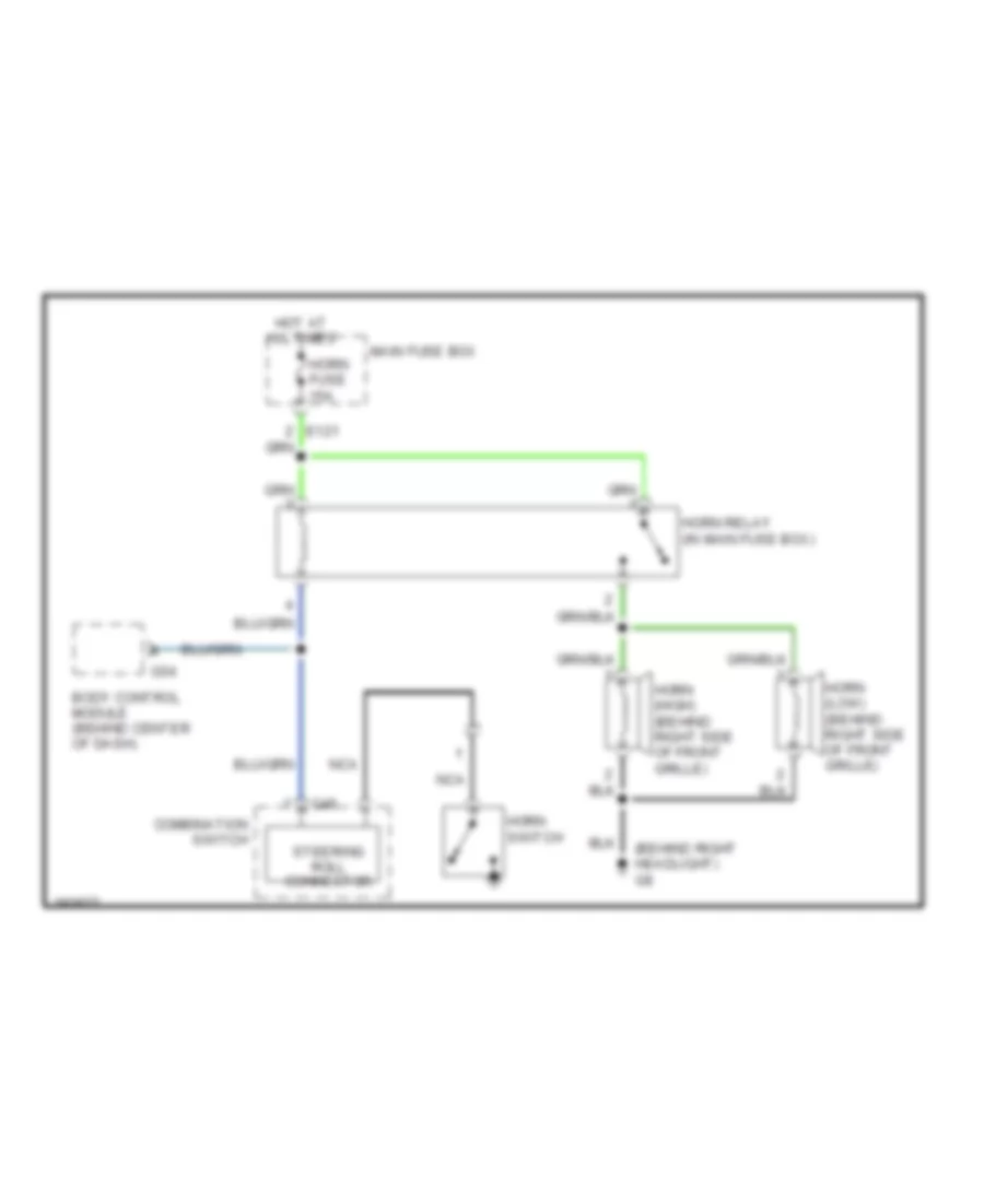
Horn Wiring Diagram for Suzuki XL-7 LX 2005
 https://portal-diagnostov.com/license.html
Automotive Electricians Portal FZCO
Automotive Electricians Portal FZCO
https://portal-diagnostov.com/license.html
https://portal-diagnostov.com/license.html
Automotive Electricians Portal FZCO
Automotive Electricians Portal FZCOList of elements for Horn Wiring Diagram for Suzuki XL-7 LX 2005:
- (behind right headlight) g8
- Body control module (behind center of dash)
- Combination switch
- E121
- G46
- G54
- Horn (high) (behind right side of front grille)
- Horn (low) (behind right side of front grille)
- Horn fuse 15a
- Horn relay (in main fuse box)
- Horn switch
- Hot at all times
- Main fuse box
- Nca
- Steering roll connector
INSTRUMENT CLUSTER
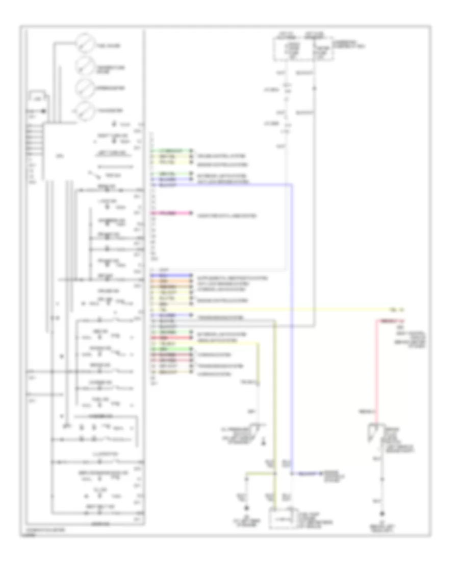
Instrument Cluster Wiring Diagram for Suzuki XL-7 LX 2005
 https://portal-diagnostov.com/license.html
Automotive Electricians Portal FZCO
Automotive Electricians Portal FZCO
https://portal-diagnostov.com/license.html
https://portal-diagnostov.com/license.html
Automotive Electricians Portal FZCO
Automotive Electricians Portal FZCOList of elements for Instrument Cluster Wiring Diagram for Suzuki XL-7 LX 2005:
- Abs ind
- Air bag ind
- Air press ind
- Anti-lock brakes system
- Beam ind
- Body control module (behind center of dash)
- Brake fluid level switch (left rear of engine compt)
- Brake ind
- Charge ind
- Combination meter
- Computer data lines system
- Cpu
- Cruise control system
- Cruise ind
- Door ind
- Drl ind
- Engine controls system
- Exterior lights system
- Fr-4wd ind
- Fuel gauge
- Fuel ind
- Fuel pump & gauge (at center rear of vehicle)
- G10
- G11
- G5 (at left rear of engine)
- G55
- G7 (behind left headlight)
- Headlights system
- Hot at all times
- Hot in on or start
- Illumination
- Interior lights system
- J/c (e44)
- J/c (g29)
- L 4wd ind
- Lcd
- Left turn ind
- Meter fuse 10a
- Oil ind
- Oil pressure switch (on left side of engine)
- Radio dome fuse 15a
- Red
- Right turn ind
- Rr-4wd ind
- Seat belt ind
- Service engine soon ind
- Set ind
- Speedometer
- Tachometer
- Temperature gauge
- Transmissions system
- Trip sw
- Underdash fuse/relay box
- Warning system
- Washer ind
INTERIOR LIGHTS
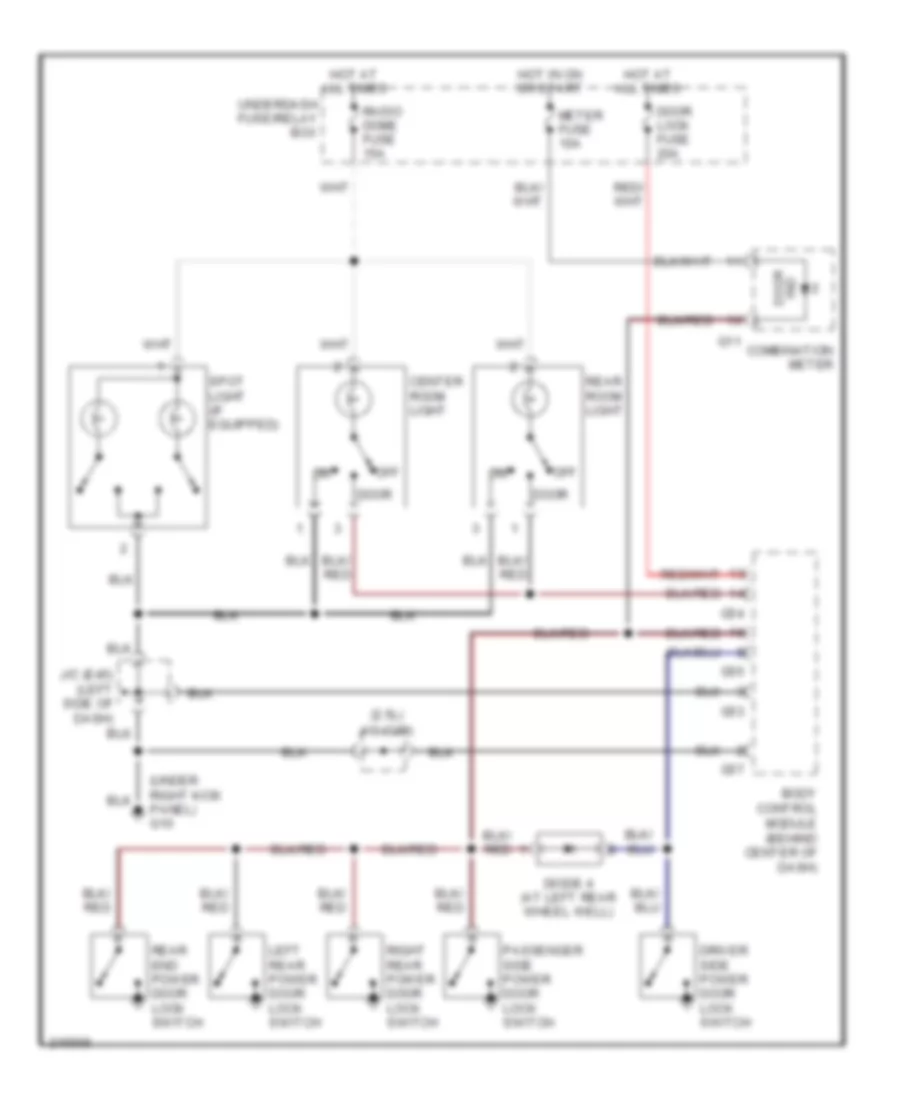
Courtesy Lamps Wiring Diagram for Suzuki XL-7 LX 2005
 https://portal-diagnostov.com/license.html
Automotive Electricians Portal FZCO
Automotive Electricians Portal FZCO
https://portal-diagnostov.com/license.html
https://portal-diagnostov.com/license.html
Automotive Electricians Portal FZCO
Automotive Electricians Portal FZCOList of elements for Courtesy Lamps Wiring Diagram for Suzuki XL-7 LX 2005:
- (2.5l)
- (under right kick panel) g10
- Body control module (behind center of dash)
- Center room light
- Combination meter
- Diode 4 (at left rear wheel well)
- Door
- Door ind
- Door lock fuse 20a
- Driver side power door lock switch
- G11
- G53
- G54
- G55
- G57
- Hot at all times
- Hot in on or start
- J/c (e45) (left side of dash)
- J/c (g29)
- Left rear power door lock switch
- Meter fuse 10a
- Off
- Passenger side power door lock switch
- Radio dome fuse 15a
- Rear end power door lock switch
- Rear room light
- Right rear power door lock switch
- Spot light (if equipped)
- Underdash fuse/relay box
Instrument Illumination Wiring Diagram for Suzuki XL-7 LX 2005
 https://portal-diagnostov.com/license.html
Automotive Electricians Portal FZCO
Automotive Electricians Portal FZCO
https://portal-diagnostov.com/license.html
https://portal-diagnostov.com/license.html
Automotive Electricians Portal FZCO
Automotive Electricians Portal FZCOList of elements for Instrument Illumination Wiring Diagram for Suzuki XL-7 LX 2005:
- Auto a/c controller (center of dash)
- Body control module (behind center of dash)
- Cigar illumi- nation
- Combination meter
- Cpu
- Driver side seat heater switch
- Front fog switch
- G11
- G3 (at left rear of engine)
- G54
- G55
- G9 (under left kick panel)
- Headlight relay 2 (in underdash fuse/relay box)
- Hot at all times
- Hot in on or start
- Illum (if equipped)
- Illumination controller (behind left side of dash)
- Illumination j/c (g16)
- Illumination j/c (g44)
- J/c (c66) (right side of dash)
- J/c (g15)
- J/c (g29)
- J/c (g35)
- Meter fuse 10a
- Mirror heater (if equipped)
- Mode select switch (a/t)
- Passenger side seat heater switch
- Radio
- Radio dome fuse 15a
- Rear a/c fan motor switch
- Tail fuse 10a
- Underdash fuse/relay box
POWER DISTRIBUTION
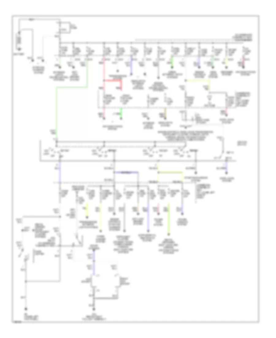
Power Distribution Wiring Diagram for Suzuki XL-7 LX 2005
 https://portal-diagnostov.com/license.html
Automotive Electricians Portal FZCO
Automotive Electricians Portal FZCO
https://portal-diagnostov.com/license.html
https://portal-diagnostov.com/license.html
Automotive Electricians Portal FZCO
Automotive Electricians Portal FZCOList of elements for Power Distribution Wiring Diagram for Suzuki XL-7 LX 2005:
- (in underhood fuse/relay box) main fuse box
- 100a
- 4wd fuse 30a
- A/c fuse 25a
- Abs fuse 10a
- Abs fuse 60a
- Acc
- Acc fuse 15a
- Acc relay (in underdash fuse/relay box)
- Acc socket
- Air bag fuse 15a
- Air conditioning system
- Alt fuse
- Anti- lock brakes system
- Anti-lock brakes system
- Battery
- Cigar fuse 25a
- Cigar lighter
- Circuit fuse 60a
- Defogger system
- Door lock fuse 20a
- Door locks system
- E120
- E121
- Engine controls system
- Engine controls,
- Engine controls, cruise control systems
- Engine controls, door locks,transmissions, instrument cluster, interior lights, warning, sound, air conditioning, computer data lines systems
- Exterior lights system
- Exterior lights, cruise control systems
- Fi fuse 15a
- Fr fog fuse 15a
- From door lock fuse
- Front acc socket
- Front blower fuse 40a
- Fuse 20a
- G12 (behind right taillight assembly)
- G9 (under left kick panel)
- H/l l fuse 15a
- H/l r fuse 15a
- Hazard fuse 10a
- Head lights system
- Headlights system
- Headlights, exterior lights systems
- Heater fuse 15a
- Ho2s fuse 15a
- Horn fuse 15a
- Horns, exterior lights
- Htr fuse 60a
- Ig coil fuse 20a
- Ig fuse 60a
- Ignition switch
- Instrument cluster, air conditioning, wiper/washer, warning, body computer systems
- J/c (e44) (right side of dash)
- Key in
- Ky1
- Ky2
- L10
- L11
- Lock
- Meter fuse 10a
- Off
- P/w
- Power tops system
- Power windows system
- Radio/ dome fuse 15a
- Rear blower fuse 20a
- Red
- Rr def fuse 25a
- Seats, defogger, body computer, mirrors, air conditioning systems
- Seats, mirrors, sound, instrument cluster systems
- Sound systems
- Start
- Starting/ charging
- Starting/ charging systems
- Starting/charging system
- Stop fuse 15a
- Sun roof fuse 25a
- System
- Systems
- Tail fuse 10a
- To acc fuse
- Transmissions system
- Transmissions, exterior lights systems
- Turn back fuse 10a
- Underdash fuse/relay box (at lower left side of dash)
- Wiper washer fuse 20a
- Wiper/ washer system
POWER DOOR LOCKS
Power Door Locks Wiring Diagram for Suzuki XL-7 LX 2005
 https://portal-diagnostov.com/license.html
Automotive Electricians Portal FZCO
Automotive Electricians Portal FZCO
https://portal-diagnostov.com/license.html
https://portal-diagnostov.com/license.html
Automotive Electricians Portal FZCO
Automotive Electricians Portal FZCOList of elements for Power Door Locks Wiring Diagram for Suzuki XL-7 LX 2005:
- (right side of dash) j/c (e43)
- Body control module (behind center of dash)
- Combination meter
- Diode 4 (at left rear wheel well)
- Door ind
- Door lock fuse 20a
- Driver side front power door lock switch
- Driver side power door lock motor (in left front door)
- Driver side power door lock switch
- Driver side rear power door lock switch
- G10 (under right kick panel)
- G11
- G12 (behind right taillight assembly)
- G53
- G54
- G55
- G56
- G57
- G9 (under left kick panel)
- Hot at all times
- Hot in on or start
- Ignition switch (key-in)
- J/c (e42) (right side of dash)
- J/c (e43) (right side of dash)
- J/c (e44) (right side of dash)
- J/c (e45) (left side of dash)
- J/c (l04)
- Keyless controller (at lower left side of dash)
- Left rear power door lock motor (in left rear door)
- Left rear power door lock switch
- Lock
- Meter fuse 10a
- Off
- Passenger side front power door lock switch
- Passenger side power door lock motor (in right front door)
- Passenger side power door lock switch
- Passenger side rear power door lock switch
- Pnk
- Radio dome fuse 15a
- Rear end power door lock motor (at lower left side of rear door)
- Rear end power door lock switch
- Right rear power door lock motor (in right rear door)
- Right rear power door lock switch
- Turn signal light relay & answer back relay (in underdash fuse/relay box)
- Un- lock
- Underdash fuse/relay box
- Unlock
POWER MIRRORS
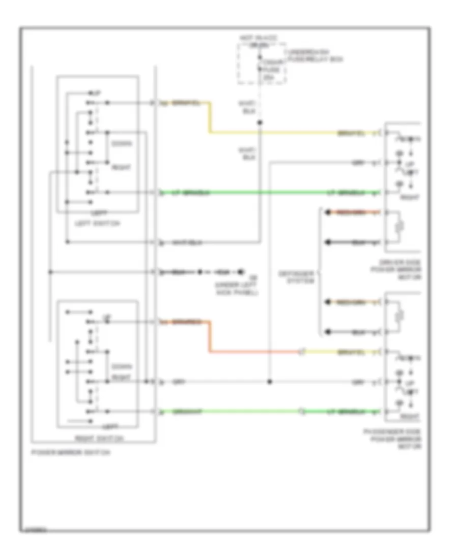
Power Mirrors Wiring Diagram for Suzuki XL-7 LX 2005
 https://portal-diagnostov.com/license.html
Automotive Electricians Portal FZCO
Automotive Electricians Portal FZCO
https://portal-diagnostov.com/license.html
https://portal-diagnostov.com/license.html
Automotive Electricians Portal FZCO
Automotive Electricians Portal FZCOList of elements for Power Mirrors Wiring Diagram for Suzuki XL-7 LX 2005:
- Cigar fuse 25a
- Defogger system
- Down
- Driver side power mirror motor
- G9 (under left kick panel)
- Hot in acc or on
- Left
- Left switch
- Passenger side power mirror motor
- Power mirror switch
- Right
- Right switch
- Underdash fuse/relay box
- Up left
POWER SEATS
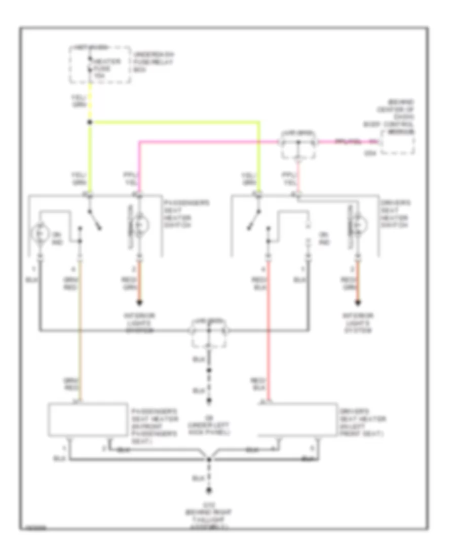
Heated Seats Wiring Diagram for Suzuki XL-7 LX 2005
 https://portal-diagnostov.com/license.html
Automotive Electricians Portal FZCO
Automotive Electricians Portal FZCO
https://portal-diagnostov.com/license.html
https://portal-diagnostov.com/license.html
Automotive Electricians Portal FZCO
Automotive Electricians Portal FZCOList of elements for Heated Seats Wiring Diagram for Suzuki XL-7 LX 2005:
- (behind center of dash) body control module
- Driver's seat heater (in left front seat)
- Driver's seat heater switch
- G12 (behind right taillight assembly)
- G54
- G9 (under left kick panel)
- Heater fuse 15a
- Hot in on
- Illumination
- Interior lights system
- J/c (g16)
- J/c (g35)
- On ind
- Passenger's seat heater (in front passenger's seat)
- Passenger's seat heater switch
- Underdash fuse/relay box
POWER TOP/SUNROOF
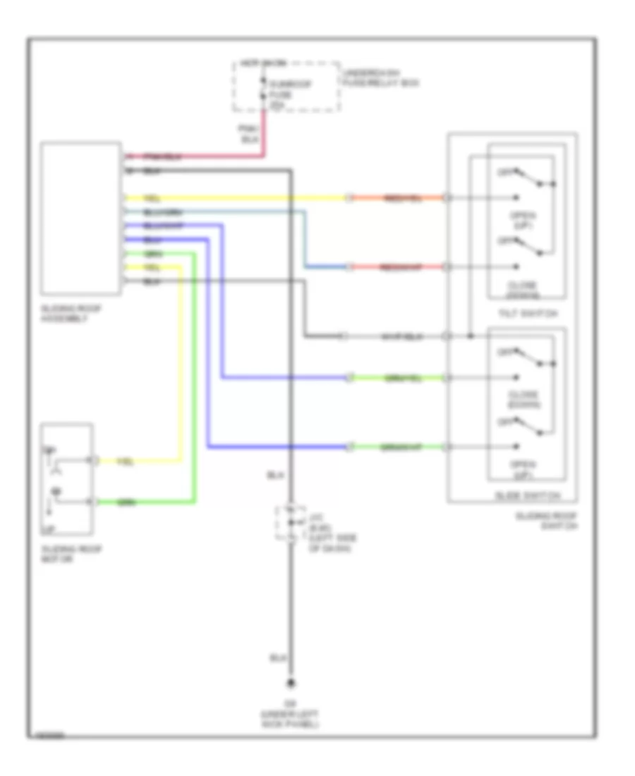
Power Top/Sunroof Wiring Diagram for Suzuki XL-7 LX 2005
 https://portal-diagnostov.com/license.html
Automotive Electricians Portal FZCO
Automotive Electricians Portal FZCO
https://portal-diagnostov.com/license.html
https://portal-diagnostov.com/license.html
Automotive Electricians Portal FZCO
Automotive Electricians Portal FZCOList of elements for Power Top/Sunroof Wiring Diagram for Suzuki XL-7 LX 2005:
- Close (down)
- G9 (under left kick panel)
- Hot in on
- J/c (e45) (left side of dash)
- Off
- Open (up)
- Slide switch
- Sliding roof assembly
- Sliding roof motor
- Sliding roof switch
- Sunroof fuse 25a
- Tilt switch
- Underdash fuse/relay box
POWER WINDOWS
Power Windows Wiring Diagram for Suzuki XL-7 LX 2005
 https://portal-diagnostov.com/license.html
Automotive Electricians Portal FZCO
Automotive Electricians Portal FZCO
https://portal-diagnostov.com/license.html
https://portal-diagnostov.com/license.html
Automotive Electricians Portal FZCO
Automotive Electricians Portal FZCOList of elements for Power Windows Wiring Diagram for Suzuki XL-7 LX 2005:
- Auto circuit
- G9 (under left kick panel)
- Hot in run
- Left front power window motor (in left front door)
- Left rear power window motor (in left rear door)
- Left rear power window sub-switch
- Lock
- Off
- Power window fuse 20a
- Power window main switch
- Red
- Right front power window motor (in right front door)
- Right front power window sub switch
- Right rear power window motor (in right rear door)
- Right rear power window sub-switch
- Underdash fuse/relay box
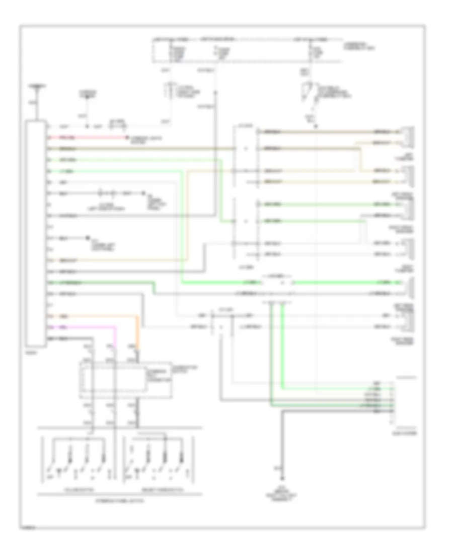
RADIO
Radio Wiring Diagram for Suzuki XL-7 LX 2005
 https://portal-diagnostov.com/license.html
Automotive Electricians Portal FZCO
Automotive Electricians Portal FZCO
https://portal-diagnostov.com/license.html
https://portal-diagnostov.com/license.html
Automotive Electricians Portal FZCO
Automotive Electricians Portal FZCOList of elements for Radio Wiring Diagram for Suzuki XL-7 LX 2005:
- Acc fuse 15a
- Acc relay (in underdash fuse/relay box)
- Antenna
- Cigar fuse 25a
- Combination switch
- G12 (behind right taillight assembly)
- G17 (under left kick panel)
- G9 (under left kick panel)
- Hot at all times
- Hot in acc or on
- Interior lights system
- J/c (e44) (right side of dash)
- J/c (g15)
- J/c (g29)
- J/c (g35) (left side of dash)
- J/c (g90)
- J/c (l53)
- J/c (l54)
- Left front speaker
- Left rear speaker
- Left tweeter
- Mode
- Mute
- Nca
- Off
- Radio
- Radio/ dome fuse 15a
- Right front speaker
- Right rear speaker
- Right tweeter
- Seek+
- Seek-
- Select mode switch
- Steering roll connector
- Steering wheel switch
- Sub woofer
- Underdash fuse/relay box
- Vol+
- Vol-
- Volume switch
- Warning system
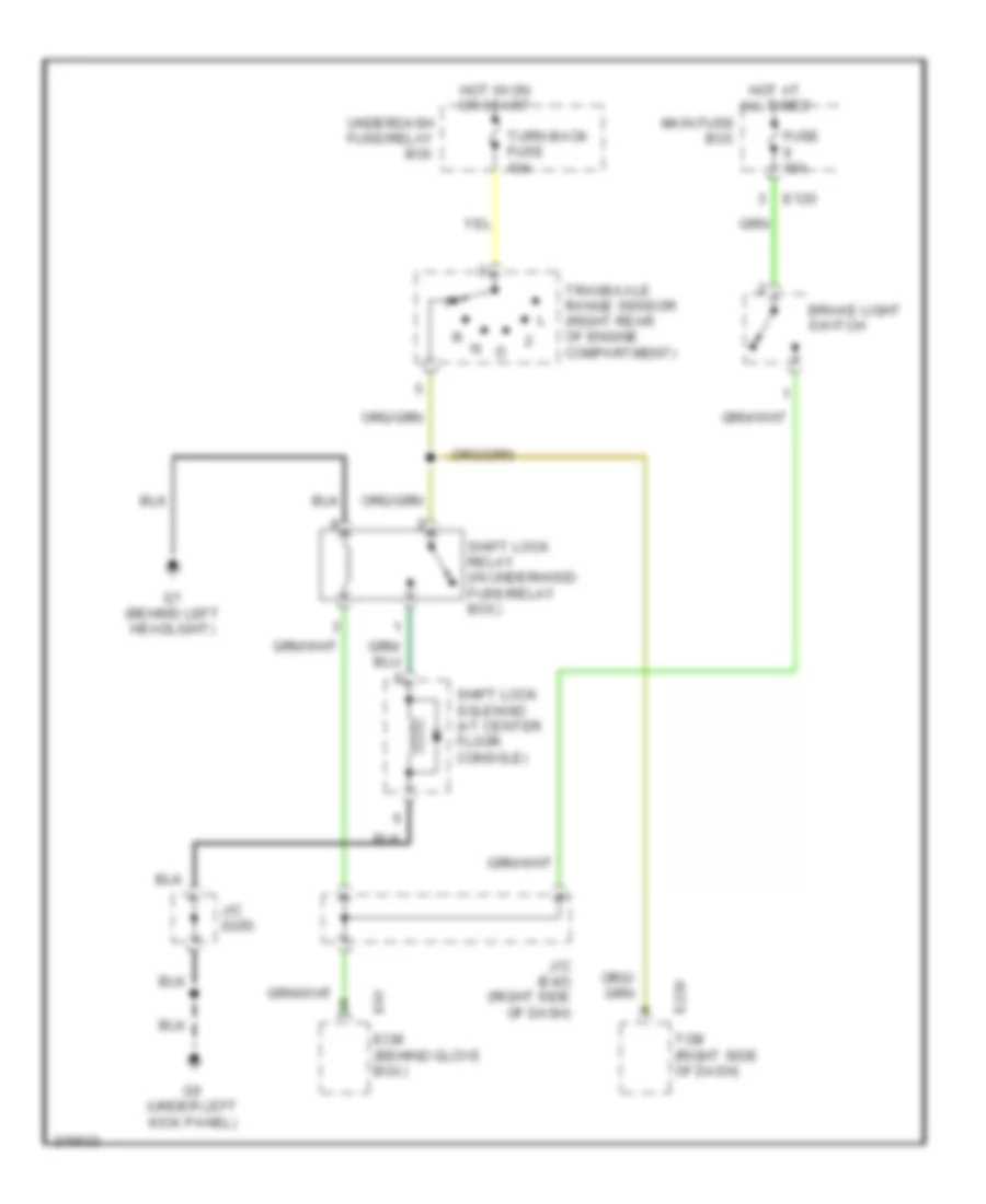
SHIFT INTERLOCK
Shift Interlock Wiring Diagram for Suzuki XL-7 LX 2005
 https://portal-diagnostov.com/license.html
Automotive Electricians Portal FZCO
Automotive Electricians Portal FZCO
https://portal-diagnostov.com/license.html
https://portal-diagnostov.com/license.html
Automotive Electricians Portal FZCO
Automotive Electricians Portal FZCOList of elements for Shift Interlock Wiring Diagram for Suzuki XL-7 LX 2005:
- Brake light switch
- E120
- E228 tcm (right side of dash)
- E61 ecm (behind glove box)
- Fuse 15a
- G7 (behind left headlight)
- G9 (under left kick panel)
- Hot at all times
- Hot in on or start
- J/c (e42) (right side of dash)
- J/c (g29)
- Main fuse box
- Shift lock relay (in underhood fuse/relay box)
- Shift lock solenoid (at center floor console)
- Transaxle range sensor (right rear of engine compartment)
- Turn back fuse 10a
- Underdash fuse/relay box
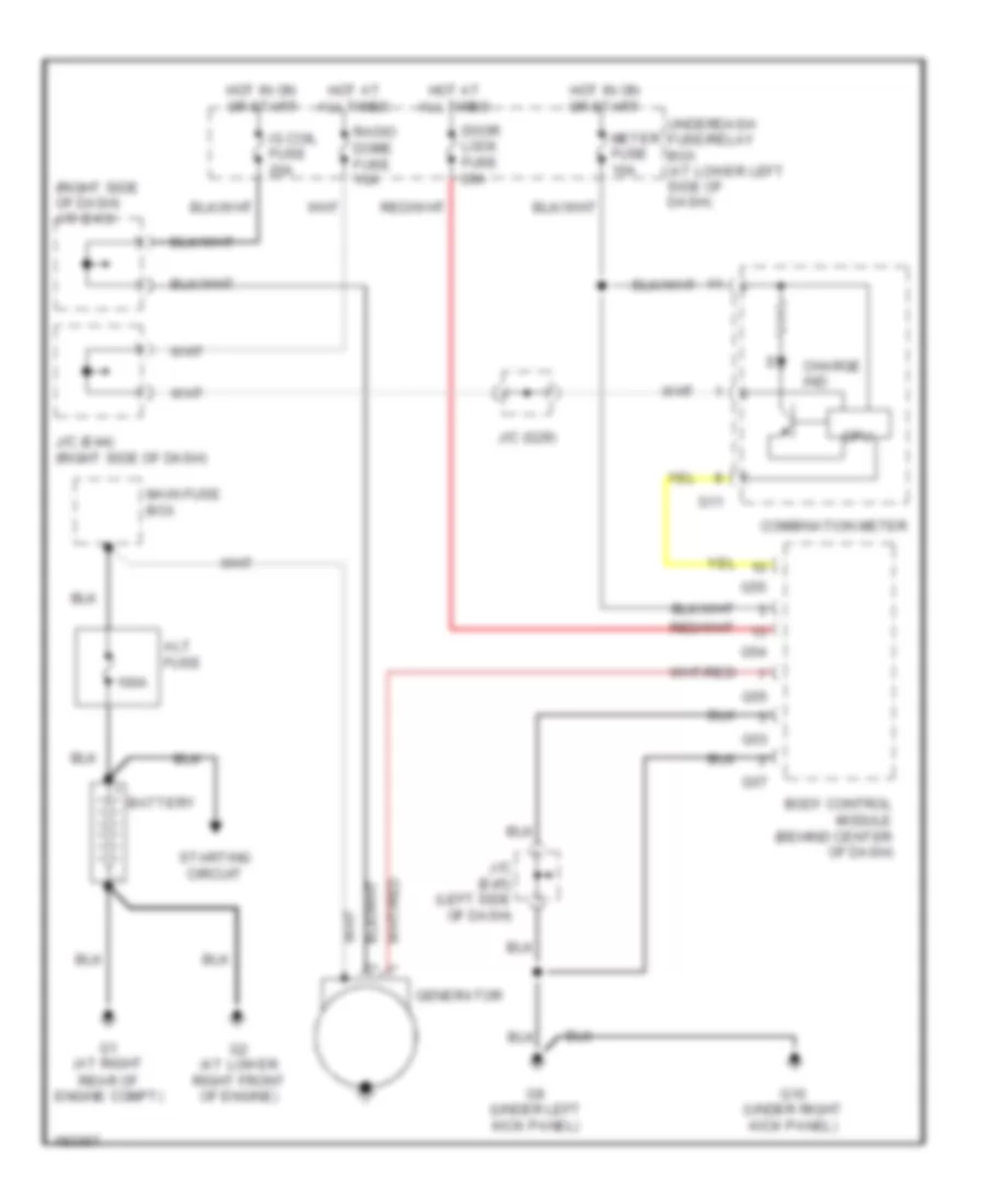
STARTING/CHARGING
Charging Wiring Diagram for Suzuki XL-7 LX 2005
 https://portal-diagnostov.com/license.html
Automotive Electricians Portal FZCO
Automotive Electricians Portal FZCO
https://portal-diagnostov.com/license.html
https://portal-diagnostov.com/license.html
Automotive Electricians Portal FZCO
Automotive Electricians Portal FZCOList of elements for Charging Wiring Diagram for Suzuki XL-7 LX 2005:
- (right side of dash) j/c (e43)
- 100a
- Alt fuse
- Battery
- Body control module (behind center of dash)
- Charge ind
- Combination meter
- Cpu
- Door lock fuse 20a
- G1 (at right rear of engine compt)
- G10 (under right kick panel)
- G11
- G2 (at lower right front of engine)
- G53
- G54
- G55
- G57
- G9 (under left kick panel)
- Generator
- Hot at all times
- Hot in on or start
- Hot in on or start
- Ig coil fuse 20a
- J/c (e44) (right side of dash)
- J/c (e45) (left side of dash)
- J/c (g29)
- Main fuse box
- Meter fuse 10a
- Radio dome fuse 15a
- Starting circuit
- Underdash fuse/relay box (at lower left side of dash)
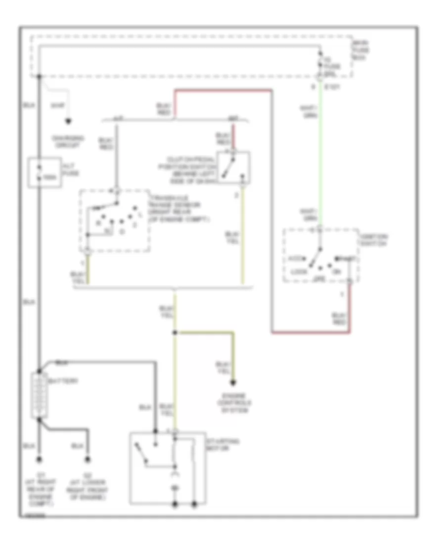
Starting Wiring Diagram for Suzuki XL-7 LX 2005
 https://portal-diagnostov.com/license.html
Automotive Electricians Portal FZCO
Automotive Electricians Portal FZCO
https://portal-diagnostov.com/license.html
https://portal-diagnostov.com/license.html
Automotive Electricians Portal FZCO
Automotive Electricians Portal FZCOList of elements for Starting Wiring Diagram for Suzuki XL-7 LX 2005:
- 100a
- A/t
- Acc
- Alt fuse
- Battery
- Charging circuit
- Clutch pedal position switch (behind left side of dash)
- E121
- Engine controls system
- G1 (at right rear of engine compt)
- G2 (at lower right front of engine)
- Ig fuse 60a
- Ignition switch
- Lock
- M/t
- Main fuse box
- Off
- Start
- Starting motor
- Transaxle range sensor (right rear of engine compt)
SUPPLEMENTAL RESTRAINTS
Supplemental Restraints Wiring Diagram (1 of 2) for Suzuki XL-7 LX 2005
 https://portal-diagnostov.com/license.html
Automotive Electricians Portal FZCO
Automotive Electricians Portal FZCO
https://portal-diagnostov.com/license.html
https://portal-diagnostov.com/license.html
Automotive Electricians Portal FZCO
Automotive Electricians Portal FZCOList of elements for Supplemental Restraints Wiring Diagram (1 of 2) for Suzuki XL-7 LX 2005:
- (under center console)
- Ab control module (behind lower center of dash)
- Air bag fuse 41 15a
- Body control module (behind center of dash)
- Computer data lines system
- Connection detection pin
- Contact coil
- Diagnosis connector (behind lower left side of dash)
- Driver inflator
- G11
- G58
- G92
- G93
- Hot at all times
- Hot in on or start
- Individual circuit fuse box
- J/c
- Left forward sensor (left front of engine)
- Left pretensioner
- Passenger inflator
- Pnk
- Radio dome fuse 35 15a
- Red
- Right forward sensor (right front of eng compt)
- Right pretensioner
Supplemental Restraints Wiring Diagram (2 of 2) for Suzuki XL-7 LX 2005
 https://portal-diagnostov.com/license.html
Automotive Electricians Portal FZCO
Automotive Electricians Portal FZCO
https://portal-diagnostov.com/license.html
https://portal-diagnostov.com/license.html
Automotive Electricians Portal FZCO
Automotive Electricians Portal FZCOList of elements for Supplemental Restraints Wiring Diagram (2 of 2) for Suzuki XL-7 LX 2005:
- (under right kick panel)
- Air bag ind
- Combination meter
- Computer data lines system
- Cpu
- G10
- G11
- Hot in on or start
- Individual circuit fuse box
- L66
- L68
- Left front seat sensor
- Left position sensor
- Left rear seat sensor
- Left seat belt switch
- Meter fuse 43 10a
- Ocm
- Red
- Right front seat sensor
- Right position sensor
- Right rear seat sensor
- Right seat belt switch
- Seat belt ind
TRANSMISSION
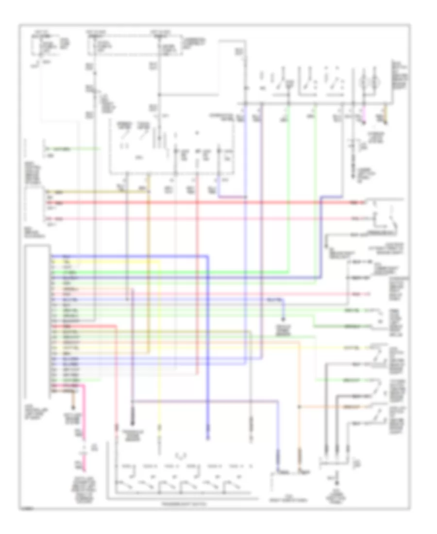
4WD Wiring Diagram for Suzuki XL-7 LX 2005
 https://portal-diagnostov.com/license.html
Automotive Electricians Portal FZCO
Automotive Electricians Portal FZCO
https://portal-diagnostov.com/license.html
https://portal-diagnostov.com/license.html
Automotive Electricians Portal FZCO
Automotive Electricians Portal FZCOList of elements for 4WD Wiring Diagram for Suzuki XL-7 LX 2005:
- (under left kick panel) g9
- 2wd/ 4wd
- 4wd controller (left side of dash)
- 4wd fr ind
- 4wd l ind
- 4wd low switch (at center rear of engine compt)
- 4wd pump (at right front of engine compt)
- 4wd rr ind
- 4wd switch (at center rear of engine compt)
- Anti-lock brakes system
- Body control module (behind center of dash)
- C51-1
- Combination meter
- Cpu
- Data link connector (below left side of dash, right of steering column)
- Diagnosis switch (behind right end of dash)
- E121
- E228
- E229
- E61
- Ecm (behind glove box)
- Free axle motor (left side of front grille)
- G10
- G10 (under right kick panel)
- G11
- G15 (under right kick panel)
- G56
- G8 (behind right headlight)
- Hot at all times
- Hot in acc or run
- Ig coil fuse 40 20a
- Interior lights system
- J/c c67
- J/c e43 (right side of dash)
- J/c g16
- J/c g35
- Main fuse box
- Meter fuse 43 10a
- Pnk
- Pressure sw
- Red
- Speedo- meter
- Stop fuse16 30a
- T/f fork switch (center rear of engine compt)
- Tacho- meter
- Tcm (right side of dash)
- Transaxle range sensor
- Transfer shift switch
- Underdash fuse/relay box
- Vehicle speed sensor
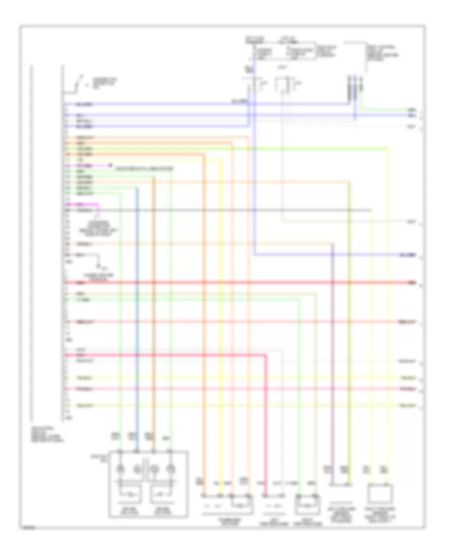
A/T Wiring Diagram (1 of 2) for Suzuki XL-7 LX 2005
 https://portal-diagnostov.com/license.html
Automotive Electricians Portal FZCO
Automotive Electricians Portal FZCO
https://portal-diagnostov.com/license.html
https://portal-diagnostov.com/license.html
Automotive Electricians Portal FZCO
Automotive Electricians Portal FZCOList of elements for A/T Wiring Diagram (1 of 2) for Suzuki XL-7 LX 2005:
- 4wd circuit
- A/t diagnosis connector
- Actuator w/ control module (left front of eng compt)
- Brake light switch
- C51-1
- Computer data lines system
- Data link connector (below left side of dash, right of steering column)
- E120
- E228
- E229
- E61
- Ecm (behind glove box)
- G3 (at left rear of engine)
- Hot at all times
- Hot in acc or run
- Ig coil fuse 40 20a
- J/c e42 (right side of dash)
- J/c e43 (right side of dash)
- J/c e44 (right side of dash)
- J/c g16
- Linear solenoid
- Look-up linear solenoid
- Main fuse box
- Radio dome fuse 9 15a
- Red
- Shift solenoid
- Shift solenoid (center rear of engine compt)
- Solenoid relay
- Stop fuse 9 15a
- Tcm (right side of dash)
- Throttle linear solenoid
- Underdash fuse/relay box
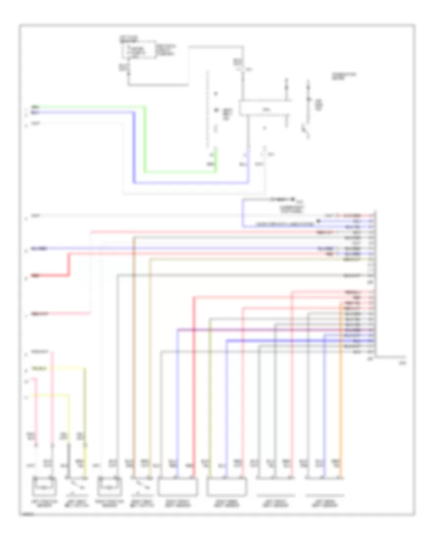
A/T Wiring Diagram (2 of 2) for Suzuki XL-7 LX 2005
 https://portal-diagnostov.com/license.html
Automotive Electricians Portal FZCO
Automotive Electricians Portal FZCO
https://portal-diagnostov.com/license.html
https://portal-diagnostov.com/license.html
Automotive Electricians Portal FZCO
Automotive Electricians Portal FZCOList of elements for A/T Wiring Diagram (2 of 2) for Suzuki XL-7 LX 2005:
- (under left kick panel) g9
- 4wd circuit
- Body control module (behind center of dash)
- Combination meter
- Cpu
- Exterior lights system
- G10
- G11
- G55
- G9 (under left kick panel)
- Hot in acc or run
- Input sensor (at center rear of engine)
- Interior lights system
- J/c e230
- J/c g35
- Meter fuse 43 10a
- Mode select switch
- Nca
- Normal
- O/d cut switch
- O/d off ind
- Output shaft speed sensor (at center rear of engine compt)
- Power
- Pwr ind
- Red
- Shift interlock system
- Starting/ charging system
- Transaxle range sensor (right rear of engine compt)
- Turn/ back fuse 19 10a
- Underdash fuse/relay box
WARNING SYSTEMS
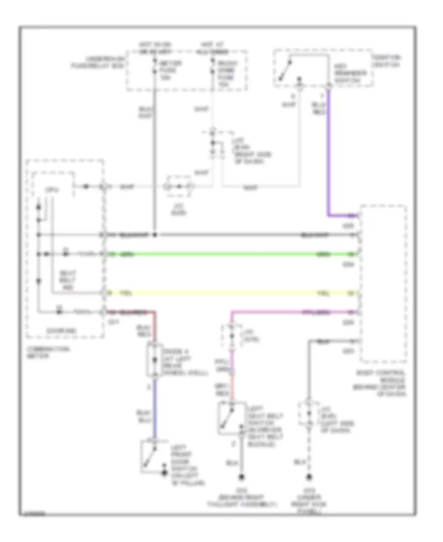
Key Reminder & Seat Belt Warning Wiring Diagram for Suzuki XL-7 LX 2005
 https://portal-diagnostov.com/license.html
Automotive Electricians Portal FZCO
Automotive Electricians Portal FZCO
https://portal-diagnostov.com/license.html
https://portal-diagnostov.com/license.html
Automotive Electricians Portal FZCO
Automotive Electricians Portal FZCOList of elements for Key Reminder & Seat Belt Warning Wiring Diagram for Suzuki XL-7 LX 2005:
- Body control module (behind center of dash)
- Combination meter
- Cpu
- Diode 4 (at left rear wheel well)
- Door ind
- G10 (under right kick panel)
- G11
- G12 (behind right taillight assembly)
- G53
- G54
- G55
- Hot at all times
- Hot in on or start
- Ignition switch
- J/c (e44) (right side of dash)
- J/c (e45) (left side of dash)
- J/c (g16)
- J/c (g29)
- Key reminder switch
- Left front door switch (on left "b" pillar)
- Left seat belt switch (in driver seat belt buckle)
- Meter fuse 10a
- Radio dome fuse 15a
- Seat belt ind
- Underdash fuse/relay box
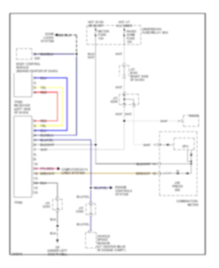
Tire Pressure Monitoring Wiring Diagram for Suzuki XL-7 LX 2005
 https://portal-diagnostov.com/license.html
Automotive Electricians Portal FZCO
Automotive Electricians Portal FZCO
https://portal-diagnostov.com/license.html
https://portal-diagnostov.com/license.html
Automotive Electricians Portal FZCO
Automotive Electricians Portal FZCOList of elements for Tire Pressure Monitoring Wiring Diagram for Suzuki XL-7 LX 2005:
- Air press ind
- Body control module (behind center of dash)
- Combination
- Computer data lines system
- Cpu
- Door locks system
- Engine controls system
- G55
- G9 (under left kick panel)
- Hot at all times
- Hot in on or start
- J/c (c69)
- J/c (e44) (right side of dash)
- J/c (g29)
- J/c (g35)
- Meter
- Meter fuse 10a
- Radio
- Radio dome fuse 15a
- Red
- Tpms
- Tpms receiver (left side of dash)
- Underdash fuse/relay box
- Vehicle speed sensor (at center rear of engine compt)
WIPER/WASHER
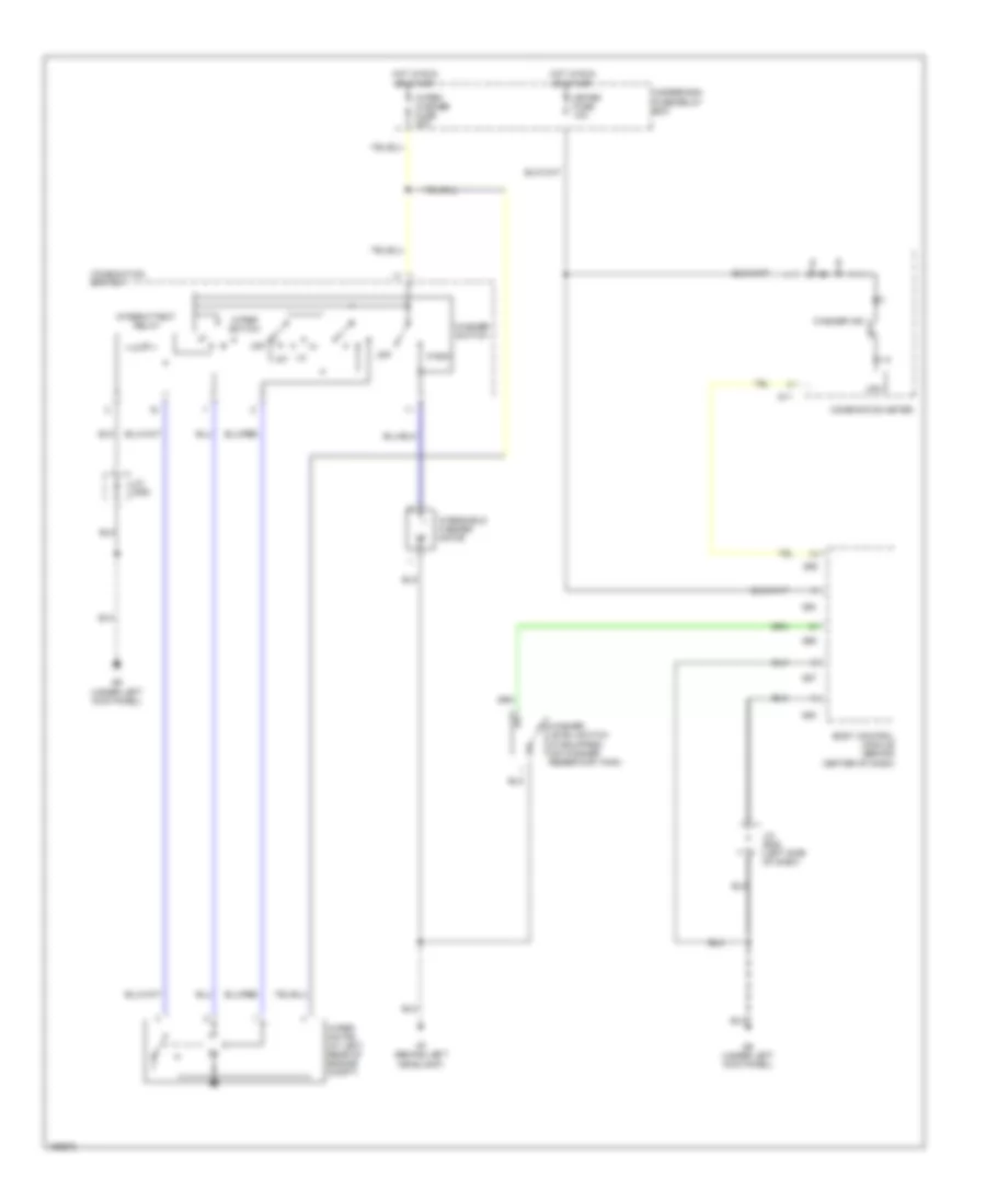
Front Wiper/Washer Wiring Diagram for Suzuki XL-7 LX 2005
 https://portal-diagnostov.com/license.html
Automotive Electricians Portal FZCO
Automotive Electricians Portal FZCO
https://portal-diagnostov.com/license.html
https://portal-diagnostov.com/license.html
Automotive Electricians Portal FZCO
Automotive Electricians Portal FZCOList of elements for Front Wiper/Washer Wiring Diagram for Suzuki XL-7 LX 2005:
- Body control module (behind center of dash)
- Combination meter
- Combination switch
- Cpu
- G11
- G53
- G54
- G55
- G56
- G57
- G7 (behind left headlight)
- G9 (under left kick panel)
- Hot in run or start
- Intermittent relay
- J/c (e45) (left side of dash)
- J/c (g35)
- Lo int
- Meter fuse 10a
- Off
- Underdash fuse/relay box
- Wash
- Washer ind
- Washer level switch (if equipped) (on washer reservoir tank)
- Washer switch
- Windshield washer motor
- Wiper motor (at left rear of engine compt)
- Wiper switch
- Wiper washer fuse 20a
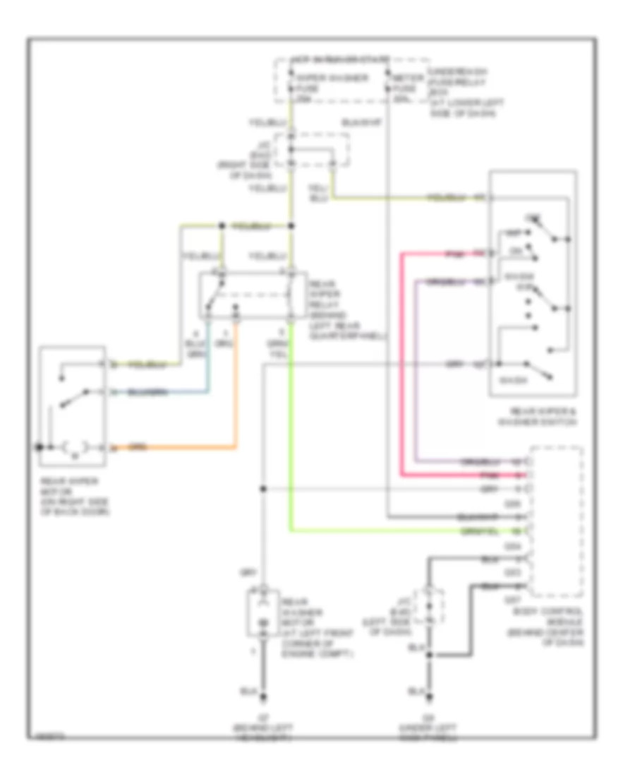
Rear Wiper/Washer Wiring Diagram for Suzuki XL-7 LX 2005
 https://portal-diagnostov.com/license.html
Automotive Electricians Portal FZCO
Automotive Electricians Portal FZCO
https://portal-diagnostov.com/license.html
https://portal-diagnostov.com/license.html
Automotive Electricians Portal FZCO
Automotive Electricians Portal FZCOList of elements for Rear Wiper/Washer Wiring Diagram for Suzuki XL-7 LX 2005:
- Body control module (behind center of dash)
- G53
- G54
- G56
- G57
- G7 (behind left headlight)
- G9 (under left kick panel)
- Hot in run or start
- Int
- J/c (e42) (right side of dash)
- J/c (e45) (left side of dash)
- Meter fuse 10a
- Off
- Pnk
- Rear washer motor (at left front corner of engine compt)
- Rear wiper & washer switch
- Rear wiper motor (on right side of back door)
- Rear wiper relay (behind left rear quarterpanel)
- Underdash fuse/relay box (at lower left side of dash)
- Wash
- Wash/ wip
- Wiper washer fuse 20a

 Čeština
 Dansk
Dansk Deutsch
 Ελληνικά
 English
 English
 Español
 Suomi
Suomi Français
 Français
 עברית
עברית Hrvatski
 Magyar
 Italiano
 日本語
日本語 한국어
한국어 Nederlands
 Polski
 Português
 Português
 Română
 Русский
 Slovenčina
 Slovenščina
 Svenska
 中文 (中国)
