ANTI-LOCK BRAKES
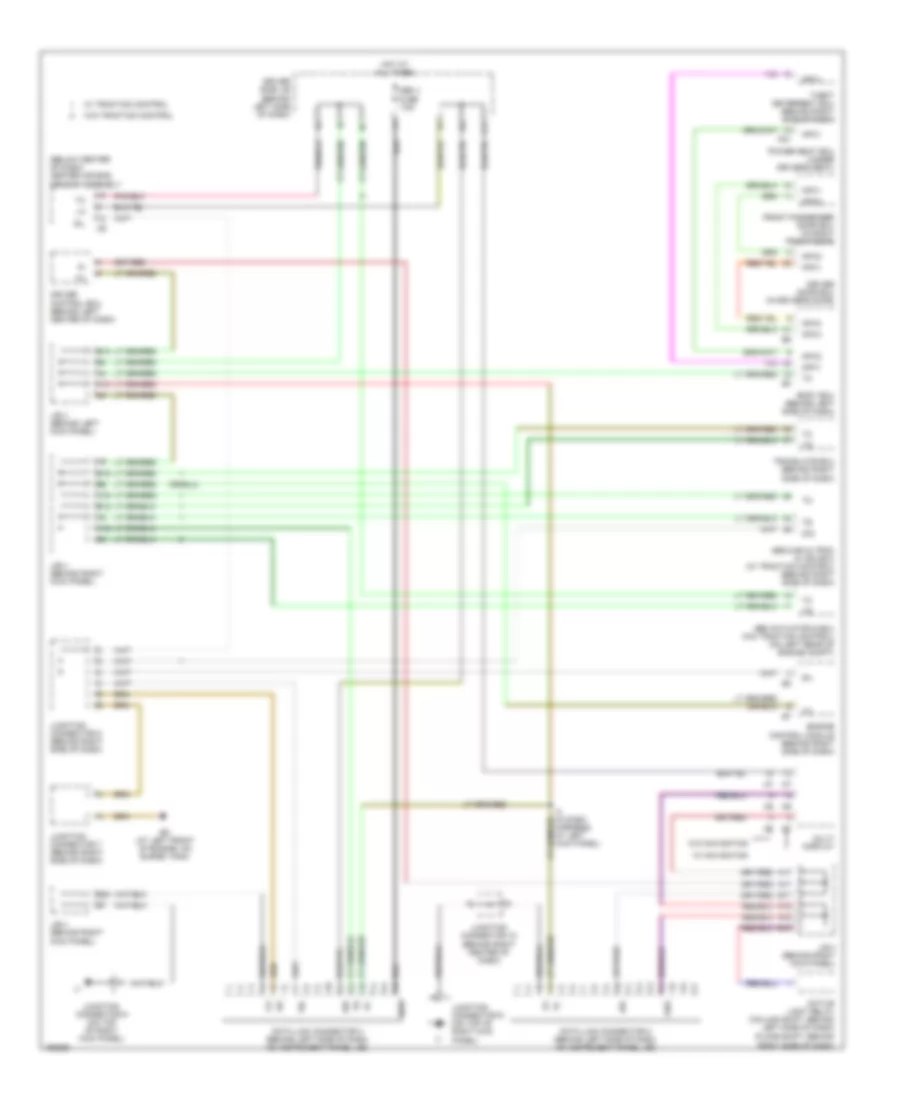
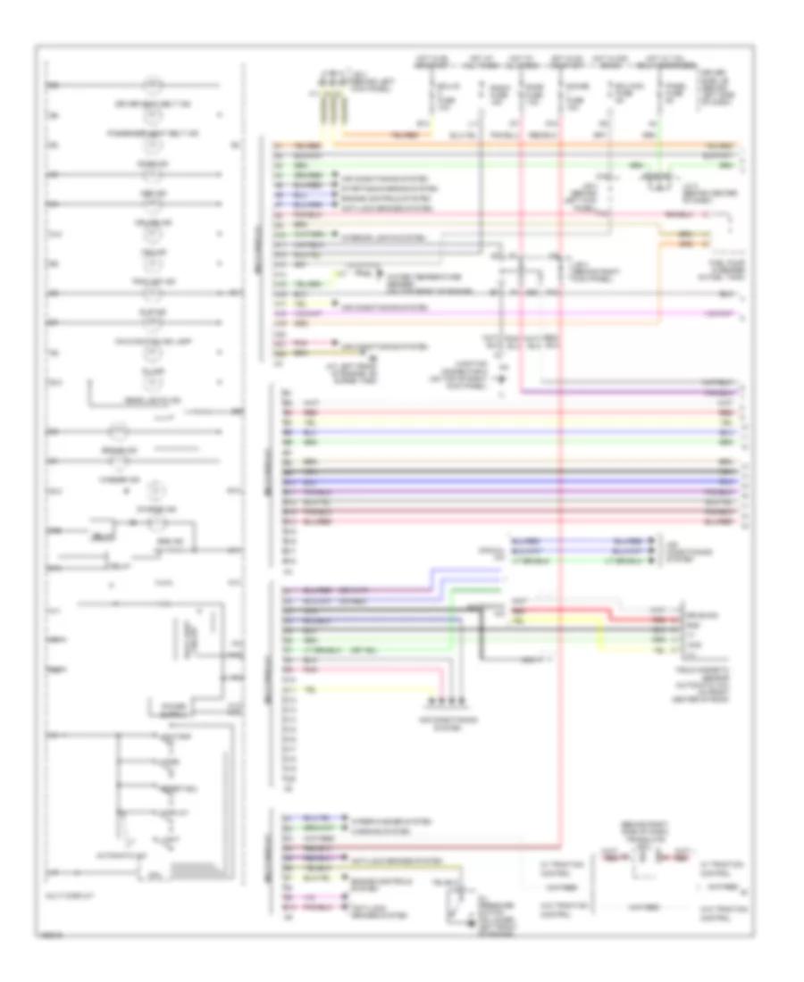
Anti-lock Brakes Wiring Diagram, with Traction Control (1 of 3) for Toyota Avalon XLS 2004
 https://portal-diagnostov.com/license.html
Automotive Electricians Portal FZCO
Automotive Electricians Portal FZCO
https://portal-diagnostov.com/license.html
https://portal-diagnostov.com/license.html
Automotive Electricians Portal FZCO
Automotive Electricians Portal FZCO
List of elements for Anti-lock Brakes Wiring Diagram, with Traction Control (1 of 3) for Toyota Avalon XLS 2004:
- (at front side of right fender) ea
- (at right side of engine compt) skid control ecu w/ actuator
- (behind left side of dash) j/c 6
- (behind left side of dash) instrument panel j/b
- (behind upper right side of dash) right j/b
- (on bracket, above brake pedal) stop light switch
- +bm
- +bs
- A/t shift lever position switch (on left side of transaxle)
- Abs 1 fuse 30a
- Abs 2 fuse 40a
- Abs ind
- Acc
- Am2 fuse 15a
- B14
- B16
- B20
- B21
- B22
- Brake fluid level warning switch (on brake fluid reservoir)
- Brake ind
- Brk
- Brl
- C13
- C14
- C19
- C20
- Center j/b (behind center of dash)
- Center j/b (behind center of dash)
- Combination meter
- D/g
- Data link connector 3 (below left side of dash)
- Daytime running light relay (behind left side of dash)
- Dome fuse 15a
- Eb (except xrs: at rear left side of cylinder head) (xrs: left rear of engine)
- Ecu-ig fuse 10a
- Ed (at left front suspension tower)
- Engine room r/b (integral to engine room j/b)
- Fl+
- Fl-
- Fr+
- Fr-
- Gauge fuse 10a
- Gnd1
- Gnd2
- Hot at all times
- Hot in on or start
- Ig1
- Ignition switch
- Ind tire pressure
- Init
- Instrument panel j/b (behind left side of dash)
- J/c 3 (behind right side of dash)
- J/c 4 (behind right side of dash)
- J/c 6 (behind left side of dash)
- Left front abs speed sensor (on inside of left front wheel assembly)
- Left rear abs speed sensor (on inside of right rear wheel assembly)
- Lock
- Off
- Parking brake switch (at base of park brake lever)
- Pkb
- Red
- Right front abs speed sensor (on inside of right front wheel assembly)
- Right j/b (behind upper right side of dash)
- Right rear abs speed sensor (on inside of right rear wheel assembly)
- Rl+
- Rl-
- Rr+
- Rr-
- Sil
- Sp1
- Speedometer
- Start
- Stop fuse 15a
- Stp
- Tire pressure warning standardization switch
- Tsi
- Wtir
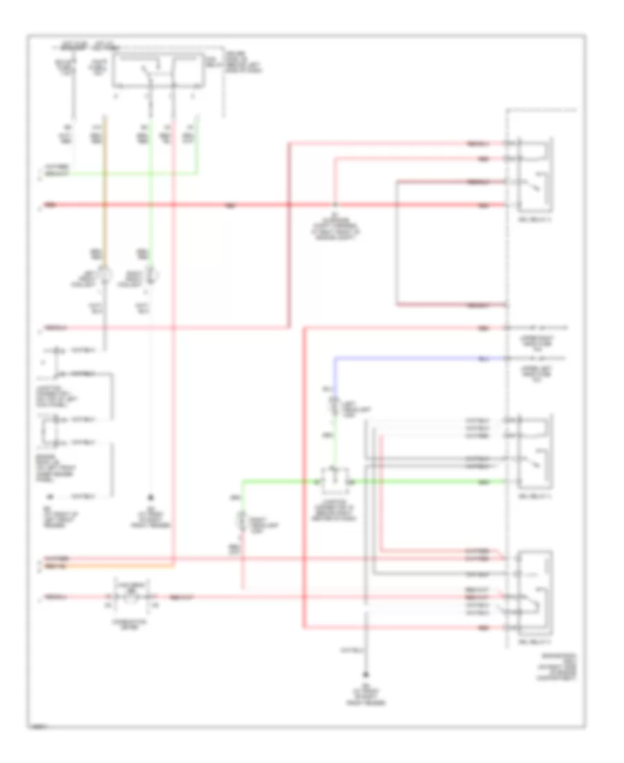
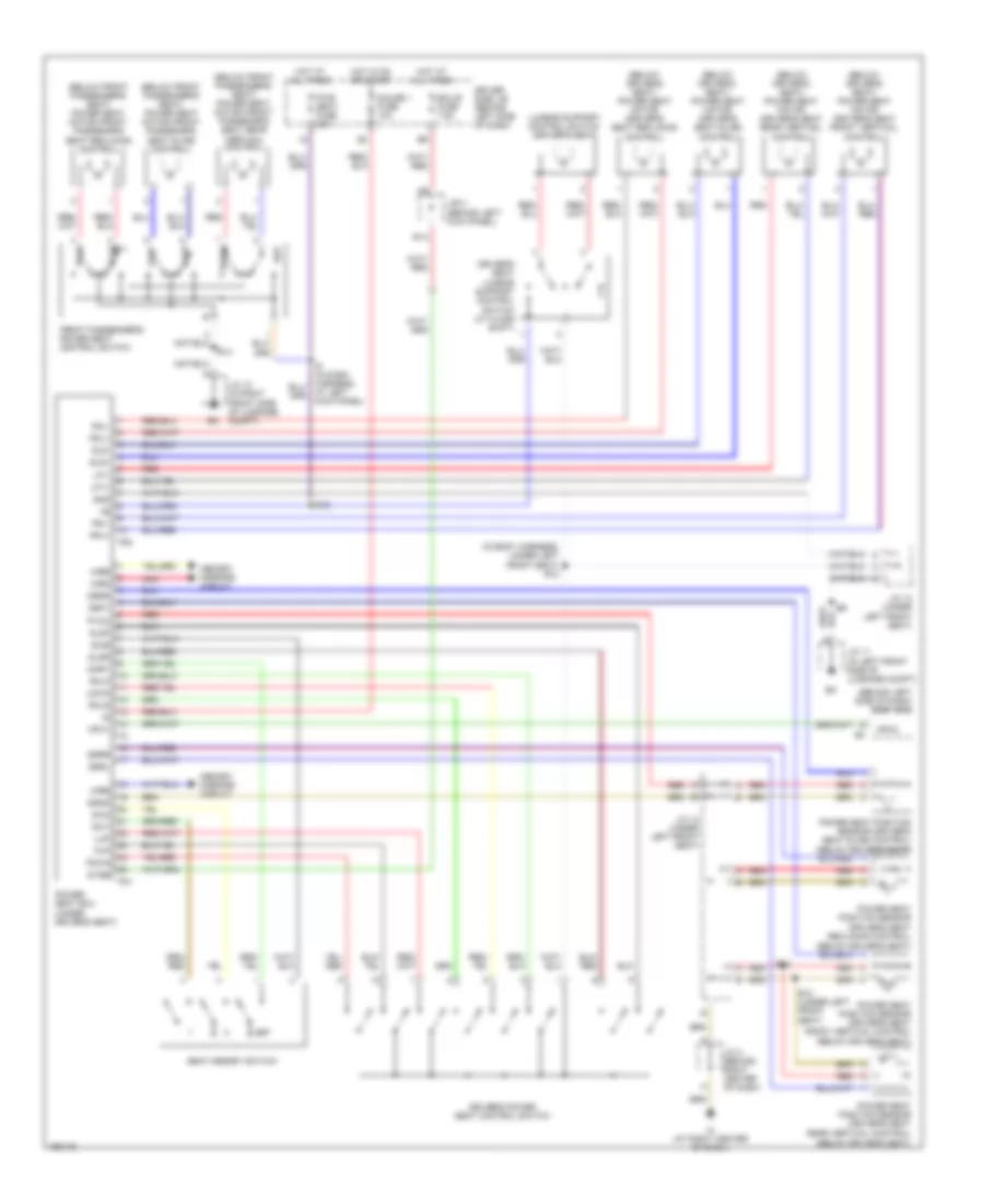
Anti-lock Brakes Wiring Diagram, with Traction Control (2 of 3) for Toyota Avalon XLS 2004
 https://portal-diagnostov.com/license.html
Automotive Electricians Portal FZCO
Automotive Electricians Portal FZCO
https://portal-diagnostov.com/license.html
https://portal-diagnostov.com/license.html
Automotive Electricians Portal FZCO
Automotive Electricians Portal FZCOList of elements for Anti-lock Brakes Wiring Diagram, with Traction Control (2 of 3) for Toyota Avalon XLS 2004:
- (behind left kick panel) j/b 3
- (behind left side of dash)
- (in dash harness, at left side of dash)
- (in dash harness, at right side of dash) i15
- (on left rear of engine compt) abs & ba & trac & vsc actuator
- A14
- A15
- A18
- Active light relay (column shift: behind left side of dash) (floor shift: behind right side of dash)
- B15
- B18
- Body ecu
- Brake fluid level warning switch (on brake fluid reservoir)
- Brl
- Ccs
- D11
- D16
- Driver side j/b (behind left side of dash)
- Ed (at front of left front fender)
- Ee (at front of left front fender)
- Eng+
- Eng-
- F16
- Gnd
- Hot at all times
- I12
- I15 (in dash harness, at right side of dash)
- Ig (at left end of dash)
- Ig1
- J/b 3 (behind left kick panel)
- J/b 4 (behind right kick panel)
- Lbl
- Lvl2
- Ml+
- Ml-
- Nca
- Neo
- Park/neutral position switch (on left side of transaxle)
- Parking brake switch (on parking brake lever bracket)
- Pkb
- Pkb2
- Red
- Rss
- Sflh
- Sflr
- Sfrh
- Sfrr
- Smc1
- Smc2
- Src1
- Src2
- Srlh
- Srlr
- Srrh
- Srrr
- Ss1
- Ss2
- Steering sensor (combination switch)
- Stop fuse 15a
- Stoplight switch (on bracket, above brake pedal)
- Translate ecu (behind right side of dash)
- Trc+
- Trc-
- Vsc+
- Vsc-
Anti-lock Brakes Wiring Diagram, with Traction Control (3 of 3) for Toyota Avalon XLS 2004
 https://portal-diagnostov.com/license.html
Automotive Electricians Portal FZCO
Automotive Electricians Portal FZCO
https://portal-diagnostov.com/license.html
https://portal-diagnostov.com/license.html
Automotive Electricians Portal FZCO
Automotive Electricians Portal FZCOList of elements for Anti-lock Brakes Wiring Diagram, with Traction Control (3 of 3) for Toyota Avalon XLS 2004:
- (behind center of dash) center j/b
- (behind left side of dash) daytime running light relay
- (in instrument panel wire, behind right side of dash) i7
- +b1
- A11
- A19
- Cty
- Dcty
- Detection
- Dmlp
- Dswd
- Dswl
- Ecu-b fuse 10a
- Ecu-ig fuse 10a
- Ehw
- Glass breakage sensor ecu (behind upper right side of dash)
- Gmic
- Gnd
- Head
- Horn
- Horns system
- Hot at all times
- Hot in on or start
- Hzad
- I1 (in instrument panel wire, at left side of dash)
- I11
- I2 (in instrument panel wire, at left side of dash)
- I8 (in instrument panel wire, behind right end of dash)
- Ind
- Instrument panel j/b (behind left side of dash, at lower finish panel)
- Integration relay
- Iout
- Irsg
- Junction connector 10 (at left side of luggage compt)
- Junction connector 6 (behind left side of dash)
- Junction connector 7 (at right kick panel)
- Ksw
- Left front door key lock & unlock switch, door unlock detection switch (at rear of left front door)
- Lock
- Lswd
- Lswp
- Luggage compartment light switch (at center rear of luggage compt)
- Mic
- Micro- phone
- Nca
- Prcty
- Red
- Rheostat
- Right front door key lock & unlock switch, door unlock detection switch (at rear of right front door)
- Right j/b (behind upper right side of dash)
- S+b
- Security ind
- Security indicator
- Srly
- Starting/ charging system
- Trig
- Turn signal flasher relay (behind left side of dash, on instrument panel j/b)
- Tvip ecu (behind right side of dash)
- Tvss
- Ul2
- Ul3
- Unlk
- Unlock warning switch (on steering column, behind ignition key cylinder)
Anti-lock Brakes Wiring Diagram, without Traction Control (1 of 2) for Toyota Avalon XLS 2004
 https://portal-diagnostov.com/license.html
Automotive Electricians Portal FZCO
Automotive Electricians Portal FZCO
https://portal-diagnostov.com/license.html
https://portal-diagnostov.com/license.html
Automotive Electricians Portal FZCO
Automotive Electricians Portal FZCOList of elements for Anti-lock Brakes Wiring Diagram, without Traction Control (1 of 2) for Toyota Avalon XLS 2004:
- (in dash harness, at left kick panel) i4
- A12
- A13
- A18
- Abs
- Abs actuator & ecu (on left rear of engine compt)
- Abs fuse 60a
- Active light relay (column shift: behind left side of dash) (floor shift: behind right side of dash)
- B13
- B14
- B18
- Bat
- Body ecu (behind left side of dash)
- Brl
- D10
- D11
- D16
- Data link connector 2 (behind left side of dash, on instrument panel j/b)
- Data link connector 3 (behind left side of dash, on instrument panel j/b)
- Diode (a/t indicator light 1) (behind center of dash, taped to harness)
- Driver side j/b (behind left side of dash)
- Ebdw
- Ecu-ig 2 fuse 10a
- Ed (at front of left front fender)
- Ee (at front of left front fender)
- Engine room j/b (on left front inner fender panel)
- Engine room r/b 5 (on left inner fender panel)
- F10
- F13
- F16
- Fl+
- Fl-
- Fr+
- Fr-
- Gauge 1 fuse 10a
- Gnd
- Gnd1
- Gnd2
- H18
- Hot at all times
- Hot in on or start
- Ig1
- J/b 3 (behind left kick panel)
- J/b 4 (behind right kick panel)
- Park/neutral position switch (on left side of transaxle)
- Parking brake switch (on parking brake lever bracket)
- Pkb
- Pkb2
- Red
- Rl+
- Rl-
- Rr+
- Rr-
- Sp1
- Stop fuse 15a
- Stoplight switch (on bracket, above brake pedal)
- Stp
Anti-lock Brakes Wiring Diagram, without Traction Control (2 of 2) for Toyota Avalon XLS 2004
 https://portal-diagnostov.com/license.html
Automotive Electricians Portal FZCO
Automotive Electricians Portal FZCO
https://portal-diagnostov.com/license.html
https://portal-diagnostov.com/license.html
Automotive Electricians Portal FZCO
Automotive Electricians Portal FZCOList of elements for Anti-lock Brakes Wiring Diagram, without Traction Control (2 of 2) for Toyota Avalon XLS 2004:
- (in dash harness, behind right side of dash) i2
- (on left side of engine compt) engine room r/b
- A/c amplifier (right side of dash)
- A/c condenser fan resistor (left front of engine compt, behind headlight)
- A/c triple pressure switch (a/c dual & single pressure switch) (on right side of engine compt)
- Cfn+
- Cfn-
- Ea (on rear of right front fender)
- Ec (on rear of left front fender)
- Ecu-ig fuse 7.5a
- Engine control module (ecm) (behind lower right side of dash)
- Engine coolant temperature sensor (on rear of cylinder head)
- Engine room r/b (on left side of engine compt)
- Fan
- Fan 1 relay
- Fan 2 relay
- Hatch back
- Hot at all times
- Hot in on or start
- Instrument panel j/b (behind left side of dash, near base of ``a" pillar)
- J13
- J14
- Junction connector 1 (behind upper left side of dash, above instrument panel j/b)
- Junction connector 12 (left side of dash)
- Junction connectors 13 & 14 (right side of dash)
- Radiator fan motor (at left front of engine compartment)
- Rdi fuse 30a
- Sedan
- Single
- Thw
ANTI-THEFT
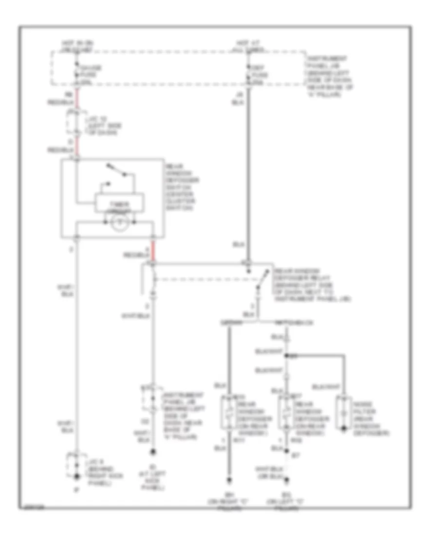
Forced Entry Wiring Diagram for Toyota Avalon XLS 2004
 https://portal-diagnostov.com/license.html
Automotive Electricians Portal FZCO
Automotive Electricians Portal FZCO
https://portal-diagnostov.com/license.html
https://portal-diagnostov.com/license.html
Automotive Electricians Portal FZCO
Automotive Electricians Portal FZCOList of elements for Forced Entry Wiring Diagram for Toyota Avalon XLS 2004:
- Bg (on left "c" pillar)
- Bh (on right "c" pillar)
- Def fuse 30a
- Gauge fuse 10a
- Hatchback
- Hot at all times
- Hot in on or start
- Id (at left kick panel)
- Instrument panel j/b (behind left side of dash, near base of "a" pillar)
- J/c 12 (left side of dash)
- J/c 9 (behind right kick panel)
- Noise filter (rear window defogger)
- R10
- R11
- R17
- R18
- Rear window defogger (on rear window)
- Rear window defogger relay (behind left side of dash, next to instrument panel j/b)
- Rear window defogger switch (center cluster switch)
- Sedan
- Timer circuit
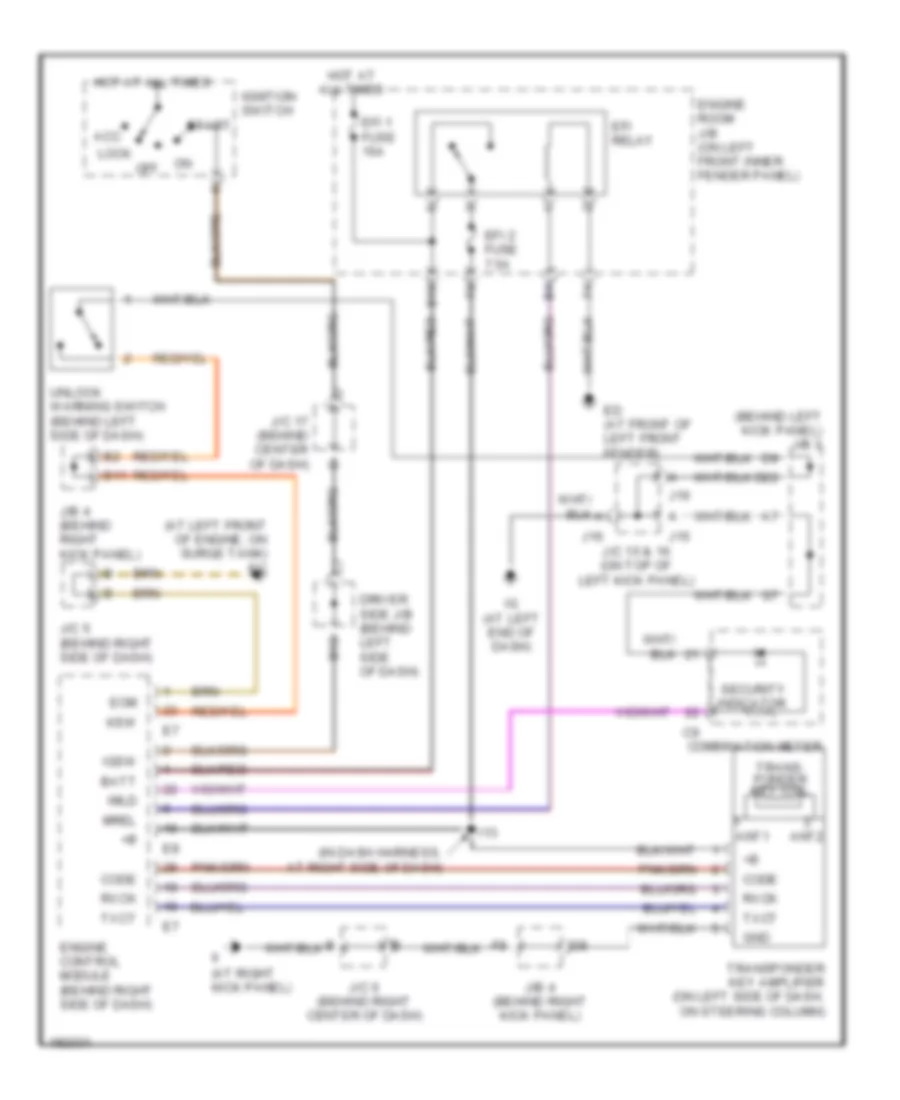
Immobilizer Wiring Diagram for Toyota Avalon XLS 2004
 https://portal-diagnostov.com/license.html
Automotive Electricians Portal FZCO
Automotive Electricians Portal FZCO
https://portal-diagnostov.com/license.html
https://portal-diagnostov.com/license.html
Automotive Electricians Portal FZCO
Automotive Electricians Portal FZCOList of elements for Immobilizer Wiring Diagram for Toyota Avalon XLS 2004:
- (at left front of engine, on surge tank) ec
- (at right kick panel)
- (behind left kick panel) j/b 3
- (in dash harness, at right side of dash)
- Acc
- Ant1
- Ant2
- B10
- B11
- B12
- Batt
- Code
- Combination meter
- D22
- Driver side j/b (behind left side of dash)
- Ed (at front of left front fender)
- Efi 1 fuse 15a
- Efi 2 fuse 7.5a
- Efi relay
- Engine control module (behind right side of dash)
- Engine room j/b (on left front inner fender panel)
- Eom
- Gnd
- Hot at all times
- I13
- Ig (at left end of dash)
- Ignition switch
- Igsw
- Imld
- J/b 4 (behind right kick panel)
- J/c 15 & 16 (on top of left kick panel)
- J/c 17 (behind center of dash)
- J/c 5 (behind right side of dash)
- J/c 6 (behind right center of dash)
- J15
- J16
- Ksw
- Lock
- Mrel
- Off
- Rxck
- Security indicator
- Start
- Trans- ponder key coil
- Transponder key amplifier (on left side of dash, on steering column)
- Txct
- Unlock warning switch (behind left side of dash)
BODY CONTROL MODULES
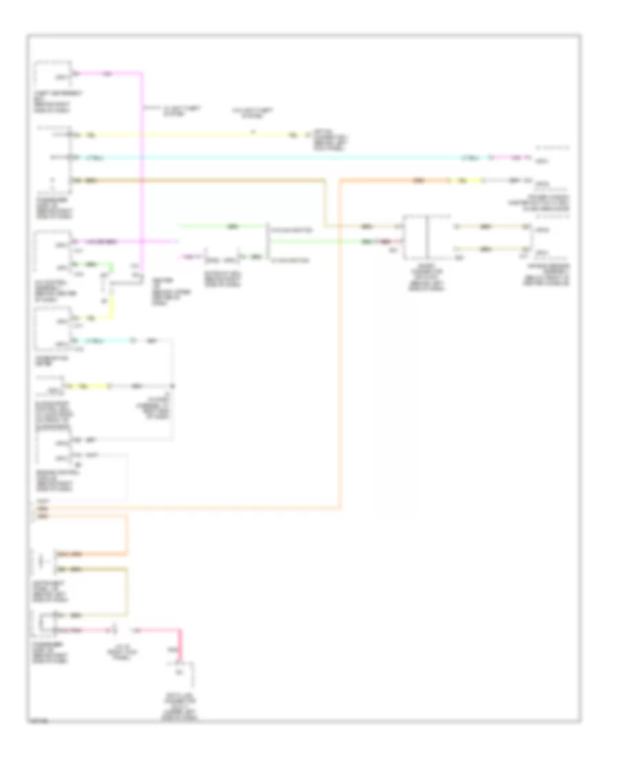
Body Control Modules Wiring Diagram (1 of 2) for Toyota Avalon XLS 2004
 https://portal-diagnostov.com/license.html
Automotive Electricians Portal FZCO
Automotive Electricians Portal FZCO
https://portal-diagnostov.com/license.html
https://portal-diagnostov.com/license.html
Automotive Electricians Portal FZCO
Automotive Electricians Portal FZCOList of elements for Body Control Modules Wiring Diagram (1 of 2) for Toyota Avalon XLS 2004:
- A/c control assembly (behind center of dash)
- A10
- A11
- A12
- A17
- Air bag sensor assembly (below front of center console)
- C11
- C12
- Center j/b (behind upper center of dash)
- Combination meter
- Data link connector (dlc) 3 (under left side of dash)
- E12
- Engine control module (behind right side of dash)
- Gateway ecu (behind right side of dash)
- I8 (in dash harness, at right end of dash)
- Instrument panel j/b (behind left side of dash)
- J/c 16 (right kick panel)
- J12
- Mpd1
- Mpd2
- Mpx+
- Mpx-
- Mpx1
- Mpx2
- Option connector 1 (behind left kick panel)
- Passenger side j/b (behind right side of dash)
- Pnk
- Power window master switch w/ ecu (in driver's door)
- Red
- S30
- S31
- Short connector s30 & s31 (behind left side of dash)
- Sil
- Sliding roof control ecu (w/ moon roof) (on front of sliding roof)
- Theft deterrent ecu (behind right side of dash)
- W/ anti-theft system
- W/ navigation
- W/o anti-theft system
- W/o navigation
Body Control Modules Wiring Diagram (2 of 2) for Toyota Avalon XLS 2004
 https://portal-diagnostov.com/license.html
Automotive Electricians Portal FZCO
Automotive Electricians Portal FZCO
https://portal-diagnostov.com/license.html
https://portal-diagnostov.com/license.html
Automotive Electricians Portal FZCO
Automotive Electricians Portal FZCOList of elements for Body Control Modules Wiring Diagram (2 of 2) for Toyota Avalon XLS 2004:
- (behind right center of dash) junction connector 18
- A/b
- A/d
- A12
- A13
- A15
- A17
- A19
- Abs
- Abs & ba & trac & vsc ecu (w/ traction control) (behind right side of dash)
- Abs actuator & ecu (w/o traction control) (on left rear of engine compt)
- Active light relay (column shift: behind right side of dash)
- B12
- B13
- B15
- B17
- B19
- B20
- Bat
- Center air bag sensor assembly (below center of dash)
- Cruise control ecu (column shift: behind left center of dash)
- D/g
- Data link connector 2 (behind left side of dash, on instrument panel j/b)
- Data link connector 3 (behind left side of dash, on instrument panel j/b)
- Driver side j/b (behind left side of dash)
- Ec (at left front of engine, on surge tank)
- Engine control module (behind right side of dash)
- H15
- H17
- Hot at all times
- I10
- I4 (in dash harness, at left kick panel)
- J/b 3 (behind left kick panel)
- J/b 4 (behind right kick panel)
- Junction connector 5 (behind right side of dash)
- Junction connector 7 (behind right side of dash)
- Junction connector 9 (on top of right kick panel)
- Junction connector 9 (on top of right kick panel)
- Multi display
- Obd ii fuse 7.5a
- Sil
- Translate ecu (behind right side of dash)
- W/ navigation
- W/ traction control
- W/o navigation
- W/o traction control
COMPUTER DATA LINES
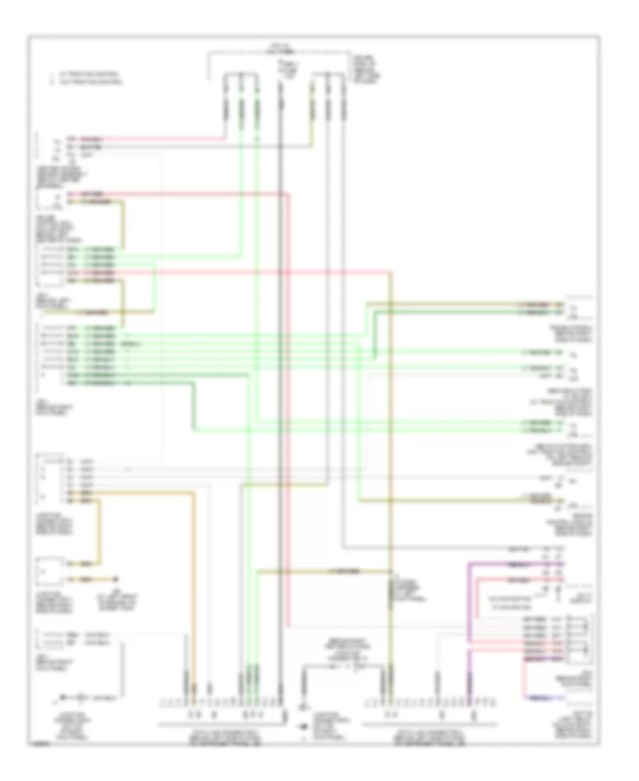
Computer Data Lines Wiring Diagram for Toyota Avalon XLS 2004
 https://portal-diagnostov.com/license.html
Automotive Electricians Portal FZCO
Automotive Electricians Portal FZCO
https://portal-diagnostov.com/license.html
https://portal-diagnostov.com/license.html
Automotive Electricians Portal FZCO
Automotive Electricians Portal FZCOList of elements for Computer Data Lines Wiring Diagram for Toyota Avalon XLS 2004:
- (below center of dash) center air bag sensor assembly
- (floor shift: behind right side of dash)
- A/b
- A/d
- A12
- A13
- A15
- A17
- A19
- Abs
- Abs & ba & trac & vsc ecu (w/ traction control) (behind right side of dash)
- Abs actuator & ecu (w/o traction control) (on left rear of engine compt)
- Active light relay (column shift: behind left side of dash)
- B12
- B13
- B15
- B17
- B19
- B20
- Bat
- Body ecu (behind left side of dash)
- Cruise control ecu (behind left center of dash)
- D/g
- Data link connector 2 (behind left side of dash, on instrument panel j/b)
- Data link connector 3 (behind left side of dash, on instrument panel j/b)
- Driver door ecu (in driver's door)
- Driver side j/b (behind left side of dash)
- Ec (at left front of engine, on surge tank)
- Engine control module (behind right side of dash)
- Front passenger door ecu (in right front door)
- H15
- H17
- Hot at all times
- I10
- I4 (in dash harness, at left kick panel)
- J/b 3 (behind left kick panel)
- J/b 4 (behind right kick panel)
- Junction connector 18 (behind right center of dash)
- Junction connector 5 (behind right side of dash)
- Junction connector 7 (behind right side of dash)
- Junction connector 9 (on top of right kick panel)
- Mpx1
- Mpx2
- Mpx3
- Mpx4
- Multi display
- Obd ii fuse 7.5a
- P21
- Power seat ecu (under driver's seat)
- Sil
- Theft deterrent ecu (behind right side of dash)
- Translate ecu (behind right side of dash)
- W/ navigation
- W/ traction control
- W/o navigation
- W/o traction control
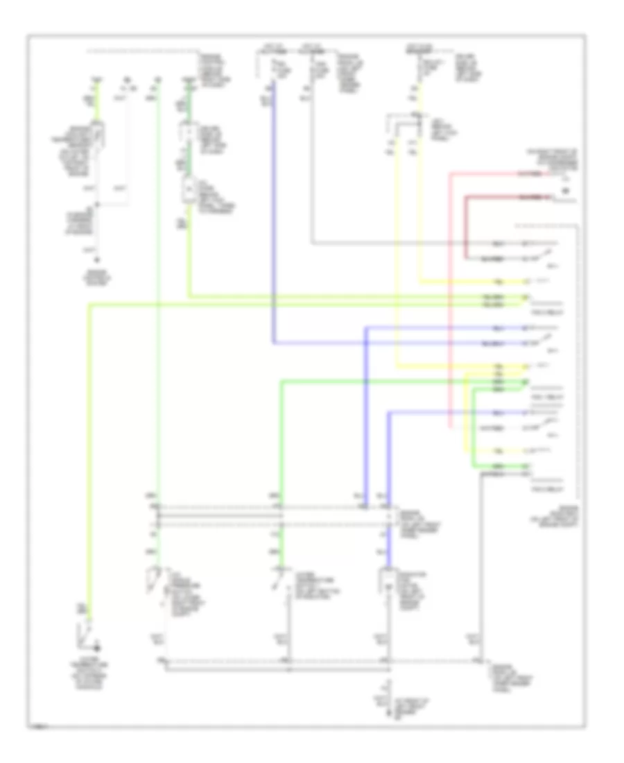
COOLING FAN
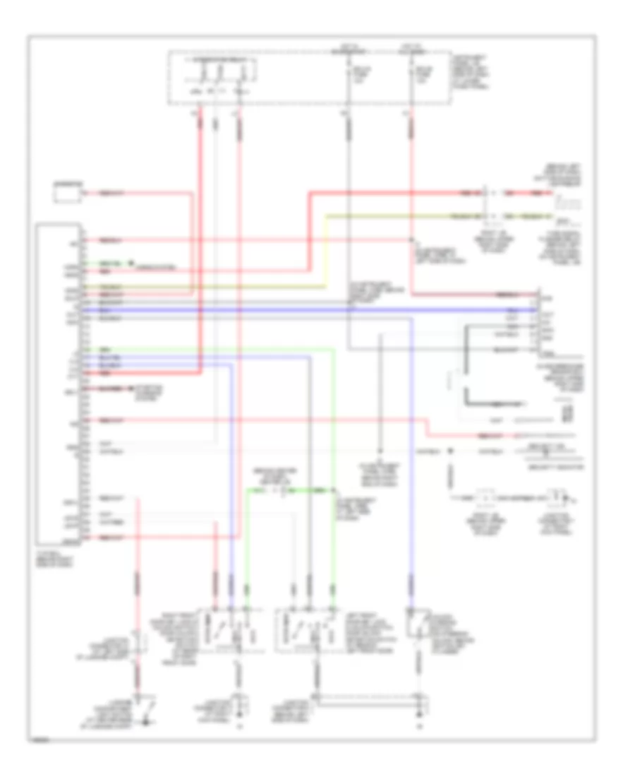
Cooling Fan Wiring Diagram for Toyota Avalon XLS 2004
 https://portal-diagnostov.com/license.html
Automotive Electricians Portal FZCO
Automotive Electricians Portal FZCO
https://portal-diagnostov.com/license.html
https://portal-diagnostov.com/license.html
Automotive Electricians Portal FZCO
Automotive Electricians Portal FZCOList of elements for Cooling Fan Wiring Diagram for Toyota Avalon XLS 2004:
- (at front of left front fender) ed
- (on right front of engine compt) a/c condenser fan motor
- A/c diode (behind left kick panel, taped to harness)
- A/c single pressure switch (on lower right front of engine compt)
- Acmg
- Cds fuse 30a
- Driver side j/b (behind left side of dash)
- E2 (in engine harness, at front of engine)
- Ecu-ig 1 fuse 5a
- Engine control module (behind right side of dash) e7
- Engine controls system
- Engine coolant temperature sensor (on water outlet, on
- Engine room j/b (on left front inner fender panel)
- Engine room r/b 3 (on left front of engine compt)
- F12
- Fan 1 relay
- Fan 2 relay
- Fan 3 relay
- H11
- Hot at all times
- Hot in on or start
- J/b 3 (behind left kick panel)
- Radiator fan motor (on left front of engine compt)
- Rdi fuse 30a
- Thw
- Top right front of engine)
- Water temperature switch 1 (on left bottom of radiator)
- Water temperature switch 2 (on top rear of intake manifold)
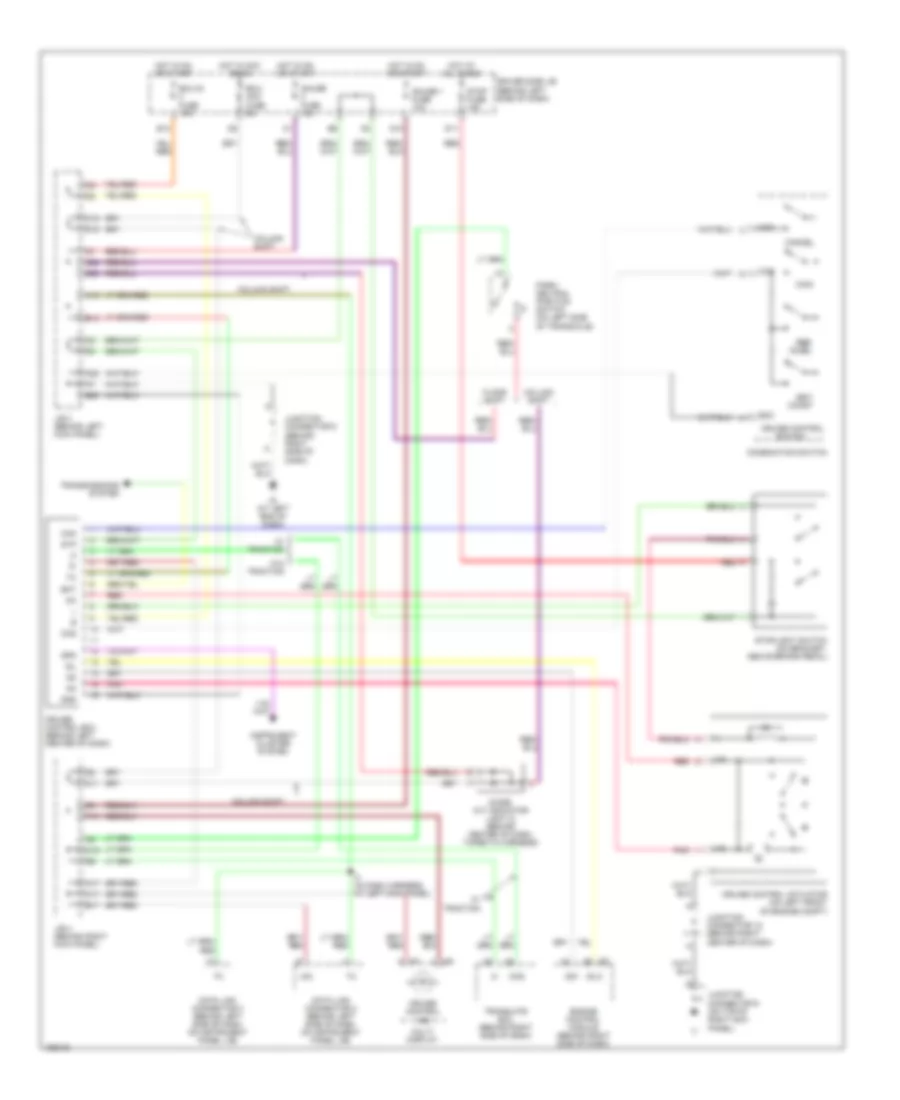
CRUISE CONTROL
Cruise Control Wiring Diagram for Toyota Avalon XLS 2004
 https://portal-diagnostov.com/license.html
Automotive Electricians Portal FZCO
Automotive Electricians Portal FZCO
https://portal-diagnostov.com/license.html
https://portal-diagnostov.com/license.html
Automotive Electricians Portal FZCO
Automotive Electricians Portal FZCOList of elements for Cruise Control Wiring Diagram for Toyota Avalon XLS 2004:
- A/d
- A13
- A17
- A20
- B13
- B17
- B20
- C11
- C15
- C19
- C20
- Can
- Cancel
- Ccs
- Column shift
- Combination switch
- Cruise control
- Cruise control actuator (on left front of engine compt)
- Cruise control ecu (behind left center of dash)
- Cruise control ind
- D10
- D11
- D15
- D20
- Data link connector 2 (behind left side of dash, on instrument panel j/b)
- Data link connector 3 (behind left side of dash, on instrument panel j/b)
- Diode (a/t indicator light 2) (behind center of dash, taped to harness)
- Driver side j/b (behind left side of dash)
- Ecc
- Ect
- Ecu- acc fuse 5a
- Ecu-ig fuse 10a
- Engine control module (behind right side of dash)
- F13
- Floor shift
- Gauge 1 fuse 10a
- Gauge fuse 10a
- Gnd
- H17
- Hot at all times
- Hot in acc or on
- Hot in on or start
- I4 (in dash harness, at left kick panel)
- Idl
- Idlo
- Ig (at left end of dash)
- Instrument cluster system
- J/b 3 (behind left kick panel)
- J/b 4 (behind right kick panel)
- Junction connector 18 (behind right center of dash)
- Junction connector 5 (behind right side of dash)
- Junction connector 9 (on top of right kick panel)
- Main
- Multi display
- Od1
- Park/ neutral position switch (on left side of transaxle)
- Pnk
- Red
- Res/ accel
- Set/ coast
- Spd
- Stop fuse 15a
- Stoplight switch (on bracket, above brake pedal)
- Stp
- Switch
- Translate ecu (behind right side of dash)
- Transmissions system
- W/ traction
- W/o traction
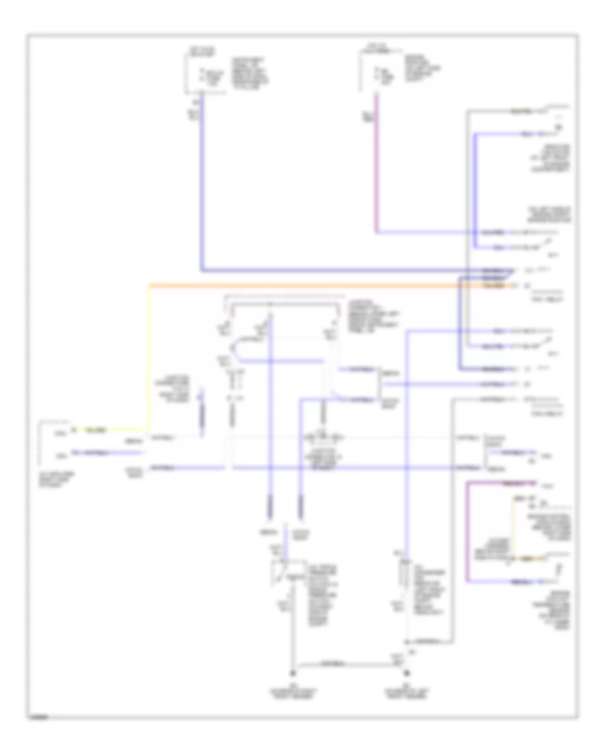
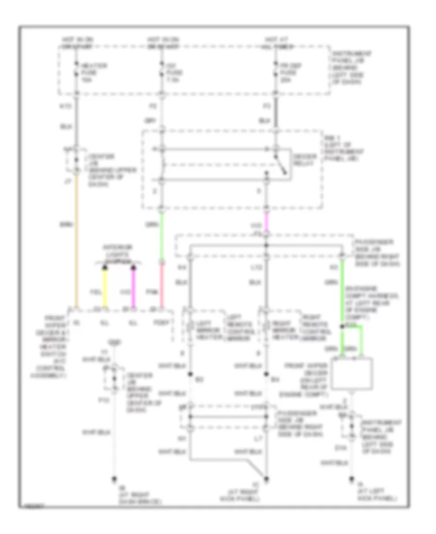
DEFOGGERS
Rear Defogger & Heated Mirrors Wiring Diagram for Toyota Avalon XLS 2004
 https://portal-diagnostov.com/license.html
Automotive Electricians Portal FZCO
Automotive Electricians Portal FZCO
https://portal-diagnostov.com/license.html
https://portal-diagnostov.com/license.html
Automotive Electricians Portal FZCO
Automotive Electricians Portal FZCOList of elements for Rear Defogger & Heated Mirrors Wiring Diagram for Toyota Avalon XLS 2004:
- (in engine compt harness, at left rear of engine compt) e13
- Center j/b (behind upper center of dash)
- D14
- Deicer relay
- F13
- Fdef
- Fr def fuse 20a
- Front wiper deicer & mirror heater switch (a/c control assembly)
- Front wiper deicer (on left rear of engine compt)
- Gnd
- Heater fuse 10a
- Hot at all times
- Hot in on or start
- Ia (at left kick panel)
- Ib (at right dash brace)
- Ic (at right kick panel)
- Ig1 fuse 7.5a
- Ill
- Instrument panel j/b (behind left side of dash)
- Interior lights system
- K13
- L10
- L12
- Left mirror heater
- Left remote control mirror
- Passenger side j/b (behind right side of dash)
- Pnk
- R/b 1 (left of instrument panel j/b)
- Right mirror heater
- Right remote control mirror
ENGINE PERFORMANCE
3.0L
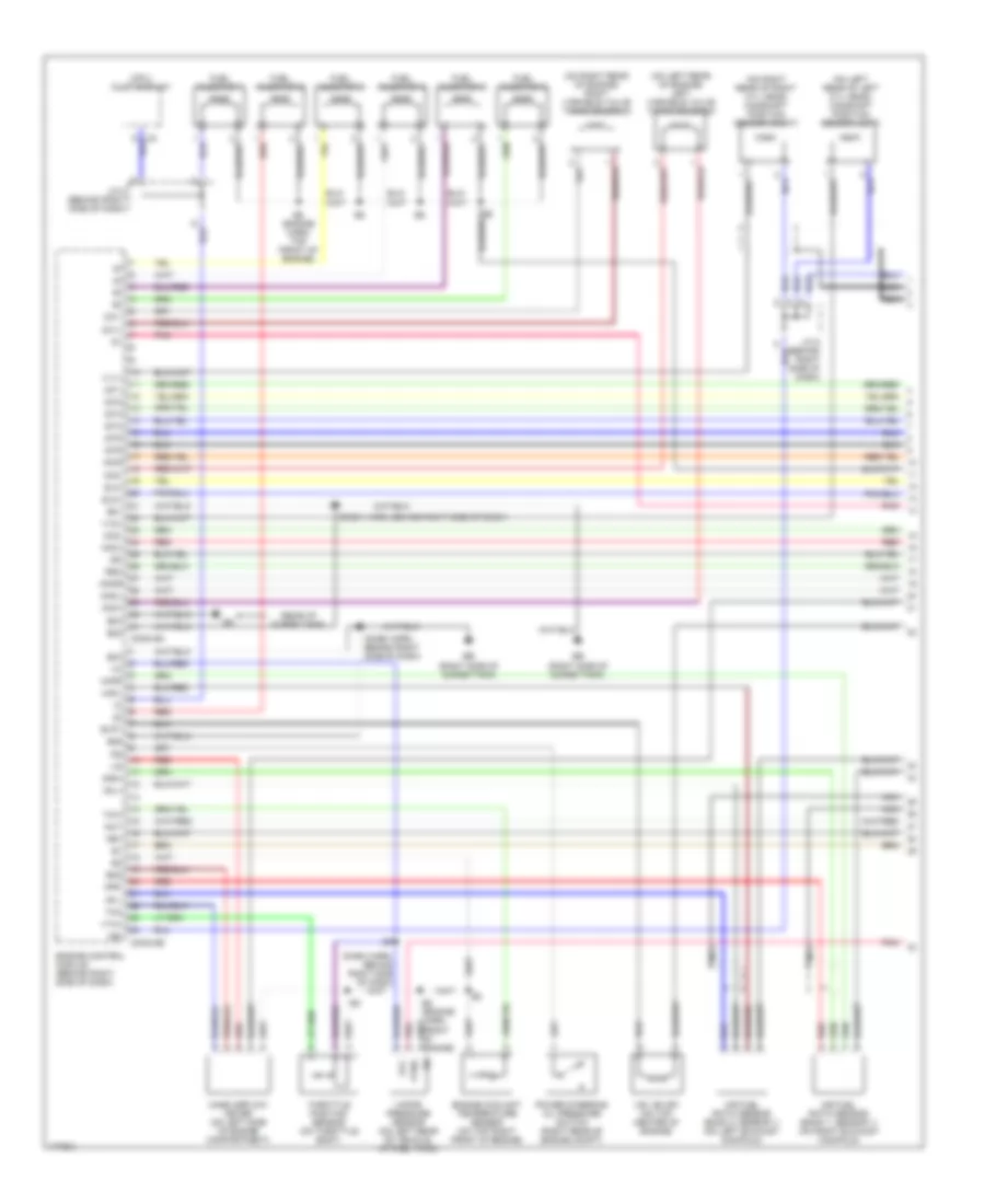
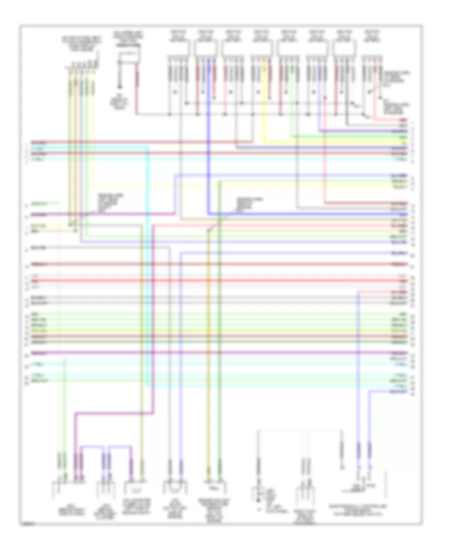
3.0L, Engine Performance Wiring Diagram (1 of 4) for Toyota Avalon XLS 2004
 https://portal-diagnostov.com/license.html
Automotive Electricians Portal FZCO
Automotive Electricians Portal FZCO
https://portal-diagnostov.com/license.html
https://portal-diagnostov.com/license.html
Automotive Electricians Portal FZCO
Automotive Electricians Portal FZCOList of elements for 3.0L, Engine Performance Wiring Diagram (1 of 4) for Toyota Avalon XLS 2004:
- (cpu) multi-display
- (dash harn, behind right side of dash)
- (on left rear of engine) left variable valve timing solenoid
- (on left rear of left cyl head) camshaft position sensor (left)
- (on right rear of engine) right variable valve timing solenoid
- (on right rear of right cyl head) camshaft position sensor (right)
- (rear of surge tank)
- Aci1
- Acis
- Afl+
- Afl-
- Afr+
- Afr-
- Air fuel ratio sensor (bank 1, sensor 1) (on right exhaust manifold)
- Air fuel ratio sensor (bank 2, sensor 1) (on left exhaust manifold)
- Conn e4
- Conn e5
- E01
- E02
- E03
- E04
- E05
- E2g
- E5 (engine harn, top front of engine)
- Eb (right side of surge tank)
- Engine control module (behind right side of dash)
- Engine coolant temperature sensor (on top right front of engine)
- Evp1
- Fuel injector 1
- Fuel injector 2
- Fuel injector 3
- Fuel injector 4
- Fuel injector 5
- Fuel injector 6
- Hafl
- Hafr
- I22
- I23
- Igf
- Igt1
- Igt2
- Igt3
- Igt4
- Igt5
- Igt6
- J/c 8 (behind right side of dash)
- Knkl
- Knkr
- Mass airflow meter (on left side of engine compartment)
- Nc2+
- Nc2-
- Nca
- Ne+
- Ne-
- Oc1+
- Oc1-
- Oc2+
- Oc2-
- Pnk
- Power steering oil pressure switch (right rear of engine compt)
- Ptnk
- Red
- Rso
- Sln+
- Sln-
- Tha
- Throttle position sensor (on throttle body)
- Thw
- Vapor pressure sensor (on left rear of vehicle, at fuel tank)
- Vcc
- Vsv (evap) (on top center of engine)
- Vta1
- Vv1+
- Vv2+
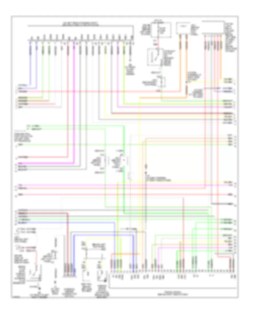
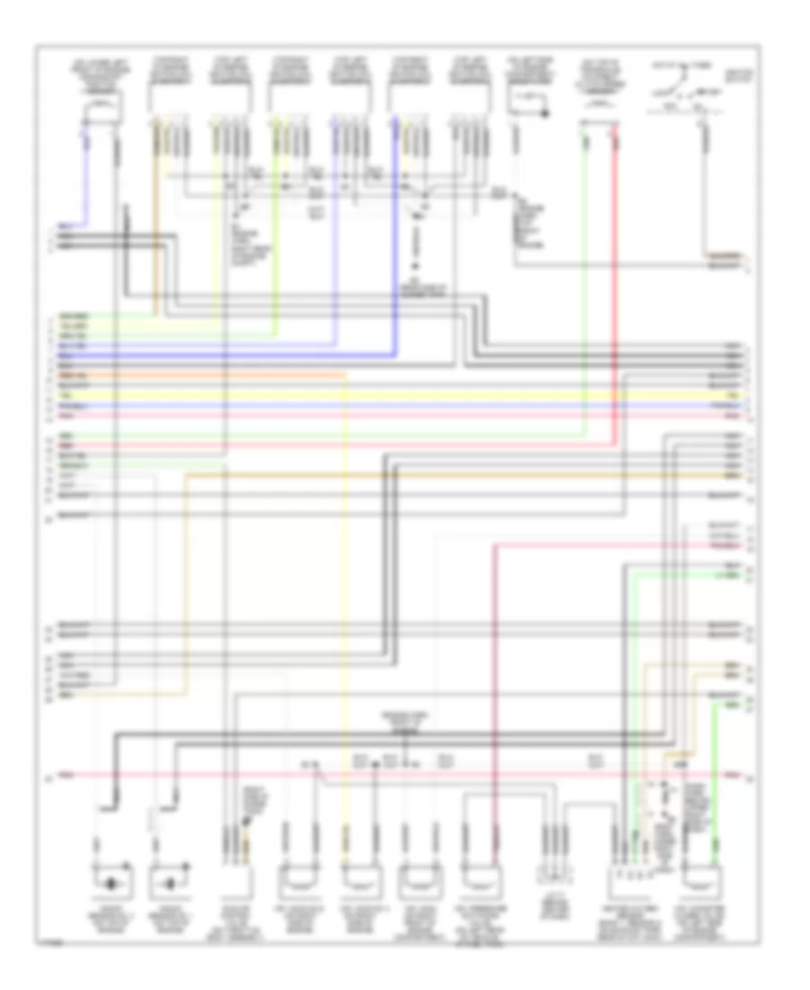
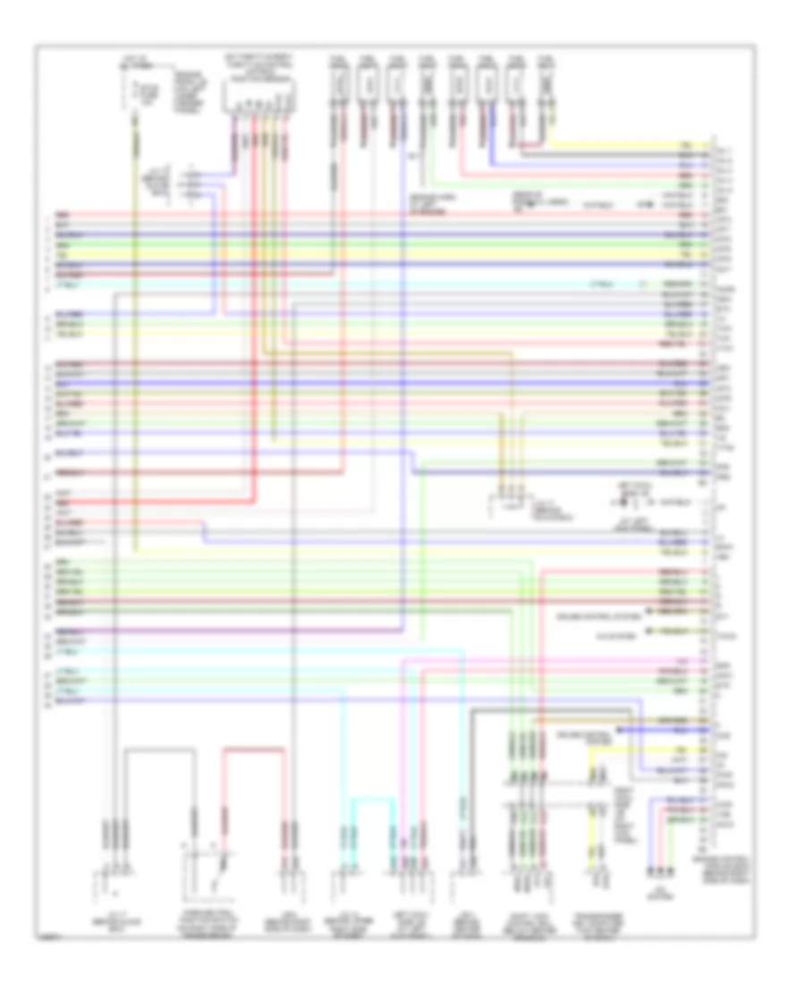
3.0L, Engine Performance Wiring Diagram (2 of 4) for Toyota Avalon XLS 2004
 https://portal-diagnostov.com/license.html
Automotive Electricians Portal FZCO
Automotive Electricians Portal FZCO
https://portal-diagnostov.com/license.html
https://portal-diagnostov.com/license.html
Automotive Electricians Portal FZCO
Automotive Electricians Portal FZCOList of elements for 3.0L, Engine Performance Wiring Diagram (2 of 4) for Toyota Avalon XLS 2004:
- (dash harn, behind upper right side of dash)
- (engine harn, front of engine)
- (on left side of engine compartment) noise filter
- (on lower left front of engine) crankshaft position sensor
- (on right side of engine)
- (on top of transaxle) o/d direct clutch speed sensor
- (rear side of surge tank)
- (right side of surge tank) eb
- (top left of engine) ignition coil & igniter 2
- (top left of engine) ignition coil & igniter 4
- (top left of engine) ignition coil & igniter 6
- (top right of engine) ignition coil & igniter 1
- (top right of engine) ignition coil & igniter 3
- (top right of engine) ignition coil & igniter 5
- Acc
- B5 (body harn, under right side of dash)
- E4 (engine harn, right rear of engine compt)
- Heated oxygen sensor (bank 1, sensor 2) (on exhaust pipe, rear of cat conv)
- Hot at all times
- I14
- Idle air control valve (on throttle body assembly)
- Ignition switch
- J/c 17 (behind center of dash)
- Knock sensor no. 1 (on top of engine)
- Knock sensor no. 2 (on top of engine)
- Lock
- Nca
- Pnk
- Red
- Start
- Top front of engine)
- Vsv (acis no.1)
- Vsv (acis no.2) (on right side of engine)
- Vsv (acm) (on right front of engine compartment)
- Vsv (canister closed valve) (on left side of engine compartment)
- Vsv (pressure switching valve) (on left rear of vehicle, at fuel tank)
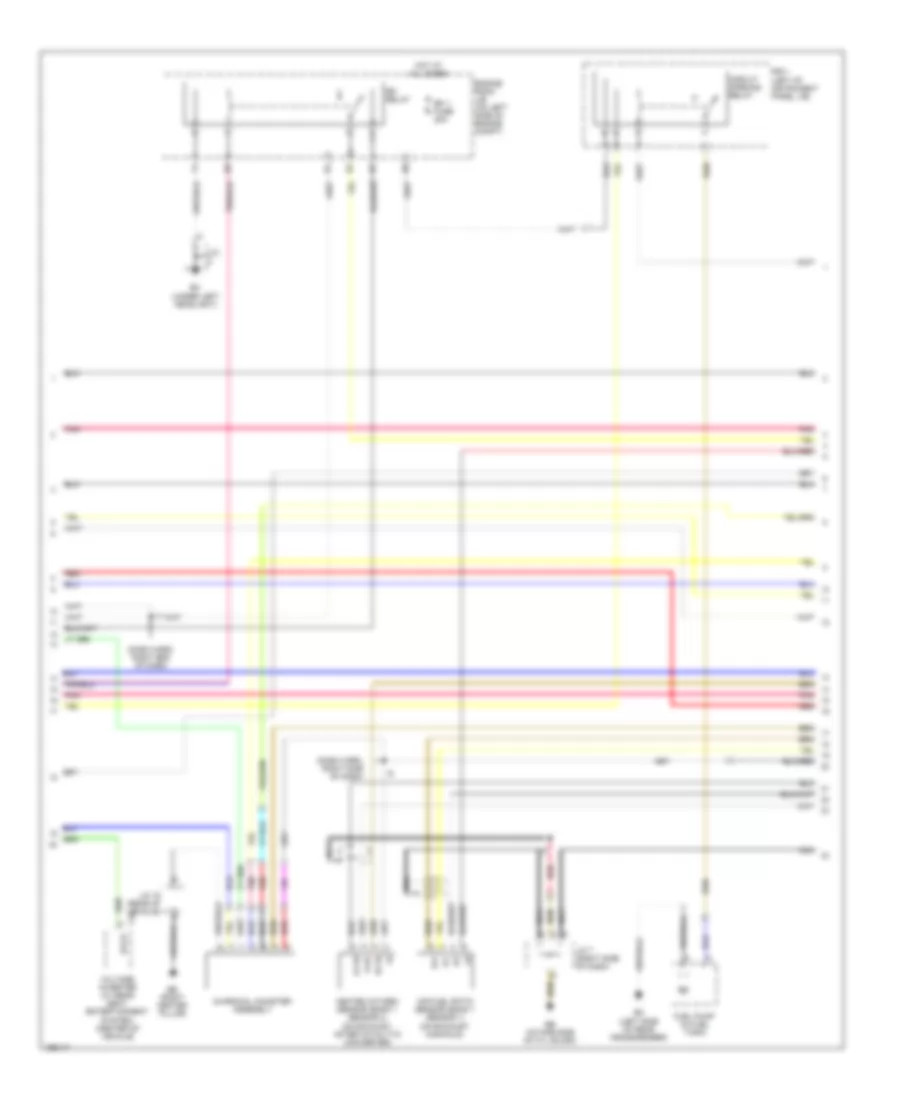
3.0L, Engine Performance Wiring Diagram (3 of 4) for Toyota Avalon XLS 2004
 https://portal-diagnostov.com/license.html
Automotive Electricians Portal FZCO
Automotive Electricians Portal FZCO
https://portal-diagnostov.com/license.html
https://portal-diagnostov.com/license.html
Automotive Electricians Portal FZCO
Automotive Electricians Portal FZCOList of elements for 3.0L, Engine Performance Wiring Diagram (3 of 4) for Toyota Avalon XLS 2004:
- (dash harn, right end of dash)
- (dash harn, right side of dash)
- Af+
- Af-
- Air fuel ratio sensor (bank 1 sensor 1) (on exhaust manifold)
- Bb (right center pillar)
- Bc (left side of rear crossmember)
- Charcoal canister assembly
- Circuit opening relay
- Ee (intake side of cyl block)
- Efi 1 fuse 20a
- Efi relay
- Eh (under left headlight)
- Engine room j/b (on left side of engine compt)
- Fuel pump (in fuel tank)
- Heated oxygen sensor (bank 1 sensor 2) (on exhaust, after catalytic converter)
- Hot at all times
- Ht1b
- J/c
- J/c 19 (rear of vehicle)
- J/c 7 (right side of dash)
- Nca
- O1b-
- Ox1b
- Pnk
- R/b 1 (left of instrument panel j/b)
- Red
- V15 excd
- Voltage inverter (w/ rear seat entertainment system) (center of vehicle)
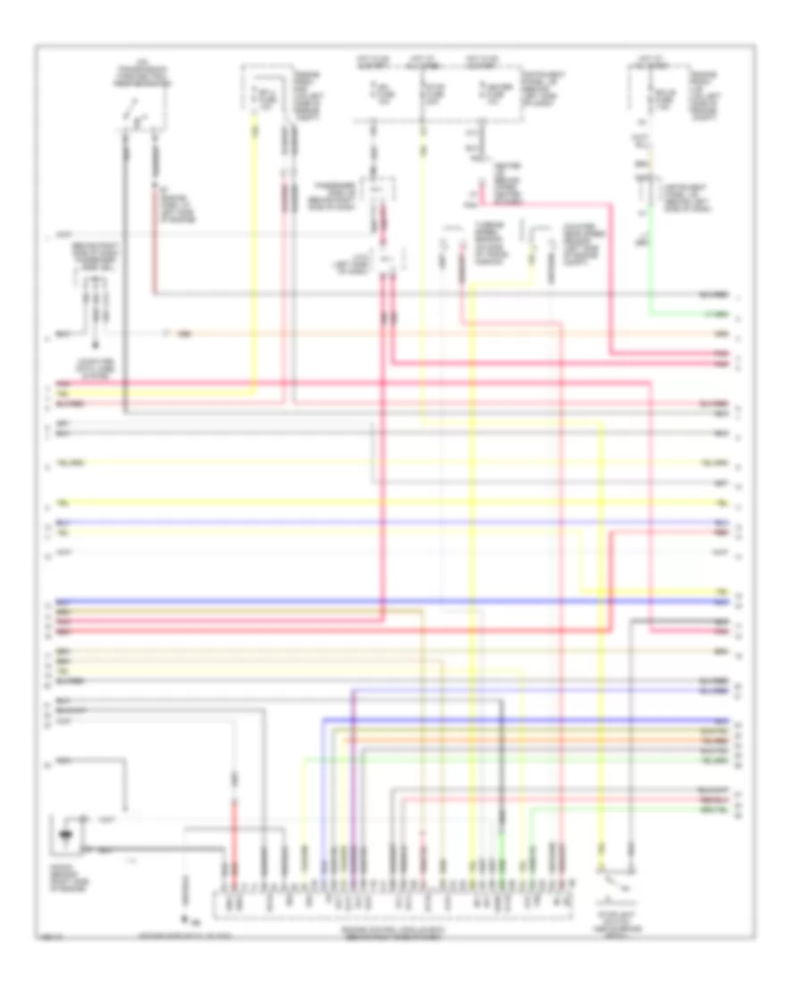
3.0L, Engine Performance Wiring Diagram (4 of 4) for Toyota Avalon XLS 2004
 https://portal-diagnostov.com/license.html
Automotive Electricians Portal FZCO
Automotive Electricians Portal FZCO
https://portal-diagnostov.com/license.html
https://portal-diagnostov.com/license.html
Automotive Electricians Portal FZCO
Automotive Electricians Portal FZCOList of elements for 3.0L, Engine Performance Wiring Diagram (4 of 4) for Toyota Avalon XLS 2004:
- (behind right side of dash) passenger side j/b
- (intake side of cyl block)
- (on transmission) park/neutral position switch
- A1a+
- A1a-
- Center j/b (behind upper center of dash)
- Computer data lines system
- Counter gear speed sensor (left side of engine compt)
- Dsl
- E04
- E7 (engine harn, at left side of engine)
- Ecu-b fuse 7.5a
- Efi 2 fuse 10a
- Eknk
- Engine control module (ecm) (behind right side of dash)
- Engine room j/b (on left side of engine compt)
- Engine room r/b (on left side of engine compt)
- G10
- Ha1a
- Heater fuse 10a
- Hot at all times
- Hot in on & start
- Ht1b
- Ign fuse 10a
- Instrument panel j/b (behind left side of dash)
- J/c 6 (left side of dash)
- K13
- Knk1
- Knk2
- Knock sensor (right side of engine)
- L11
- Nc+
- Nc-
- Nca
- Nt+
- Nt-
- Ox1b
- P/n
- Passenger side j/b (behind right side of dash)
- Pnk
- Red
- Sl1+
- Sl1-
- Sl2+
- Sl2-
- Slt+
- Slt-
- Stop fuse 20a
- Stoplight switch (above brake pedal)
- Th0
- Turbine speed sensor (on side of trans- mission)
EXTERIOR LIGHTS
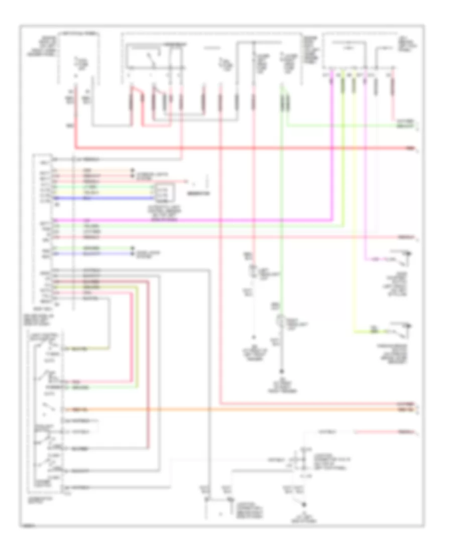
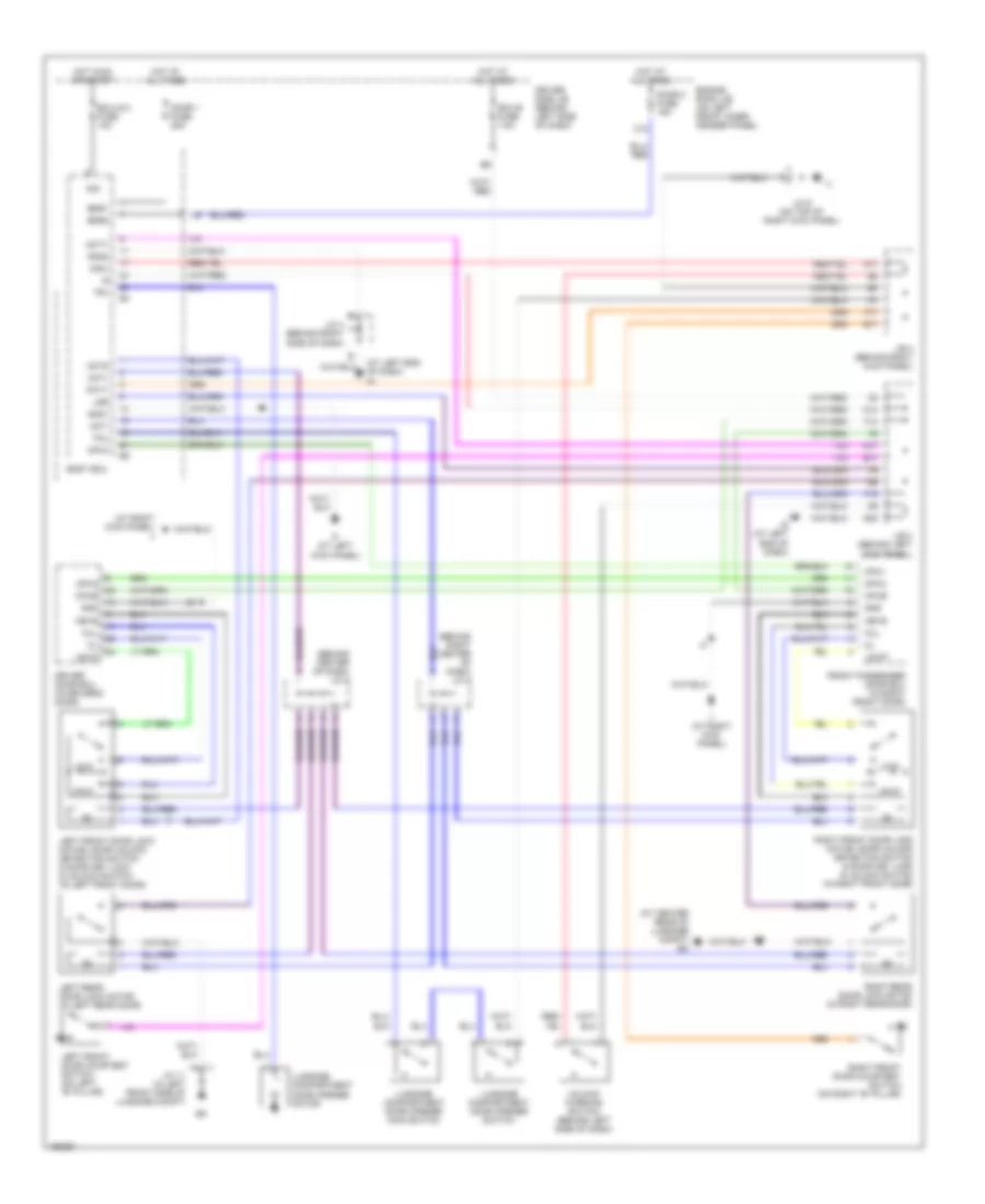
Back-up Lamps Wiring Diagram, with Column Shift for Toyota Avalon XLS 2004
 https://portal-diagnostov.com/license.html
Automotive Electricians Portal FZCO
Automotive Electricians Portal FZCO
https://portal-diagnostov.com/license.html
https://portal-diagnostov.com/license.html
Automotive Electricians Portal FZCO
Automotive Electricians Portal FZCOList of elements for Back-up Lamps Wiring Diagram, with Column Shift for Toyota Avalon XLS 2004:
- (engine harn, at rear of engine)
- (engine harn, left rear of engine compt)
- (engine harn, rear of engine) e10
- (on air intake, next to air cleaner box) mass airflow (maf) meter
- (on upper left side of engine) (ignition) noise filter
- 2nd strt
- D10
- E10
- E11
- E11 (engine harn, left side of engine)
- E13
- E18
- E2g
- Ec (rear of right cyl head)
- Electronically controlled transmission pattern select switch
- Engine coolant temperature sensor (on top front of engine)
- Ignition coil & igniter 1
- Ignition coil & igniter 2
- Ignition coil & igniter 3
- Ignition coil & igniter 4
- Ignition coil & igniter 5
- Ignition coil & igniter 6
- Ignition coil & igniter 7
- Ignition coil & igniter 8
- J/b 5 (behind instrument cluster)
- J/b 6 (behind right side of dash)
- Left cowl side j/b (at left kick panel)
- M10
- Pwr
- Red
- Right cowl side j/b (at right kick panel)
- Tha
- Vsv (canister closed valve) (left side of engine compt)
- Vsv (evap) (on top left side of engine)
Back-up Lamps Wiring Diagram, with Floor Shift for Toyota Avalon XLS 2004
 https://portal-diagnostov.com/license.html
Automotive Electricians Portal FZCO
Automotive Electricians Portal FZCO
https://portal-diagnostov.com/license.html
https://portal-diagnostov.com/license.html
Automotive Electricians Portal FZCO
Automotive Electricians Portal FZCOList of elements for Back-up Lamps Wiring Diagram, with Floor Shift for Toyota Avalon XLS 2004:
- (at left kick panel)
- (engine harn, at left of engine)
- (on right side of transmission)
- (on throttle body) throttle control motor & position sensor
- (rear of right cyl head)
- +bm
- A/c system
- A/cs
- Accr
- Acld
- At4
- Atc
- C12
- Ccs
- Ccv
- Cruise control system
- D14
- D15
- E01
- E02
- E10
- E11
- E24
- E28
- E2g
- Efii
- Efio
- Engine control module (ecm) (behind right side of dash)
- Engine room j/b (on left inner fender panel)
- Etcs fuse 10a
- Fpr
- Fuel inj 1
- Fuel inj 2
- Fuel inj 3
- Fuel inj 4
- Fuel inj 5
- Fuel inj 6
- Fuel inj 7
- Fuel inj 8
- Hot at all times
- Igf1
- Igf2
- Igt1
- Igt2
- Igt3
- Igt5
- Igt6
- Igt7
- Igt8
- Imi
- Imo
- Inj 1
- Inj 2
- Inj 3
- Inj 4
- Inj 5
- J/b 4 (behind center of dash)
- J/b 6 (behind right side of dash)
- J/c 14 (behind upper right side of dash)
- J/c 17 (behind glove box)
- Left cowl side j/b
- Left cowl side j/b (at left kick panel)
- M15
- M16
- Mpx1
- Mpx2
- Nssd
- Nssl
- Nsw
- P/n
- P10
- P12
- P13
- P14
- Park/neutral position switch
- Prg
- Pwr
- Q66
- Q70
- Red
- Right cowl side j/b (at right kick panel)
- Shift lock control ecu (below center console)
- Snwi
- Spd
- St1
- Sta
- Stp
- Tha
- The
- Thw
- Thwo
- Transponder key computer (top center of dash)
- Vta1
- Vta2
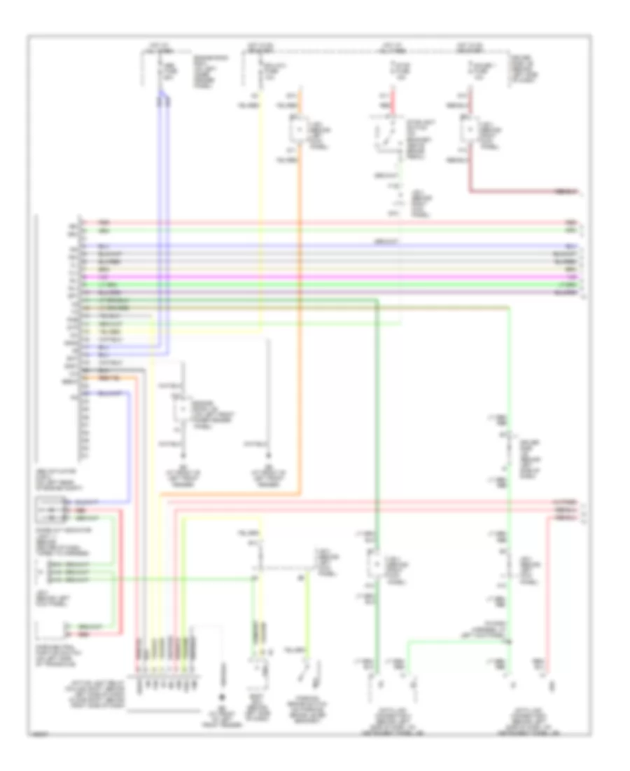
Exterior Lamps Wiring Diagram for Toyota Avalon XLS 2004
 https://portal-diagnostov.com/license.html
Automotive Electricians Portal FZCO
Automotive Electricians Portal FZCO
https://portal-diagnostov.com/license.html
https://portal-diagnostov.com/license.html
Automotive Electricians Portal FZCO
Automotive Electricians Portal FZCOList of elements for Exterior Lamps Wiring Diagram for Toyota Avalon XLS 2004:
- (at center rear of luggage compartment) bm
- (in body harness, at right front of luggage compt) b10
- (in right rear side of luggage compartment) j/c 12
- (in right rear side of luggage compt) j/c 13
- A11
- A21
- Alt fuse 120a
- B21
- B8 (in body harness, at right side of trunk lid)
- Body ecu
- C12
- Combination meter
- Combination switch
- D10
- D11
- Driver side j/b (behind left side of dash)
- Ed (at front of left front fender)
- Engine room j/b (on left front inner fender panel)
- F10
- F13
- Fusible link block (left side of engine compartment)
- Gauge 1 fuse 10a
- Haz fuse 15a
- Hazard switch off
- Head
- High mount stop light
- Hot at all times
- Hot in on or start
- Ig (at left end of dash)
- J/b 3 (behind left kick panel)
- J/b 4 (behind right kick panel)
- J/c 10 (in right front side of luggage compartment)
- J/c 10 (in right front side of luggage compt)
- J/c 12 (in right rear side of luggage compt)
- J/c 15 & 16 (on top of left kick j16 panel)
- J/c 15 & 16 (on top of left kick panel)
- J/c 17 (behind center of dash)
- J/c 5 (behind right side of dash)
- J/c 9 (on top of right kick panel)
- J15
- J16
- L10
- Left
- Left front park/ turn light
- Left license plate light
- Left rear combi- nation light
- Left rear combin- ation light
- Light control switch
- Light failure sensor (on right side of luggage compt)
- Multi- display
- Noise filter (stop light) (center front of luggage compt)
- Off
- Pnk
- R18
- R19
- Rear lights warning ind
- Red
- Right
- Right front park/ turn light
- Right license plate light
- Right rear combi- nation light
- Right rear combin- ation light
- Side
- Stop
- Stop fuse 15a
- Stoplight switch (on bracket, above brake pedal)
- Tail
- Tail fuse 10a
- Tail relay
- Trly
- Turn
- Turn fuse 7.5a
- Turn signal flasher relay (behind top left side of dash)
- Turn signal ind lights
- Turn signal switch
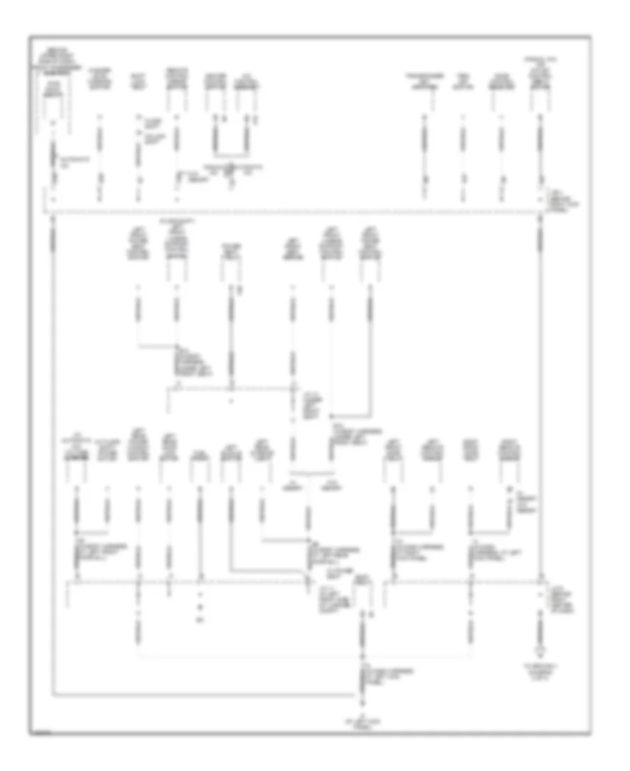
GROUND DISTRIBUTION
Ground Distribution Wiring Diagram (1 of 4) for Toyota Avalon XLS 2004
 https://portal-diagnostov.com/license.html
Automotive Electricians Portal FZCO
Automotive Electricians Portal FZCO
https://portal-diagnostov.com/license.html
https://portal-diagnostov.com/license.html
Automotive Electricians Portal FZCO
Automotive Electricians Portal FZCOList of elements for Ground Distribution Wiring Diagram (1 of 4) for Toyota Avalon XLS 2004:
- (at left rear of vehicle) junction connector 8 & 9
- (at left side of engine compartment)
- (behind left
- (canada)
- (on bracket, above brake pedal)
- (usa)
- (usa) tail relay
- A11
- A21
- B11
- B15
- B17
- B18
- B21
- B22
- B9 (in back door harness 2, at right side of back door)
- Bh (at left quarterpanel)
- Bi (at right quarterpanel)
- C14
- Center j/b
- Combination
- Combination meter
- Control
- D12
- D17
- Daytime running light relay (behind left side of dash)
- Ea (at front side of right fender)
- Eb (on left front suspension tower)
- Ehw
- Engine room r/b (integral to engine room j/b)
- Gauge fuse 10a
- Gnd
- H11
- H12
- H13
- Hazard fuse 10a
- Hazard switch
- Head
- High
- Hot at all times
- Hot in on or start
- I7 (in instrument panel harness, behind right side of dash)
- Instrument panel j/b (behind left side of dash)
- Interior lights system
- J/c
- J/c 8 & 9 (at left rear of vehicle)
- J/c 8 (at left rear of vehicle)
- Junction connector 11 (at left side of back door)
- Junction connector 2 (behind left side of dash)
- Junction connector 7 (at right kick panel)
- Left front combination light
- Left license plate light
- Left rear combination light
- Light
- Mounted
- Off
- Park
- Right front combination light
- Right j/b (behind upper right side of dash)
- Right license plate light
- Right r/b (integral to right j/b)
- Right rear combination light
- Side of dash)
- Stop
- Stop fuse 15a
- Stop light switch
- Stoplight
- Switch
- Tail
- Tail fuse 15a
- Turn
- Turn sig
- Turn signal flasher relay (behind left side of dash, on instrument panel j/b)
- Turn signal ind
- W/ wireless door lock
- W/o wireless door lock
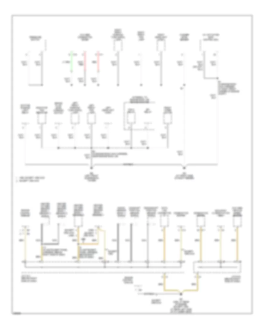
Ground Distribution Wiring Diagram (2 of 4) for Toyota Avalon XLS 2004
 https://portal-diagnostov.com/license.html
Automotive Electricians Portal FZCO
Automotive Electricians Portal FZCO
https://portal-diagnostov.com/license.html
https://portal-diagnostov.com/license.html
Automotive Electricians Portal FZCO
Automotive Electricians Portal FZCOList of elements for Ground Distribution Wiring Diagram (2 of 4) for Toyota Avalon XLS 2004:
- (behind upper right side of dash) front passenger side r/b 7
- (floor shift) left front lumbar support control switch
- (manual a/c) air outlet control servo motor
- (w/ automatic a/c) voltage inverter
- (w/ floor shift) power outlet
- A/c control assembly
- A15
- Automatic a/c
- B1 (in body harness, at left front door sill)
- B12 (in body harness, under left front seat)
- B6 (in body harness, at left rear door sill)
- Body ecu
- C20
- Column shift
- D20
- D21
- Door control receiver
- F20
- Floor shift
- Fuel pump
- Heater control switch
- I21 (in dash harness, at right kick panel)
- I3 (in dash harness, at left kick panel)
- I5 (in dash harness, at left kick panel)
- If (at left kick panel)
- J/b 4 (behind right kick panel)
- J/c 11 (in left front side of luggage compt)
- J/c 14 (under left front seat)
- J/c 6 (behind right center of dash)
- Left buckle switch
- Left front door ecu
- Left front lumbar support control switch
- Left front power seat control switch
- Left front seat heater
- Left rear door lock motor
- Left rear interior light
- Left rear power window control switch
- Left remote control mirror
- Manual a/c
- P20
- Power seat ecu
- Pwr point relay
- Remote control mirror switch
- Right front door ecu
- Right remote control mirror
- Shift lock ecu
- To ground ii (diagram 3 of 4)
- Trac off switch
- Transponder key amplifier
- W/ memory
- W/ power seat
- W/o memory
- Washer level warning switch
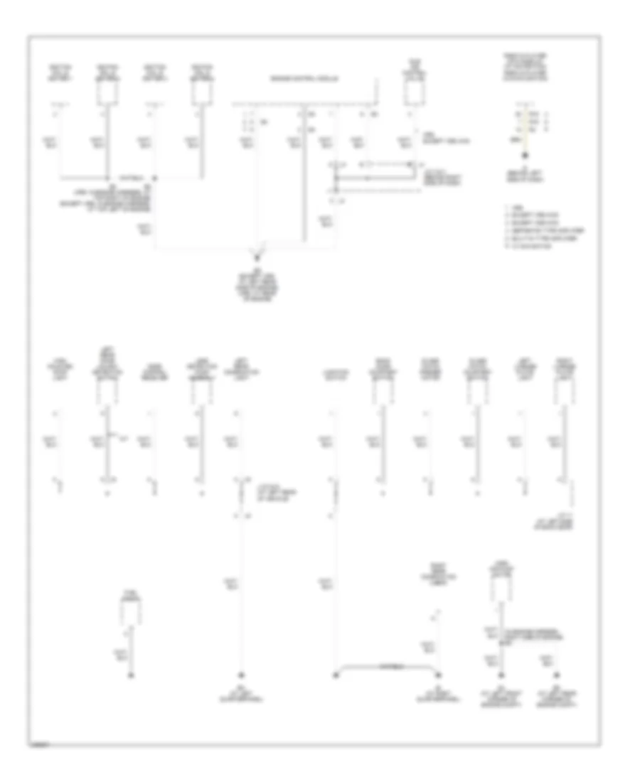
Ground Distribution Wiring Diagram (3 of 4) for Toyota Avalon XLS 2004
 https://portal-diagnostov.com/license.html
Automotive Electricians Portal FZCO
Automotive Electricians Portal FZCO
https://portal-diagnostov.com/license.html
https://portal-diagnostov.com/license.html
Automotive Electricians Portal FZCO
Automotive Electricians Portal FZCOList of elements for Ground Distribution Wiring Diagram (3 of 4) for Toyota Avalon XLS 2004:
- (except xrs 4wd)
- (integral to engine room j/b) engine room r/b
- (w/ actuator) skid control ecu
- (w/o abs) combination meter
- (w/o abs) vehicle speed sensor
- (xrs)
- A j3
- Brake fluid level warning switch
- C j5
- C11
- C13
- C18
- Camshaft position sensor shield
- Combination meter
- Combination switch
- Crankshaft position sensor shield
- Data link connector
- Daytime running light relay
- E1 (in engine room main harness, at right front corner of engine compt)
- E4 (in engine room main harness, near engine room j/b)
- Ea (at front side of right fender)
- Eb (left front suspension tower)
- Ec (xrs: at rear of engine) (except xrs: at rear left side of cylinder head)
- Efi relay
- Engine control module
- Except xrs
- Except xrs 2wd
- Except xrs 4wd
- Fan 2 relay
- Front wiper motor
- Heated oxygen sensor (bank 1, sensor 1)
- Heated oxygen sensor (bank 1, sensor 1) shield
- Heated oxygen sensor (bank 1, sensor 2)
- Heated oxygen sensor (bank 1, sensor 2) shield
- I13 (in instrument panel harness, behind right side of dash)
- J/c 3 & 4 (behind right side of dash)
- J/c 5 & 6 (behind right side of dash)
- Knock sensor (bank 1) shield
- Left front fog lamp
- Left front parking/ turn signal lamp
- Left headlight (high)
- Nca
- Occupant classification ecu
- Pressure switch
- Radiator fan resistor
- Red
- Right front fog lamp
- Right front parking/ turn signal lamp
- Right headlight (high)
- Washer level sensor
- Xrs
- Xrs, except xrs 2wd
Ground Distribution Wiring Diagram (4 of 4) for Toyota Avalon XLS 2004
 https://portal-diagnostov.com/license.html
Automotive Electricians Portal FZCO
Automotive Electricians Portal FZCO
https://portal-diagnostov.com/license.html
https://portal-diagnostov.com/license.html
Automotive Electricians Portal FZCO
Automotive Electricians Portal FZCOList of elements for Ground Distribution Wiring Diagram (4 of 4) for Toyota Avalon XLS 2004:
- (in engine harness, right side of engine) e5
- (xrs) air pump motor
- A/t
- Back door courtesy switch
- Bh (at left quarterpanel)
- Bi (at right quarterpanel)
- Built-in type amplifier
- Door control receiver
- E2 (xrs: in engine harness, at top right of engine) (except xrs: in engine harness, at top left of engine)
- Ed (except xrs: at left rear side of engine) (xrs: at rear of engine)
- Ej (at left front corner of engine compt)
- Ek (at left rear corner of engine compt)
- Engine control module
- Except xrs 2wd
- Except xrs 4wd
- Fuel pump
- Glass hatch courtesy switch
- Glass hatch opener motor
- High mounted stop light
- Idle air control valve
- If (behind left side of dash)
- Ignition coil & igniter 1
- Ignition coil & igniter 2
- Ignition coil & igniter 3
- Ignition coil & igniter 4
- J/c 11 (at left side of back door)
- J/c 3 & 4 (behind right side of dash)
- J/c 8 & 9 (at left rear of vehicle)
- Junction switch
- Leak detection pump assembly
- Left license plate light
- Left rear combination light
- Left rear door unlock detection switch
- R16
- Radio & player with display (w/ navigation) radio & player (w/o navigation)
- Right license plate light
- Right rear combination light
- Separate type amplifier
- W/ navigation
- Xrs
- Xrs, except xrs 4wd
HEADLIGHTS
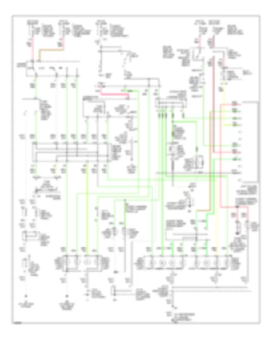
Headlights Wiring Diagram (1 of 2) for Toyota Avalon XLS 2004
 https://portal-diagnostov.com/license.html
Automotive Electricians Portal FZCO
Automotive Electricians Portal FZCO
https://portal-diagnostov.com/license.html
https://portal-diagnostov.com/license.html
Automotive Electricians Portal FZCO
Automotive Electricians Portal FZCOList of elements for Headlights Wiring Diagram (1 of 2) for Toyota Avalon XLS 2004:
- A j16
- Altl
- Auto
- Automatic light control sensor (on top left side of dash)
- Body ecu
- C13
- Cltb
- Clte
- Clts
- Combination switch
- D14
- D17
- Dcty
- Dimmer switch
- Door courtesy switch (left front) (on left "b" pillar)
- Door locks system
- Driver side j/b (behind left side of dash)
- Drl
- Drl fuse 7.5a
- E17
- Ea (at front of right front fender)
- Ed (at front of left front fender)
- Engine room j/b (on left front inner fender panel)
- Engine room r/b 5 (on left inner fender panel)
- Flash
- Foglight
- Generator generator
- Gnd2
- Head
- Head relay
- High
- Hot at all times
- Hrly
- Ig (at left end of dash)
- Interior lights system
- J/b 3 (behind left kick panel)
- J15
- J16 a
- Junction connector 15 & 16 (on top of left kick panel)
- Junction connector 4 (behind right side of dash)
- L l
- Left headlight low
- Light control switch
- Lower left head fuse 15a
- Lower right head fuse 15a
- Main fuse 40a
- Off
- Parking brake switch (on parking brake lever bracket)
- Pcty
- Pkb
- Pnk
- Prg
- Rcty
- Rda
- Red
- Right headlight low
- Switch
- Tail
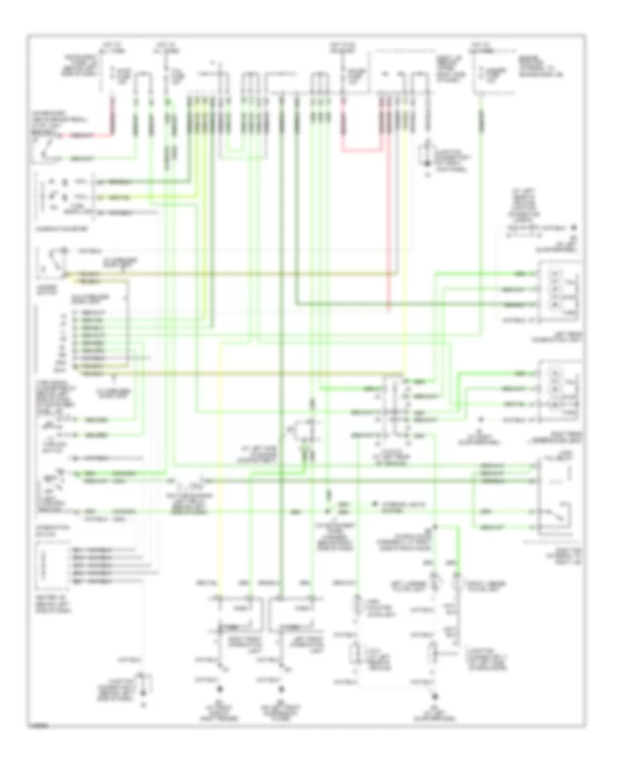
Headlights Wiring Diagram (2 of 2) for Toyota Avalon XLS 2004
 https://portal-diagnostov.com/license.html
Automotive Electricians Portal FZCO
Automotive Electricians Portal FZCO
https://portal-diagnostov.com/license.html
https://portal-diagnostov.com/license.html
Automotive Electricians Portal FZCO
Automotive Electricians Portal FZCOList of elements for Headlights Wiring Diagram (2 of 2) for Toyota Avalon XLS 2004:
- Combination meter
- Driver side j/b (behind left side of dash)
- Drl relay 2
- Drl relay 3
- Drl relay 4
- E1 (in engine compt harness, at right front of engine compt)
- Ea (at front of right front fender)
- Ecu-b fuse 7.5a
- Ed (at front of left front fender)
- Engine room j/b (on left front inner fender panel)
- Engine room r/b 2 (on right side of engine compartment)
- Fog fuse 15a
- Fog relay
- H10
- High beam ind
- Hot at all times
- Hot in on or start
- Junction connector 1 (on top of left kick panel)
- Junction connector 19 (behind right center of dash)
- Left front foglight
- Left headlight high
- Red
- Right front foglight
- Right headlight high
- Upper left head fuse 10a
- Upper right head fuse 10a
HORN
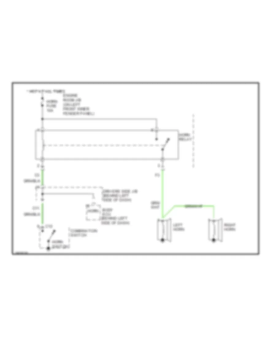
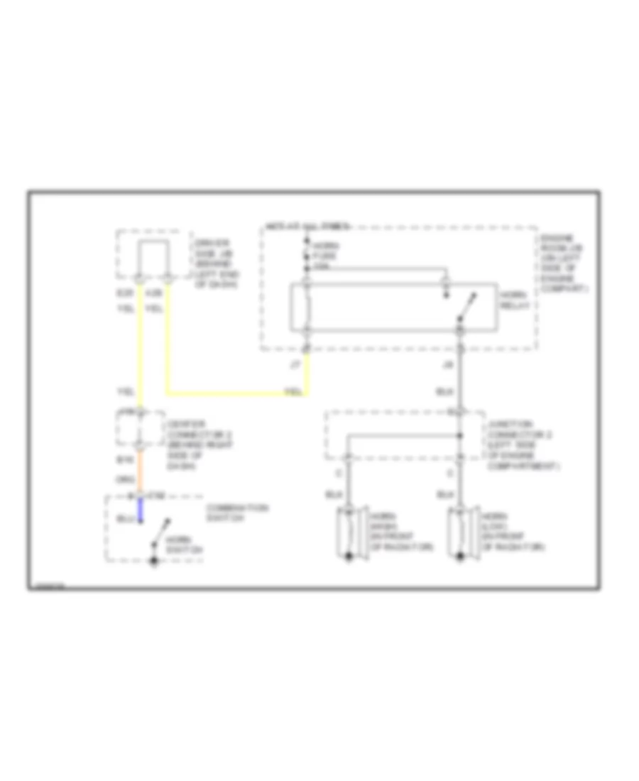
Horn Wiring Diagram for Toyota Avalon XLS 2004
 https://portal-diagnostov.com/license.html
Automotive Electricians Portal FZCO
Automotive Electricians Portal FZCO
https://portal-diagnostov.com/license.html
https://portal-diagnostov.com/license.html
Automotive Electricians Portal FZCO
Automotive Electricians Portal FZCOList of elements for Horn Wiring Diagram for Toyota Avalon XLS 2004:
- Body ecu (behind left side of dash)
- C11
- C12
- Combination switch
- Drivers side j/b (behind left side of dash)
- Engine room j/b (on left front inner fender panel)
- Horn
- Horn fuse 10a
- Horn relay
- Horn switch
- Hot at all times
- Left horn
- Right horn
INSTRUMENT CLUSTER
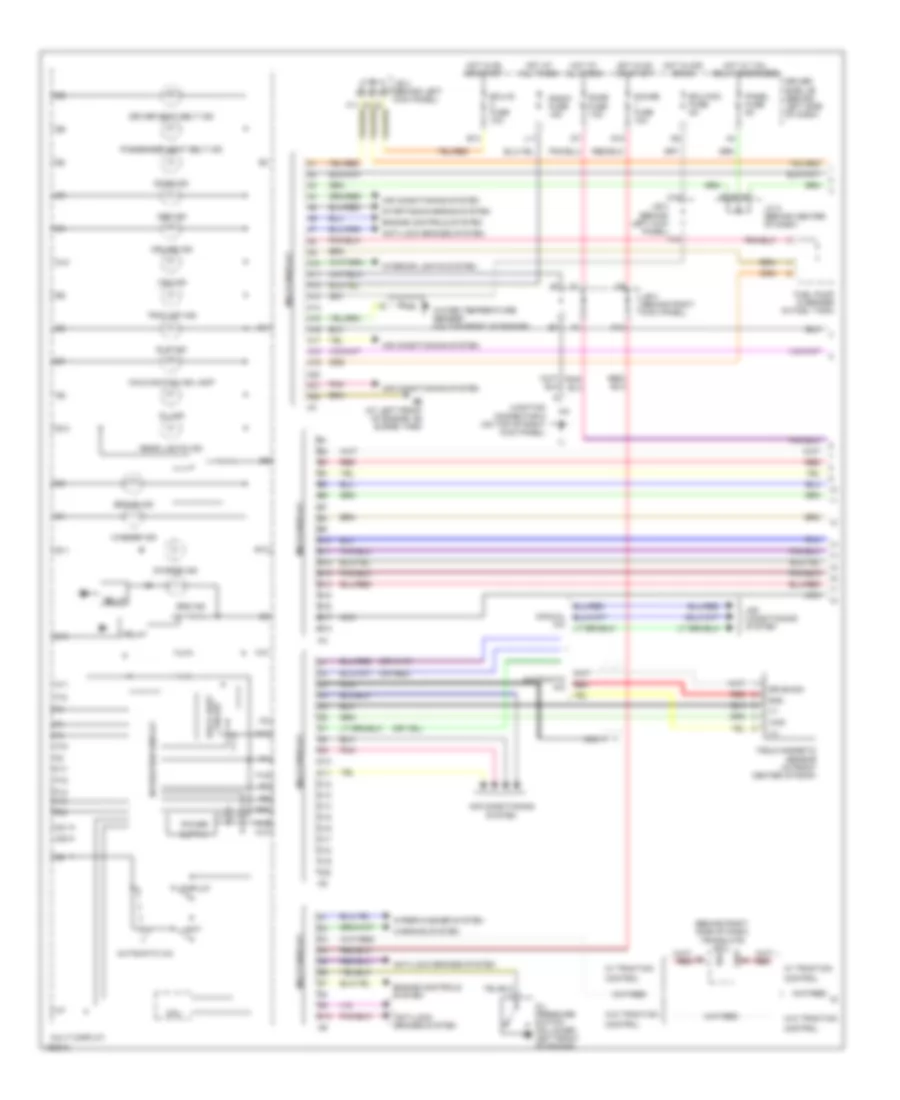
Instrument Cluster Wiring Diagram, with Navigation (1 of 2) for Toyota Avalon XLS 2004
 https://portal-diagnostov.com/license.html
Automotive Electricians Portal FZCO
Automotive Electricians Portal FZCO
https://portal-diagnostov.com/license.html
https://portal-diagnostov.com/license.html
Automotive Electricians Portal FZCO
Automotive Electricians Portal FZCOList of elements for Instrument Cluster Wiring Diagram, with Navigation (1 of 2) for Toyota Avalon XLS 2004:
- (behind right side of dash) translate ecu
- (or red)
- A10
- A11
- A12
- A12 a13
- A13
- A14
- A15
- A16
- A17
- A18
- A19
- A20
- A21
- A22
- Abs ind
- Air conditioning system
- Anti-lock brakes system
- Automatic a/c
- B10
- B11
- B12
- B13
- B14
- B15
- B16
- B17
- B18
- Back light circuit
- Brake ind
- Brl
- C10
- C11
- C12
- C13
- C14
- C15
- C16
- C17
- C18
- C19
- C20
- Charge ind
- Control
- Cpu
- Cruise ind
- D10
- Display
- Dome fuse 7.5a
- Door ind
- Drive sig
- Driver seat belt ind
- Driver side j/b (behind left side of dash)
- E10
- E11
- E12
- E13
- Eb (at left front of engine, on surge tank)
- Ecu-acc fuse 5a
- Ecu-ig fuse 10a
- Engine controls system
- F11
- F12
- F13
- F15
- F16
- F17
- F18
- F19
- F20
- F24
- Field magnetic sensor (in front center of roof)
- Fuel pump & sender (in fuel tank)
- Gauge fuse 10a
- Gnd
- Hot at all times
- Hot in acc or on
- Hot in on or start
- Hot w/ tail relay energized
- Interior lights system
- J/b 3 (behind left kick panel)
- J/b 4 (behind right kick panel)
- J/c 2 (behind center of dash)
- Junction connector 9 (on top of right kick panel)
- L11
- Light
- Lvl2
- Malfunction ind lamp
- Multi display
- Navigation display
- Nca
- Oil ind
- Oil pressure switch (on lower left front of engine)
- Panel fuse 5a
- Passenger seat belt ind
- Pnk
- Power
- Radio fuse 15a
- Rear lights ind
- Red
- Relay
- Slip ind
- Srs ind
- Starting/charging system
- Trac off ind
- Vmid
- Vsc ind
- W/ traction
- W/o traction
- Warning system
- Washer ind
- Water temperature sender (on top front of engine)
- Wiper/washer system
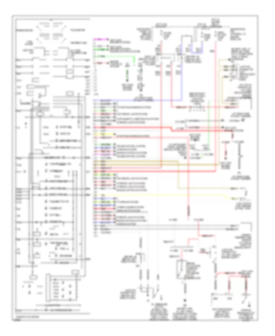
Instrument Cluster Wiring Diagram, with Navigation (2 of 2) for Toyota Avalon XLS 2004
 https://portal-diagnostov.com/license.html
Automotive Electricians Portal FZCO
Automotive Electricians Portal FZCO
https://portal-diagnostov.com/license.html
https://portal-diagnostov.com/license.html
Automotive Electricians Portal FZCO
Automotive Electricians Portal FZCOList of elements for Instrument Cluster Wiring Diagram, with Navigation (2 of 2) for Toyota Avalon XLS 2004:
- (at front side of right fender)
- (behind right side of dash) junction connector 3 & 4
- (except xrs:
- (except xrs: at rear left side of cylinder head) (xrs: at rear of engine) ec
- (in instrument panel harness, behind upper left side of dash)
- (on top of transaxle)
- (w/o abs) vehicle speed sensor (combination meter)
- (xrs: on left front suspension tower)
- A10
- A11
- A12
- A14
- A15
- A16
- A17
- A18
- A19
- A20
- A21
- A22
- A23
- A24
- A25
- A26
- A27
- A29
- A30
- A31
- A32
- A33
- A34
- A35
- A36
- A37
- A38
- A39
- A40
- Abs ind
- Ambient temperature sensor (at middle front of engine compt)
- Anti-lock brakes systeam
- Anti-lock brakes systeam engine controls system
- Anti-lock brakes system
- At left front suspension tower)
- B16
- B18
- B20
- B21
- B22
- Brake fluid level warning switch (on brake fluid reservoir)
- Brake ind
- Brk
- Buzzer
- C11
- C18
- C19
- C20
- Center j/b (behind left side of dash)
- Charge ind
- Combination meter
- Cruise control system
- Cruise ind
- Daytime running light relay (behind left side of dash)
- Dome fuse 15a
- Door ind
- Engine controls system
- Engine room r/b (integral to engine room j/b)
- Exterior lights system
- Fuel gauge
- Fuel ind
- Fuel pump & fuel sender (in fuel tank)
- Gauge fuse 10a
- Head ind
- Head rh upr fuse 10a
- Headlights system
- High beam ind
- Hot at all times
- Hot in on or start
- Hot w/ dimmer relay energized
- Illumination
- Ind
- Instrument panel j/b (behind left side of dash)
- Interior lights system
- Junction connector 1 (at left side of engine compt)
- Junction connector 2 (behind left side of dash)
- Junction connector 5 & 6 (behind right side of dash)
- Left turn ind
- Maint reqd ind
- Malfunction ind
- O/d off ind
- Odo/trip lcd
- Oil pressure ind
- Oil pressure switch (except xrs: on lower left side of engine) (xrs: at right rear of engine)
- Out side temperature lcd
- Parking brake switch (at base of park brake lever)
- Pkb
- Red
- Right j/b (behind upper right side of dash)
- Right turn ind
- Seat belt ind
- Slip ind
- Speedometer
- Srs ind
- Starting/charging system
- Tachometer
- Temperature
- Tire pressure
- Vsc
- W/ abs
- W/o abs
- Warning system
- Washer level ind
- Wiper/washer system
Instrument Cluster Wiring Diagram, without Navigation (1 of 2) for Toyota Avalon XLS 2004
 https://portal-diagnostov.com/license.html
Automotive Electricians Portal FZCO
Automotive Electricians Portal FZCO
https://portal-diagnostov.com/license.html
https://portal-diagnostov.com/license.html
Automotive Electricians Portal FZCO
Automotive Electricians Portal FZCOList of elements for Instrument Cluster Wiring Diagram, without Navigation (1 of 2) for Toyota Avalon XLS 2004:
- (behind right side of dash) translate ecu
- (or red)
- A10
- A11
- A12
- A12 a13
- A13
- A14
- A15
- A16
- A17
- A18
- A19
- A20
- A21
- A22
- Abs ind
- Air conditioning system
- Anti-lock brakes system
- Automatic a/c
- B10
- B11
- B12
- B13
- B14
- B15
- B16
- B17
- B18
- Back light circuit
- Brake ind
- Brl
- C10
- C11
- C12
- C13
- C14
- C15
- C16
- C17
- C18
- C19
- C20
- Charge ind
- Control
- Cpu
- Cruise ind
- D10
- Display
- Dome fuse 7.5a
- Door ind
- Drive sig
- Driver seat belt ind
- Driver side j/b (behind left side of dash)
- E10
- E11
- E12
- E13
- E14
- E15
- Eb (at left front of engine, on surge tank)
- Ecu-acc fuse 5a
- Ecu-ig fuse 10a
- Engine controls system
- F11
- F13
- F15
- Field magnetic sensor (automatic a/c) (in front center of roof)
- Fuel pump & sender (in fuel tank)
- G20
- Gauge fuse 10a
- Gnd
- Hot at all times
- Hot in acc or on
- Hot in on or start
- Hot w/ tail relay energized
- Interior lights system
- J/b 3 (behind left kick panel)
- J/b 4 (behind right kick panel)
- J/c 2 (behind center of dash)
- Junction connector 9 (on top of right kick panel)
- L11
- Light
- Lvl2
- Malfunction ind lamp
- Mode
- Multi display
- Nca
- Odo/trip
- Oil ind
- Oil pressure switch (on lower left front of engine)
- Panel fuse 5a
- Passenger seat belt ind
- Pnk
- Power
- Radio fuse 15a
- Rear lights ind
- Red
- Relay
- Reset/adj
- Slip ind
- Srs ind
- Starting/charging system
- Trac off ind
- Vmid
- Vsc ind
- W/ traction
- W/o traction
- Warning system
- Washer ind
- Water temperature sender (on top front of engine)
- Wiper/washer system
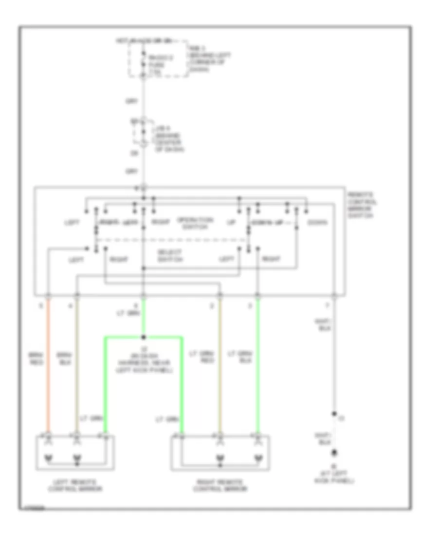
Instrument Cluster Wiring Diagram, without Navigation (2 of 2) for Toyota Avalon XLS 2004
 https://portal-diagnostov.com/license.html
Automotive Electricians Portal FZCO
Automotive Electricians Portal FZCO
https://portal-diagnostov.com/license.html
https://portal-diagnostov.com/license.html
Automotive Electricians Portal FZCO
Automotive Electricians Portal FZCOList of elements for Instrument Cluster Wiring Diagram, without Navigation (2 of 2) for Toyota Avalon XLS 2004:
- Down
- Hot in acc or on
- I2 (in dash harness, near left kick panel)
- Ie (at left kick panel)
- J/b 6 (behind center of dash)
- Left
- Left remote control mirror
- Operation switch
- R/b 3 (behind left corner of dash)
- Radio 2 fuse 7.5a
- Remote control mirror switch
- Right
- Right remote control mirror
- Select switch
MEMORY SYSTEMS
Memory Mirrors Wiring Diagram for Toyota Avalon XLS 2004
 https://portal-diagnostov.com/license.html
Automotive Electricians Portal FZCO
Automotive Electricians Portal FZCO
https://portal-diagnostov.com/license.html
https://portal-diagnostov.com/license.html
Automotive Electricians Portal FZCO
Automotive Electricians Portal FZCOList of elements for Memory Mirrors Wiring Diagram for Toyota Avalon XLS 2004:
- A28
- B16
- C12
- Center connector 2 (behind right side of dash)
- Combination switch
- Driver side j/b (behind left end of dash)
- E25
- Engine room j/b (on left side of engine compart)
- Horn (high) (in front of radiator)
- Horn (low) (in front of radiator)
- Horn fuse 10a
- Horn relay
- Horn switch
- Hot at all times
- I16
- Junction connector 2 (left side of engine compartment)
Memory Seat Wiring Diagram for Toyota Avalon XLS 2004
 https://portal-diagnostov.com/license.html
Automotive Electricians Portal FZCO
Automotive Electricians Portal FZCO
https://portal-diagnostov.com/license.html
https://portal-diagnostov.com/license.html
Automotive Electricians Portal FZCO
Automotive Electricians Portal FZCOList of elements for Memory Seat Wiring Diagram for Toyota Avalon XLS 2004:
- (behind left side of dash) body ecu
- (below driver's seat)
- (below driver's seat) power seat motor (driver's seat front vertical control)
- (below driver's seat) power seat motor (driver's seat rear vertical control)
- (below driver's seat) power seat motor (driver's seat reclining control)
- (below driver's seat) power seat motor (driver's seat slide control)
- (below front passenger's seat) power seat motor (front passengr's seat rear vertical control)
- (below front passenger's seat) power seat motor (front passengr's seat reclining control)
- (below front passenger's seat) power seat motor (front passengr's seat slide control)
- (in body harness, under left front seat) b12
- At left kick panel)
- B12
- B12 (under left front seat)
- B14
- Driver side j/b (behind left side of dash)
- Driver's power seat control switch
- Driver's seat lumbar support control switch (w/ floor shift)
- E14
- Ecu-b fuse 7.5a
- Fdwn
- Front passenger's power seat control switch
- Frv+
- Frv-
- Fup
- Gauge 1 fuse 10a
- Gnd
- Hot at all times
- Hot in on or start
- Ih (at right center of dash)
- J/b 3 (behind left kick panel)
- J/c 10 (in right front side of luggage compt)
- J/c 11 (in left front side of luggage compt)
- J/c 14 (under left front seat)
- J/c 3 (behind right center of dash)
- Ldwn
- Lft+
- Lft-
- Lumbar support control switch (driver's seat)
- Lup
- Memory mirrors circuit
- Mirb
- Mire
- Mirg
- Mmry
- Mpx1
- Mpx2
- P20
- P21
- Pnk
- Power seat ecu (under driver's seat)
- Power seat position sensor (driver's seat front vertical control
- Power seat position sensor (driver's seat rear vertical control)
- Power seat position sensor (driver's seat reclining control)
- Power seat position sensor (driver's seat slide control) (below driver's seat)
- Pvcc
- Pwr seat fuse 30a
- Rcl+
- Rcl-
- Rclf
- Rclr
- Rdwn
- Red
- Rup
- Seat memory switch
- Set
- Sgnd
- Sld+
- Sld-
- Sldf
- Sldr
- Ssfv
- Ssrl
- Ssrr
- Ssrs
- Sw1
- Sw2
- Swe
- Sysb
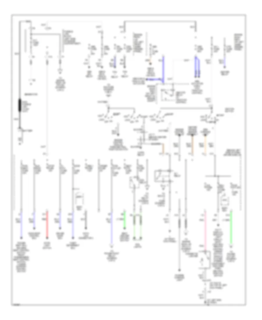
POWER DISTRIBUTION
Power Distribution Wiring Diagram (1 of 3) for Toyota Avalon XLS 2004
 https://portal-diagnostov.com/license.html
Automotive Electricians Portal FZCO
Automotive Electricians Portal FZCO
https://portal-diagnostov.com/license.html
https://portal-diagnostov.com/license.html
Automotive Electricians Portal FZCO
Automotive Electricians Portal FZCOList of elements for Power Distribution Wiring Diagram (1 of 3) for Toyota Avalon XLS 2004:
- (at left end of dash) ig
- (behind left side of dash) driver side j/b
- A13
- Abs & ba & trac & vsc actuator
- Abs & ba & trac & vsc ecu
- Abs actuator & ecu (w/o traction control)
- Abs fuse 25a
- Abs fuse 5a
- Abs fuse 60a
- Abs mtr relay (w/ traction control)
- Abs sol relay
- Acc
- Alt fuse 120a
- Am 1 fuse 40a
- B10
- B12
- Battery
- Bdr1
- Body ecu
- C/opn relay
- C10
- Cds fuse 30a
- Center air bag sensor assembly
- Charge warning light
- Cig fuse 15a
- Cigarette lighter
- D11
- D12
- Data link connector 3
- Door fuse 25a
- Driver door ecu
- Ecu- acc fuse 5a
- Engine control module
- Engine control module, park/neutral position switch
- Engine room j/b (on left front inner fender panel)
- Engine room r/b 3 (on left front of engine compt)
- Engine room r/b 5 (on left inner fender panel)
- F10
- Fan relay
- Fl p/w fuse 25a
- Fog fuse 15a
- Fog lights
- Fog relay
- Fusible link block (left side of engine compartment)
- Generator
- Heater relay
- Htr fuse 50a
- I13
- Ig 1 relay
- Ignition switch
- Ii (at right kick panel)
- J/c 15 & 16 (on top of left kick panel)
- J/c 17 (behind center of dash)
- J15
- J16
- Lock
- Moon roof control ecu
- Multi display, back-up light circuit, shift lock ecu, remote control mirror switch, radio & player, stereo component amplifier, park/ neutral position switch
- Nca
- Obd ii fuse 7.5a
- Off
- Opner fuse 5a
- Pnk
- Power seat ecu, driver's seat control switch, front passenger's seat control switch, lumbar support control switch
- Pwr outlet fuse 15a
- Pwr seat fuse 30a
- Rdi fuse 30a
- Red
- Seat heater control switch
- Seat htr fuse 20a
- Srs warning light
- Start
- Stop fuse 15a
- Stop- light switch
- Sun roof fuse 30a
- Theft deterrent ecu
- To am2 fuse (diagram 2 of 3)
- To ecu-ig fuse (diagram 2 of 3)
- To engine room j/b (pin c11) (diagram 2 of 3)
- To engine room j/b (pin g2) (diagram 2 of 3)
- To power outlet (diagram 3 of 3)
- To power point relay (diagram 3 of 3)
- To tail relay (diagram 2 of 3)
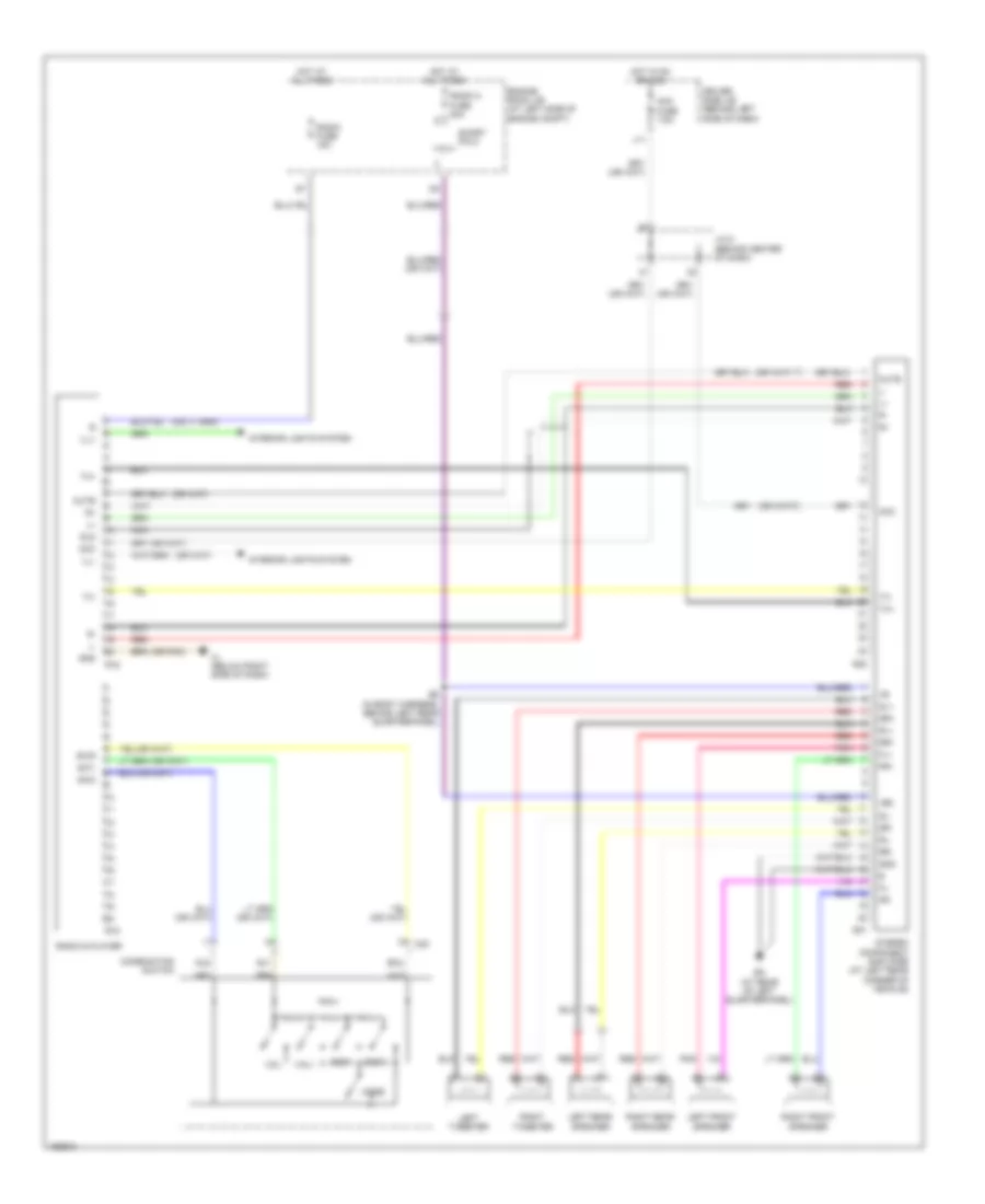
Power Distribution Wiring Diagram (2 of 3) for Toyota Avalon XLS 2004
 https://portal-diagnostov.com/license.html
Automotive Electricians Portal FZCO
Automotive Electricians Portal FZCO
https://portal-diagnostov.com/license.html
https://portal-diagnostov.com/license.html
Automotive Electricians Portal FZCO
Automotive Electricians Portal FZCOList of elements for Power Distribution Wiring Diagram (2 of 3) for Toyota Avalon XLS 2004:
- (or pnk)
- +b2
- Acc
- Acc fuse 7.5a
- Au1
- Au2
- B5 (in body harness, behind left rear quarterpanel)
- Bk (at rear of left quarterpanel)
- C20
- Combination switch
- Driver side j/b (behind left side of dash)
- Eau
- Engine room j/b (at left side of engine compt)
- Fl+
- Fl-
- Fr+
- Fr-
- Gnd
- Hot at all times
- Hot in on or acc
- Ih (below right side of dash)
- Ill+
- Ill-
- Interior lights system
- J/c 5 (behind center of dash)
- J11
- Left front speaker
- Left rear speaker
- Left tweeter
- Mode
- Mute
- Nca
- Pnk
- R15
- R16
- Radio & player
- Radio 2 fuse 30a
- Radio fuse 15a
- Red
- Right front speaker
- Right rear speaker
- Right tweeter
- Rl+
- Rl-
- Rr+
- Rr-
- S21
- S22
- Seek+
- Seek-
- Short pin 2
- Sl+
- Sl-
- Sld
- Sr+
- Sr-
- Stereo component amplifier (at left rear corner of vehicle)
- Sw1
- Sw2
- Swg
- Tx+
- Tx-
- Vol+
- Vol-
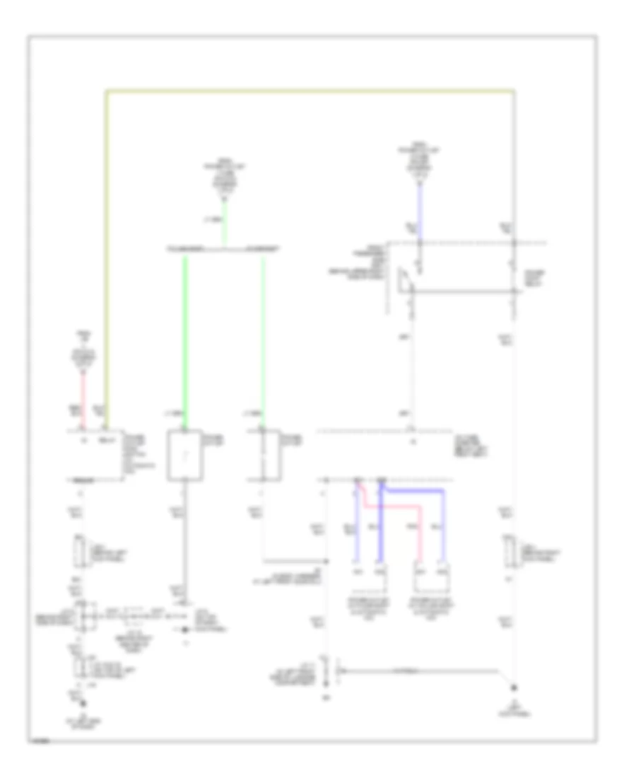
Power Distribution Wiring Diagram (3 of 3) for Toyota Avalon XLS 2004
 https://portal-diagnostov.com/license.html
Automotive Electricians Portal FZCO
Automotive Electricians Portal FZCO
https://portal-diagnostov.com/license.html
https://portal-diagnostov.com/license.html
Automotive Electricians Portal FZCO
Automotive Electricians Portal FZCOList of elements for Power Distribution Wiring Diagram (3 of 3) for Toyota Avalon XLS 2004:
- (pin d13) (diagram 2 of 3)
- 1 fuse (pin d12) (diagram 1 of 3)
- 2 fuse (pin b7) (diagram 1 of 3)
- Ac1
- Ac2
- B1 (in body harness, at left front door sill)
- B21
- C20
- Column shift
- Floor shift
- From j/b
- From power outlet
- Front passenger side r/b 7 (behind upper right side of dash)
- Ground
- If (left kick panel)
- Ig (at left end of dash)
- J/b 3 (behind left kick panel)
- J/b 4 (behind right kick panel)
- J/c 11 (in left front side of luggage compartment)
- J/c 15 & 16 (on top of left kick panel)
- J/c 18 (behind right center of dash)
- J/c 5 (behind right side of dash)
- J/c 9 (on top of right kick panel)
- J15
- J16
- Pnk
- Power outlet
- Power outlet (w/ column shift & automatic a/c)
- Power outlet (w/ floor shift & automatic a/c)
- Power outlet main switch (w/ automatic a/c)
- Power point relay
- Relay
- Voltage inverter (below left front seat)
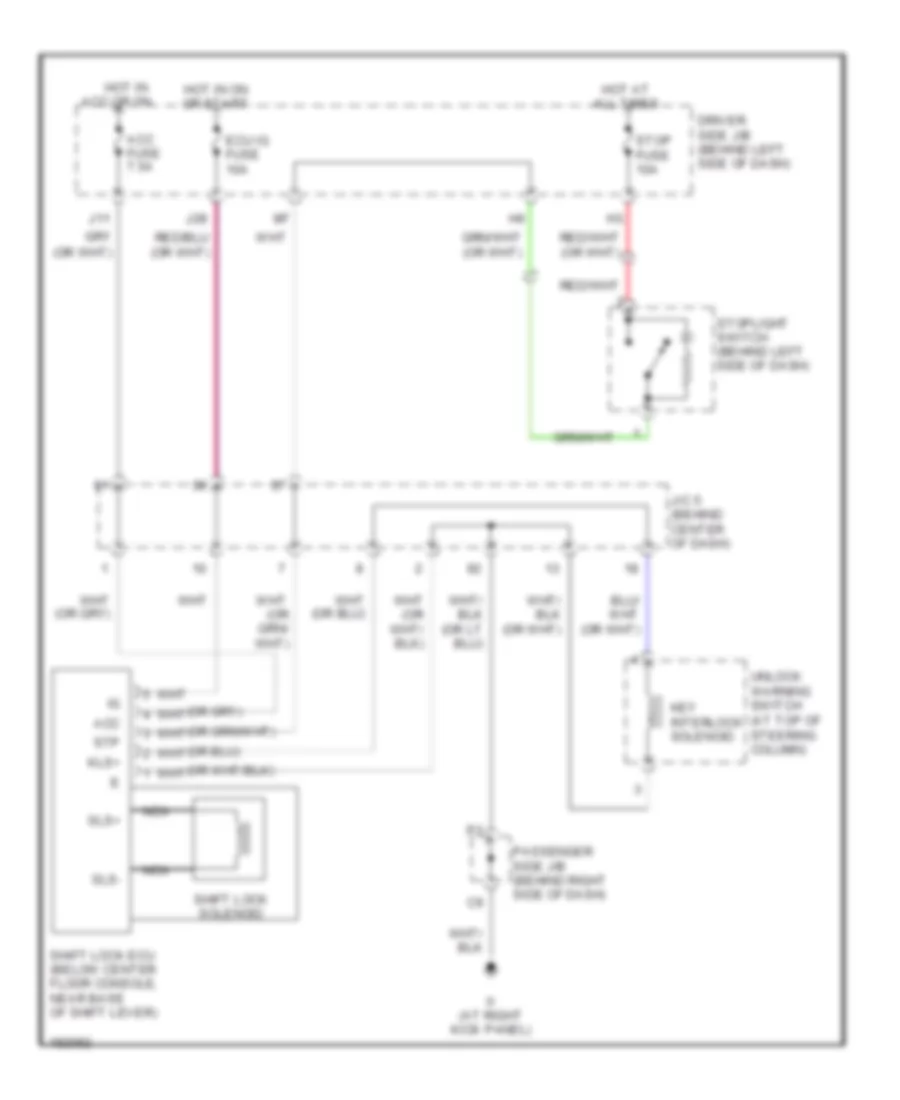
POWER DOOR LOCKS
Power Door Locks Wiring Diagram, with Keyless Entry for Toyota Avalon XLS 2004
 https://portal-diagnostov.com/license.html
Automotive Electricians Portal FZCO
Automotive Electricians Portal FZCO
https://portal-diagnostov.com/license.html
https://portal-diagnostov.com/license.html
Automotive Electricians Portal FZCO
Automotive Electricians Portal FZCOList of elements for Power Door Locks Wiring Diagram, with Keyless Entry for Toyota Avalon XLS 2004:
- Acc
- Acc fuse 7.5a
- Driver side j/b (behind left side of dash)
- Ecu ig fuse 10a
- Hot at all times
- Hot in acc or on
- Hot in on or start
- Ii (at right kick panel)
- J/c 5 (behind center of dash)
- J11
- J28
- Key interlock solenoid
- Kls+
- Nca
- Passenger side j/b (behind right side of dash)
- Shift lock ecu (below center floor console, near base of shift lever)
- Shift lock solenoid
- Sls+
- Sls-
- Stop fuse 10a
- Stoplight switch (behind left side of dash)
- Stp
- Unlock warning switch (at top of steering column)
Power Door Locks Wiring Diagram, without Keyless Entry for Toyota Avalon XLS 2004
 https://portal-diagnostov.com/license.html
Automotive Electricians Portal FZCO
Automotive Electricians Portal FZCO
https://portal-diagnostov.com/license.html
https://portal-diagnostov.com/license.html
Automotive Electricians Portal FZCO
Automotive Electricians Portal FZCOList of elements for Power Door Locks Wiring Diagram, without Keyless Entry for Toyota Avalon XLS 2004:
- (at center rear of luggage compt) bm
- (at left end of dash) ig
- (at right kick panel) ii
- (behind center of dash) j/c 2
- (behind right center of dash) j/c 3
- A11
- Act+
- Act-
- Actd
- Bdr1
- Bdr2
- Body ecu
- C12
- Cpub
- D14
- D17
- D22
- Dcty
- Door 1 fuse 25a
- Door 2 fuse 15a
- Driver door ecu (in driver's door)
- Driver side j/b (behind left side of dash)
- E17
- Ecu-b fuse 7.5a
- Ecu-ig 2 fuse 10a
- Engine room j/b (on left front inner fender panel)
- F14
- F17
- F19
- Front passenger door ecu (in right front door)
- Gnd
- Gnd1
- Gnd2
- Hot at all times
- Hot in on or start
- I21
- If (at left kick panel)
- Ig (at left end of dash)
- Ii (at right kick panel)
- J/b 3 (behind left kick panel)
- J/b 4 (behind right kick panel)
- J/c 11 (in left front side of luggage compt)
- J/c 4 (behind right side of dash)
- J/c 9 (on top of right kick panel)
- Keye
- Ksw
- Kul
- Left front door courtesy switch (on left "b" pillar)
- Left front door lock motor, door unlock detection switch & door key lock & unlock switch (in left front door)
- Left rear door lock motor (in left rear door)
- Lock
- Lsr
- Lswd
- Lswp
- Luggage compartment door opener main switch
- Luggage compartment door opener motor
- Luggage compartment door opener switch
- Mpx1
- Mpx2
- Mpx4
- Pcty
- Right front door courtesy switch (on right "b" pillar)
- Right front door lock motor, door unlock detection switch & door key lock & unlock switch (in right front door)
- Right rear door lock motor (in right rear door)
- Sig
- Tku
- Tr+
- Unlk
- Unlock warning switch (behind left side of dash)
POWER MIRRORS
Electrochromic Mirror Wiring Diagram for Toyota Avalon XLS 2004
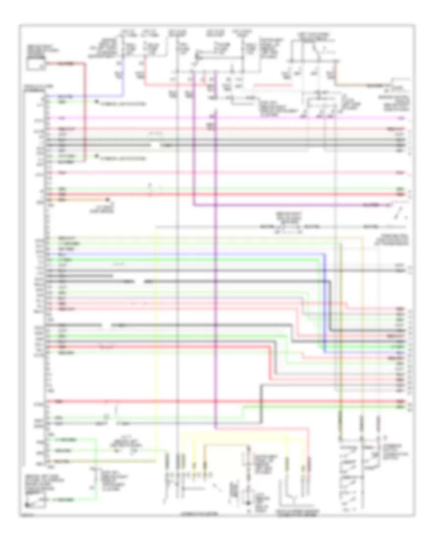 https://portal-diagnostov.com/license.html
Automotive Electricians Portal FZCO
Automotive Electricians Portal FZCO
https://portal-diagnostov.com/license.html
https://portal-diagnostov.com/license.html
Automotive Electricians Portal FZCO
Automotive Electricians Portal FZCOList of elements for Electrochromic Mirror Wiring Diagram for Toyota Avalon XLS 2004:
- (behind left side of dash, on parking brake lever) parking brake switch
- (behind right center of dash) antenna amplifier
- (behind right end of dash) j/c 51 & 52
- (left kick panel) acc cut relay
- A12
- A15
- Acc
- Accr
- Ant
- Atx+
- Atx-
- Au1
- Au2
- C9 steering switch (combination switch)
- Cdl+
- Cdl-
- Cdr+
- Cdr-
- Combination meter
- Csld
- Eau
- Ecu-b fuse 7.5a
- Engine control module (behind right side of dash)
- Engine room j/b (on left side of engine compartment)
- F12
- Gauge fuse 15a
- Gnd
- H11
- Hot at all times
- Hot in acc or on
- Hot in on or start
- Ign1 fuse 10a
- Ill+
- Ill-
- Instrument panel j/b (behind left end of dash)
- Interior lights system
- Io (at right dash brace)
- Ipo
- Ivo+
- Ivo-
- J/c 17 (behind left center of dash)
- J/c 37 & 38 (left side of dash) j38
- J/c 8 (behind left end of dash)
- J37
- J51
- J52
- Mode
- Mute
- Nca
- Ntsc
- Park/neutral position switch (on transmission)
- Pkb
- Pnk
- R-l+
- R-l-
- R-r+
- R-r-
- R26
- R27
- R28
- R29
- R30
- Rad 1 fuse 20a
- Rad 2 fuse 7.5a
- Radio & player w/ display
- Red
- Rev
- Rmut
- Rsld
- Seek+
- Seek-
- Sgd1
- Sgnd
- Sld
- Sld1
- Spd
- Speedo- meter
- Sub j/b 3 (behind right side of instrument cluster)
- Sub j/b 4 (behind right side of instrument cluster)
- Sw1
- Sw2
- Swg
- Tx+
- Tx-
- Vehicle speed sensor (combination meter)
- Vol+
- Vol-
Power Mirrors Wiring Diagram for Toyota Avalon XLS 2004
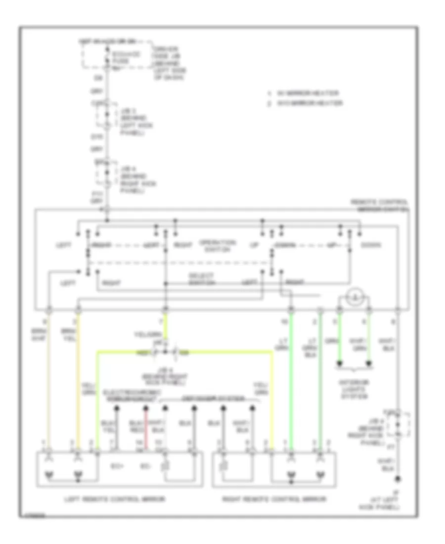 https://portal-diagnostov.com/license.html
Automotive Electricians Portal FZCO
Automotive Electricians Portal FZCO
https://portal-diagnostov.com/license.html
https://portal-diagnostov.com/license.html
Automotive Electricians Portal FZCO
Automotive Electricians Portal FZCOList of elements for Power Mirrors Wiring Diagram for Toyota Avalon XLS 2004:
- C15
- D15
- Defogger system
- Down
- Driver side j/b (behind left side of dash)
- Ec+
- Ec-
- Ecu-acc fuse 5a
- Electrochromic mirror circuit
- F20
- H22
- Hot in acc or on
- If (at left kick panel)
- Interior lights system
- J/b 3 (behind left kick panel)
- J/b 4 (behind right kick panel)
- J/b 4 (behind right kick panel)
- Left
- Left remote control mirror
- Operation switch
- Remote control mirror switch
- Right
- Right remote control mirror
- Select switch
- W/ mirror heater
- W/o mirror heater
POWER SEATS
Heated Seats Wiring Diagram for Toyota Avalon XLS 2004
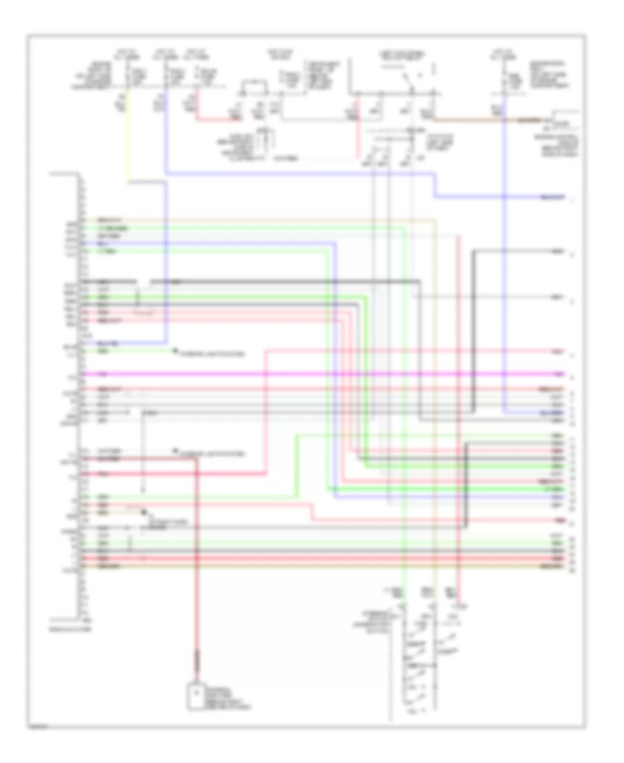 https://portal-diagnostov.com/license.html
Automotive Electricians Portal FZCO
Automotive Electricians Portal FZCO
https://portal-diagnostov.com/license.html
https://portal-diagnostov.com/license.html
Automotive Electricians Portal FZCO
Automotive Electricians Portal FZCOList of elements for Heated Seats Wiring Diagram for Toyota Avalon XLS 2004:
- (left kick panel) acc cut relay
- A12
- Acc+b
- Accr
- Ant+b
- Antenna amplifier (behind right center of dash)
- Au1
- Au2
- Bu+b
- Eau
- Ecu-b fuse 7.5a
- Engine control module (behind right side of dash)
- Engine room j/b (on left side of engine compartment)
- Engine room r/b 2 (on left side of engine compartment)
- F12
- Gnd
- Hot at all times
- Hot in on or acc
- Ill+
- Ill-
- Instrument panel j/b (behind left end of dash)
- Interior lights system
- Io (at right dash brace)
- J/c 37 & 38 (left side of dash)
- J37
- J38
- Mode
- Mute
- Nca
- Pnk
- R19
- R20
- Rad 1 fuse 20a
- Rad 2 fuse 7.5a
- Rad 3 fuse 30a
- Radio & player
- Red
- Rmu
- Rse fuse 7.5a
- Rsl+
- Rsl-
- Rsr+
- Rsr-
- S-gnd
- Seek+
- Seek-
- Sld1
- Steering switch (combination switch)
- Sub j/b 3 (behind right side of instrument cluster)
- Sw1
- Sw2
- Tx+
- Tx-
- Tx1+
- Tx1-
- Vol-
Power & Lumbar Seat Wiring Diagram for Toyota Avalon XLS 2004
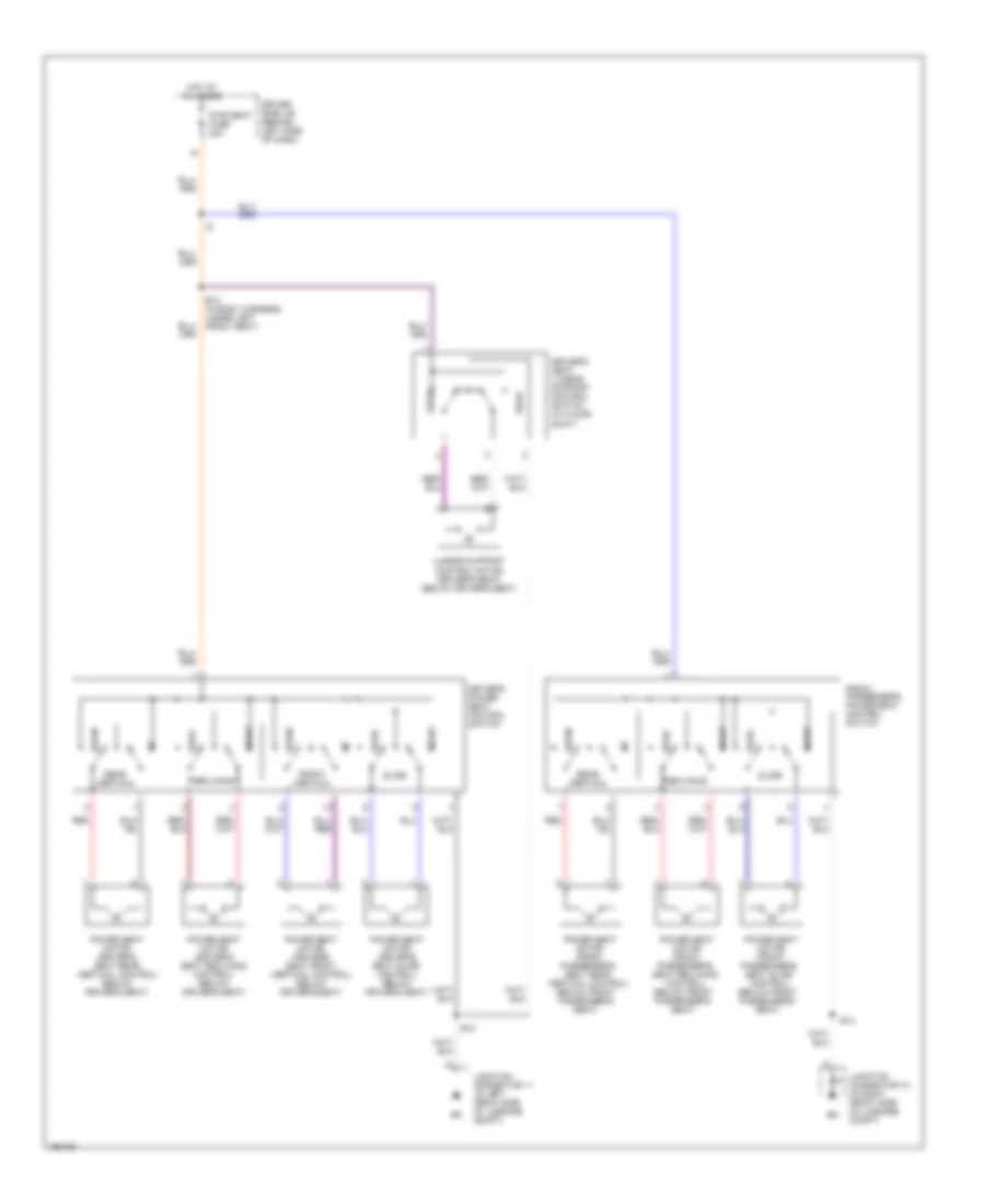 https://portal-diagnostov.com/license.html
Automotive Electricians Portal FZCO
Automotive Electricians Portal FZCO
https://portal-diagnostov.com/license.html
https://portal-diagnostov.com/license.html
Automotive Electricians Portal FZCO
Automotive Electricians Portal FZCOList of elements for Power & Lumbar Seat Wiring Diagram for Toyota Avalon XLS 2004:
- B12
- B12 (in body harness, under left front seat)
- B14
- Down
- Driver side j/b (behind left side of dash)
- Driver's power seat control switch
- Driver's seat lumbar support control switch (w/ floor shift)
- Front
- Front passenger's power seat control switch
- Front vertical
- Hot at all times
- Junction connector 10 (in right front side of luggage compt)
- Junction connector 11 (in left front side of luggage compt)
- Lumbar support control motor (driver's seat) (below driver's seat)
- Power seat motor (driver's seat front vertical control) (below driver's seat)
- Power seat motor (driver's seat rear vertical control) (below driver's seat)
- Power seat motor (driver's seat reclining control) (below driver's seat)
- Power seat motor (driver's seat slide control) (below driver's seat)
- Power seat motor (front passenger's seat rear vertical control) (below front passenger's seat)
- Power seat motor (front passenger's seat reclining control) (below front passenger's seat)
- Power seat motor (front passenger's seat slide control) (below front passenger's seat)
- Pwr seat fuse 30a
- Rear
- Rear vertical
- Reclining
- Red
- Slide
POWER WINDOWS
Power Windows Wiring Diagram for Toyota Avalon XLS 2004
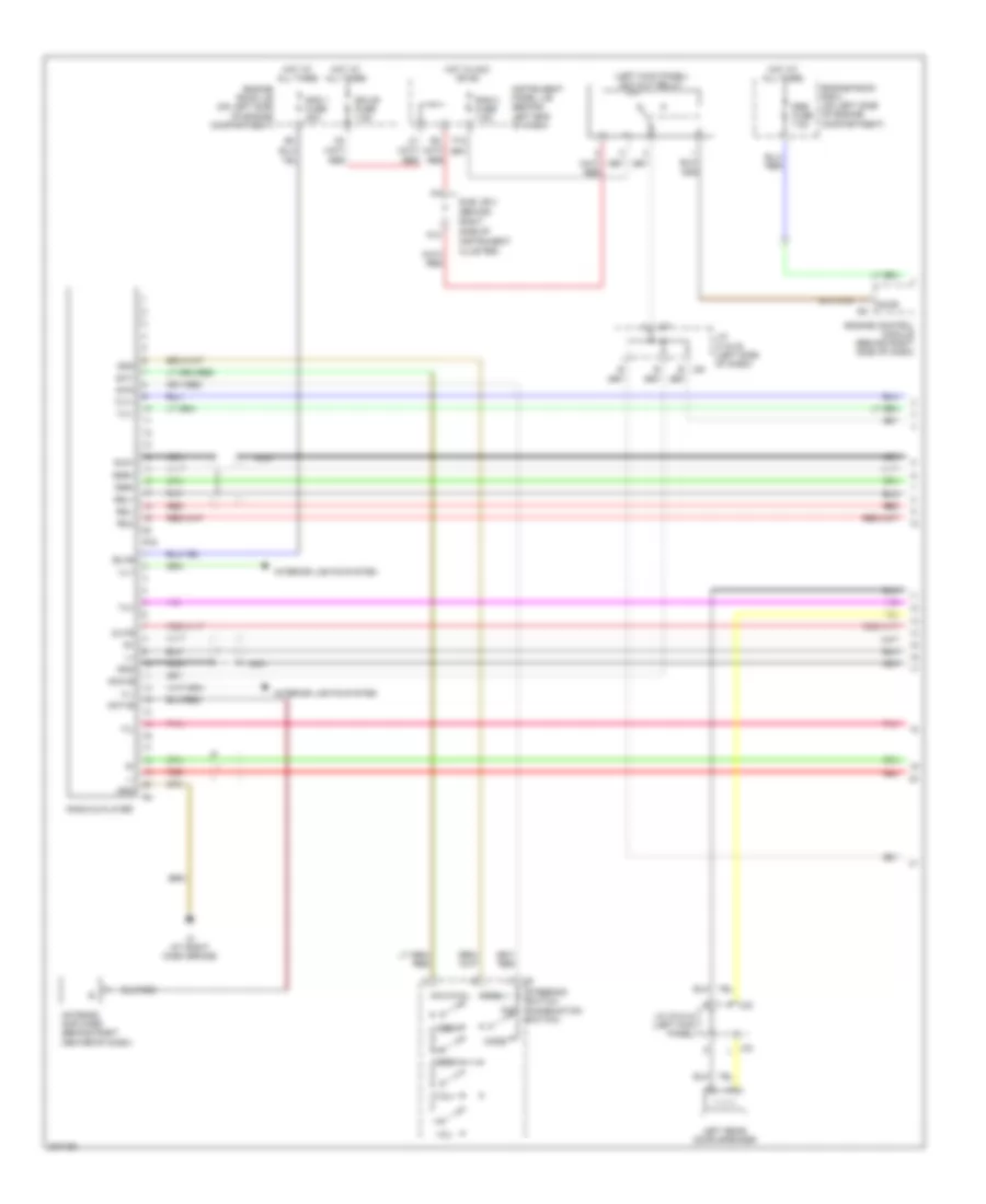 https://portal-diagnostov.com/license.html
Automotive Electricians Portal FZCO
Automotive Electricians Portal FZCO
https://portal-diagnostov.com/license.html
https://portal-diagnostov.com/license.html
Automotive Electricians Portal FZCO
Automotive Electricians Portal FZCOList of elements for Power Windows Wiring Diagram for Toyota Avalon XLS 2004:
- (behind
- (left kick panel) acc cut relay
- A12
- Acc+b
- Accr
- Ant+b
- Antenna amplifier (behind right center of dash)
- Au1
- Au2
- Bu+b
- Cluster)
- Eau
- Ecu-b fuse 7.5a
- Engine control module (behind right side of dash)
- Engine room j/b (on left side of engine compartment)
- Engine room r/b 2 (on left side of engine compartment)
- F j33
- F12
- Gnd
- Hot at all times
- Hot in acc or on
- Ill+
- Ill-
- Instrument
- Instrument panel j/b (behind left end of dash)
- Interior lights system
- Io (at right dash brace)
- J/c 33 & 34 (left kick panel)
- J/c 37 & 38 (left side of dash)
- J34 l
- J37
- J38
- Left rear door speaker
- Mode
- Mute
- Nca
- Pnk
- R19
- Rad 1 fuse 20a
- Rad 2 fuse 7.5a
- Radio & player
- Red
- Right
- Rmu
- Rse fuse 7.5a
- Rsl+
- Rsl-
- Rsr+
- Rsr-
- Seek+
- Seek-
- Side of
- Sld1
- Steering switch (combination switch)
- Sub j/b 3
- Sw1
- Sw2
- Tx+
- Tx-
- Tx1+
- Tx1-
- Vol+
- Vol-
RADIO
6-Speaker System Wiring Diagram for Toyota Avalon XLS 2004
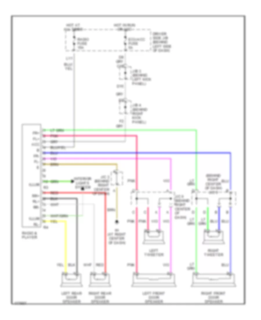 https://portal-diagnostov.com/license.html
Automotive Electricians Portal FZCO
Automotive Electricians Portal FZCO
https://portal-diagnostov.com/license.html
https://portal-diagnostov.com/license.html
Automotive Electricians Portal FZCO
Automotive Electricians Portal FZCOList of elements for 6-Speaker System Wiring Diagram for Toyota Avalon XLS 2004:
- (behind right center of dash) j/c 3
- Acc
- C15
- D15
- Driver side j/b (behind left side of dash)
- Ecu-acc fuse 5a
- Fl+
- Fl-
- Fr+
- Fr-
- Hot at all times
- Hot in run or acc
- Ih (at right center of dash)
- Illum
- Interior lights system
- J/b 3 (behind left kick panel)
- J/b 4 (behind right kick panel)
- J/c 3 (behind right center of dash)
- J/c 6 (behind right center of dash)
- L11
- Left front door speaker
- Left rear door speaker
- Left tweeter
- Pnk
- Radio & player
- Radio fuse 15a
- Red
- Right front door speaker
- Right rear door speaker
- Right tweeter
- Rl+
- Rl-
- Rr+
- Rr-
7-Speaker System Wiring Diagram for Toyota Avalon XLS 2004
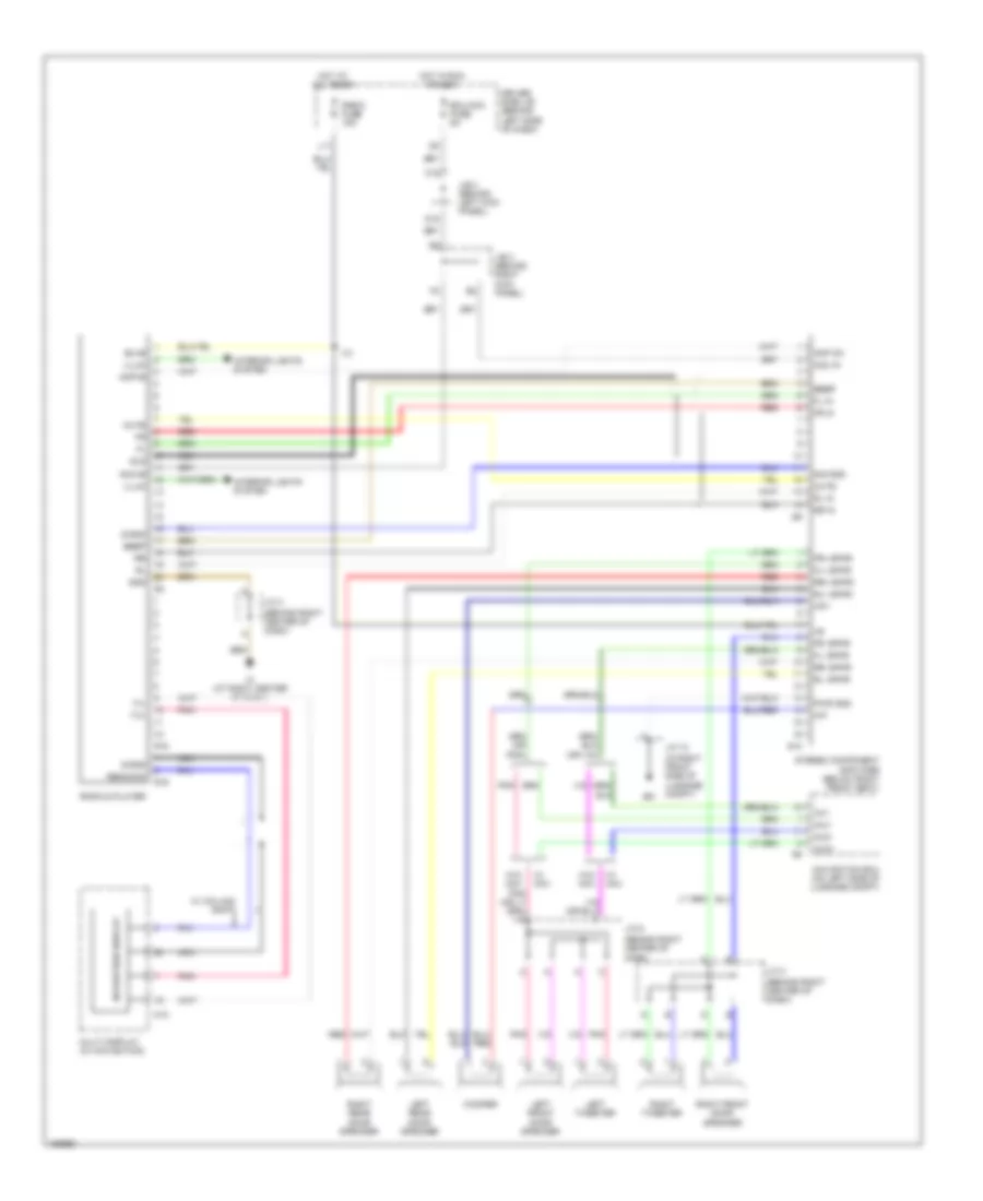 https://portal-diagnostov.com/license.html
Automotive Electricians Portal FZCO
Automotive Electricians Portal FZCO
https://portal-diagnostov.com/license.html
https://portal-diagnostov.com/license.html
Automotive Electricians Portal FZCO
Automotive Electricians Portal FZCOList of elements for 7-Speaker System Wiring Diagram for Toyota Avalon XLS 2004:
- (behind right center of dash)
- (in right front side of luggage compt)
- Acc in
- Acc+b
- Amp on
- Amp+b
- Aui+
- Aui-
- Auo+
- Auo-
- Beep
- Bu+b
- C15
- D15
- Driver side j/b (behind left side of dash)
- Ecu-acc fuse 5a
- Fl in
- Fl+ spkr
- Fl- spkr
- Fr in
- Fr+ spkr
- Fr- spkr
- Gnd
- Hot at all times
- Hot in run or acc
- I12
- Ih (at right center of dash)
- Illum
- Interior lights system
- J/b 3 (behind left kick panel)
- J/b 4 (behind right kick panel)
- J/c 10
- J/c 3
- J/c 6
- L11
- Left front door speaker
- Left rear door speaker
- Left tweeter
- M10
- Multi display (w/ navigation)
- Mute
- Navigation display
- Navigation ecu (on left side of luggage compt)
- Nca
- Pnk
- Pwr gnd
- R15
- R16
- Radio & player
- Radio fuse 15a
- Red
- Remocom
- Right front door speaker
- Right rear door speaker
- Right tweeter
- Rl in
- Rl+ spkr
- Rl- spkr
- Rr in
- Rr+ spkr
- Rr- spkr
- S-gnd
- S10
- Sig gnd
- Sld
- Stereo component amplifier (below right front seat)
- Tx+
- Tx-
- W/ column shift
- W/ nav
- W/o nav
- Wf+
- Wf-
- Woofer
SHIFT INTERLOCK
Shift Interlock Wiring Diagram for Toyota Avalon XLS 2004
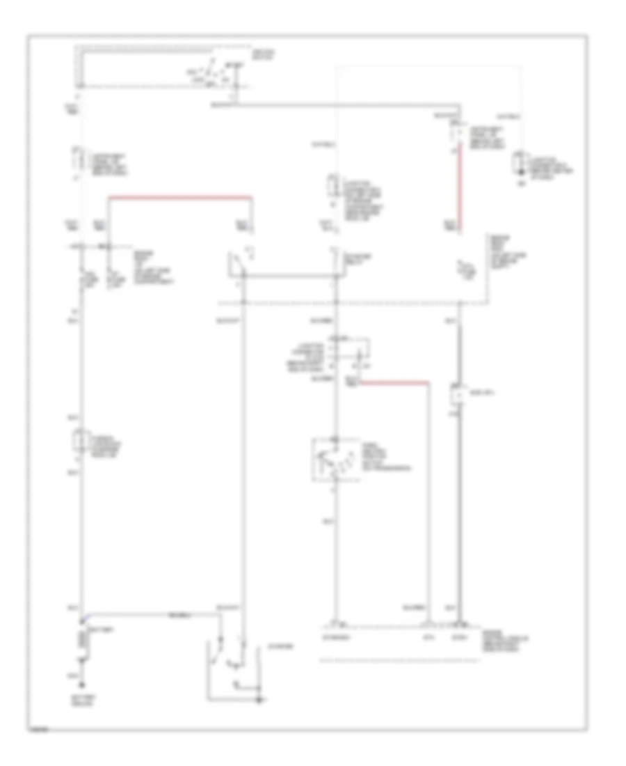 https://portal-diagnostov.com/license.html
Automotive Electricians Portal FZCO
Automotive Electricians Portal FZCO
https://portal-diagnostov.com/license.html
https://portal-diagnostov.com/license.html
Automotive Electricians Portal FZCO
Automotive Electricians Portal FZCOList of elements for Shift Interlock Wiring Diagram for Toyota Avalon XLS 2004:
- A19
- Acc
- Am2 fuse 25a
- Battery
- Battery ground
- Engine control module (behind right side of dash)
- Engine room j/b (on left side of engine compartment)
- Engine room r/b 2 (on left side of engine compt)
- Fusible link block (in engine room j/b)
- Ignition switch
- Instrument panel j/b (behind left end of dash)
- J51 b
- J52
- Junction connector 2 (on left side of engine compartment, near engine room j/b)
- Junction connector 5 (behind center of dash)
- Junction connector 51 & 52 (behind right end of dash)
- Lock
- Nca
- Off
- Park/ neutral position switch (on transmission)
- St fuse 30a
- Sta
- Sta fuse 7.5a
- Star/nsw
- Start
- Starter
- Starter relay
- Stsw
- Sub j/b 4
STARTING/CHARGING
Charging Wiring Diagram for Toyota Avalon XLS 2004
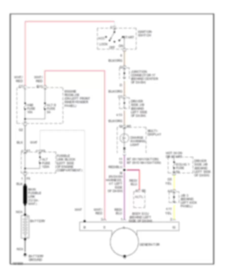 https://portal-diagnostov.com/license.html
Automotive Electricians Portal FZCO
Automotive Electricians Portal FZCO
https://portal-diagnostov.com/license.html
https://portal-diagnostov.com/license.html
Automotive Electricians Portal FZCO
Automotive Electricians Portal FZCOList of elements for Charging Wiring Diagram for Toyota Avalon XLS 2004:
- (w/ navigation) (w/o navigation)
- A11
- A13
- Acc
- Alt fuse 120a
- Alt-s fuse 5a
- Altl
- Am2 fuse 10a
- B11
- Battery
- Battery ground
- Body ecu (behind left side of dash)
- Charge warning light
- Driver side j/b (behind left side of dash)
- Ecu-ig 1 fuse 5a
- Engine room j/b (on left front inner fender panel)
- Fusible link block (left side of engine compartment)
- Generator
- Hot in on or start
- I8 (in dash harness, at left side of dash)
- Ignition switch
- J/b 3 (behind left kick panel)
- Junction connector 17 (behind center of dash)
- Lock
- M7 m7
- Multi- display
- Nca
- Off
- Start
Starting Wiring Diagram for Toyota Avalon XLS 2004
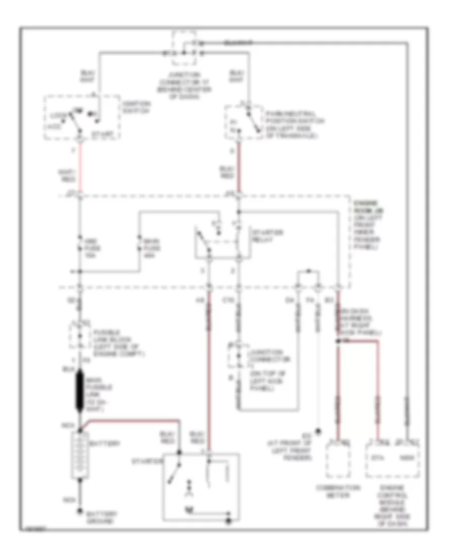 https://portal-diagnostov.com/license.html
Automotive Electricians Portal FZCO
Automotive Electricians Portal FZCO
https://portal-diagnostov.com/license.html
https://portal-diagnostov.com/license.html
Automotive Electricians Portal FZCO
Automotive Electricians Portal FZCOList of elements for Starting Wiring Diagram for Toyota Avalon XLS 2004:
- Acc
- Am2 fuse 10a
- Battery
- Battery ground
- Combination meter
- Ed (at front of left front fender)
- Engine control module (behind right side of dash)
- Engine engine room j/b room j/b (on left front inner fender panel)
- Fusible link block (left side of engine compt)
- Ignition switch
- Junction connector (on top of left kick panel)
- Junction connector 17 (behind center of dash)
- Lock
- Main fuse 40a
- Nca
- Nsw
- Off
- P/ n
- Park/neutral position switch (on left side of transaxle)
- Sta
- Start
- Starter
- Starter relay
SUPPLEMENTAL RESTRAINTS
Supplemental Restraints Wiring Diagram (1 of 2) for Toyota Avalon XLS 2004
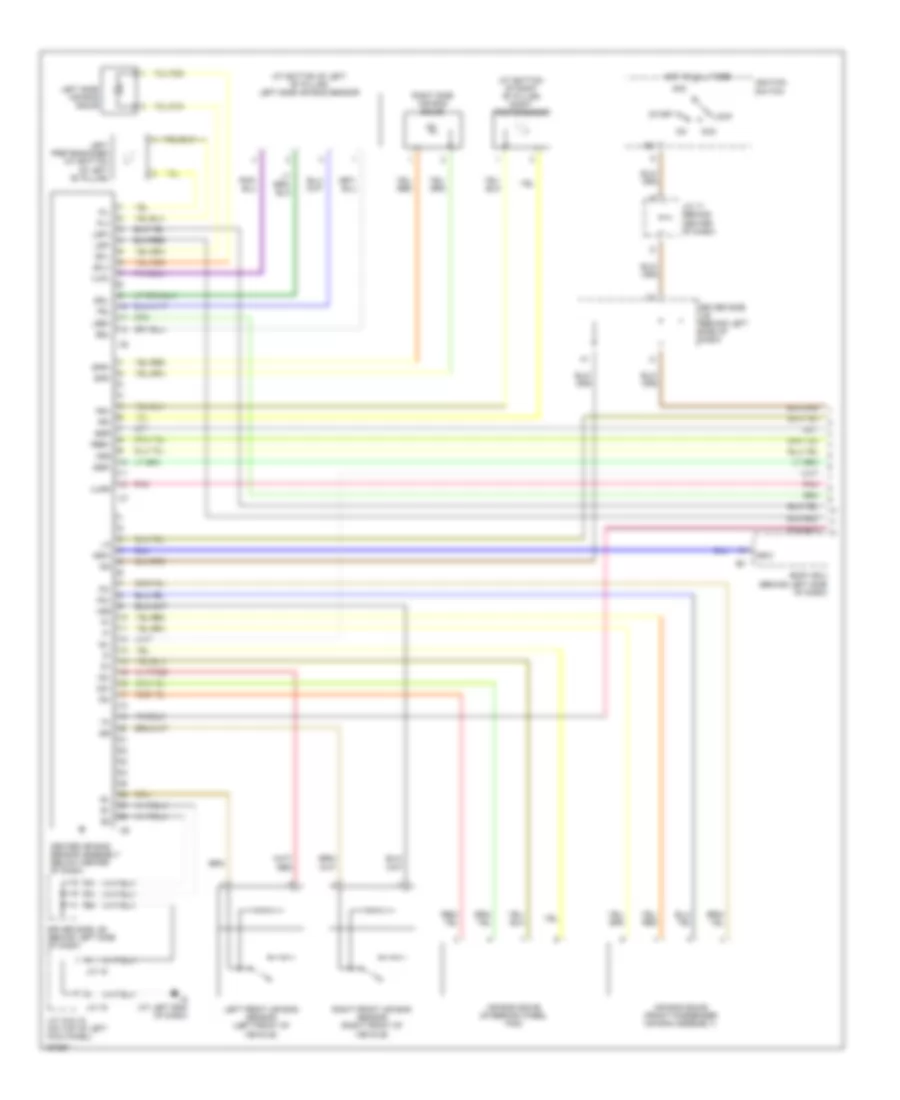 https://portal-diagnostov.com/license.html
Automotive Electricians Portal FZCO
Automotive Electricians Portal FZCO
https://portal-diagnostov.com/license.html
https://portal-diagnostov.com/license.html
Automotive Electricians Portal FZCO
Automotive Electricians Portal FZCOList of elements for Supplemental Restraints Wiring Diagram (1 of 2) for Toyota Avalon XLS 2004:
- (at bottom of left "b" pillar) left side air bag sensor
- (at bottom of right "b" pillar) right pretensioner
- +sl
- +sr
- -sl
- -sr
- Acc
- Air bag squib (front passenger air bag assembly)
- Air bag squib (steering wheel pad)
- Am2
- Body ecu (behind left side of dash)
- Center air bag sensor assembly (below center of dash)
- D2+
- D2-
- Driver side j/b (behind left side of dash)
- Esl
- Esr
- Fsl
- Fsr
- Gsw
- Hot at all times
- Ig (at left end of dash)
- Ig2
- Ignition switch
- J/c 15
- J/c 15 & 16 (on top of left kick panel)
- J/c 16
- J/c 17 (behind center of dash)
- Lbe+
- Left front air bag sensor (left front of vehicle)
- Left pretensioner (at bottom of left "b" pillar)
- Left side air bag squib
- Lock
- Lsp+
- Lsp-
- P2+
- P2-
- Pl+
- Pl-
- Pnk
- Pr+
- Pr-
- Rbe+
- Right front air bag sensor (right front of vehicle)
- Right side air bag squib
- Sfl+
- Sfl-
- Sfr+
- Sfr-
- Sil
- Ssl-
- Ssr-
- Start
- Vupl
- Vupr
Supplemental Restraints Wiring Diagram (2 of 2) for Toyota Avalon XLS 2004
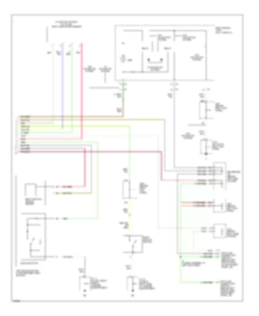 https://portal-diagnostov.com/license.html
Automotive Electricians Portal FZCO
Automotive Electricians Portal FZCO
https://portal-diagnostov.com/license.html
https://portal-diagnostov.com/license.html
Automotive Electricians Portal FZCO
Automotive Electricians Portal FZCOList of elements for Supplemental Restraints Wiring Diagram (2 of 2) for Toyota Avalon XLS 2004:
- (at bottom of right "b" pillar) right side air bag sensor
- A12
- A13
- Buckle switch
- C18
- Data link connector 2 (partial) (behind left side of dash, instrument panel j/b)
- Data link connector 3 (partial) (behind left side of dash, on instrument panel j/b)
- Driver side j/b (behind left side of dash)
- E18
- G20
- I10
- I4 (in dash harness, at left kick panel)
- J/b 3 (behind left kick panel)
- J/b 4 (behind right kick panel)
- J/c 10 (in right front side of luggage compartment)
- J/c 11 (in left front side of luggage compartment)
- J/c 5 (behind right side of dash)
- J/c 9 (on top of right kick panel)
- Left buckle switch (in driver's seat belt buckle)
- Pnk
- Relay
- Right buckle switch
- Seat position air bag sensor
- Srs
- Srs warning light (multi display)
- W/ navigation system
- W/navigation system
- W/o navigation system
TRANSMISSION
A/T Wiring Diagram (1 of 2) for Toyota Avalon XLS 2004
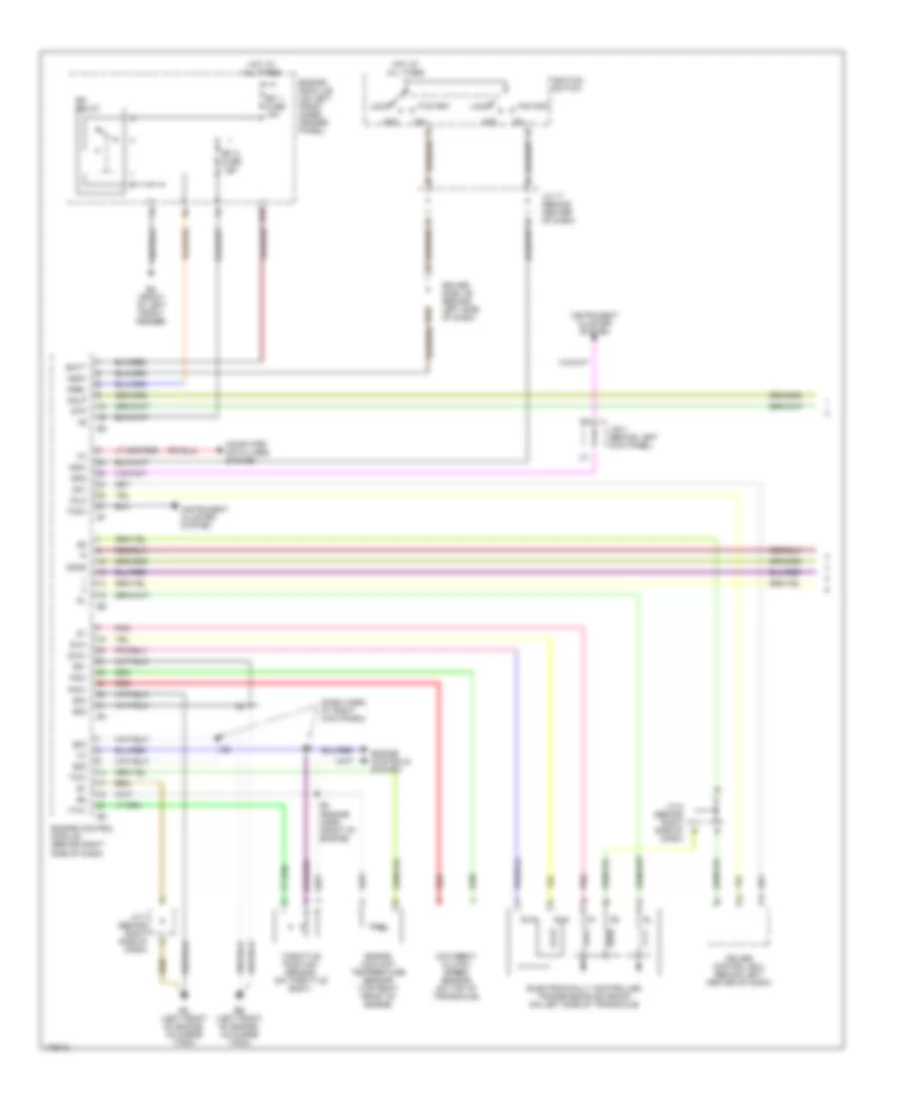 https://portal-diagnostov.com/license.html
Automotive Electricians Portal FZCO
Automotive Electricians Portal FZCO
https://portal-diagnostov.com/license.html
https://portal-diagnostov.com/license.html
Automotive Electricians Portal FZCO
Automotive Electricians Portal FZCOList of elements for A/T Wiring Diagram (1 of 2) for Toyota Avalon XLS 2004:
- (dash harn, at right kick panel)
- Acc
- B10
- B12
- Batt
- Computer data lines system
- Cruise control ecu (behind left center of dash)
- Dash)
- Driver side j/b (behind left side of dash)
- E01
- E02
- E03
- E04
- E05
- E2 (engine harn, front of engine)
- Eb (left front of engine, on surge tank)
- Ec (left front of engine, on surge tank)
- Ed (front of left front fender)
- Efi 1 fuse 15a
- Efi 2 fuse 7.5a
- Efi relay
- Electronically controlled transmission solenoid (on left side of transaxle)
- Engine control module (behind right side of dash)
- Engine controls system
- Engine coolant temperature sensor (top right front of engine)
- Engine room j/b (on left front inner fender panel)
- Hot at all times
- I22
- I23
- Idlo
- Ignition switch
- Igsw
- Instrument cluster system
- J/b 3 (behind left kick panel)
- J/c 17 (behind center of dash)
- J/c 7 (behind right side of dash)
- J/c 8 (behind right side of b
- Lock
- Mrel
- Nc2+
- Nc2-
- Nsw
- O/d direct clutch speed sensor (on top of transaxle)
- Od1
- Odlp
- Odms
- Pnk
- Red
- Sln+
- Sln-
- Spd
- Start
- Stp
- Tach
- Throttle position sensor (on throttle body)
- Thw
- Vta1
A/T Wiring Diagram (2 of 2) for Toyota Avalon XLS 2004
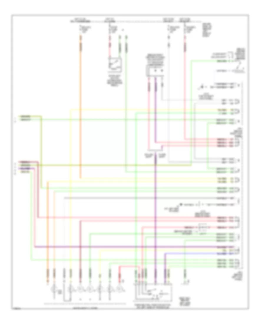 https://portal-diagnostov.com/license.html
Automotive Electricians Portal FZCO
Automotive Electricians Portal FZCO
https://portal-diagnostov.com/license.html
https://portal-diagnostov.com/license.html
Automotive Electricians Portal FZCO
Automotive Electricians Portal FZCOList of elements for A/T Wiring Diagram (2 of 2) for Toyota Avalon XLS 2004:
- (behind center of dash)
- (behind right center of dash) (column shift) a/t indicator light diode 2
- (below center console) o/d main switch
- A16
- A17
- A18
- B13
- B17
- Body ecu (behind left side of dash)
- C11
- C15
- C16
- C18
- C20
- Column shift
- D11
- D15
- D16
- D18
- D20
- Driver side j/b (behind left side of dash)
- Ecu-acc fuse 5a
- Ecu-ig 2 fuse 10a
- F16
- F18
- Floor shift
- G16
- G17
- G18
- Gauge 2 fuse 10a
- H18
- Hot at all times
- Hot in on or accy
- Hot in on or start
- Hot w/ ig1 relay energized
- Ig (at left end of dash)
- Instrument cluster
- J/b 3 (behind left kick panel)
- J/b 4 (behind right kick panel)
- J/c 17
- J/c 5 (behind right side of dash)
- J/c 9 (top of right kick panel)
- O/d off
- Park/neutral position switch (on left side of transaxle)
- Red
- Stop fuse 15a
- Stoplight switch (on bracket, above brake pedal)
TRUNK, TAILGATE, FUEL DOOR
Trunk Release Wiring Diagram for Toyota Avalon XLS 2004
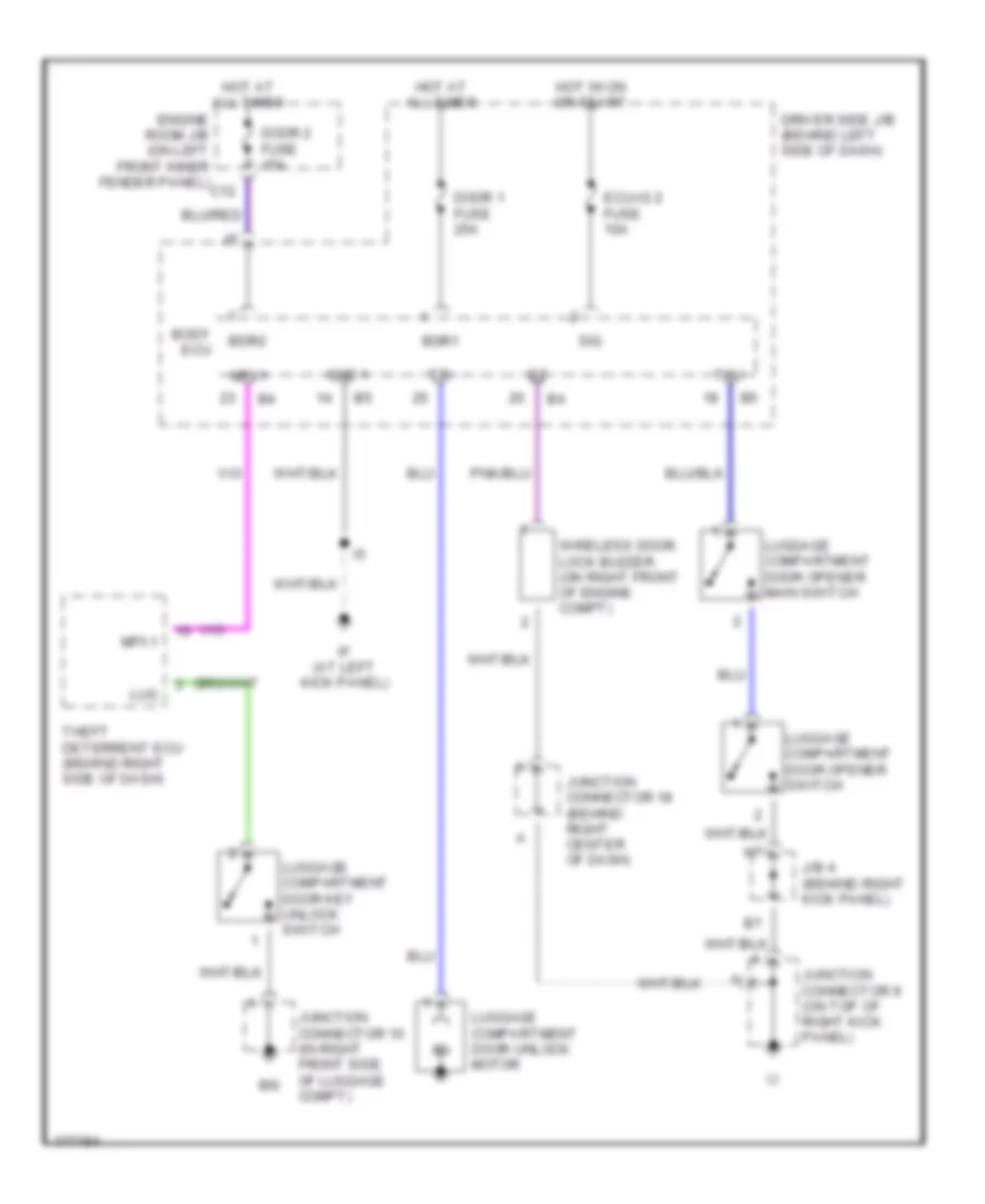 https://portal-diagnostov.com/license.html
Automotive Electricians Portal FZCO
Automotive Electricians Portal FZCO
https://portal-diagnostov.com/license.html
https://portal-diagnostov.com/license.html
Automotive Electricians Portal FZCO
Automotive Electricians Portal FZCOList of elements for Trunk Release Wiring Diagram for Toyota Avalon XLS 2004:
- Bdr1
- Bdr2
- Body ecu
- Door 1 fuse 25a
- Door 2 fuse 15a
- Driver side j/b (behind left side of dash)
- Ecu-ig 2 fuse 10a
- Engine room j/b (on left front inner fender panel) c12
- Gnd 1
- Hot at all times
- Hot in on or start
- If (at left kick panel)
- J/b 4 (behind right kick panel)
- Junction connector 10 (in right front side of luggage compt)
- Junction connector 18 (behind right center of dash)
- Junction connector 9 (on top of right kick panel)
- Lug
- Luggage compartment door key unlock switch
- Luggage compartment door opener main switch
- Luggage compartment door opener switch
- Luggage compartment door unlock motor
- Mpx1
- Sig
- Theft deterrent ecu (behind right side of dash)
- Tku
- Tr+
- Wireless door lock buzzer (on right front of engine compt)
WARNING SYSTEMS
Warning Systems Wiring Diagram for Toyota Avalon XLS 2004
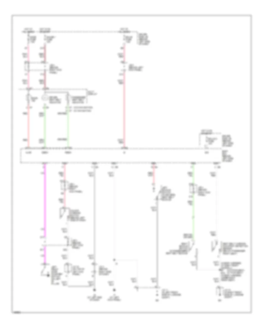 https://portal-diagnostov.com/license.html
Automotive Electricians Portal FZCO
Automotive Electricians Portal FZCO
https://portal-diagnostov.com/license.html
https://portal-diagnostov.com/license.html
Automotive Electricians Portal FZCO
Automotive Electricians Portal FZCOList of elements for Warning Systems Wiring Diagram for Toyota Avalon XLS 2004:
- (w/ navigation)
- (w/o navigation)
- (w/o pwr seat) (w/ pwr seat)
- A11
- Ajar
- Body ecu (behind left side of dash)
- C18
- D10
- D14
- D17
- D22
- Dbew
- Dbkl
- Dcty
- Dome fuse 7.5a
- Door ind
- Driver seat belt indicator
- Driver side j/b (behind left side of dash)
- E17
- Ecu-b fuse 7.5a
- Ecu-ig 2 fuse 10a
- F13
- F18
- Gauge 1 fuse 10a
- Gnd1
- Gnd2
- Hot at all times
- Hot in on or start
- If (at left kick panel)
- Ig (at left end of dash)
- J/b 3 (behind left kick panel)
- J/b 4 (behind right kick panel)
- J/c 10 (in right front side of luggage compt)
- J/c 11 (in left front side of luggage compt)
- J/c 16 (on top of left kick panel)
- J/c 4 (behind right side of dash)
- Ksw
- Left buckle switch (in driver's seat belt buckle)
- Left front door courtesy switch (on left "b" pillar)
- Multi display
- Passenger seat belt indicator
- Pbew
- Pbkl
- Red
- Right buckle switch (in passenger's seat belt buckle)
- Seat
- Seat belt warning occupant detection sensor (below passenger front seat)
- Sig
- Unlock warning switch (behind left side of dash)
WIPER/WASHER
Wiper/Washer Wiring Diagram, with Auto Wiper System for Toyota Avalon XLS 2004
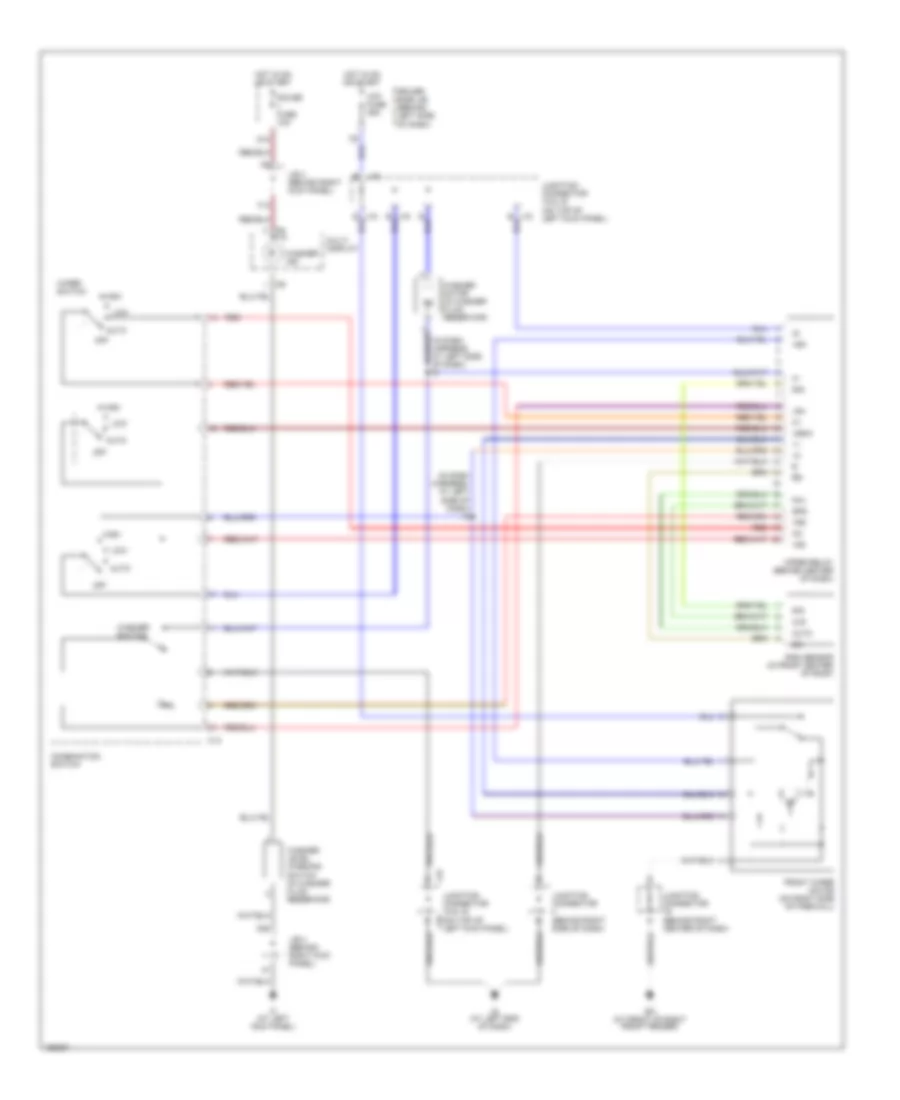 https://portal-diagnostov.com/license.html
Automotive Electricians Portal FZCO
Automotive Electricians Portal FZCO
https://portal-diagnostov.com/license.html
https://portal-diagnostov.com/license.html
Automotive Electricians Portal FZCO
Automotive Electricians Portal FZCOList of elements for Wiper/Washer Wiring Diagram, with Auto Wiper System for Toyota Avalon XLS 2004:
- (in dash harness, at left side of dash) i9
- +2s
- +sm
- +ssw
- Auto
- B j15
- B j16
- C14
- Combination switch
- D10
- D20
- Driver side j/b (behind left side of dash)
- Ea (at front of right front fender)
- F13
- Front wiper motor (on right side of firewall)
- Gauge fuse 10a
- High
- Hot in on or start
- If (at left kick panel)
- Ig (at left end of dash)
- J/b 4 (behind right kick panel)
- J15
- J15 b
- J16
- Junction connector (behind right center of dash)
- Junction connector (behind right side of dash)
- Junction connector 15 & 16 (on top of left kick panel)
- Junction connector 15 & 16 (on top of left kick panel) j16
- Low
- Multi display
- Off
- Pa1
- Rain sensor (in front center of roof)
- Red
- Sig
- Spd
- Vr1
- Vr2
- Washer ind
- Washer level warning switch (in washer fluid reservoir)
- Washer motor (in washer fluid reservoir)
- Washer switch
- Wip
- Wip fuse 25a
- Wiper relay (behind center of dash)
- Wiper switch
Wiper/Washer Wiring Diagram, without Auto Wiper System for Toyota Avalon XLS 2004
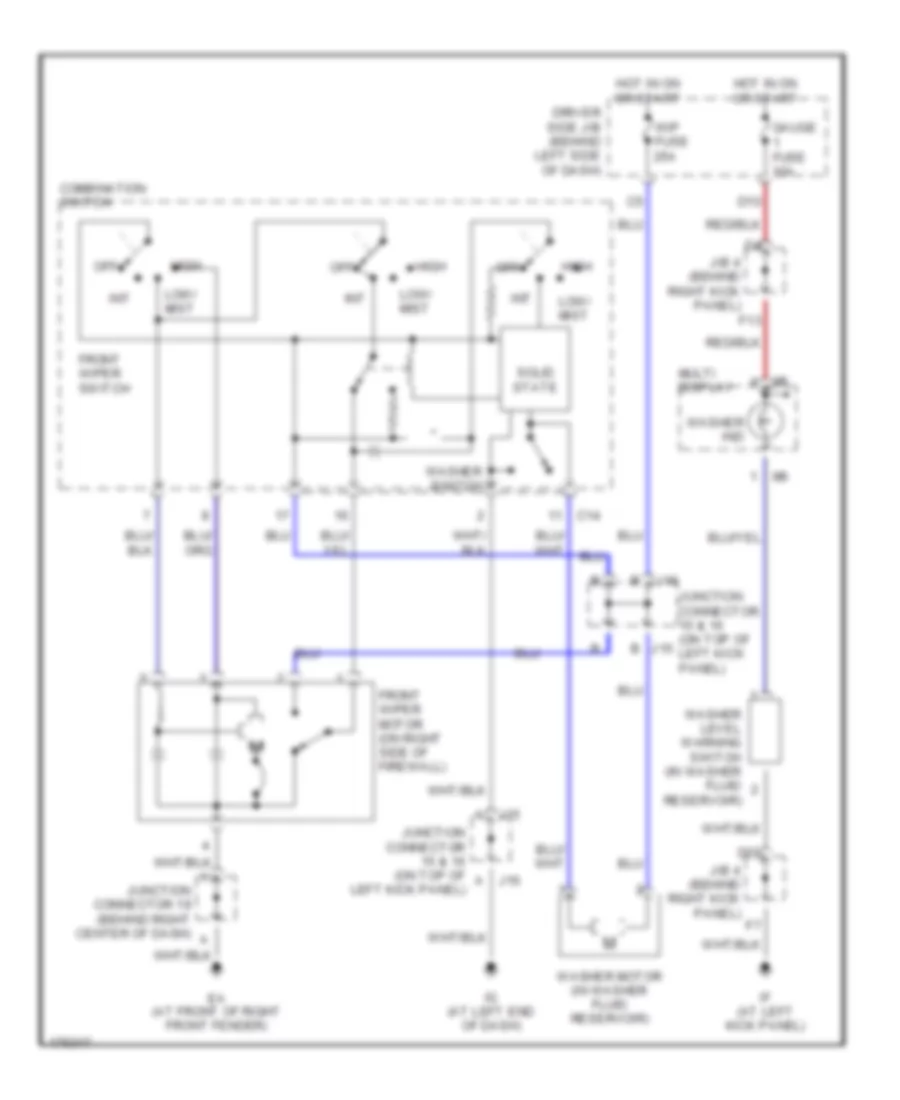 https://portal-diagnostov.com/license.html
Automotive Electricians Portal FZCO
Automotive Electricians Portal FZCO
https://portal-diagnostov.com/license.html
https://portal-diagnostov.com/license.html
Automotive Electricians Portal FZCO
Automotive Electricians Portal FZCOList of elements for Wiper/Washer Wiring Diagram, without Auto Wiper System for Toyota Avalon XLS 2004:
- A j15
- A j16
- B j15
- C14
- Combination switch
- D10
- D20
- Driver side j/b (behind left side of dash)
- Ea (at front of right front fender)
- F13
- Front wiper motor (on right side of firewall)
- Front wiper switch
- Gauge fuse 10a
- High
- Hot in on or start
- If (at left kick panel)
- Ig (at left end of dash)
- Int
- J/b 4 (behind right kick panel)
- J16
- Junction connector 15 & 16 (on top of left kick panel)
- Junction connector 19 (behind right center of dash)
- Low/ mist
- Multi display
- Off
- Solid state
- Washer ind
- Washer level warning switch (in washer fluid reservoir)
- Washer motor (in washer fluid reservoir)
- Washer switch
- Wip fuse 25a

 Čeština
 Dansk
Dansk Deutsch
 Ελληνικά
 English
 English
 Español
 Suomi
Suomi Français
 Français
 עברית
עברית Hrvatski
 Magyar
 Italiano
 日本語
日本語 한국어
한국어 Nederlands
 Polski
 Português
 Português
 Română
 Русский
 Slovenčina
 Slovenščina
 Svenska
 中文 (中国)
