TRANSMISSION
A/T Wiring Diagram for Audi 100 CS 1994

List of elements for A/T Wiring Diagram for Audi 100 CS 1994:
- (below left gearbox support)
- (left heel panel, below rear seat)
- * *
- * fwd ** quattro
- 14a
- 15a
- 1995 vftc c
- 20a
- 50a
- 50z
- 87a
- Abs control module
- Acc
- Acc on
- Air conditioning system
- Automatic trans- mission console light
- Auxilliary relay panel 1 (left i/p)
- Auxilliary relay panel 2 (left kick panel)
- B10
- B11
- B12
- B13
- Battery positive terminal
- Brake light switch (on pedal cluster)
- Central electric panel (left i/p)
- Central locking/ alarm system/ interior light delay control module (below rear seat)
- Connector station 1
- Connector station 3
- Cruise control system
- Data link connector
- Engine control module (behind right kick panel)
- Exterior lights system
- Fuse 10a
- Fuse 15a
- Fuse 5a
- Fuse panel (left i/p)
- G131 (on intake manifold)
- G200 (lower left "a" pillar)
- Generator terminal d+
- Hot at all times
- Ignition switch
- Instrument cluster system
- Interior lights system
- Kick down switch (on throttle valve body, or cable)
- Multi-function switch
- Mv1
- Mv2
- Mv3
- Nca
- Not used
- Off
- P/n
- Park/neutral position relay
- Protection diode
- Red
- Red/
- Selector lever light relay
- Shift lock control module
- Shift lock solenoid (front of gear selector)
- Solenoid valves
- Start
- Starter terminal
- T16
- Transmission control module (behind right kick panel)
- Transmission fluid temperature sensor
- Transmission selector lever display
- Valve body
- Vehicle speed sensor (on right of gearbox housing)
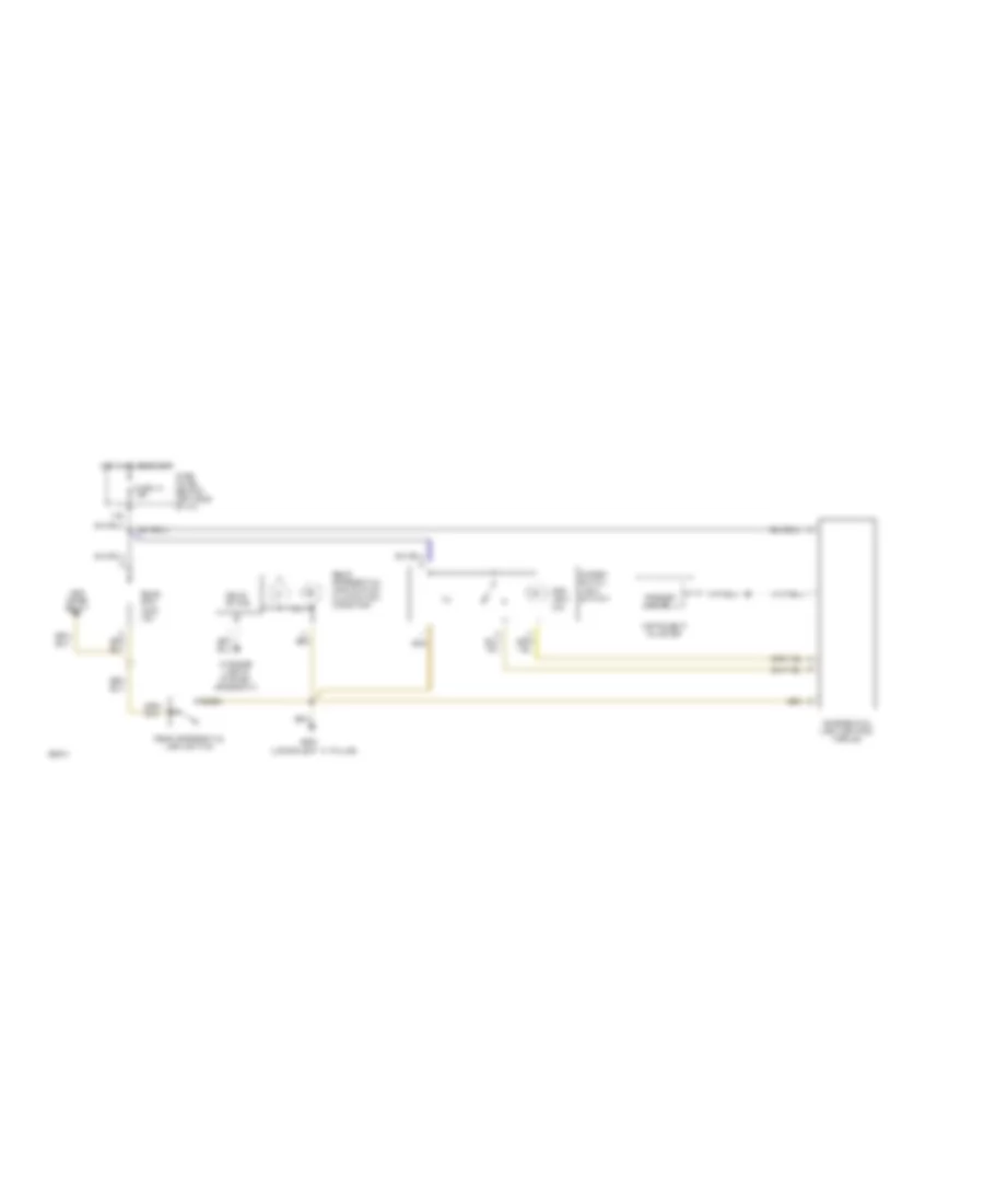
Differential Lock Wiring Diagram, Quattro for Audi 100 CS 1994
List of elements for Differential Lock Wiring Diagram, Quattro for Audi 100 CS 1994:
- (lower left "a" pillar)
- 14a
- Abs combi relay
- Cluster
- Diff. lock ind.
- Differ- ential lock switch
- Differential lock control
- Fuse 14 15a
- Fuse panel (behind left side of i/p)
- G200
- Hot in on or start
- Ill.
- Instrument
- Interior lights system (rheostat)
- Module
- Rear diff. lock ind.
- Rear differential lock switch
- Rear differential lock switch illumination/ indicator
- Solid state
- Speedo- meter