TRANSMISSION
4.9L
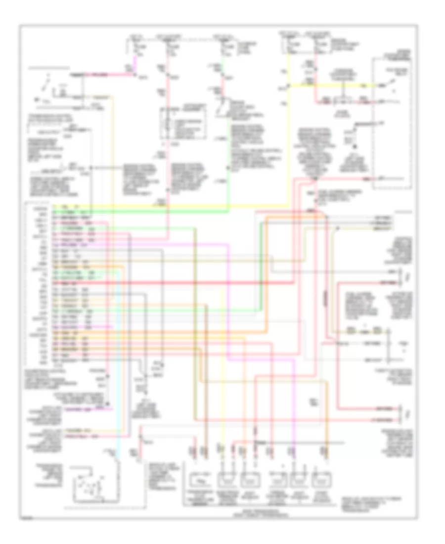
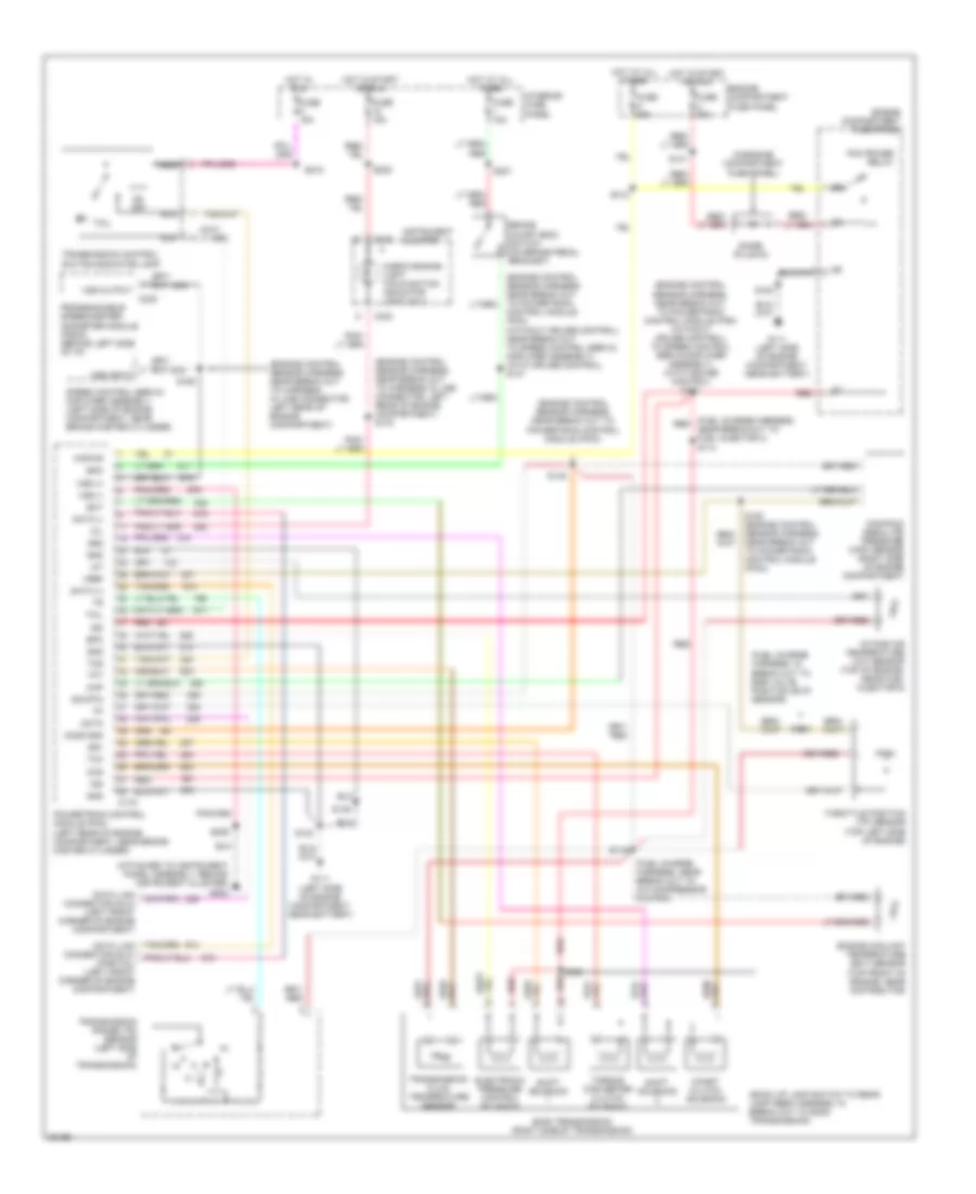
4.9L, Transmission Wiring Diagram for Ford Cutaway E350 1996

List of elements for 4.9L, Transmission Wiring Diagram for Ford Cutaway E350 1996:
- connector (dlc) (partial) (below left side of i/p)
- (attached to instrument panel assembly, behind instrument cluster) g202
- (back up lamp switch to rear lamp feed harness, in break out to e40d transmission)
- (dash engine gage feed harness, near break out to a/c compressor clutch)
- (dash engine gage feed harness, near break out to airb solenoid)
- (dash engine gage feed harness, near break out to engine oil pressure switch) s119
- (engine control sensor harness, near break out to harness in line connector, left rear of engine compartment)
- (engine control sensor harness, near break out to powertrain control module (pcm))
- (engine control sensor harness, near break out; to powertrain control module (pcm) (without cruise control) to speed control servo/amplifier assembly) (with cruise control) s151
- (fuel charge harness, near break out to fuel injector 2)
- (in engine compartment fuse panel)
- (left side of engine compartment, near battery) g111
- Boo
- Brake on/off (boo) switch (on brake pedal bracket)
- Bus +
- Bus -
- C143
- C230
- C233
- Ccs
- Check engine light "malfunction indicator lamp (mil)"
- Coast clutch solenoid
- Control module (pcm) (without cruise control) near break out to speed control servo/ amplifier assembly) (with cruise control) s147
- Data link
- Diode (plug-in)
- E40d transmission (right side of transmission)
- Ect
- Electronic pressure control solenoid
- Engine compartment fuse panel
- Engine coolant temperature (ect) sensor (top front of engine, on heater outlet elbow)
- Epc
- Fuse 15a
- Fuse c 30a
- Fuse u 30a
- G111 (left side of engine compartment, near battery)
- Gen scan
- Gnd
- Hot at all times
- Hot in run
- Hot in start or run
- Iat
- Instrument cluster
- Intake air temperature (iat) sensor (center of engine compartment, part of clean air tube)
- Interior fuse panel
- Kapwr
- Maf
- Maf rtn
- Mass air flow (maf) sensor (center of engine compartment)
- Mil
- N d
- Nca
- Od off
- Pcm power relay
- Power
- Powertrain control module (pcm) (left rear of engine compartment, near brake master cylinder)
- Programmable speedometer/ odometer module (psom) (behind left side of i/p)
- Red
- S100
- S104
- S116
- S117
- S120
- S133
- S140
- S141
- S145
- S146
- S153
- S160
- S187
- S206
- S208
- S218
- S221
- Shift solenoid
- Sig rtn
- Speed control servo/ amplifier assembly (left side of engine compartment, near brake master cylinder)
- Ss1
- Ss2
- Tcc
- Tcil
- Tcs
- Tft
- Throttle position (tp) sensor (top left side of engine)
- Torque converter clutch solenoid
- Transmission control switch/indicator lamp
- Transmission fluid temperature sensor
- Transmission range (tr) sensor (left side of transmission)
- Vref
- Vss
- Vss input
- Vss output
5.8L
5.8L, Transmission Wiring Diagram, Federal over 8600 GVW for Ford Cutaway E350 1996
List of elements for 5.8L, Transmission Wiring Diagram, Federal over 8600 GVW for Ford Cutaway E350 1996:
- (attached to instrument panel assembly, behind instrument cluster) g202
- (back up lamp switch to rear lamp feed harness, in break out to e40d transmission)
- (engine control sensor harness, near break out to harness in line connector, left rear of engine compartment)
- (engine control sensor harness, near break out to harness in line connector, left rear of engine compartment) s143
- (engine control sensor harness, near break out; to powertrain control module (pcm) (without cruise control) to speed control servo/amplifier assembly) (with cruise control) s151
- (fuel charge harness, near break out to evaporative emissions (evap) canister purge valve)
- (fuel charge harness, near break out to fuel injector 2) s114
- (in engine compartment fuse panel)
- Boo
- Brake on/off (boo) switch (on brake pedal bracket)
- C175
- C230
- C233
- Ccs
- Check engine light "malfunction indicator light (mil)"
- Coast clutch solenoid
- Control module (pcm) (without cruise control) near break out to speed control servo/ amplifier assembly) (with cruise control) s147
- Data
- Data (+)
- Data (-)
- Data link connector (dlc) (left front corner of engine compartment)
- Diode (plug-in)
- E40d transmission (right side of transmission)
- Ect
- Electronic pressure control solenoid
- Engine compartment fuse panel
- Engine coolant temperature (ect) sensor (top front of engine, near distributor, on heater tube)
- Epc
- Fuse 15a
- Fuse c 30a
- Fuse u 30a
- G111 (left side of engine compartment, near battery)
- Gnd
- Ho2s gnd
- Hot at all times
- Hot in run
- Hot in start or run
- Iat
- Ign
- Instrument cluster
- Intake air temperature (iat) sensor (right side of engine, near fuel injector 1)
- Interior fuse panel
- Kapwr
- Manifold absolute pressure (map) sensor (right side of engine compartment)
- Map
- Mil
- N d
- Nca
- Od off
- Pcm power relay
- Powertrain control module (pcm) (left rear of engine compartment, near brake master cylinder)
- Programmable speedometer/ odometer module (psom) (behind left side of i/p)
- Red
- S104
- S116
- S118
- S120
- S133
- S140
- S141
- S146
- S153
- S160
- S206
- S208
- S218
- S221
- Shift solenoid
- Sig rtn
- Speed control servo/ amplifier assembly (left side of engine compartment, near brake master cylinder)
- Ss1
- Ss2
- Tcc
- Tcil
- Tcs
- Tft
- Throttle position (tp) sensor (right front of engine)
- Torque converter clutch solenoid
- Transmission control switch/indicator lamp
- Transmission fluid temperature sensor
- Transmission range (tr) sensor (left side of transmission)
- Vref
- Vss (+)
- Vss (-)
- Vss input
- Vss output
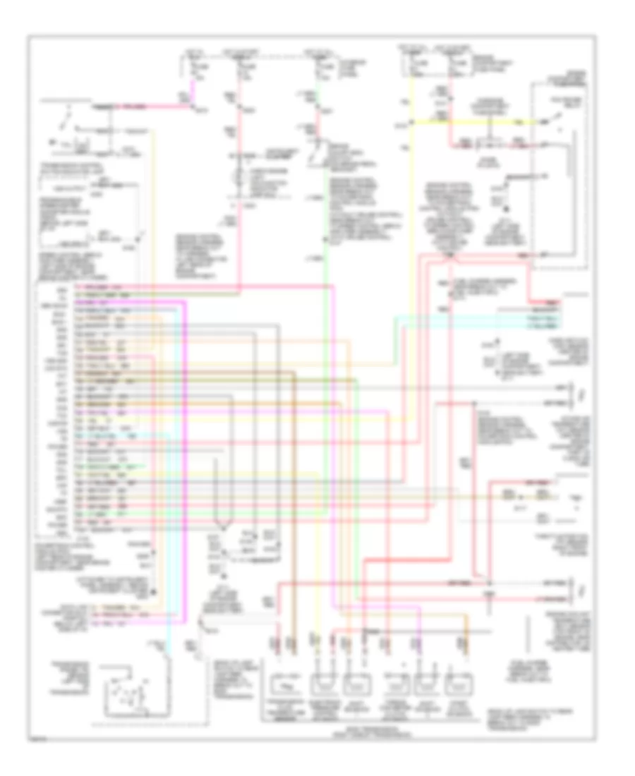
5.8L, Transmission Wiring Diagram, Federal under 8600 GVW & Calif. for Ford Cutaway E350 1996
List of elements for 5.8L, Transmission Wiring Diagram, Federal under 8600 GVW & Calif. for Ford Cutaway E350 1996:
- connector (dlc) (partial) (below left side of i/p)
- (attached to instrument panel assembly, behind instrument cluster) g202
- (back up lamp switch to rear lamp feed harness, in break out to e40d transmission)
- (engine control sensor harness, near break out to harness in line connector, left rear of engine compartment)
- (engine control sensor harness, near break out; to powertrain control module (pcm) (without cruise control) to speed control servo/amplifier assembly) (with cruise control) s151
- (fuel charge harness, near break out to fuel injector 2)
- (fuel charge harness, near break out to fuel injector 2) s114
- (in engine compartment fuse panel)
- (left side of engine compartment, near battery) g111
- Boo
- Brake on/off (boo) switch (on brake pedal bracket)
- Bus +
- Bus -
- C143
- C230
- C233
- Ccs
- Check engine light "malfunction indicator lamp (mil)"
- Coast clutch solenoid
- Control module (pcm) (without cruise control) near break out to speed control servo/ amplifier assembly) (with cruise control) s147
- Data link
- Diode (plug-in)
- E40d transmission (right side of transmission)
- Ect
- Electronic pressure control solenoid
- Engine compartment fuse panel
- Engine coolant temperature (ect) sensor (top front of engine, near distributor, on heater tube)
- Epc
- Fuse 15a
- Fuse c 30a
- Fuse u 30a
- G111 (left side of engine compartment, near battery)
- Gen scan
- Gnd
- Hot at all times
- Hot in run
- Hot in start or run
- Iat
- Instrument cluster
- Intake air temperature (iat) sensor (center of engine compartment, part of clean air tube)
- Interior fuse panel
- Kapwr
- Maf
- Maf rtn
- Mass air flow (maf) sensor (center of engine compartment)
- Mil
- N d
- Nca
- Od off
- Pcm power relay
- Power
- Powertrain control module (pcm) (left rear of engine compartment, near brake master cylinder)
- Programmable speedometer/ odometer module (psom) (behind left side of i/p)
- Red
- S100
- S104
- S117
- S120
- S133
- S140
- S141
- S145 (engine control sensor harness, near break out to powertrain control module(pcm))
- S146
- S153
- S160
- S187
- S206
- S208
- S218
- S221
- Shift solenoid
- Sig rtn
- Speed control servo/ amplifier assembly (left side of engine compartment, near brake master cylinder)
- Ss1
- Ss2
- Tcc
- Tcil
- Tcs
- Tft
- Throttle position (tp) sensor (right front of engine)
- Torque converter clutch solenoid
- Transmission control switch/indicator lamp
- Transmission fluid temperature sensor
- Transmission range (tr) sensor (left side of transmission)
- Vref
- Vss
- Vss gnd
- Vss input
- Vss output
7.3L
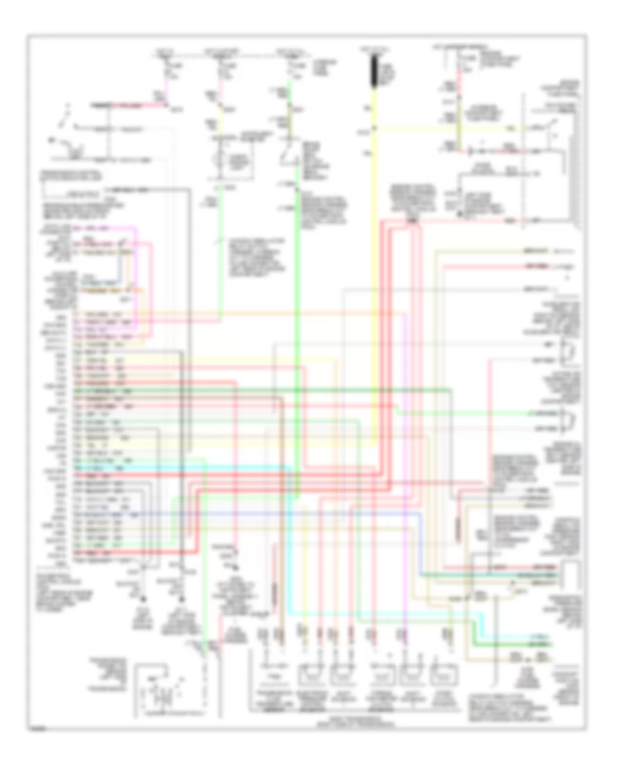
7.3L DI Turbo Diesel, Transmission Wiring Diagram for Ford Cutaway E350 1996
List of elements for 7.3L DI Turbo Diesel, Transmission Wiring Diagram for Ford Cutaway E350 1996:
- (engine control sensor harness, near break out to a/c compressor clutch)
- (engine control sensor harness, near break out to powertrain control module (pcm)) s145
- (engine control sensor harness, near break out to powertrain control module (pcm)) s151
- (fuel charge harness)
- (in engine compartment fuse panel)
- (left side of engine compartment, near battery) g111
- (window regulator relay switch harness, in break out to harness in-line connector, left rear of engine compartment)
- (window regulator relay switch harness, near break out to harness in-line connector, left rear of engine compartment)
- Accelerator pedal (ap) position sensor (behind left side of i/p, above accelerator pedal)
- Acel pdl
- Auxiliary powertrain control connector (partial) (behind left side of i/p)
- Baro
- Barometric pressure (baro) sensor (behind left side of i/p)
- Boo
- Brake on/off (boo) switch (on brake pedal bracket)
- C230
- C233
- Cam
- Cam gnd
- Camshaft position (cmp) sensor (front of engine)
- Ccs
- Check engine light
- Chk eng
- Coast clutch solenoid
- Data (+)
- Data (-)
- Data link connector (dlc) (partial) (below left side of i/p)
- Diode (plug-in)
- E40d transmission (right side of transmission)
- Electronic pressure control solenoid
- Eng oil
- Engine compartment fuse panel
- Engine oil temperature (eot) sensor (center left side of engine)
- Epc
- Fuse 15a
- Fuse u 30a
- G111 (left side of engine compartment, near battery)
- G112 (left side of engine)
- G202 (attached to instrument panel assembly, behind instrument cluster)
- Gen data
- Gnd
- Hot at all times
- Hot in run
- Hot in start or run
- Iat
- Instrument cluster
- Intake air temperature (iat) sensor (center of engine compartment)
- Interior fuse panel
- Kapwr
- Manifold absolute pressure (map) sensor (right side of engine compartment)
- Map
- N d
- Nca
- Od off
- Pcm power relay
- Powertrain control module (pcm) (left rear of engine compartment, near brake master cylinder)
- Programmable speedometer/ odometer module (psom) (behind left side of i/p)
- Pwr in
- Red
- S133
- S141
- S146
- S147 (engine control sensor harness, near break out to powertrain control module (pcm))
- S150
- S153
- S187
- S190
- S192 (fuel charge harness)
- S206
- S208
- S218
- S221
- S271
- S272
- S273
- S274
- Shift solenoid
- Sig rtn
- Ss1
- Ss2
- Tcc
- Tcil
- Tcs
- Tft
- Torque converter clutch solenoid
- Transmission control switch/indicator lamp
- Transmission fluid temperature sensor
- Transmission range (tr) sensor (left side of transmission)
- Vref
- Vss
- Vss gnd
- Vss output
7.5L
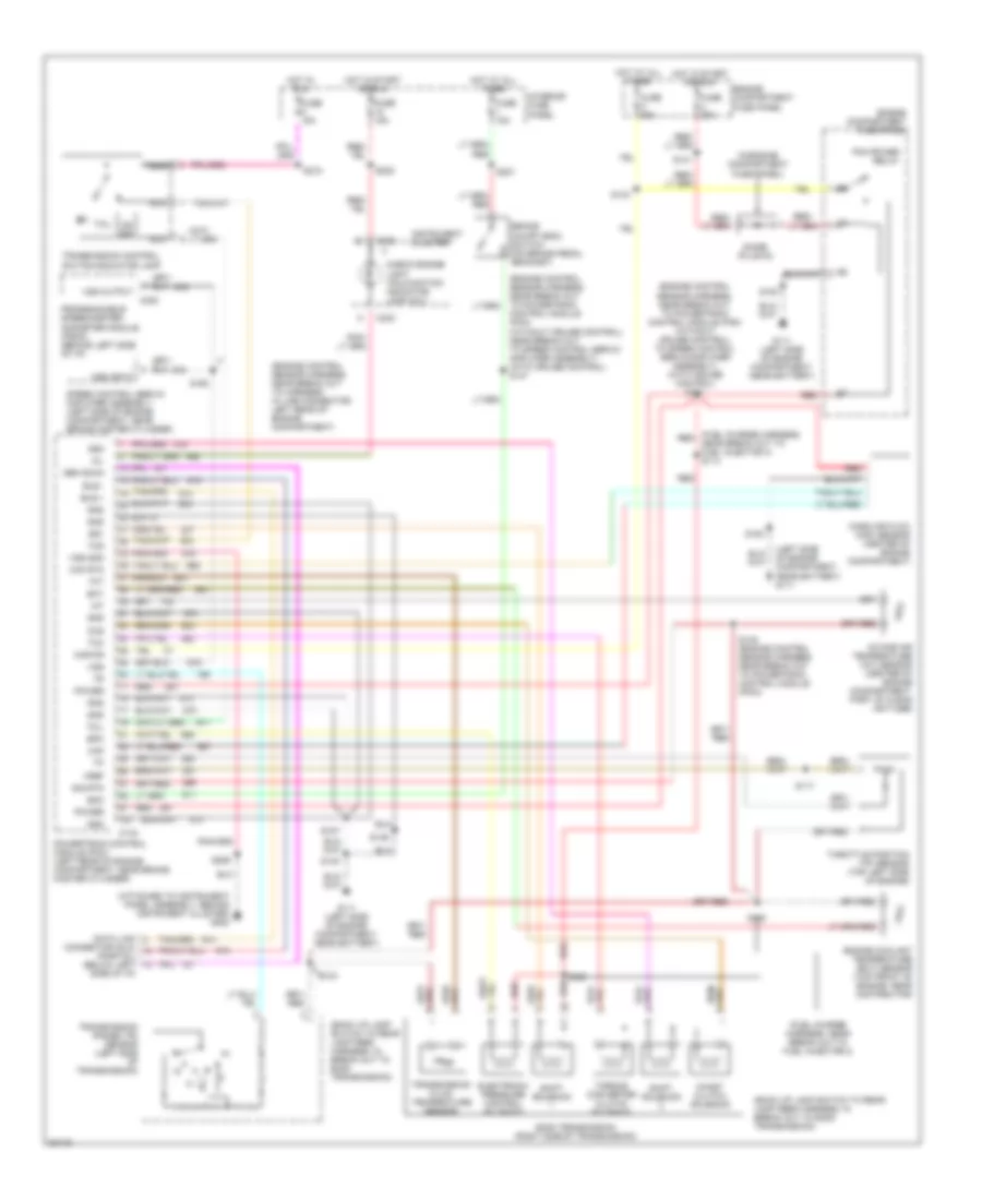
7.5L, Transmission Wiring Diagram, California for Ford Cutaway E350 1996
List of elements for 7.5L, Transmission Wiring Diagram, California for Ford Cutaway E350 1996:
- connector (dlc) (partial) (below left side of i/p)
- (attached to instrument panel assembly, behind instrument cluster) g202
- (back up lamp switch to rear lamp feed harness, in break out to e40d transmission)
- (engine control sensor harness, near break out to harness in line connector, left rear of engine compartment)
- (engine control sensor harness, near break out; to powertrain control module (pcm) (without cruise control) to speed control servo/amplifier assembly) (with cruise control) s151
- (fuel charge harness, near break out to fuel injector 2)
- (fuel charge harness, near break out to fuel injector 4) s114
- (in engine compartment fuse panel)
- (left side of engine compartment, near battery) g111
- Boo
- Brake on/off (boo) switch (on brake pedal bracket)
- Bus +
- Bus -
- C143
- C230
- C233
- Ccs
- Check engine light "malfunction indicator lamp (mil)"
- Coast clutch solenoid
- Control module (pcm) (without cruise control) near break out to speed control servo/ amplifier assembly) (with cruise control) s147
- Data link
- Diode (plug-in)
- E40d transmission (right side of transmission)
- Ect
- Electronic pressure control solenoid
- Engine compartment fuse panel
- Engine coolant temperature (ect) sensor (top front of engine, near distributor)
- Epc
- Fuse 15a
- Fuse c 30a
- Fuse u 30a
- G111 (left side of engine compartment, near battery)
- Gen scan
- Gnd
- Hot at all times
- Hot in run
- Hot in start or run
- Iat
- Instrument cluster
- Intake air temperature (iat) sensor (center of engine compartment, part of clean air tube)
- Interior fuse panel
- Kapwr
- Maf
- Maf rtn
- Mass air flow (maf) sensor (center of engine compartment)
- Mil
- N d
- Nca
- Od off
- Pcm power relay
- Power
- Powertrain control module (pcm) (left rear of engine compartment, near brake master cylinder)
- Programmable speedometer/ odometer module (psom) (behind left side of i/p)
- Red
- S100
- S104
- S117
- S120
- S133
- S140
- S141
- S145 (engine control sensor harness, near break out to powertrain control module (pcm))
- S146
- S153
- S160
- S187
- S206
- S208
- S218
- S221
- Shift solenoid
- Sig rtn
- Speed control servo/ amplifier assembly (left side of engine compartment, near brake master cylinder)
- Ss1
- Ss2
- Tcc
- Tcil
- Tcs
- Tft
- Throttle position (tp) sensor (top left side of engine)
- Torque converter clutch solenoid
- Transmission control switch/indicator lamp
- Transmission fluid temperature sensor
- Transmission range (tr) sensor (left side of transmission)
- Vref
- Vss
- Vss gnd
- Vss input
- Vss output
7.5L, Transmission Wiring Diagram, Federal for Ford Cutaway E350 1996
List of elements for 7.5L, Transmission Wiring Diagram, Federal for Ford Cutaway E350 1996:
- (attached to instrument panel assembly, behind instrument cluster) g202
- (back up lamp switch to rear lamp feed harness, in break out to e40d transmission)
- (engine control sensor harness, near break out to harness in line connector, left rear of engine compartment)
- (engine control sensor harness, near break out to harness in line connector, left rear of engine compartment) s143
- (engine control sensor harness, near break out to powertrain control module (pcm))
- (engine control sensor harness, near break out; to powertrain control module (pcm) (without cruise control) to speed control servo/amplifier assembly) (with cruise control) s151
- (fuel charge harness, in break out to egr valve position (evp) sensor)
- (fuel charge harness, near break out to a/c compressor clutch)
- (fuel charge harness, near break out to fuel injector 4) s114
- (in engine compartment fuse panel)
- Boo
- Brake on/off (boo) switch (on brake pedal bracket)
- C175
- C230
- C233
- Ccs
- Check engine light "malfunction indicator light (mil)"
- Coast clutch solenoid
- Control module (pcm) (without cruise control) near break out to speed control servo/ amplifier assembly) (with cruise control) s147
- Data
- Data (+)
- Data (-)
- Data link connector (dlc) (left front corner of engine compartment)
- Diode (plug-in)
- E40d transmission (right side of transmission)
- Ect
- Electronic pressure control solenoid
- Engine compartment fuse panel
- Engine coolant temperature (ect) sensor (top front of engine, near distributor)
- Epc
- Fuse 15a
- Fuse c 30a
- Fuse u 30a
- G111 (left side of engine compartment, near battery)
- Gnd
- Ho2s gnd
- Hot at all times
- Hot in run
- Hot in start or run
- Iat
- Ign
- Instrument cluster
- Intake air temperature (iat) sensor (top of engine, near fuel injector 6)
- Interior fuse panel
- Kapwr
- Manifold absolute pressure (map) sensor (right side of engine compartment)
- Map
- Mil
- N d
- Nca
- Od off
- Pcm power relay
- Powertrain control module (pcm) (left rear of engine compartment, near brake master cylinder)
- Programmable speedometer/ odometer module (psom) (behind left side of i/p)
- Red
- S116
- S118
- S120
- S133
- S140
- S141
- S145
- S146
- S150 (engine control sensor harness, near break out to powertrain control module (pcm))
- S153
- S160
- S206
- S208
- S218
- S221
- Shift solenoid
- Sig rtn
- Speed control servo/ amplifier assembly (left side of engine compartment, near brake master cylinder)
- Ss1
- Ss2
- Tcc
- Tcil
- Tcs
- Tft
- Throttle position (tp) sensor (top left side of engine)
- Torque converter clutch solenoid
- Transmission control switch/indicator lamp
- Transmission fluid temperature sensor
- Transmission range (tr) sensor (left side of transmission)
- Vref
- Vss (+)
- Vss (-)
- Vss input
- Vss output