TRANSMISSION
4WD Wiring Diagram, Electronic for Ford Pickup F150 2004

List of elements for 4WD Wiring Diagram, Electronic for Ford Pickup F150 2004:
- (engine control
- (engine control sensor harn, near breakout to left front wheel speed sensor)
- 2wd hi
- 4 x 4 sol
- 4wd hi
- 4wd hi ind
- 4wd lo
- 4wd low ind
- 4wd sw
- 4x4 center axle disconnect solenoid (on right side of engine compart)
- 87a
- A/c clutch relay
- Auxiliary relay box 1 (left side of engine compt)
- C175b
- C175t
- C220a
- C270b
- C270c
- Can +
- Can -
- Ccw mtr rly
- Central junction box (near right "a" pillar)
- Clockwise motor 4 x 4 relay
- Computer data lines, anti-lock brakes systems
- Counterclockwise motor 4 x 4 relay
- Cw mtr rly
- Encoder
- Four-wheel drive switch
- Fuse 10a
- Fuse 30a
- G110 (left front of engine compt)
- G202
- Hot at all times
- Illumination
- Instrument cluster
- Interior lights system
- Ohms
- Pos1
- Pos2
- Pos3
- Pos4
- Powertrain control module (right rear of engine compt)
- Red
- S105
- S111
- S117
- S118
- S283
- Sensor harn, near abs control module breakout)
- Sig rtn
- Tc cltch coil
- Transfer case assembly
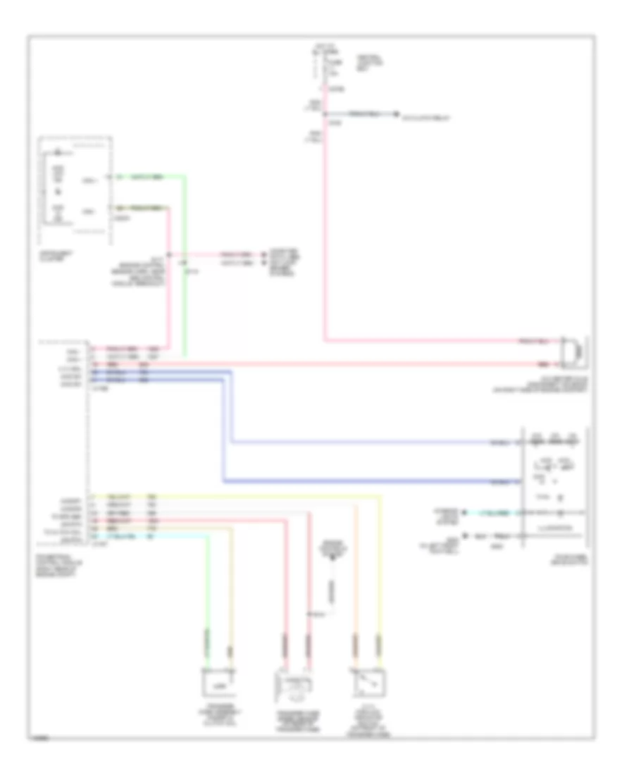
4WD Wiring Diagram, Mechanical for Ford Pickup F150 2004
List of elements for 4WD Wiring Diagram, Mechanical for Ford Pickup F150 2004:
- (engine control
- 2wd hi
- 4 x 4 high/low indicator switch (on front of transfer case)
- 4 x 4 sol
- 4wd hi
- 4wd hi ind
- 4wd lo
- 4wd low ind
- 4wd sw
- 4wdmp1
- 4wdmp2
- 4x4 center axle disconnect solenoid (on right side of engine compart)
- A/c clutch relay
- C175b
- C175t
- C220a
- C270b
- Can +
- Can -
- Central junction box
- Computer data lines, anti-lock brakes systems
- Engine controls system
- Four-wheel drive switch
- Fuse 10a
- G202 (in left front footwell)
- Hot at all times
- Illumination
- Instrument cluster
- Interior lights system
- Ohms
- Powertrain control module (right rear of engine compt)
- Red
- S105
- S117
- S118
- S141
- S283
- Sensor harn, near abs control module breakout)
- Sig rtn
- Tc cltch coil
- Tc spd sen
- Transfer case assembly magnetic clutch coil
- Transfer case speed sensor (on rear of transfer case)
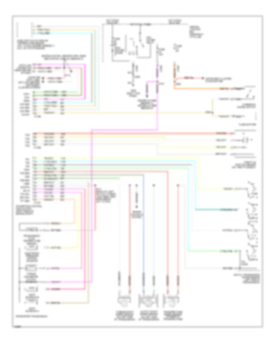
A/T Wiring Diagram for Ford Pickup F150 2004
List of elements for A/T Wiring Diagram for Ford Pickup F150 2004:
- (engine control sensor harn, near
- (near center of dash)
- 4r70e/4r75e transmission
- Abs control module breakout)
- C175b
- C175e
- C175t
- C270f
- Can +
- Can -
- Central junction box (near right "a" pillar)
- Computer data lines, anti-lock brakes, instrument cluster systems
- Data link connector
- Digital transmission range sensor (left side of transmission)
- Electronic pressure control solenoid
- Engine controls system
- Epc sol
- Feps
- Floor shifter
- Fuse 15a
- Fuse 5a
- G206 (right kick panel)
- Heated oxygen sensor 12, heated oxygen sensor 22
- Hot at all times
- Hot in run or start
- Instrument cluster, floor shifter
- Maf sen
- Mass air flow/intake air temperature sensor (4.6l: in air cleaner assembly) (5.4l: on top of engine)
- Nca
- O/d sw
- Ohms
- Oss
- Output shaft speed sensor (on left side of transmission)
- Overdrive cancel switch
- Pcm power diode
- Pcm power relay
- Powertrain control module (pcm) (right rear of engine compt)
- R p
- S117
- S118
- S141 (back-up light switch to rear lamp feed harn, near break- out to pcm)
- S225
- S284
- S355
- Shift solenoid a
- Shift solenoid b
- Sig rtn
- Sol b
- Tcc sol
- Tcs sen
- Tft sen
- Throttle position sensor (on throttle body)
- Torque converter clutch solenoid
- Tps
- Tr1
- Tr2
- Tr3a
- Tr4
- Transfer case speed sensor (on rear of transfer case)
- Transmission fluid temperature sensor
- Tss sen
- Turbine shaft speed sensor (on left side of transmission)
- Vref