TRANSMISSION
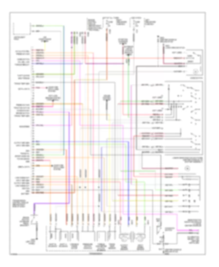
A/T Wiring Diagram for Jaguar XJR 1997
List of elements for A/T Wiring Diagram for Jaguar XJR 1997:
- (center console ground stud) g302
- (not used)
- A/c clutch rel
- Air conditioning system
- Anti-lock brakes system (trac signal)
- Battery
- Brake switch
- Brake switch (on brake pedal bracket)
- Ca1
- Ca36
- Cal sel link
- Calibration select link (dealer installed)
- Computer data lines system
- Cruise control system
- Data link in
- Eng speed
- Eng torque
- Engine control module (behind right side footwell trim panel)
- Exterior lights system (back-up lamps)
- Fuse 10a
- Fuse 5a
- G200 (left kick panel)
- G302 (center console ground stud)
- G401 (logic ground stud)
- Gb12
- Gb13
- Gb14
- Gear position indicator module ("j" gate, center console)
- Grd
- Hot at all times
- Hot in run
- Ignition
- Input spd sen
- Input speed sensor
- Instrument pack
- Kickdown sw
- Kickdown switch
- Left heelboard fuse box
- Linear gear position switches (center console, on shifter assembly)
- Mode switch
- Nca
- Norm
- Output spd sen
- Output speed sensor
- Pi104
- Pi105
- Pnk
- Press sw man
- Pressure switch manifold
- Red
- Right heelboard fuse box
- Serial data
- Shift a solenoid
- Shift b solenoid
- Sport
- Sport mode ind
- Ssa
- Ssb
- Starting/ charging system
- Tcc solenoid
- Thottle pos
- Torque converter clutch solenoid
- Torque reduct
- Traction active
- Trans mil
- Trans temp sen
- Trans temp sensor
- Transmission
- Transmission control module (behind right side of dash)
- Vari force mot
- Variable force motor
 English