TRANSMISSION
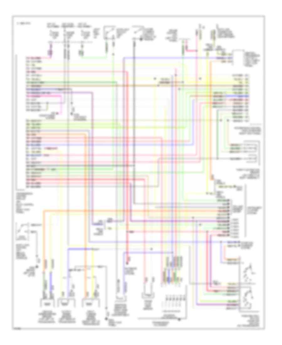
Transmission Wiring Diagram for Mazda RX-7 1994
List of elements for Transmission Wiring Diagram for Mazda RX-7 1994:
- (or)
- 1994 & models
- 1995 vftc c
- Air conditioning system
- Central processing unit no. 2 (anti-theft) (left kick panel)
- Cpu and speedo- meter
- Cruise control unit (left kick panel)
- D indic
- Data link connector (left engine compartment)
- Dropping resistor (right side of engine compartment)
- Ec-at control unit (right kick panel)
- Exterior lights system
- Fat
- G202 behind left side of i/p)
- G203 (right kick panel)
- Hold indic
- Hold switch
- Hot at all times
- Hot in on or start
- I/p)
- Ig-
- Input/ turbine speed sensor (front left of transmission)
- Instrument cluster system
- Joint box (left
- L indic
- Meter fuse 15a
- Models
- N indic
- N0. 1
- N0. 2
- N0. 3
- N0. 4
- N0. 5
- N0. 6
- Nca
- Output speed sensor (left rear of
- P indic
- Park/neutral switch (inhibitor switch) (on transmission)
- Pnk
- Powertrain control module (engine) (right kick panel)
- R indic
- Red
- Room fuse 10a
- S indic
- Shift-lock control unit (below center console)
- Solenoid valve (ec-at)
- Starting/ charging system
- Stop fuse 20a
- Stoplight switch (left i/p)
- Throttle position sensor (on throttle body assembly)
- Trans fluid temp sensor
- Transmission control module
- Transmission valve body
- Transmission)
- Vehicle speedometer sensor (top left of
- Water thermo- switch (front of engine)
 English