TRANSMISSION
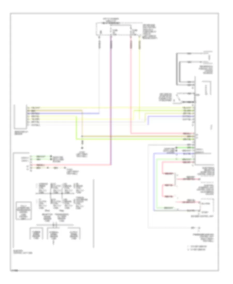
Transmission Wiring Diagram for Mercedes-Benz CLS550 2010
List of elements for Transmission Wiring Diagram for Mercedes-Benz CLS550 2010:
- 58d
- B1 brake ctrl sol vlv (vgs)
- B2 brake ctrl sol vlv (vgs)
- B3 brake ctrl sol vlv (vgs)
- Can-c h
- Can-c l
- Computer data lines system
- Driver side sam control module w/ fuse & relay module (left side of i7 engine compt)
- Eis (ezs) control unit
- Electric control unit (vgs)
- Electric steering lock control module (on steering column)
- Electronic selector lever module control module
- Elv-mas
- Fully integrated transmission control (vgs) control unit
- Fuse 7.5a
- Gear display sensor
- Gnd
- Hot w/ chassis circuit 87 relay energized
- Internal speed sensor (vgs)
- K1 clutch ctrl sol vlv (vgs)
- K2 clutch ctrl sol vlv (vgs)
- K3 clutch ctrl sol vlv (vgs)
- Keyless go start/stop pushbutton (if equipped)
- Nca
- Output speed sensor (vgs)
- P r n d- d+
- Passenger side sam control unit (right front footwell)
- Reversing & parking lock locking solenoid
- Selection range sensor (vgs)
- Start
- Torque converter lockup ctrl sol vlv (vgs)
- Transmission oil temp sensor (vgs)
- Turbine speed sensor (vgs)
- W/ keyless go
- W/o keyless go
- W15/2 (left front footwell)
- Working press ctrl sol vlv (vgs)
 English