TRANSMISSION
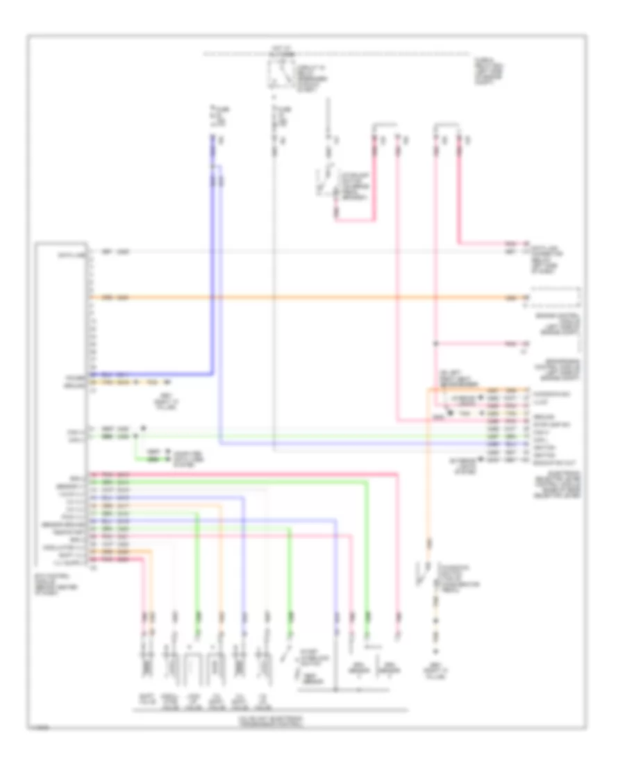
4WD Wiring Diagram for Mercedes-Benz ML320 2000

List of elements for 4WD Wiring Diagram for Mercedes-Benz ML320 2000:
- (on left front seat crossmember) g300
- (right "a" pillar) g901
- A11
- B10
- Battery
- Can h
- Can l
- Computer data lines system
- Double combination switch
- Fuse & relay box (left side of engine compt)
- Fuse 15a
- Fuse 25a
- Fuse 7.5a
- Ground
- High/low
- Hot at all times
- Hot in run or start
- Ignition
- Illum
- Instrument cluster
- Interior lights system
- Low range
- Low range ind
- Low range switch
- Low/high
- Nca
- P/c
- P/d
- Pnk
- Position 1
- Position 2
- Position 3
- Position 4
- Red
- Return
- Right front footwell fuse & relay box (behind right kick panel)
- Tan
- Transfer case control module (behind shift assembly)
- Transfer case range selection motor (left rear of transfer case)
A/T Wiring Diagram for Mercedes-Benz ML320 2000
List of elements for A/T Wiring Diagram for Mercedes-Benz ML320 2000:
- (on left front seat crossmember)
- 1-2/ 4-5 valve
- 1-2/4-5 vlv
- 2-3 shift valve
- 2-3 vlv
- 3-4 shift valve
- 3-4 vlv
- Backup sw out
- C/b
- C/d
- C/f
- Can (+)
- Can (-)
- Can h
- Can l
- Circuit 15 relay (energized in run & start)
- Computer data lines system
- Data line
- Data link connector (below left side of dash)
- Electronic selector lever control module (base of gear selector lever)
- Engine control module (left side of engine compt)
- Eps/sps/bas control module (left side of engine compt)
- Etc control module (behind center of dash)
- Exterior lights system
- Fuse & relay box (left side of engine compt)
- Fuse 15a
- G300
- G901 (right "a" pillar)
- Ground
- Hot at all times
- Ignition
- Illum
- Interior lights
- Kickdown sw
- Kickdown switch (top of accelerator pedal)
- Lock up valve
- Modul- ator valve
- Modulator vlv
- P/c
- P/d
- Pnk
- Power
- Pwm vlv
- Rpm 2
- Rpm 3
- Rpm sensor
- Sensor ground
- Sensor v+
- Shift valve
- Shift vlv
- Start interlock switch
- Stoplamp sw
- Stoplamp switch (on brake pedal bracket)
- Tan
- Temp sensor
- Temp/start
- Valve unit (electronic transmission control)