TRANSMISSION
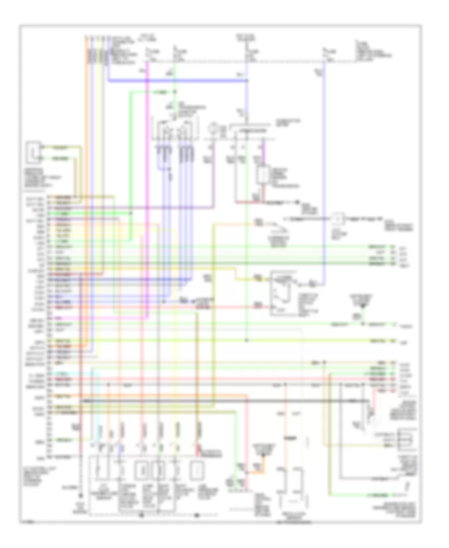
A/T Wiring Diagram for Nissan Quest XE 1997
List of elements for A/T Wiring Diagram for Nissan Quest XE 1997:
- (on transmission) inhibitor switch
- 1 sw
- 2 sw
- A/t control unit (behind dash, right of steering column)
- A/t fluid temperature sensor
- All times
- Ascd
- Ascd control unit (behind center of dash)
- Atck
- Automatic transaxle red
- Avcc
- Closed throttle
- Clsd sw
- Combination meter
- D sw
- Data clk
- Data in
- Data link connector (for consult) (behind dash, next to fuse block)
- Data out
- Dropping resistor (lower left front corner of engine compt)
- Dt1
- Dt2
- Dt3
- Duty sol
- Eng rev
- Engine control module (ecm) (behind right side of dash)
- Engine coolant temperature sensor (top right side of engine)
- Exterior lights system
- Fl temp
- Fuse 10a
- Fuse block (behind dash, left of steering column)
- G105 (rear of right front fender)
- G133 (on engine)
- G206 (center of dash)
- Gnd
- Gnd-a
- Hot at
- Hot in on or start
- Instrument cluster system
- J/c 2 (in fuse box)
- Line pressure solenoid valve
- Mem b/u
- N sw
- Nca
- Neut
- O/d off ind.
- Obd2
- Od ind
- Od sw
- Over- run clutch sole- noid valve
- Overdrive control switch
- Ovr/c
- R sw
- Red
- Revolution sensor (on transmission)
- Sens gnd
- Sens pwr
- Shift sole- noid valve "a"
- Shift solenoid valve "b"
- Speedometer
- Ssa
- Ssb
- Tacho
- Th/sens
- Throttle position sensor (on throttle body)
- Throttle position switch (on throttle body)
- Torque con- verter clutch solenoid valve
- Tvo
- Tvo1
- Vehicle speed sensor (on transmission)
- Vign
- Vsp
- Vsp-1
- Vsp-2
- W/tmp
- Wo sw
- Wot
 English