TRANSMISSION
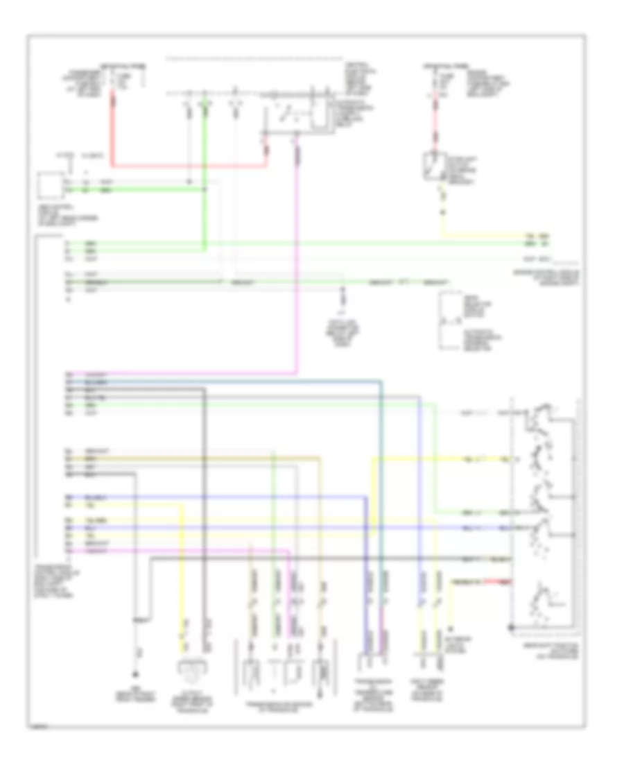
A/T Wiring Diagram, 4T65EV for Volvo V70 XC 2001

List of elements for A/T Wiring Diagram, 4T65EV for Volvo V70 XC 2001:
- Abs control module (at left rear corner of eng compt)
- Automatic transmission program selector
- B13
- B26
- C24
- Central electrical module (behind left side of dash)
- Data link connector (below left side of dash)
- Engine compartment fuse/relay box (left side of eng compt)
- Engine control module (right side engine compt)
- Fuse b12 5a
- Fuse c21 10a
- G93 (rear of left front fender)
- G94 (rear of right front fender)
- Gear selector module switch
- Gear shift position switches (on top of transaxle)
- Hot at all times
- Input speed sensor (on transaxle)
- Nca
- Nca ot
- Nca otg
- Nca sp2+
- Nca sp2-
- Oil pressure sensor (on rear of transaxle)
- Output speed sensor (on transaxle)
- Passenger compartment fuse box (at left end of dash)
- Red
- Sth
- Sthg
- Stoplight switch (on brake pedal bracket)
- Transmission control module (right side of eng compt, fwd of strut tower)
- Transmission oil temperature sensor (on transaxle)
- Transmission solenoids (in transaxle)
- W/ dstc
- W/ stc
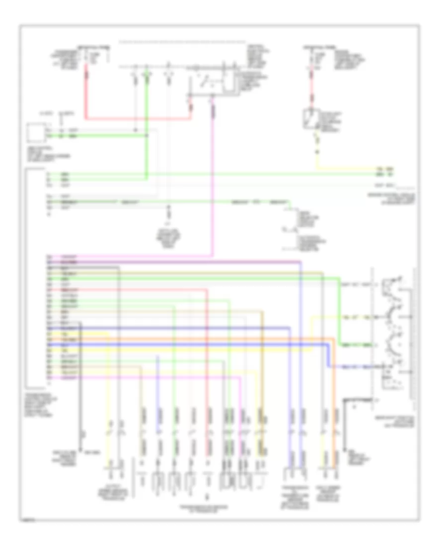
A/T Wiring Diagram, AW50-42 for Volvo V70 XC 2001
List of elements for A/T Wiring Diagram, AW50-42 for Volvo V70 XC 2001:
- Abs control module (at left rear corner of eng compt)
- Automatic transmission program selector
- B13
- B26
- C24
- Central electrical module (behind left side of dash)
- Data link connector (below left side of dash)
- Engine compartment fuse/relay box (left side of eng compt)
- Engine control module (at right side of engine compt)
- Exterior lights system
- Fuse b12 5a
- Fuse c21 10a
- G96 (rear of right front fender)
- Gear selector module switch
- Gear shift position switches (on transaxle)
- Hot at all times
- Input speed sensor (on rear of transaxle)
- Output speed sensor (right front of transaxle)
- Passenger compartment fuse box (at left end of dash)
- Red
- Sth
- Sthg
- Stoplight switch (on brake pedal bracket)
- Transmission control module (right side of eng compt, forward of strut tower)
- Transmission oil temperature sensor (bottom rear of transaxle)
- Transmission solenoids (in transaxle)
- W/ dstc
- W/ stc
A/T Wiring Diagram, AW55-50 for Volvo V70 XC 2001
List of elements for A/T Wiring Diagram, AW55-50 for Volvo V70 XC 2001:
- (s80/v70) g96 (rear of right front fender)
- Abs control module (at left rear corner of eng compt)
- Automatic transmission program selector
- B13
- B26
- C24
- Central electrical module (behind left side of dash)
- Data link connector (below left side of dash)
- Engine compartment fuse/relay box (left side of eng compt)
- Engine control module (at right side of engine compt)
- Fuse b12 5a
- Fuse c21 10a
- G93 (rear of left front fender)
- G94 (s60)
- Gear selector module switch
- Gear shift position switches (on transaxle)
- Hot at all times
- Input speed sensor (on rear of transaxle)
- Nca
- Output speed sensor (right front of transaxle)
- Passenger compartment fuse box (at left end of dash)
- Red
- Sls
- Slsg
- Slt
- Sltg
- Slu
- Slug
- Stoplight switch (on brake pedal bracket)
- Transmission control module (right side of eng compt, forward of strut tower)
- Transmission oil temperature sensor (bottom rear of transaxle)
- Transmission solenoids (in transaxle)
- W/ dstc
- W/ stc