WARNING SYSTEMS
Chime Wiring Diagram for Hyundai Elantra Touring GLS 2010

List of elements for Chime Wiring Diagram for Hyundai Elantra Touring GLS 2010:
- Bcm (behind center of dash)
- Chime buzzer
- Cluster fuse 10a
- Driver door switch (on left "b" pillar)
- Driver seat belt switch (under driver front seat)
- Drv dr sw
- Gf31 (lower left "b" pillar)
- Gm21 (behind left side of dash)
- Head
- Hot at all times
- Hot in on or start
- I/p-c
- Ignition key illumination & door warning switch (right side of steering column)
- Ill
- Instrument cluster
- J/c jm02 (lower left side of dash)
- J/c jm04 (lower left side of dash)
- Key hole ill
- Key in sw
- Light switch
- M01-a
- M01-b
- M02-l
- M04-a
- M04-b
- M04-c
- Multi-function switch
- Nca
- Off
- Park
- Passenger compartment junction block (under left side of dash, near kick panel)
- Power connector
- Red
- Room lp fuse 15a
- Seat belt ind
- Seat belt sw
- Tail lmp sw in
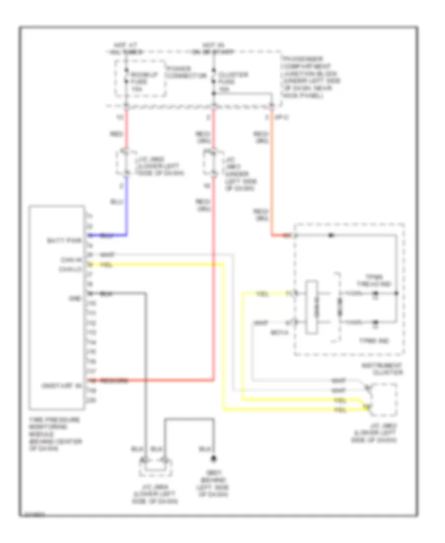
Tire Pressure Monitoring Wiring Diagram for Hyundai Elantra Touring GLS 2010
List of elements for Tire Pressure Monitoring Wiring Diagram for Hyundai Elantra Touring GLS 2010:
- Batt pwr
- Can hi
- Can ic
- Can lo
- Cluster fuse 10a
- Gm21 (behind left side of dash)
- Gnd
- Hot at all times
- Hot in on or start
- I/p-c
- Instrument cluster
- J/c jm02 (lower left side of dash)
- J/c jm03 (under left side of dash)
- J/c jm04 (lower left side of dash)
- Micom
- Mo1-a
- On/start in
- Passenger compartment junction block (under left side of dash, near kick panel)
- Power connector
- Red
- Room lp fuse 15a
- Tire pressure monitoring module (behind center of dash)
- Tpms ind
- Tpms tread ind