WARNING SYSTEMS
Chime Wiring Diagram for Hyundai Veloster 2012

List of elements for Chime Wiring Diagram for Hyundai Veloster 2012:
- "b" pillar)
- "c" pillar)
- (at right
- (top left side of dash)
- Auto
- B-can high
- B-can low
- B-can transceiver
- Cluster fuse 10a
- Computer data lines system
- Door open ind
- Driver door switch (on left "b" pillar)
- Driver seat belt buckle switch (depowered a/bag)
- Driver seat belt switch
- Drv dr sw
- Gf03 (at left "b" pillar)
- Gf04
- Gm01
- Gm01 (top left side of dash)
- Head
- Hot at all times
- Hot in on or start
- I/p-b
- I/p-c
- I/p-d
- I/p-g
- I/p-h
- Ignition key ill & door warning switch (w/o smart key)
- Instrument cluster
- Ips control module
- Leak current autocut device
- Light
- M01-l
- Mcu
- Memory fuse 10a
- Mf11
- Mf61
- Multifunction
- Nca
- Off
- Pass dr sw
- Passenger door switch (on right
- Pnk
- Rear dr sw
- Red
- Right rear door switch (at right
- Seat belt ind
- Side of dash)
- Smart junction box (behind left
- Sw key in door warning
- Switch
- Tail
- Tail lamp sw
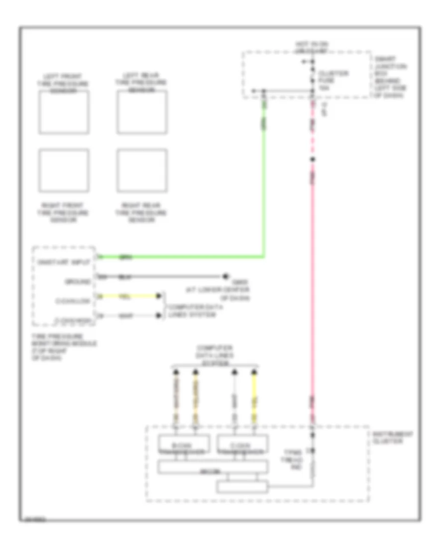
Tire Pressure Monitoring Wiring Diagram for Hyundai Veloster 2012
List of elements for Tire Pressure Monitoring Wiring Diagram for Hyundai Veloster 2012:
- (at lower center
- B-can transceiver
- C-can high
- C-can low
- C-can transceiver
- Cluster fuse 10a
- Computer data lines system
- Gm05
- Ground
- Hot in on or start
- I/p-g
- Ind
- Instrument cluster
- Left front tire pressure sensor
- Left rear tire pressure sensor
- Micom
- Of dash)
- On/start input
- Pnk
- Right front tire pressure sensor
- Right rear tire pressure sensor
- Smart junction box (behind left side of dash)
- Tire pressure monitoring module (top right of dash)
- Tpms tread