WARNING SYSTEMS
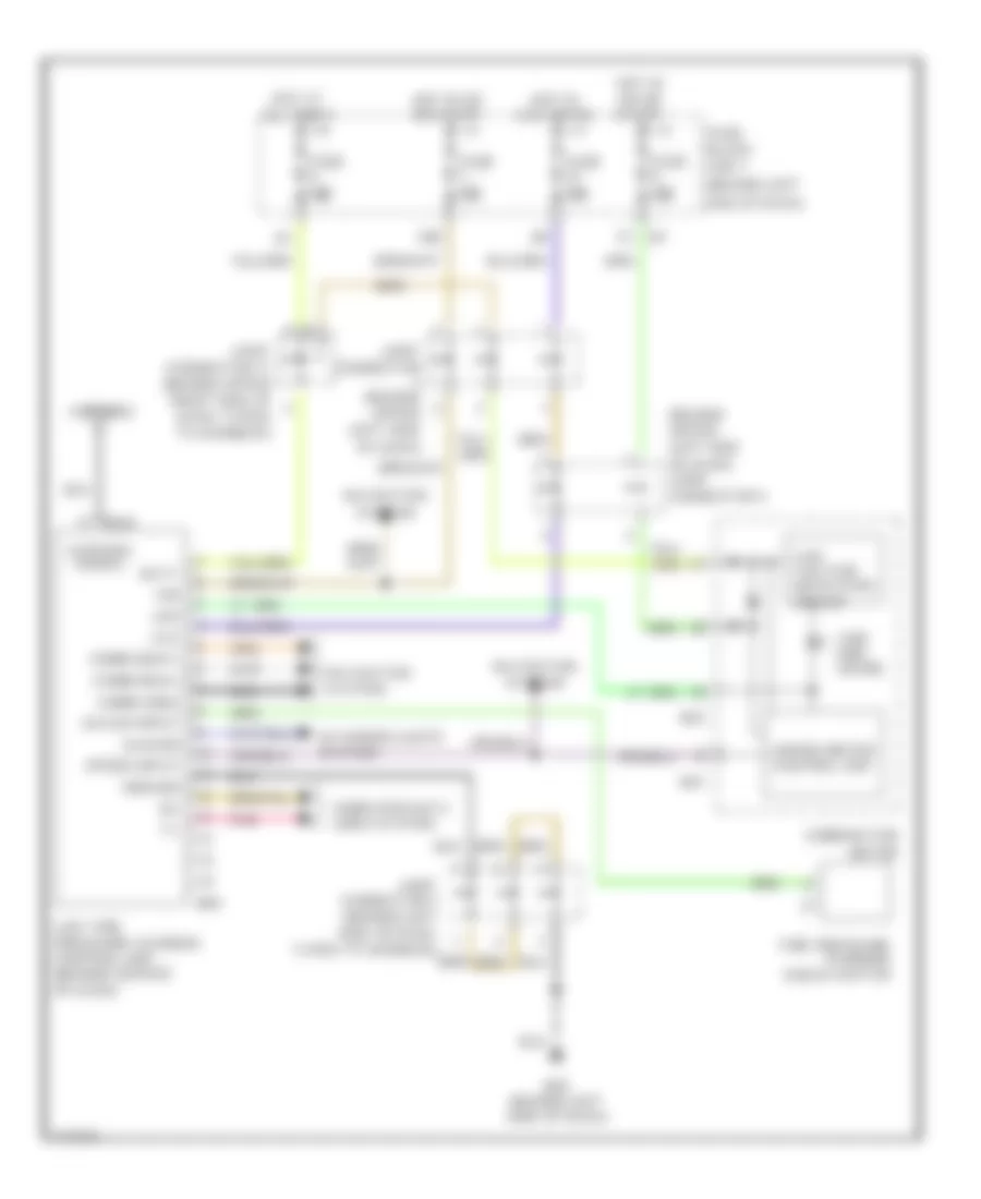
Chime Wiring Diagram for Infiniti Q45 2004

List of elements for Chime Wiring Diagram for Infiniti Q45 2004:
- (behind dash, left of steering column)
- (behind left side of dash) m24
- 15a
- 1st
- 20b
- 2nd
- 7c m1
- Auto
- B17 (under left front door sill)
- Bat
- Belt ind
- Body control module (behind left kick panel)
- Chime
- Combination meter
- Combination switch (lighting switch)
- Diode
- Door ind
- Door sw (dr)
- Dr warn lamp
- Exterior lights system
- Front door switch (driver side)
- Front power seat (driver side)
- Fuse 1 10a
- Fuse 10a
- Fuse 3 10a
- Fuse 6 10a
- Fuse block (j/b) 1 (behind left end of dash)
- Fuse block (j/b) 2 (behind right kick panel)
- Gnd
- Headlamp battery saver control unit
- Hot at all times
- Hot in on or start
- Ign sw
- Ignition
- Joint connector (behind center of dash)
- Joint connector (behind upper left side of dash)
- Joint connector (behind upper right end of dash, taped to harness)
- Joint connector (behind upper right side of dash, taped to harness)
- Joint connector 18 (behind upper right end of dash, taped to harness)
- Joint connector 20 (behind right side of dash, taped to harness)
- Key sw
- Key switch & key lock solenoid
- Lt sw (1st)
- M115 (behind right side of dash)
- M145
- M33
- M34
- M43
- Off
- Seat belt buckle switch
- Seat blt sw
- T/l sw1
- T/l sw2
- Tail/l rly
- Unified meter control unit
- Warning chime
Tire Pressure Monitoring Wiring Diagram for Infiniti Q45 2004
List of elements for Tire Pressure Monitoring Wiring Diagram for Infiniti Q45 2004:
- (behind left
- (behind upper left side of dash) joint connector 4
- 19b
- Acc
- Antenna
- Antenna signal
- Batt
- Combination
- Commi (bus+)
- Commi (bus-)
- Commi (gnd)
- Computer data lines system
- Diag-id input
- End of dash)
- Exterior lights system
- Fuse 10a
- Fuse block (j/b) 1
- Ground
- Hazard
- Hot at all times
- Hot in acc or on
- Hot in on or start
- Ign
- Joint connector (behind upper left side of dash)
- Joint connector 11 (behind upper right side of dash, taped to harness)
- Joint connector 5 (behind left side of dash, taped to harness)
- Led
- Low tire pressure warning control unit (behind center of dash)
- Low voltage detection circuit
- M25 (behind left side of dash)
- M41
- M424
- M43
- M84
- Meter
- Navigation system
- Nca
- Pnk
- Speed input
- Tire pre- ssure
- Tire pressure warning check switch
- Unfied meter control unit