WARNING SYSTEMS
Chime Wiring Diagram for Mitsubishi Mirage ES 2014

List of elements for Chime Wiring Diagram for Mitsubishi Mirage ES 2014:
- Brake fluid level switch
- Brake ind
- C-123
- C-124
- C-212
- C-28
- C-29
- C-32
- C-403
- C-404
- C-416
- Can
- Can drive circuit
- Can+
- Can-
- Circuit drive led
- Circuit transceiver
- Column ecu
- Column switch (on steering column)
- Combination meter
- Computer data lines system
- Cpu
- Ddsw
- Driver's seat belt ind
- Driver's side seat belt switch (in driver's seat belt buckle)
- Etacs-ecu
- Fuse 15a
- Fuse 7.5a
- G11 (right side of engine compt)
- G20 (under driver seat)
- G3 (right kick panel)
- G4 (under right rear of engine)
- Head
- Hl1+
- Hot at all times
- Hot in on or start
- Interface circuit
- J/c 10 (c-10) (left side of dash)
- J/c 7 (c-105)
- J/c 9 (c-109)
- Junction block (left end of dash)
- Key reminder switch
- Left front door switch (left front "b" pillar)
- Lighting switch
- Lin interface
- Nca
- Parking brake switch
- Passenger's air bag off indicator light assembly
- Passenger's seat belt switch (in passenger's seat belt buckle)
- Pbs-
- Pbso
- Pnk
- Red
- Relay box (left rear corner of engine compt)
- Srs-ecu (under front of center console)
- Tail
- Tone alarm
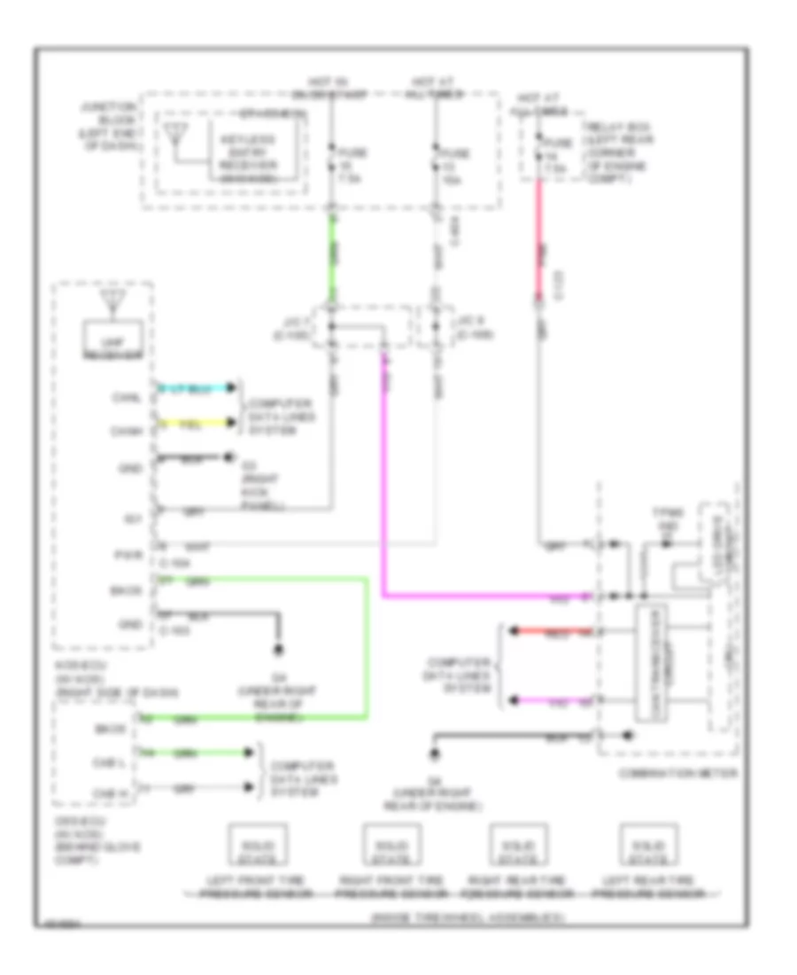
Tire Pressure Monitoring Wiring Diagram for Mitsubishi Mirage ES 2014
List of elements for Tire Pressure Monitoring Wiring Diagram for Mitsubishi Mirage ES 2014:
- (c-109)
- (inside tire/wheel assemblies)
- (w/ kos) (right side of dash)
- Bkos
- C-103
- C-104
- C-123
- C-404
- Cab h
- Cab l
- Can transceiver
- Canh
- Canl
- Circuit
- Combination meter
- Computer data lines system
- Cpu
- Etacs-ecu
- Fuse 15a
- Fuse 7.5a
- G3 (right kick panel)
- G4 (under right rear of engine)
- Gnd
- Hot at all times
- Hot in on or start
- Ig1
- J/c 7 (c-105)
- J/c 9
- Junction block (left end of dash)
- Keyless entry receiver (w/o kos)
- Kos-ecu
- Led drive circuit
- Left front tire pressure sensor
- Left rear tire pressure sensor
- Oss-ecu (w/ kos) (behind glove compt)
- Pnk
- Pwr
- Red
- Relay box (left rear corner of engine compt)
- Right front tire pressure sensor
- Right rear tire pressure sensor
- Solid state
- Tpms ind
- Uhf receiver