WIPER/WASHER
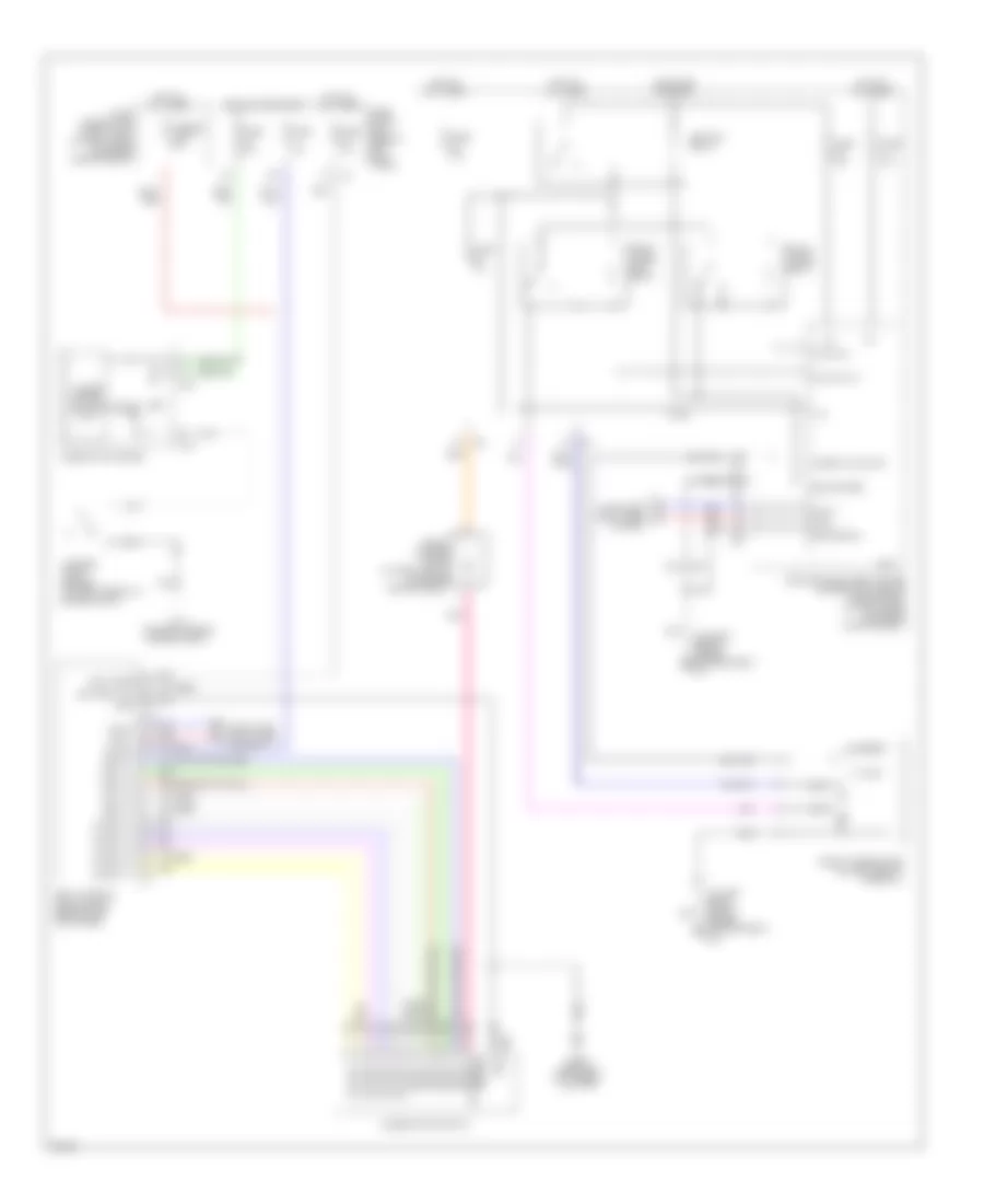
Wiper/Washer Wiring Diagram for Infiniti G35 2004
List of elements for Wiper/Washer Wiring Diagram for Infiniti G35 2004:
- (on left front side of engine compartment) e43
- (on right side of engine compartment) e17
- +ig
- 15a
- Bat (fuse)
- Battery (f/l)
- Body control module (bcm) (behind left kick panel)
- Can-h
- Can-l
- Combination meter
- Combination switch
- Computer data lines system
- Cpu
- E17 (on right side of engine compt)
- F/wip hi rly
- F/wip rly
- Front washer motor (at right front of engine compartment)
- Front wiper high relay
- Front wiper motor (on left side of firewall)
- Front wiper relay
- Fuse 10a
- Fuse 15a
- Fuse 20a
- Fuse block (j/b) (behind left kick panel)
- Fuse, fusible link & relay box (at right rear of engine compartment)
- Fusible link f 50a
- Gnd
- Gnd (power)
- Gnd (signal)
- High
- Hot at all times
- Hot in on or start
- Ign sw
- Ignition relay
- Input 1
- Input 2
- Input 3
- Input 4
- Input 5
- Ipdm e/r (intelligent power distribution module engine room) (at right rear of engine compartment)
- Low
- M19
- M20
- M29
- M30 (behind instrument cluster)
- Motor fr washer
- Move
- Output 1
- Output 2
- Output 3
- Output 4
- Output 5
- Pnk
- Red
- Stop
- Unified meter control unit
- Washer ind
- Washer level sensor (at right front of engine compt)
- Wiper auto stop
 English