AIR CONDITIONING
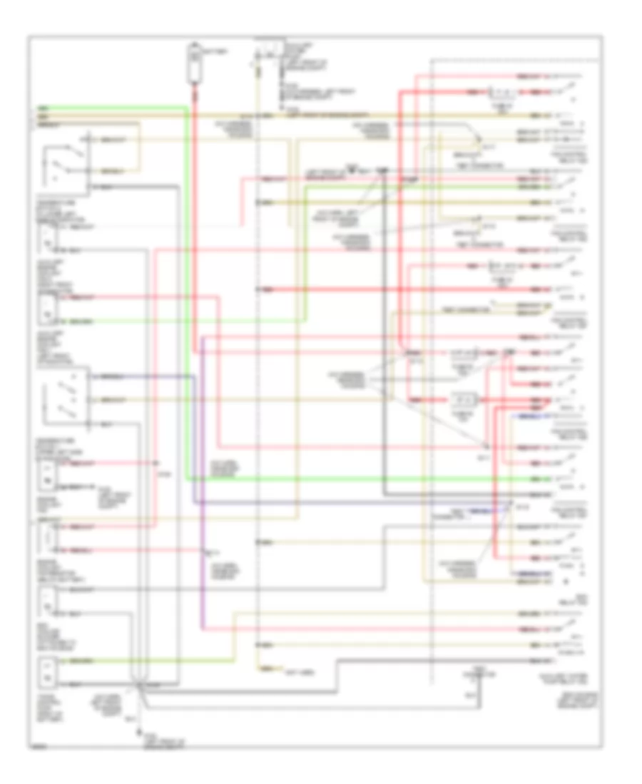
Air Conditioning Wiring Diagrams (1 of 2) for Cadillac Catera 1997
 https://portal-diagnostov.com/license.html
Automotive Electricians Portal FZCO
Automotive Electricians Portal FZCO
https://portal-diagnostov.com/license.html
https://portal-diagnostov.com/license.html
Automotive Electricians Portal FZCO
Automotive Electricians Portal FZCO
List of elements for Air Conditioning Wiring Diagrams (1 of 2) for Cadillac Catera 1997:
- (a/c harn, in ecm housing)
- (a/c harn, left front of engine compt)
- (i/p harn, near break- out to dlc)
- (i/p harn, right side of i/p)
- (i/p harness, near cluster breakout)
- (i/p harness, near dlc breakout)
- (left front of engine compt)
- (left front of engine compt) g100
- (left side of i/p) data link connector
- +5v
- A/c compressor clutch coil
- A/c compressor diode
- A/c compressor refrigerant pressure switch (left front of engine compt)
- A/c compressor relay
- A/c control switch (left front of engine compt)
- A/c cutout
- A/c req
- A/c req out
- A/c request
- A11
- A400
- Air mix 1
- Air mix 2
- Air mix 3
- Air mix 4
- Ambient air outside temperature sensor
- Blower diag
- Blower motor (right side of i/p)
- Blower out
- Body control module (on right "a" pillar)
- Bp900
- Cig fuse 14 20a
- Clamp 15a fuse 10 10a
- Clamp 56 fuse 26 10a
- Comp inhibit
- Day/night sig
- Def 1
- Def 2
- Def 3
- Def 4
- Defog sw
- Defogger system
- Defroster valve actuator (right side of i/p)
- Diagnostic out
- Ecm housing (left front of engine compt)
- Electronic brake/ traction control module (left front of engine compt)
- Engine control module
- F800
- F830
- Floor 1
- Floor 2
- Floor 3
- Floor 4
- Fm11
- Fm14
- Fm430
- Fm60
- Fm8
- Fp120
- Fp812
- Fuse block
- G100
- Ground
- Headlamp automatic control ambient light sensor (top of i/p)
- Headlights system
- Heater and a/c control
- Heater and a/c recirc vacuum solenoid valve (behind right side of i/p)
- Heater and a/c water vacuum solenoid valve (behind right side of i/p)
- Heater blower fuse 33 30a
- Hot at all times
- Hot in run
- Hot in run, bulb test or start
- Hzd fuse 12 20a
- Ign volt
- Inside air valve actuator (right side of i/p)
- Int dim
- Interior lights system
- Left air duct temperature sensor (behind right side of i/p)
- Left temperature valve actuator (right side of i/p)
- Mode valve actuator (right side of i/p)
- O/s mirror fuse 13 10a
- Outside temp
- P11
- P111
- Pa400
- Pa900
- Pm4
- Power
- Rb400
- Recirc valve
- Red
- Relay ctrl
- Right air duct temperature sensor (behind right side of i/p)
- Right temperature valve actuator (right side of i/p)
- Ru502
- S110
- S160
- S205
- S211
- S215
- S220
- S229
- Sens gnd
- Sens left
- Sens right
- Serial data
- Speed input
- Speed sig
- Sun sens
- Test connector (in ecm housing)
- Trans- mission controls system
- Twilight sens
- Vent 1
- Vent 2
- Vent 3
- Vent 4
- Water vlv
- X800
- X812
- X839
- Xm110
- Xm112
- Xp33
- Xy360
Air Conditioning Wiring Diagrams (2 of 2) for Cadillac Catera 1997
 https://portal-diagnostov.com/license.html
Automotive Electricians Portal FZCO
Automotive Electricians Portal FZCO
https://portal-diagnostov.com/license.html
https://portal-diagnostov.com/license.html
Automotive Electricians Portal FZCO
Automotive Electricians Portal FZCOList of elements for Air Conditioning Wiring Diagrams (2 of 2) for Cadillac Catera 1997:
- (a/c harn, inside ecm housing)
- (a/c harn, left front of engine compt)
- (a/c harness, inside ecm housing)
- (left front of engine compt)
- (not used)
- Auxiliary engine coolant fan 1 (left front of radiator)
- Auxiliary engine coolant fan 2 (right front of radiator)
- Auxiliary water pump (left front of engine compt)
- Auxiliary water pump relay k22
- Battery
- Ecm cooling blower (attached to ecm housing)
- Ecm housing (left front of engine compt)
- Ecm relay k48
- Engine coolant fan
- Engine coolant fan resistor (below battery)
- Fan control relay k26
- Fan control relay k28
- Fan control relay k52
- Fan control relay k67
- Fan control relay k87
- Fuse 40 30a
- Fuse 42 40a
- Fuse 50 10a
- Fuse 52 30a
- G100
- G100 (left front of engine compt)
- Of engine compt)
- Red
- S108
- S109
- S111
- S112
- S113
- S114
- S115
- S116
- S117
- S118
- S125
- Temperature switch 1 (upper left side of radiator)
- Temperature switch 2 (in lower left side of radiator)
- Test connector
- Timing control pump (right of battery)
- Y red

 Čeština
 Dansk
Dansk Deutsch
 Ελληνικά
 English
 English
 Español
 Suomi
Suomi Français
 Français
 עברית
עברית Hrvatski
 Magyar
 Italiano
 日本語
日本語 한국어
한국어 Nederlands
 Polski
 Português
 Português
 Română
 Русский
 Slovenčina
 Slovenščina
 Svenska
 Türkçe
