AUTOMOTIVE ELECTRICIANS PORTAL

STARTING/CHARGING – Honda Odyssey Touring 2013 – SYSTEM WIRING DIAGRAMS

STARTING/CHARGING

Charging Wiring Diagram for Honda Odyssey Touring 2013

Charging Wiring Diagram for Honda Odyssey Touring 2013 https://portal-diagnostov.com/license.html
https://portal-diagnostov.com/license.html Automotive Electricians Portal FZCO Automotive Electricians Portal FZCO
Download PDF file

List of elements for Charging Wiring Diagram for Honda Odyssey Touring 2013:

  • A10
  • A48
  • A49
  • Altc
  • Alternator
  • Altf
  • Altl
  • Battery
  • C101
  • C210
  • C212
  • C42
  • C43
  • C44
  • Can h
  • Can l
  • Center junction box (right side of dash)
  • Charging system indicator
  • Computer data lines system
  • Control circuits
  • Driver's under-dash fuse/relay box (left end of dash)
  • Eld
  • Eld unit
  • F-can transceiver
  • F21
  • Fuse 10a
  • Fuse 11 7.5a
  • Fuse 12 20a
  • Fuse 15a
  • Fuse 24 7.5a
  • G1 (left side of engine compt)
  • G302 (left side of dash)
  • G401 (left side of dash)
  • Gauge control module
  • Ground distribution system
  • Hot at all times
  • Hot in on or start
  • J/c c104 (top right side of engine)
  • Main fuse 125a
  • Main under-hood fuse box (left side of engine compt)
  • Multi- fuse 1
  • Nca
  • Pcm (right rear of engine compt)
  • Power distribution system
  • Red
  • T101
  • Tan
  • Under-hood fuse/relay box (right rear of engine compt)
  • W/o navigation & usb adapter

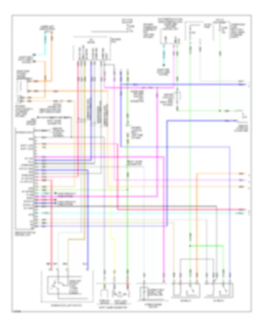
Remote Starting Wiring Diagram (1 of 2) for Honda Odyssey Touring 2013

Remote Starting Wiring Diagram (1 of 2) for Honda Odyssey Touring 2013 https://portal-diagnostov.com/license.html
https://portal-diagnostov.com/license.html Automotive Electricians Portal FZCO Automotive Electricians Portal FZCO
获取访问所有汽车的接线图Download PDF file

List of elements for Remote Starting Wiring Diagram (1 of 2) for Honda Odyssey Touring 2013:

  • (on steering column, near steering lock) immobilizer keyless control unit
  • (right rear of engine compt)
  • (right side of dash) center junction box
  • (under left side of dash) dlc
  • 40a
  • Antenna input
  • B-can hi
  • B-can lo
  • Center junction box (right side of dash)
  • Combi gnd
  • Combination light switch
  • Combination light switch connector
  • Computer data lines system
  • Driver's junction box 1 (left side of dash)
  • Driver's junction box 2 (w/ memory) (left side of dash)
  • Driver's micu
  • Driver's under-dash fuse/relay box (left end of dash)
  • F26
  • Fr wip int
  • Fuse 10a
  • Fuse 7.5a
  • G12
  • G403 (center of dash)
  • Gnd
  • H/l 0n sw
  • H/l off cut
  • H/l off sw
  • Headlight switch 0) off 1) park 2) auto 3) head
  • Hot at all times
  • Hot in on or start
  • Ig1
  • Ig1 meter
  • Ig1 relay
  • Ig1/ig2 fuse
  • Ig2
  • Ig2 relay
  • Immobilizer keyless control unit connector
  • Imocd
  • Int vr+
  • Intermittent dwell time controller
  • K-line
  • Option connector (remote starting) (left side of dash)
  • P13
  • P15
  • P17
  • P19
  • Park pin switch
  • Pnk
  • Red
  • Remote starting control unit
  • Remote starting in-line fuse
  • Remote starting system antenna
  • Rly-gnd
  • S-net
  • Scs
  • Shift lever connector
  • Shift lock
  • Shift lock solenoid
  • Small lt sw
  • Sts
  • Under-hood fuse/ relay box
  • Vbu
  • Vol+
  • Wip cut gnd
  • Wiper gnd
  • Wiper/washer switch
  • Wiper/washer switch connector

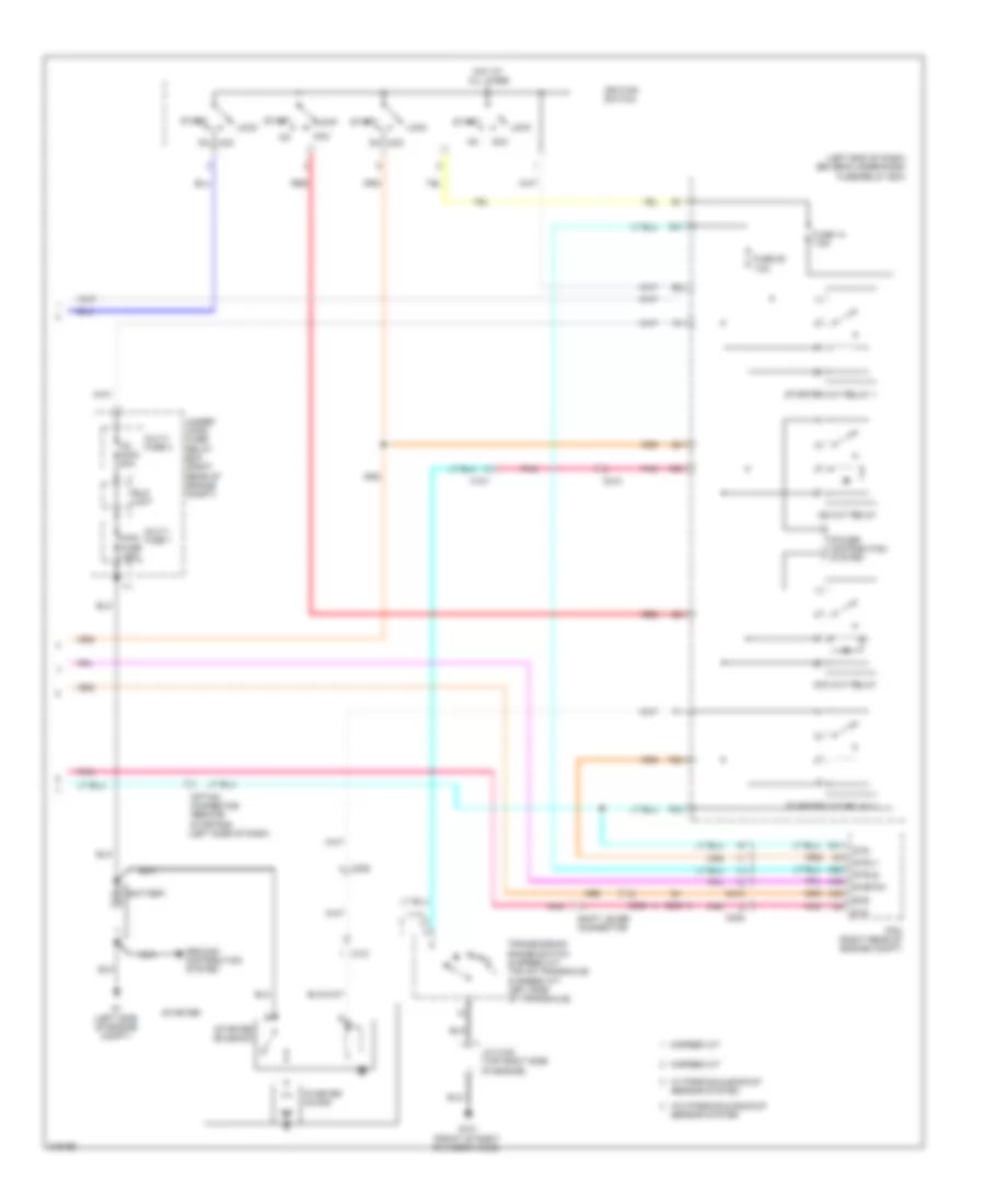
Remote Starting Wiring Diagram (2 of 2) for Honda Odyssey Touring 2013

Remote Starting Wiring Diagram (2 of 2) for Honda Odyssey Touring 2013 https://portal-diagnostov.com/license.html
https://portal-diagnostov.com/license.html Automotive Electricians Portal FZCO Automotive Electricians Portal FZCO
获取访问所有汽车的接线图Download PDF file

List of elements for Remote Starting Wiring Diagram (2 of 2) for Honda Odyssey Touring 2013:

  • (left end of dash) driver's under-dash fuse/relay box
  • 5-speed a/t
  • 6-speed a/t
  • A28
  • A31
  • A32
  • A46
  • Acc
  • Acc cut relay
  • Battery
  • C101
  • C205
  • C208
  • C210
  • Eld unit
  • F23
  • F27
  • F28
  • F29
  • Fuse 14 7.5a
  • Fuse 25 7.5a
  • G1 (left side of engine compt)
  • G101 (front of right cylinder head)
  • Ground distribution system
  • Hot at all times
  • Ig1 main 50a
  • Ig2 cut relay
  • Ignition switch
  • J/c c102 (top right side of engine)
  • Lock
  • Main fuse 125a
  • Multi- fuse 1
  • Multi- fuse 3
  • Nca
  • Option connector (remote starting) (left side of dash)
  • Pcm (right rear of engine compt)
  • Pnk
  • Power distribution system
  • Red
  • S-net5v
  • Scs
  • Sensor system
  • Shift lever connector
  • Sls
  • Start
  • Starter
  • Starter cut relay 1
  • Starter cut relay 2
  • Starter motor
  • Starter solenoid
  • Strld
  • Strly
  • Sts
  • Transmission range switch (6 speed a/t: top of transaxle) (5 speed a/t: left side of transaxle)
  • Under- hood fuse/ relay box (right rear of engine compt)
  • W/ parking & backup
  • W/o parking & backup

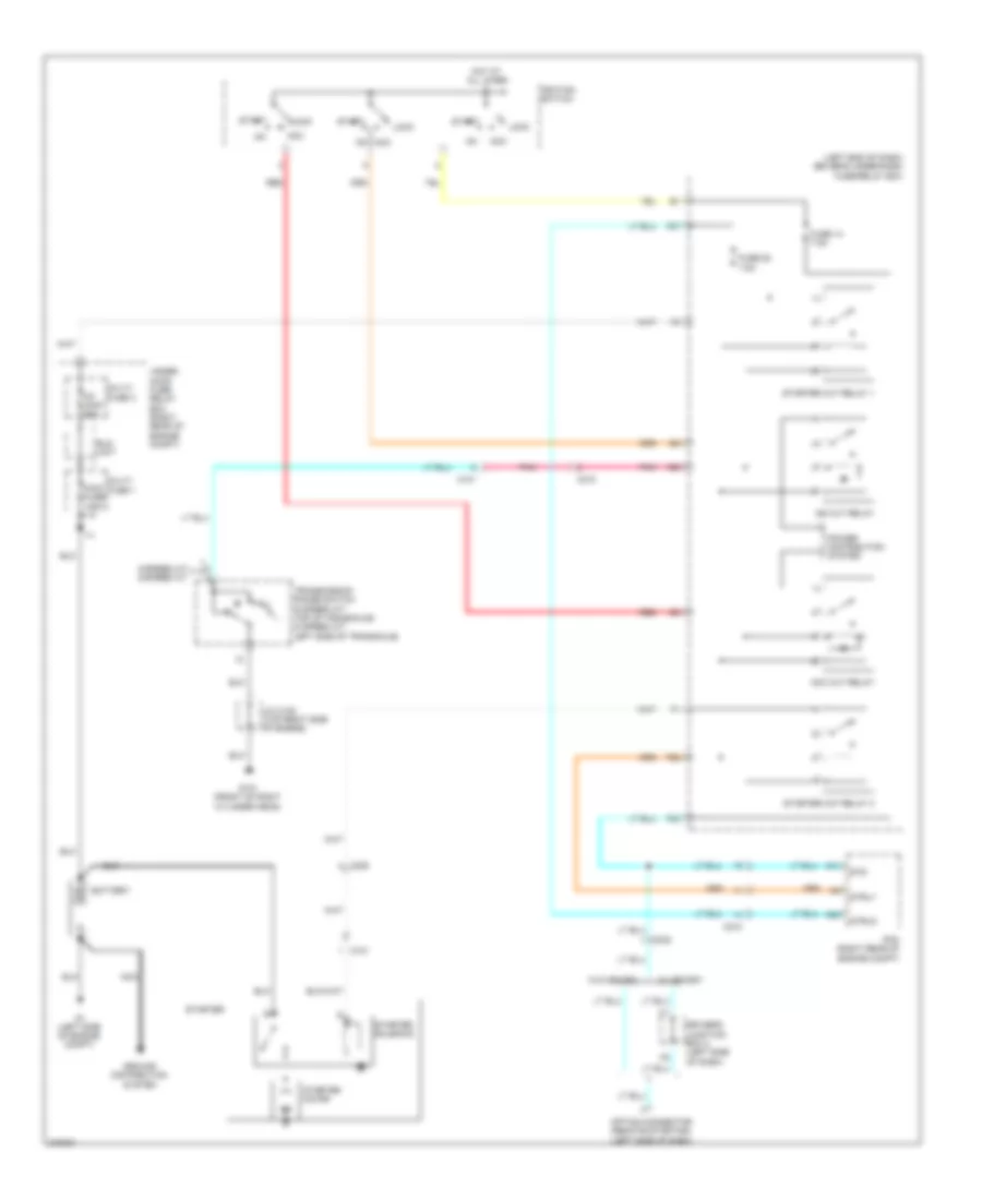
Starting Wiring Diagram for Honda Odyssey Touring 2013

Starting Wiring Diagram for Honda Odyssey Touring 2013 https://portal-diagnostov.com/license.html
https://portal-diagnostov.com/license.html Automotive Electricians Portal FZCO Automotive Electricians Portal FZCO
获取访问所有汽车的接线图Download PDF file

List of elements for Starting Wiring Diagram for Honda Odyssey Touring 2013:

  • (left end of dash) driver's under-dash fuse/relay box
  • 5-speed a/t 6-speed a/t
  • A28
  • A31
  • Acc
  • Acc cut relay
  • Battery
  • C101
  • C208
  • C210
  • C302
  • Driver's junction box 2 (left side of dash)
  • Eld unit
  • F23
  • F27
  • F28
  • F29
  • Fuse 14 7.5a
  • Fuse 25 7.5a
  • G1 (left side of engine compt)
  • G101 (front of right cylinder head)
  • Ground distribution system
  • Hot at all times
  • Ig1 main 50a
  • Ig2 cut relay
  • Ignition switch
  • J/c c102 (top right side of engine)
  • Lock
  • Main fuse 125a
  • Multi- fuse 1
  • Multi- fuse 3
  • Nca
  • Option connector (remote starting) (left side of dash)
  • Pcm (right rear of engine compt)
  • Pnk
  • Power distribution system
  • Red
  • Start
  • Starter
  • Starter cut relay 1
  • Starter cut relay 2
  • Starter motor
  • Starter solenoid
  • Strld
  • Strly
  • Sts
  • Transmission range switch (6 speed a/t: top of transaxle) (5 speed a/t: left side of transaxle)
  • Under- hood fuse/ relay box (right rear of engine compt)
  • W/ memory
  • W/o memory