CRUISE CONTROL
Cruise Control Wiring Diagram, with Dynamic Radar Controls (1 of 3) for Lexus GS 450h 2013
 https://portal-diagnostov.com/license.html
Automotive Electricians Portal FZCO
Automotive Electricians Portal FZCO
https://portal-diagnostov.com/license.html
https://portal-diagnostov.com/license.html
Automotive Electricians Portal FZCO
Automotive Electricians Portal FZCO
List of elements for Cruise Control Wiring Diagram, with Dynamic Radar Controls (1 of 3) for Lexus GS 450h 2013:
- (left rear of engine compt) a1
- A50
- Au1
- B11
- Ba2
- Ca1h
- Ca1l
- Ca1n
- Ca1p
- Ca2h
- Ca2l
- Cchg
- Ccs
- Computer data lines system
- D17
- D26
- Driving support ecu assembly (left end of dash)
- E10
- E11
- Efi main fuse 25a
- Efi main relay 1
- Efi main relay 2
- Engine room j/b 1 (left side of engine compt)
- F/pmp fuse 25a
- F12
- Fuel pump control ecu (left side of luggage compt)
- Gnd
- Hitp
- Hot at all times
- Hot w/ ig2 relay energized
- Hot w/ rr-ig1 rly1 relay energized
- Igb
- J/c a50 & f66 (left side of engine compt) f66
- J/c a53 (left side of engine compt)
- J/c n123
- Left cowl side j/b (left end of dash)
- Lh-ecu ig fuse 10a
- Lh-ig2 fuse 10a
- Luggage room j/b 1 (left side of luggage compt)
- Millimeter wave radar sensor (center of front fascia)
- N1 (base of left kick panel)
- N3 (under center console)
- N6 (left center of dash)
- Navigation system
- Network gateway ecu (right center of dash)
- Nn1
- Pbsw
- Pnk
- Pre-collision system cancel switch
- Red
- Rr-ig1 fuse 5a
- Sgnd
- Spsw
- St1-
- Stp-
- Wash
- Wip2
- Wiper/ washer system
- Wnkl
- Wnkr
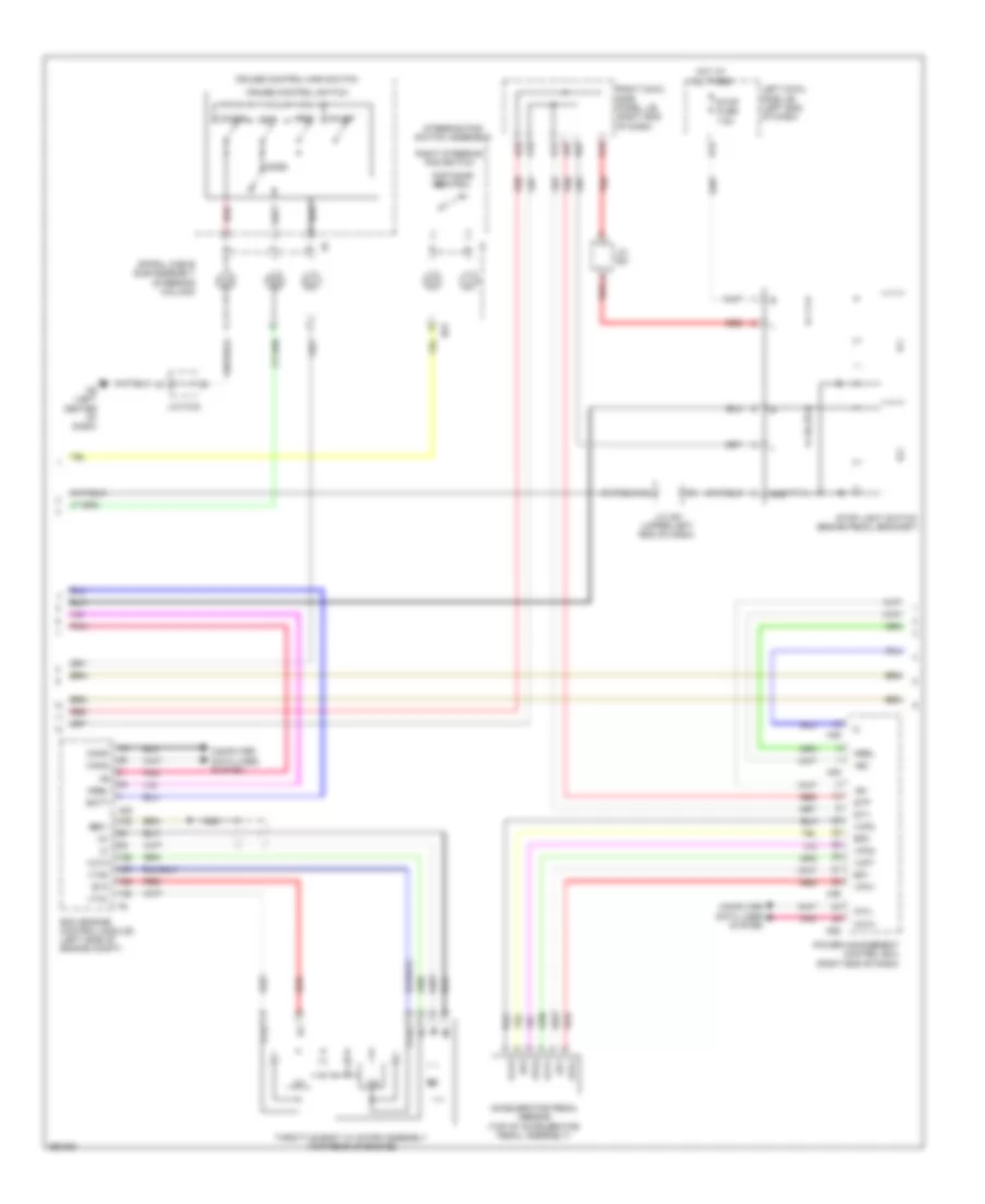
Cruise Control Wiring Diagram, with Dynamic Radar Controls (2 of 3) for Lexus GS 450h 2013
 https://portal-diagnostov.com/license.html
Automotive Electricians Portal FZCO
Automotive Electricians Portal FZCO
https://portal-diagnostov.com/license.html
https://portal-diagnostov.com/license.html
Automotive Electricians Portal FZCO
Automotive Electricians Portal FZCOList of elements for Cruise Control Wiring Diagram, with Dynamic Radar Controls (2 of 3) for Lexus GS 450h 2013:
- +b1
- +b2
- +res
- -set
- A18
- A20
- A22
- A23
- A35
- A36
- Accelerator pedal sensor (top of accelerator pedal assembly)
- Batt
- Ca1h
- Ca1l
- Cancel
- Cann
- Canp
- Computer data lines system
- Cruise control main switch
- Cruise control switch
- D12
- D15
- D22
- Distance control
- Ecm (engine control module) (left side of engine compt)
- Ep1
- Ep2
- Eta
- Ge01
- Gnd
- Hot at all times
- Ic1
- Ic2
- J/c a51
- J/c a51 (upper left end of dash)
- J/c n123
- Left cowl side j/b (left end of dash)
- Mode
- Mrel
- N31
- N6 (left center of dash)
- N92
- Nca
- On-off
- Pnk
- Power management control ecu (right end of dash)
- Red
- Right cowl side panel j/b (right end of dash)
- Right steering pad switch
- Spiral cable sub-assembly (steering column)
- St1-
- Steering pad switch assembly
- Stop fuse 7.5a
- Stop light switch (brake pedal bracket)
- Stp
- Throttle body w/ motor assembly (top rear of engine)
- Vcp1
- Vcp2
- Vcta
- Vpa1
- Vpa2
- Vta
- Vta1
- Vta2
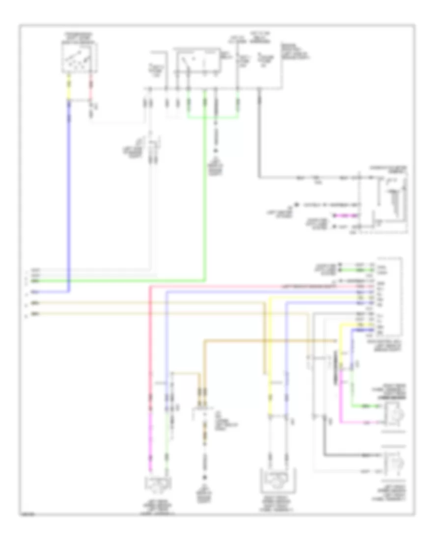
Cruise Control Wiring Diagram, with Dynamic Radar Controls (3 of 3) for Lexus GS 450h 2013
 https://portal-diagnostov.com/license.html
Automotive Electricians Portal FZCO
Automotive Electricians Portal FZCO
https://portal-diagnostov.com/license.html
https://portal-diagnostov.com/license.html
Automotive Electricians Portal FZCO
Automotive Electricians Portal FZCOList of elements for Cruise Control Wiring Diagram, with Dynamic Radar Controls (3 of 3) for Lexus GS 450h 2013:
- (right rear wheel assembly) right rear speed sensor
- (transmission) shift lever position sensor
- 5v ic
- A1 (left rear of engine compt)
- A14
- A16
- At1
- Au1
- Can i/f
- Canh
- Canl
- Combination meter assembly
- Computer data lines system
- Cpu
- Df1
- Engine room r/b 1 (left side of engine compt)
- Fl+
- Fl-
- Fr+
- Fr-
- Gauge fuse 5a
- Gnd
- Hot at all times
- Hot w/ ig2 relay energized
- Igct 1 fuse 30a
- Igct 5 fuse 7.5a
- Igct relay
- J/c a51 (upper left end of dash)
- J/c a71 (left side of engine compt)
- Left front speed sensor (left front wheel assembly)
- Left rear speed sensor (left rear wheel assembly)
- N40
- N6 (left center of dash)
- Na2
- Nca
- Pnk
- Red
- Right front speed sensor (right front wheel assembly)
- Rl+
- Rl-
- Rr+
- Rr-
- Skid control ecu (left rear of engine compt)
- Oa1
- Oa2
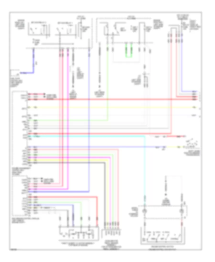
Cruise Control Wiring Diagram, without Dynamic Radar Controls (1 of 2) for Lexus GS 450h 2013
 https://portal-diagnostov.com/license.html
Automotive Electricians Portal FZCO
Automotive Electricians Portal FZCO
https://portal-diagnostov.com/license.html
https://portal-diagnostov.com/license.html
Automotive Electricians Portal FZCO
Automotive Electricians Portal FZCOList of elements for Cruise Control Wiring Diagram, without Dynamic Radar Controls (1 of 2) for Lexus GS 450h 2013:
- +b2
- +res
- -set
- A1 (left rear of engine compt)
- A20
- A22
- A35
- A36
- Accelerator pedal sensor assembly (top of accelerator pedal assembly)
- Af1
- Au1
- Batt
- Can1h
- Can1l
- Cancel
- Cann
- Canp
- Ccs
- Computer data lines system
- Cruise control main switch
- Cruise control switch
- D12
- D15
- D22
- Ecm (engine control module) (left side of engine compt)
- Efi main fuse 25a
- Efi main relay 1
- Efi main relay 2
- Engine room j/b 1 (left side of engine compt)
- Engine room r/b 1 (left side of engine compt)
- Ep1
- Ep2
- Eta
- F/pmp fuse 25a
- F10
- F12
- Fuel pump control ecu (left side of luggage compt)
- Ge01
- Hot at all times
- Hot w/ rh-ig1 rly1 relay energized
- Ic1
- Ic2
- Igct 1 fuse 30a
- Igct 5 fuse 7.5a
- Igct relay
- J/c a53 (left side of engine compt)
- J/c a71 (left side of engine compt)
- Mrel
- N3 (under center console)
- N31
- N92
- Nca
- On- off
- Pnk
- Power management control ecu (right end of dash)
- Red
- Rh ecu-ig fuse 10a
- Right cowl side j/b (right end of dash)
- Sftd
- Sftu
- Shift lever position sensor (transmission)
- Spiral cable (in steering column)
- St1-
- Stp
- Throttle body w/ motor assembly (top rear of engine)
- Vcp1
- Vcp2
- Vcta
- Vpa1
- Vpa2
- Vta1
- Vta2
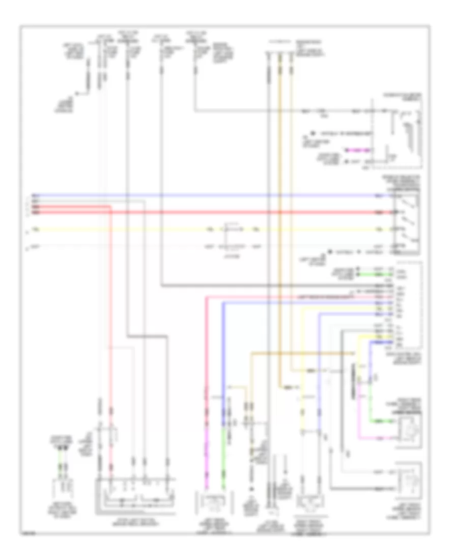
Cruise Control Wiring Diagram, without Dynamic Radar Controls (2 of 2) for Lexus GS 450h 2013
 https://portal-diagnostov.com/license.html
Automotive Electricians Portal FZCO
Automotive Electricians Portal FZCO
https://portal-diagnostov.com/license.html
https://portal-diagnostov.com/license.html
Automotive Electricians Portal FZCO
Automotive Electricians Portal FZCOList of elements for Cruise Control Wiring Diagram, without Dynamic Radar Controls (2 of 2) for Lexus GS 450h 2013:
- (base of selector lever assembly) transmission control switch
- (right rear wheel assembly) right rear speed sensor
- +b11
- 5v ic
- A1 (left rear of engine compt)
- A14
- A16
- Abs main 1 fuse 10a
- At1
- Au1
- Ca1h
- Ca1l
- Can i/f
- Canh
- Canl
- Combination meter assembly
- Computer data lines system
- Cpu
- D12
- D17
- D26
- E10
- E11
- Engine room j/b 1 (left side of engine compt)
- Engine room r/b 1 (left side of engine compt)
- Fl+
- Fl-
- Fr+
- Fr-
- Gauge fuse 5a
- Gnd
- Hot at all times
- Hot w/ ig2 relay energized
- Ic1
- Ic2
- J/c a51 (upper left end of dash)
- J/c a53 (left side of engine compt)
- J/c n126
- Left cowl side j/b (left end of dash)
- Left front speed sensor (left front wheel assembly)
- Left rear speed sensor (left rear wheel assembly)
- Lh-ig2 fuse 10a
- N3 (under center console)
- N40
- N6 (left center of dash)
- Na2
- Nca
- Network gateway ecu (right center of dash)
- Pnk
- Red
- Right front speed sensor (right front wheel assembly)
- Rl+
- Rl-
- Rr+
- Rr-
- Sftd
- Sftu
- Skid control ecu (left rear of engine compt)
- Stop fuse 7.5a
- Stop light switch (brake pedal bracket)
- Oa1
- Oa2

 Čeština
 Dansk
Dansk Deutsch
 Ελληνικά
 English
 English
 Español
 Suomi
Suomi Français
 Français
 עברית
עברית Hrvatski
 Magyar
 Italiano
 日本語
日本語 한국어
한국어 Nederlands
 Polski
 Português
 Português
 Română
 Русский
 Slovenčina
 Slovenščina
 Svenska
 Türkçe
