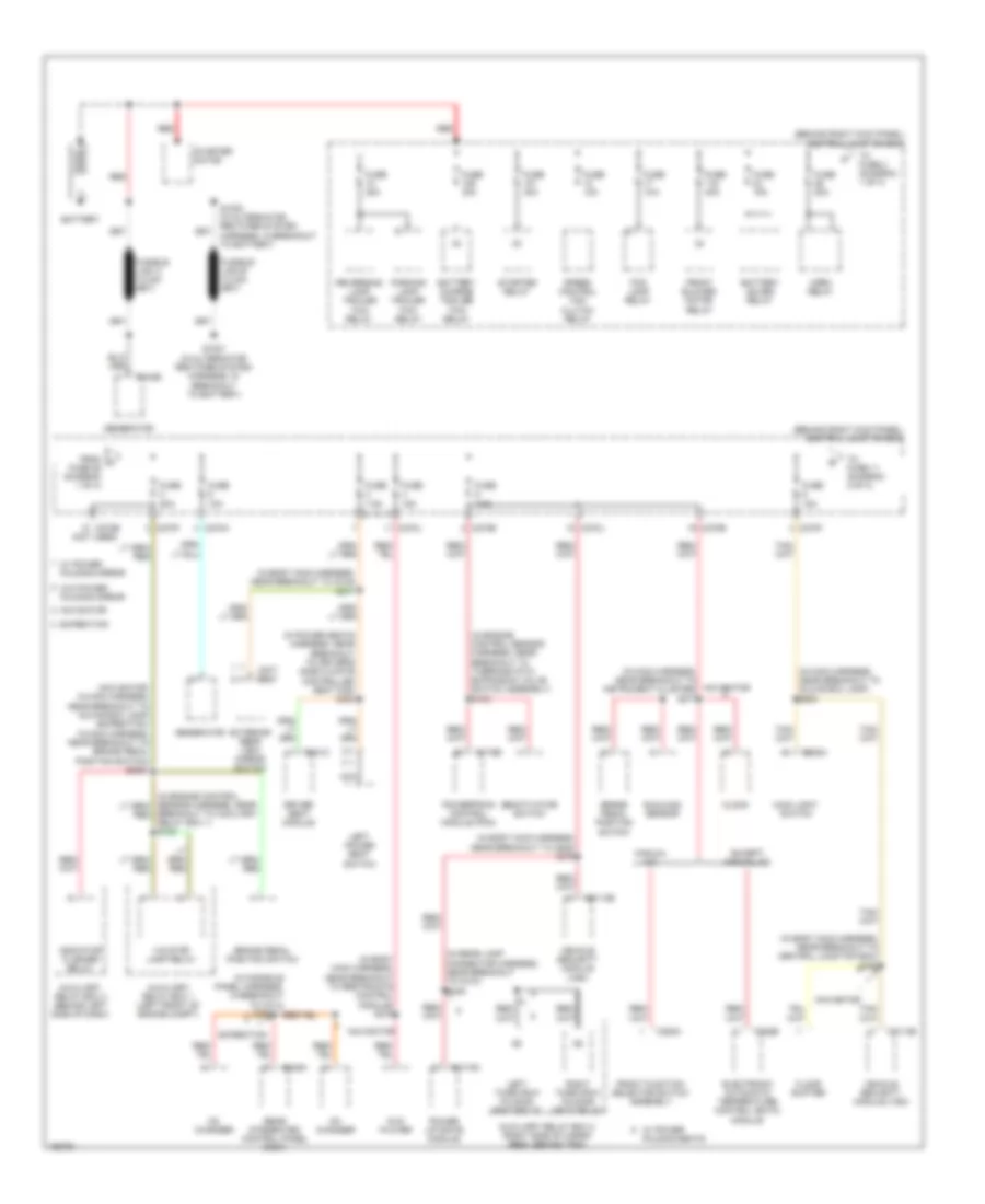
POWER DISTRIBUTION
Power Distribution Wiring Diagram (1 of 4) for Lincoln Navigator 2003
 https://portal-diagnostov.com/license.html
Automotive Electricians Portal FZCO
Automotive Electricians Portal FZCO
https://portal-diagnostov.com/license.html
https://portal-diagnostov.com/license.html
Automotive Electricians Portal FZCO
Automotive Electricians Portal FZCO
List of elements for Power Distribution Wiring Diagram (1 of 4) for Lincoln Navigator 2003:
- (behind right kick panel) central junction box
- (in body main harness, near breakout to c316) s377
- (in body main harness, near breakout to c800) s379
- (in body main harness, near breakout to central junction box) s392
- (in body main harness, near breakout to restraints control module) s372
- (in console panel harness, in breakout to c314)
- (in engine control sensor harness, near breakout to thermostatic expansion valve switch assembly) s133
- (in main harness, near breakout to glove box lamp) s203
- (in main harness, near breakout to instrument cluster) s277
- (in power seats harness, near breakout to driver's side climate controlled seat fan) s384
- (in rear lamp connector harness, near breakout to c410) s448
- (navigator: in main harness, near breakout to glove box lamp) (expedition: in main harness, near breakout to brake pedal position switch) s2001
- (not used)
- Auxiliary relay box 1 (left front of engine compt)
- Auxiliary relay box 2 (right side of cargo area, behind trim)
- Auxiliary relay box 3 (behind left side of dash)
- Battery
- Battery charge trailer tow relay
- Battery saver relay
- Brake pedal position switch
- Breakout to auxiliary relay box 1) s123
- C102b
- C175b
- C205a
- C2113b
- C228b
- C270a
- C270b
- C270e
- C270f
- C270j
- C294c
- C341c
- C349a
- C4174d
- C577 c527
- Cd changer
- Clock
- Deactivator switch
- Driver seat module
- Dvd player
- Electronic automatic temperature control (eatc) module
- Except manual a/c
- Expedition
- Exterior rear view mirror switch
- Floor shifter
- Fog lamp relay
- From a fuse 26 (diagram 1 of 4)
- Front blower motor relay
- Front function selector switch assembly
- Fuse 10a
- Fuse 15a
- Fuse 20a
- Fuse 30a
- Fuse 40a
- Fuse 7.5a
- Generator
- Horn relay
- Indicator flasher relay
- Ivd stop lamp relay
- Left power seat switch
- Left third row folding seat relay
- Main light switch
- Manual a/c
- Navigator
- Nca
- Parking lamp trailer tow relay
- Power liftgate module
- Powertrain control module (pcm)
- Rear integrated control panel (ricp)
- Red
- Reversing lamp trailer tow relay
- Right third row folding seat relay
- S1001 (in alternator rectifier system harness, in breakout to battery)
- S1002 (in alternator rectifier system harness, in breakout to battery)
- S388
- Speed control fan clutch relay
- Starter motor
- Starter relay
- Sunload sensor
- To fuse 11 (diagram 2 of 4)
- To fuse 2 (diagram 1 of 4)
- Vehicle security module (vsm)
- W/ power folding mirror
- W/ power folding seats
- W/o power folding mirror
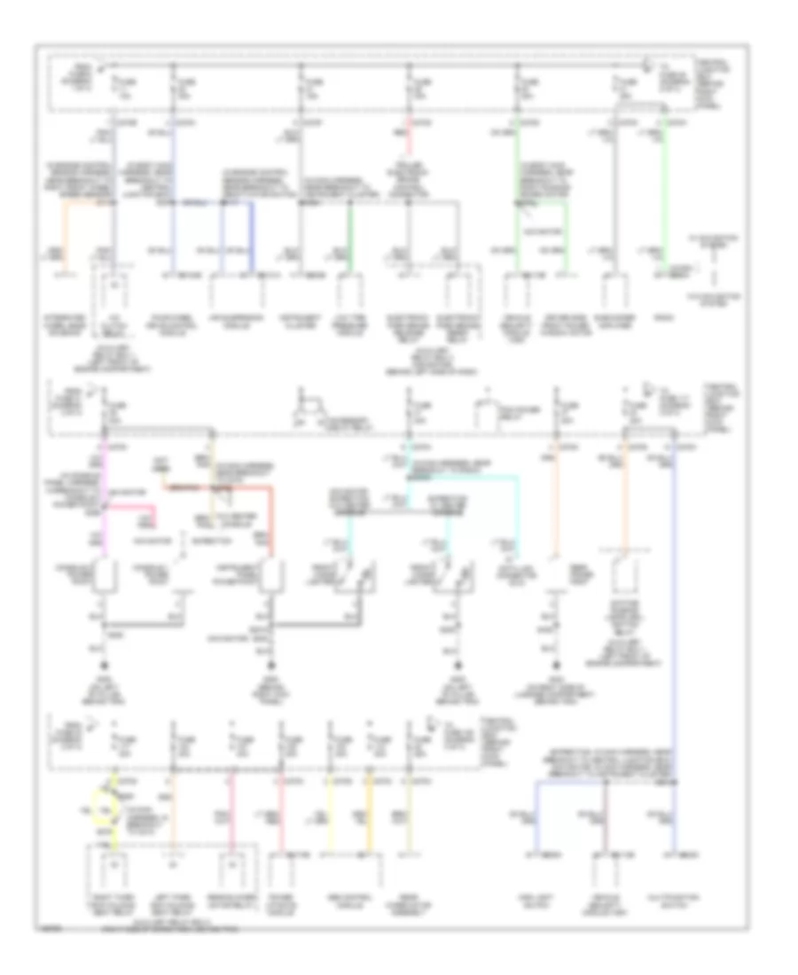
Power Distribution Wiring Diagram (2 of 4) for Lincoln Navigator 2003
 https://portal-diagnostov.com/license.html
Automotive Electricians Portal FZCO
Automotive Electricians Portal FZCO
https://portal-diagnostov.com/license.html
https://portal-diagnostov.com/license.html
Automotive Electricians Portal FZCO
Automotive Electricians Portal FZCOList of elements for Power Distribution Wiring Diagram (2 of 4) for Lincoln Navigator 2003:
- (expedition: in main harness, near breakout to central junction box) (navigator: in main harness, near breakout to instrument cluster) s212
- (in body main harness, near breakout to central junction box) s357
- (in body main harness, near breakout to right running board motor) s391
- (in console panel harness, in breakout to console 2 power point) s396
- (in engine control sensor harness, near breakout to deactivator switch) s117
- (in engine control sensor harness, near breakout to right front wheel speed sensor) s113
- (in main harness, in breakout to c214)
- (in main harness, near breakout to instrument cluster) s238
- (navigator)
- (not used)
- A/c clutch relay
- Abs control module
- Accessory delay relay
- Air suspension module
- Auxiliary relay box 1 (left front of engine compartment)
- Auxiliary relay box 2 (right side of cargo area, behind trim)
- Auxiliary relay box 3 (navigator) (behind left side of dash)
- C202c
- C205a
- C2113b
- C2131a
- C2188a c290a
- C220b
- C270b
- C270c
- C270d
- C270f
- C270g
- C270h
- C270k
- C270m
- C270n
- C3184b
- C4174b
- Central junction box (behind right kick panel)
- Console 1 power point
- Console 2 power point
- Data link connector (dlc)
- Daytime running lamps (drl) ignition relay
- Driver side front power window motor
- Electronic park brake release relay
- Electronic park brake reset relay
- Expedition
- Expedition w/ center console
- Four-wheel drive control module
- From b fuse 6 (diagram 1 of 4)
- From c fuse 31 (diagram 2 of 4)
- From d fuse 40 (diagram 2 of 4)
- Front cigar lighter
- Fuse 10a
- Fuse 15a
- Fuse 20a
- Fuse 25a
- Fuse 30a
- G200 (behind right kick panel)
- G300 (on left ``b" pillar, behind trim)
- G404 (on right side of luggage compartment, behind trim)
- Instrument cluster
- Instrument panel power point
- Integrated wheel ends solenoid
- Left third row folding seat relay
- Low tire pressure module
- Main light switch
- Multifunction switch
- Navigator
- Navigator, expedition w/o center console
- Pcm power relay
- Power liftgate module
- Radio
- Rear blower motor relay
- Rear power point
- Rear wiper motor assembly
- Red
- Right third row folding seat relay
- S2018
- S202
- S205
- S279
- S280
- S436
- Subwoofer amplifier
- To fuse 108 (diagram 3 of 4)
- To fuse 117 (diagram 2 of 4)
- To fuse 39 (diagram 2 of 4)
- Trailer electronic brake control connector
- Vehicle security module (vsm)
- W/ navigation system
- W/o center console
- W/o navigation system
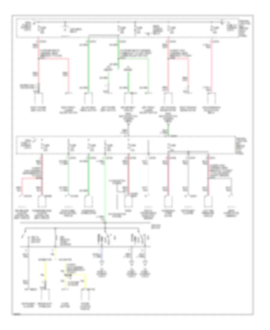
Power Distribution Wiring Diagram (3 of 4) for Lincoln Navigator 2003
 https://portal-diagnostov.com/license.html
Automotive Electricians Portal FZCO
Automotive Electricians Portal FZCO
https://portal-diagnostov.com/license.html
https://portal-diagnostov.com/license.html
Automotive Electricians Portal FZCO
Automotive Electricians Portal FZCOList of elements for Power Distribution Wiring Diagram (3 of 4) for Lincoln Navigator 2003:
- (expedition) a
- (in body main harness, near breakout to c316) s375
- (in body main harness, near breakout to g301) s395
- (in body main harness, near breakout to right ``c" pillar safety canopy sensor) s315
- (in power seats harness, in breakout to left front lumbar adjust switch) s310
- (in power seats harness, near breakout to c316) s311
- (navigator)
- Acc
- Adjustable pedal switch
- Air suspension solid state relay
- Brake shift interlock
- C2188c c290a
- C220a
- C270b
- C270c
- C270d
- C270e
- C270f
- C270g
- C270h
- C270j
- C270m
- C3031b
- C3036b
- C3184b
- C341a
- C4174d
- Central junction box (behind right kick panel)
- Digital transmission rane (dtr) sensor
- Driver seat module
- Driver side climate controlled seat module
- Expedition
- Floor shifter
- Four-wheel drive control module
- From e fuse 38 (diagram 2 of 4)
- From f fuse 111 (diagram 3 of 4)
- From ignition switch (diagram 3 of 4)
- Fuse 10a
- Fuse 30a
- Fuse 40a
- Fuse 50a
- Fuse 7.5a
- High beam relay
- Ignition switch
- Instrument cluster
- Key in ignition switch
- Key removal inhibit solenoid
- Left front lumbar adjust switch
- Left power seat switch
- Left running board motor
- Lock
- Low tire pressure module
- Navigator
- Nca
- Off
- Passenger side climate controlled seat module
- Power liftgate module
- Radio
- Rear window defrost relay
- Rear wiper motor assembly
- Right front lumbar adjust switch
- Right power seat switch
- Right running board motor
- Run
- Start
- To fuse 1 (diagram 3 of 4)
- To fuse 118 (diagram 3 of 4)
- To fuse 13 (diagram 4 of 4)
- To fuse 7 (diagram 3 of 4)
- W/ memory
- W/ navigation system
- W/ power liftgate
- W/o memory
- W/o navigation system
- Windshield wiper motor
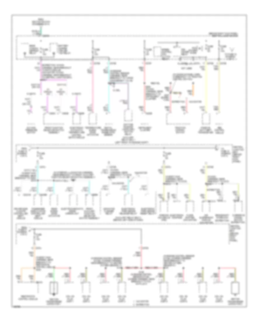
Power Distribution Wiring Diagram (4 of 4) for Lincoln Navigator 2003
 https://portal-diagnostov.com/license.html
Automotive Electricians Portal FZCO
Automotive Electricians Portal FZCO
https://portal-diagnostov.com/license.html
https://portal-diagnostov.com/license.html
Automotive Electricians Portal FZCO
Automotive Electricians Portal FZCOList of elements for Power Distribution Wiring Diagram (4 of 4) for Lincoln Navigator 2003:
- (behind right kick panel) central junction box
- (expedition)
- (in body main harness, near breakout to c316) s318
- (in body main harness, near breakout to c800) s319
- (in body main harness, near breakout to restraints control module) s320
- (in console panel harn, in breakout to traction control switch)
- (in engine control sensor & fuel charge harness, near breakout to heated oxygen sensor 11) s132
- (in engine control sensor & fuel charge harness, near breakout to heated oxygen sensor 21) s124
- (in interior illumination harness, near breakout to front auxiliary function selector switch assembly) s903
- (in main harness, near breakout to c210) s221
- (left front of engine compt)
- (navigator)
- A/c high pressure switch
- Abs control module
- Air suspension module
- Auxiliary relay box 1
- Auxiliary relay box 3 (behind left side of dash)
- Battery charge trailer tow relay
- Brake shift interlock
- C2131a
- C220b
- C228b
- C270b
- C270d
- C270e
- C270f
- C270g
- C270j
- C294b
- C294c
- C3031b
- C3036b
- C310a
- C4014b
- C989b
- Central junction box (behind right kick panel)
- Coil on plug (cop) 1
- Coil on plug (cop) 2
- Coil on plug (cop) 3
- Coil on plug (cop) 4
- Coil on plug (cop) 5
- Coil on plug (cop) 6
- Coil on plug (cop) 7
- Coil on plug (cop) 8
- Daytime running lamps (drl) ignition relay
- Digital transmission range (dtr) sensor
- Driver side climate controlled seat module
- Electrochromatic inside mirror unit
- Electronic automatic temperature control (eatc) module
- Electronic compass
- Electronic park brake release relay
- Electronic park brake reset relay
- Expedition
- Floor shifter (navigator)
- From fuse 27 k (diagram 4 of 4)
- From ignition switch (diagram 3 of 4)
- From j fuse 16 (diagram 4 of 4)
- Front auxiliary function selector switch assembly
- Front function selector switch assembly
- Fuse 10a
- Fuse 5a
- Harness, near breakout to c219) s228
- Ignition transformer capacitor 1
- Ignition transformer capacitor 2
- Indicator flasher relay
- Instrument cluster
- Navigator
- Nca
- Not used
- Overdrive cancel switch (expedition)
- Parking aid module (pam)
- Passenger side climate controlled seat module
- Passive anti-theft transceiver
- Pcm power diode
- Pcm power relay
- Rear blend door actuator
- Rear window defrost relay
- Restraints control module
- S129 (in engine control sensor & fuel charge harness, near breakout to coil on plug 4)
- S282 (in main harness, near breakout to instrument cluster)
- S387 (exped- ition)
- Speed control fan clutch relay
- Tan/ red
- Temperature blend door actuator
- To eatc module) (navigator: in main harness, near breakout to central junction box) s241
- To fuse 18 (diagram 4 of 4)
- To fuse 19 (diagram 4 of 4)
- Traction control switch
- W/ drl
- W/ eatc
- W/ manual a/c

 Čeština
 Dansk
Dansk Deutsch
 Ελληνικά
 English
 English
 Español
 Suomi
Suomi Français
 Français
 עברית
עברית Hrvatski
 Magyar
 Italiano
 日本語
日本語 한국어
한국어 Nederlands
 Polski
 Português
 Português
 Română
 Русский
 Slovenčina
 Slovenščina
 Svenska
 Türkçe
