SHIFT INTERLOCKS
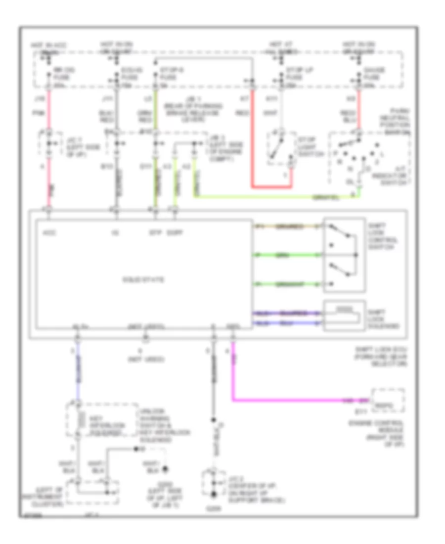
Shift Interlock Wiring Diagram for Lexus LS 400 1997
List of elements for Shift Interlock Wiring Diagram for Lexus LS 400 1997:
- (left of instrument cluster)
- (not used)
- 10a
- 15a
- 25a
- A/t indicator switch
- Acc
- B13
- B17
- D11
- Doff
- E11
- Ecu-ig fuse
- Engine control module (right side of i/p)
- G202 (left side of i/p, left of j/b 1)
- G206
- Gauge fuse
- Hot at all times
- Hot in acc or on
- Hot in on or start
- J/b 1 (rear of parking brake release lever)
- J/b 3 (left side of engine compt)
- J/c 1
- J/c 2 (center of i/p, on right i/p support brace)
- J/c 7 (left side of i/p)
- J11
- J16
- K11
- Key interlock solenoid
- Kls+
- Park/ neutral position switch
- Pnk
- Red
- Rr cig fuse
- Rspd
- Shift lock control switch
- Shift lock ecu (forward gear selector)
- Shift lock solenoid
- Sls+
- Sls-
- Solid state
- Spd
- Stop light switch
- Stop lp fuse
- Stop-s fuse
- Stp
- Unlock warning switch & key interlock solenoid
 Čeština
 Dansk
Dansk Deutsch
 Ελληνικά
 English
 English
 Español
 Suomi
Suomi Français
 Français
 עברית
עברית Hrvatski
 Magyar
 Italiano
 日本語
日本語 한국어
한국어 Nederlands
 Polski
 Português
 Português
 Română
 Русский
 Slovenčina
 Slovenščina
 Svenska
 Türkçe
 中文 (中国)