ANTI-LOCK BRAKES
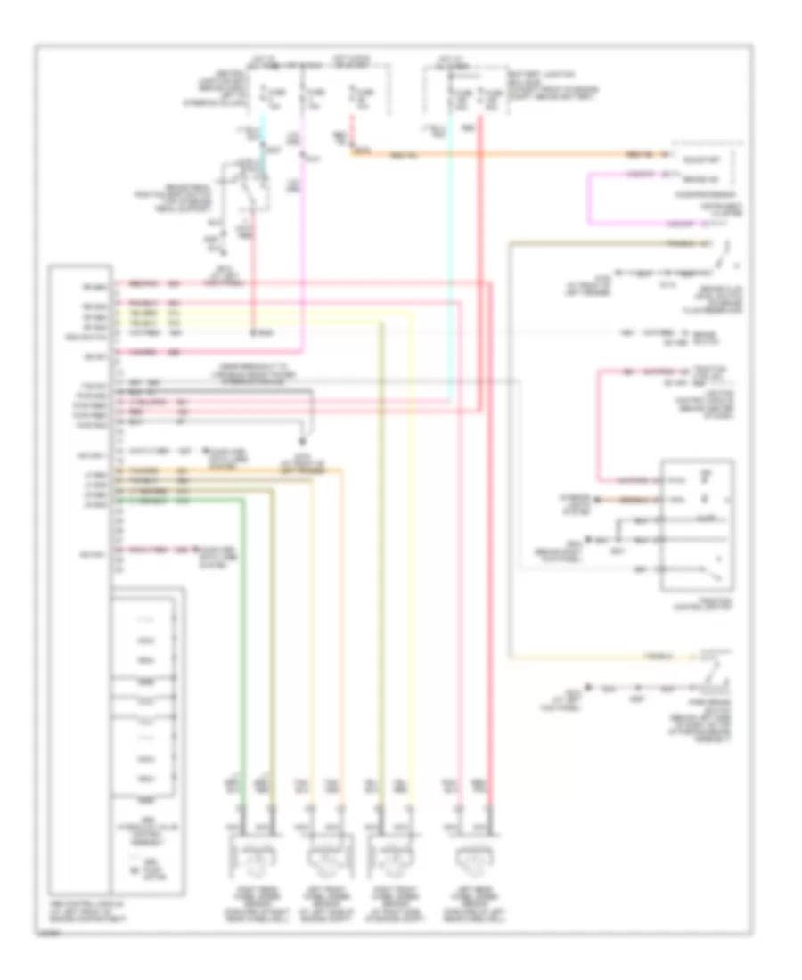
Anti-lock Brakes Wiring Diagram for Ford Crown Victoria LX 2006
 https://portal-diagnostov.com/license.html
Automotive Electricians Portal FZCO
Automotive Electricians Portal FZCO
https://portal-diagnostov.com/license.html
https://portal-diagnostov.com/license.html
Automotive Electricians Portal FZCO
Automotive Electricians Portal FZCO
List of elements for Anti-lock Brakes Wiring Diagram for Ford Crown Victoria LX 2006:
- (near breakout to variable assist power steering module)
- Abs control module (at left front of engine compartment)
- Abs hydraulic valve control assembly
- Abs pump motor
- Battery junction box (bjb) (in right front of engine compt, behind battery)
- Boo switch
- Brake fluid level switch (on brake fluid reservoir)
- Brake ind
- Brake pedal position (bpp) switch (top of brake pedal support)
- Brake switch c2145b
- C2145a
- Central junction box (behind dash, left of steering column)
- Computer data lines system
- Ctrl sw ind
- Fuse 10a
- Fuse 20a
- Fuse 40a
- G102 (at front of left fender)
- G103 (at front of left fender)
- G204 (behind right kick panel)
- G212 (at left kick panel)
- Hot at all times
- Hot in run
- Hot in run or start
- Hs can +
- Hs can -
- Ign sw
- Illum
- Ind
- Instrument cluster
- Interior lights system
- Left front wheel speed sensor (at left side of engine compt)
- Left rear wheel speed sensor (forward of left rear wheelwell)
- Lf gnd
- Lf sen
- Lighting control module (behind center of dash)
- Lr gnd
- Lr sen
- Microprocessor
- Nca
- Park brake switch (behind left side of dash, on top of parking brake assembly)
- Pwr feed
- Pwr gnd
- Red
- Red/ pnk
- Red/pnk
- Rf gnd
- Rf sen
- Right front wheel speed sensor (at right side of engine compt)
- Right rear wheel speed sensor (forward of right rear wheelwell)
- Rr gnd
- Rr sen
- Run/start
- S101
- S112
- S201
- S225
- S237
- S267
- S276
- Tcs sw
- Traction
- Traction control switch
 Čeština
 Dansk
Dansk Deutsch
 Ελληνικά
 English
 English
 Español
 Suomi
Suomi Français
 Français
 עברית
עברית Hrvatski
 Magyar
 Italiano
 日本語
日本語 한국어
한국어 Nederlands
 Polski
 Português
 Português
 Română
 Русский
 Slovenčina
 Slovenščina
 Svenska
 Türkçe
 中文 (中国)
