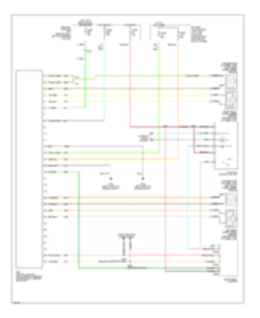
ANTI-LOCK BRAKES
Anti-lock Brake Wiring Diagrams for Ford Mustang GT Bullitt 2002
 https://portal-diagnostov.com/license.html
Automotive Electricians Portal FZCO
Automotive Electricians Portal FZCO
https://portal-diagnostov.com/license.html
https://portal-diagnostov.com/license.html
Automotive Electricians Portal FZCO
Automotive Electricians Portal FZCO
List of elements for Anti-lock Brake Wiring Diagrams for Ford Mustang GT Bullitt 2002:
- (inboard side of wheel hub) left front wheel speed sensor
- (inboard side of wheel hub) right rear wheel speed sensor
- 3.8l
- 4.6l
- Abs control module (right front of engine compartment, behind radiator)
- Battery junction box (left side of engine compartment, forward of strut tower)
- C220a
- C220b
- Central junction box (behind dash, left of steering column)
- Computer data lines system
- Fuse 15a
- Fuse 20a
- Fuse 50a
- G102 (left front of engine compt)
- G103 (right front of engine compt)
- Hot at all times
- Hot in run
- Hot with brake pedal depressed
- Instrument cluster
- Interior lights system
- Left rear wheel speed sensor (inboard side of wheel hub)
- Nca
- Right front wheel speed sensor (inboard side of wheel hub)
- S252 (behind center of dash)
- S253 (center of dash)
- S257
- S275
- S284
- Traction control switch
 Čeština
 Dansk
Dansk Deutsch
 Ελληνικά
 English
 English
 Español
 Suomi
Suomi Français
 Français
 עברית
עברית Hrvatski
 Magyar
 Italiano
 日本語
日本語 한국어
한국어 Nederlands
 Polski
 Português
 Português
 Română
 Русский
 Slovenčina
 Slovenščina
 Svenska
 Türkçe
 中文 (中国)
